WO2007079990A1 - Method and device for fault location in a two-terminal transmission or distribution power line - Google Patents

Method and device for fault location in a two-terminal transmission or distribution power line Download PDF

Info

Publication number
WO2007079990A1
WO2007079990A1 PCT/EP2006/066229 EP2006066229W WO2007079990A1 WO 2007079990 A1 WO2007079990 A1 WO 2007079990A1 EP 2006066229 W EP2006066229 W EP 2006066229W WO 2007079990 A1 WO2007079990 A1 WO 2007079990A1
Authority
WO
WIPO (PCT)
Prior art keywords
fault
current
line
distance
terminals
Prior art date
Legal status (The legal status is an assumption and is not a legal conclusion. Google has not performed a legal analysis and makes no representation as to the accuracy of the status listed.)
Ceased
Application number
PCT/EP2006/066229
Other languages
French (fr)
Inventor
Murari Saha
Eugeniusz Rosolowski
Jan Izykowski
Current Assignee (The listed assignees may be inaccurate. Google has not performed a legal analysis and makes no representation or warranty as to the accuracy of the list.)
ABB Technology AG
Original Assignee
ABB Technology AG
Priority date (The priority date is an assumption and is not a legal conclusion. Google has not performed a legal analysis and makes no representation as to the accuracy of the date listed.)
Filing date
Publication date
Application filed by ABB Technology AG filed Critical ABB Technology AG
Priority to US12/160,552 priority Critical patent/US8183871B2/en
Priority to CN2006800508915A priority patent/CN101356444B/en
Priority to EP06793410.9A priority patent/EP1971869B1/en
Priority to HK09104390.9A priority patent/HK1128766B/en
Publication of WO2007079990A1 publication Critical patent/WO2007079990A1/en
Anticipated expiration legal-status Critical
Ceased legal-status Critical Current

Links

Classifications

    • GPHYSICS
    • G01MEASURING; TESTING
    • G01RMEASURING ELECTRIC VARIABLES; MEASURING MAGNETIC VARIABLES
    • G01R31/00Arrangements for testing electric properties; Arrangements for locating electric faults; Arrangements for electrical testing characterised by what is being tested not provided for elsewhere
    • G01R31/50Testing of electric apparatus, lines, cables or components for short-circuits, continuity, leakage current or incorrect line connections
    • GPHYSICS
    • G01MEASURING; TESTING
    • G01RMEASURING ELECTRIC VARIABLES; MEASURING MAGNETIC VARIABLES
    • G01R31/00Arrangements for testing electric properties; Arrangements for locating electric faults; Arrangements for electrical testing characterised by what is being tested not provided for elsewhere
    • G01R31/08Locating faults in cables, transmission lines, or networks
    • G01R31/088Aspects of digital computing
    • GPHYSICS
    • G01MEASURING; TESTING
    • G01RMEASURING ELECTRIC VARIABLES; MEASURING MAGNETIC VARIABLES
    • G01R31/00Arrangements for testing electric properties; Arrangements for locating electric faults; Arrangements for electrical testing characterised by what is being tested not provided for elsewhere
    • G01R31/08Locating faults in cables, transmission lines, or networks
    • G01R31/081Locating faults in cables, transmission lines, or networks according to type of conductors
    • G01R31/085Locating faults in cables, transmission lines, or networks according to type of conductors in power transmission or distribution lines, e.g. overhead

Definitions

  • This invention relates to a method and a device for locating a fault within a two-terminal power transmission or distribution line.
  • Power transmission lines carry electric power from generating sources to users.
  • the power transmission lines are typically high voltage lines and the electric voltage is typically transformed to a lower voltage at a power substation, before being distributed to individual electric power users such as homes, factories, business buildings etc.
  • protective relays are installed at many power substations.
  • a fault in the line involves measuring critical system parameters and, when a fault occurs, quickly making a rough estimate of the fault location and of certain characteristics of the fault so that the faulted line can be isolated from the power grid as quickly as possible.
  • a fault occurs when a transmission line, typically due to external causes, diverts electrical current flow from its normal path along the transmission line.
  • the major types and causes of faults are insulation faults, caused by design defects, manufacturing defects, improper installation, and aging insulation; electrical faults, caused by lightning surges, switching surges, and dynamic overvolt- ages; mechanical faults, caused by wind, snow, ice, contamination, trees, and animals; and thermal faults, caused by overcurrent and overvoltage conditions.
  • a transmission line may include three phase lines; however, a transmission line may also contain one phase, or some other number of phases.
  • complete measurements describes the fact that currents and voltages of both ends and of all phases of the transmission or distribution line are measured and are being available as a complete set of measurements .
  • the measurements are considered as acquired asynchronously .
  • the synchronization angle Prior to calculating the distance to fault the synchronization angle is determined in order to assure the common time reference for measurements from both line ends.
  • the object of the present invention is to create an improved, simple and reliable method and device for locating faults in a two-terminal power transmission or distribution line using synchronized measurements of the phase currents of the two terminals .
  • the object is achieved by a method according to claim 1 and a device according to claim 6.
  • the fault location method according to the invention can be categorized as an impedance-based method. It uses as input signals the three phase currents from both line terminals and the three phase voltages only from one of the line terminals. Additional input signals are transmission parameters of the line and the fault type. Based on these input signals the distance to fault is determined and output to an output interface .
  • the device for locating a fault also called a fault locator
  • a processing unit which processes according to the invention the three phase currents from both ends of the line, the three phase voltages from one of the line terminals, the transmission parameters of the line and the fault type to determine the distance to fault.
  • the processing unit outputs the distance to fault to an output interface, from where the distance to fault can be transmitted to a display, a data memory unit or an external data network.
  • the provided current signals from both ends of the line are considered as being synchronized. In case this is not so, the synchronization angle can be determined using the known algorithms.
  • the main advantage of the invention is that since the phase voltages of only one end of the line are needed to determine the fault location, a device which is attached to one end of the line and which is, during normal working mode, provided with the currents from its own end, also called the local end or the local terminal, and with the currents from the other end of the line, that this device can now be enabled to determine the fault location even if a fault has occurred which allows no further data communication from the other end of the line.
  • the method according to the invention requires only the possibility to receive the phase voltages from the local end.
  • the invention allows expanding the functionality of a current differential relay which is commonly placed at one end of a line for protection purposes. During normal working mode the current differential relay is provided with the phase currents from its local line terminal as well as from the other of the two line terminals. The current differential relay can now be supplemented with the off-line capability for precise location of a fault.
  • the fault location method according to the invention is categorized as an impedance-based method and it is formulated as an algorithm with using the phasors of symmetrical components of the measured quantities.
  • the parameters of the line as well as the phasors of the currents and voltages processed by the processing unit are considered as determined for the rated angular frequency: CO 1 , given in units of 1/s.
  • the symmetrical components of all the processed signals are determined for the sequence of phases: a, b, c.
  • the first or basic version of the fault location algorithm applies the so called lumped model of the power line without taking into account the shunt parameters.
  • a very simple first order equation for the distance to fault has been obtained.
  • the optimal determination of the total fault current i.e. the current flowing through a fault resistance, from the available measurements of two-end currents has been applied.
  • the positive, negative and zero sequence current components are multiplied by special coefficients, where the values of the coefficients depend on the current fault type. These coefficients are called share coefficients in the following .
  • the second or extended version of the fault location algorithm has been derived with the intention of improving the fault location accuracy in case of long lines, say of the length exceeding 150 km.
  • the so called distributed parameter model of the line has been applied. Strict application of this model was applied when determining the voltage drop across the faulted line section and also for determining the voltage drop across the fault path resistance. Since the determined voltage drop across the fault resistance involves in this case the impedance or admittance parameters of the line, the values of the share coefficients differ from those used in the first version of the algorithm. Namely, the zero sequence components were eliminated in order to avoid adverse influence of uncertainty with respect to zero sequence data of the line.
  • the second form of the fault location algorithm is of the form of a non-linear formula. Different to solving it with the use of well-known numerical methods, simple iterative calculations based on using simplified models of the faulted line, however, accounting for the distributed nature of the power line, have been proposed.
  • Figure 1 illustrates a two-terminal transmission line comprising differential relays and a fault locator.
  • Figure 2 illustrates an equivalent circuit diagram of the transmission line for the positive sequence.
  • Figure 3 illustrates an equivalent circuit diagram of the transmission line for the negative sequence.
  • Figure 4 illustrates an equivalent circuit diagram of the transmission line for the zero sequence.
  • Figure 5 illustrates a distributed parameter model of the transmission line for the positive sequence.
  • Figure 6 illustrates a distributed parameter model of the transmission line for the negative sequence.
  • Figure 7 illustrates a distributed parameter model of the transmission line for the zero sequence.
  • Figure 8 illustrates a simplified distributed parameter model of the transmission line for the positive sequence.
  • Figure 9 illustrates a simplified distributed parameter model of the transmission line for the negative sequence.
  • Figure 10 illustrates a simplified distributed parameter model of the transmission line for the zero sequence.
  • Figure 11 illustrates a flow chart of the steps of a method for locating a fault on the transmission line.
  • Figure 1 illustrates the arrangement of a two-terminal line, which is considered as protected by current differential protective relays DIFF REL A and DIFF REL B , which are installed at both line ends. The other types of protection for the line are not discussed here.
  • the terminals of the line are denoted by A and B.
  • the fault point is marked by F.
  • a fault locator FL is incorporated into the differential relay DIFF REL A of the substation A.
  • This relay DIFF REL A is supplied with the local three-phase instantaneous currents, which after being digitalized are converted into the three phase current phasors _I A _ a , I_ R _b and I_ R _ C .
  • the relay DIFF REL A receives, via the communication channel, the three phase current phasors I ⁇ _a, Is l and I_ B _ C of the remote or other end of the line, substation B.
  • the phasors are considered here as measured synchronously, which is required for performing the current differential protection of the line.
  • the fault locator FL is supplied with the local three-phase voltages, which after being digitalized are converted into the three voltage phase phasors V R _ ar V R _ h and
  • V A _ C The voltage phasors V R _ ar V R _ h and V A _ C are also considered as measured synchronously with the local current phasors _I A _ a , I A _b and I A _c.
  • the fault locator and the fault location algorithm apply the following measurements of phasors:
  • /_ A stands for the three phase currents from the side A from particular phases a, b, c:
  • V A stands for the three phase voltages from the side A from particular phases a, b, c: La- KA b' KA c and
  • /g stands for the three phase currents from the side B from particular phases a, b, c: •
  • the fault location algorithm requires the following parameters: transmission parameters of the line in form of impedance or admittance data of the line and the fault type, where the fault type can be provided from a protection unit or a dedicated classification procedure can be incorporated into the fault location method.
  • the generalized fault loop model is utilized for deriving the fault location procedure. This is a single formula with the coefficients dependent on a fault type, thus covering different fault types:
  • ⁇ 1 5 ⁇ _ 2 ' ⁇ o are weighting coefficients dependent on the fault type, outlined in Table 1,
  • equation (1) there are two unknowns: the distance to fault d and the fault resistance R F .
  • Lm ' L F2 I L FO are symmetrical components of the total fault current, where the subscript 1 denotes the positive, subscript 2 denotes the negative and subscript 0 denotes the zero sequence, respectively) , and a F1 , ap j , a F0 are share coefficients, dependent on the fault type.
  • the particular sequence components / F1 , J_ ⁇ 2 and / F0 of the total fault current I F are determined by the sum of the respective sequence components of currents from the line terminals A and B.
  • the first subscript, A or B denotes the terminal, while the second subscript 1, 2 or 0 denotes again the respective sequence component:
  • the positive sequence component / F1 of the total fault current I F can be determined with the use of the superimposed incremental positive sequence currents ⁇ J Ai and
  • the fault location accuracy is deteriorated, especially significantly if a high fault resistance is involved.
  • the use of the negative and zero sequence components and of the superimposed positive sequence components is advantageous for assuring high accuracy of the fault location.
  • Y 1 Y, is the propagation constant of the line for the negative sequence
  • Z c i is the characteristic impedance of the line for the positive sequence
  • Z L2L Z_ VL i s the impedance of the line for the negative sequence given in units of /km
  • F 1L G 1L +j& ⁇ C 1L is the admittance of the line for the positive sequence given in units of S/km
  • F 0L G 0L +j ⁇ C 0L is the admittance of the line for the zero sequence given in units of S/km,
  • Figures 5-7 illustrate the distributed parameter models of the faulted transmission line for the respective sequences.
  • equations (6) or (9) The distance to fault d according to equations (6) or (9) is determined under neglecting the shunt capacitances of the transmission line. In case of short lines, say up to 150 km, equations (6) and (9) are sufficient for achieving high accuracy of fault location. However, for longer lines the distributed parameter nature of the line has to be taken into account and the effect of the shunt capacitances has to be compensated for. The derivation of an according algorithm follows .
  • the generalized fault loop model is applied for determining the distance to fault.
  • the generalized model describing the fault loop seen from the terminal A is formulated as follows:
  • Vp (d) is the fault loop voltage, composed according to the fault type, after analytic transfer from the terminal A to the fault point F, / F is the fault path current or total fault current.
  • Y Fp (d) a 1 V F1 + a 2 V_ F2 + a 0 V_ F0 ( 1 6 )
  • a lr a 2 , a 0 are weighting coefficients dependent on the fault type, as outlined in Table 1.
  • Y- A i ' Y A2> Y AO are the symmetrical components of side A voltages, with the subscript 1 denoting the positive sequence component, subscript 2 the negative sequence component and subscript 0 the zero sequence component, and L AI r L A2> L AO are the symmetrical components of side A currents .
  • hyperbolic functions can be expressed as:
  • equations (23) -(24) can be linearized by taking into account that:
  • the linearized equation (A9) can be utilized for starting iterative calculations of the distance to fault d.
  • M 2 / A2 cosh( ⁇ 2 ⁇ ) + / B2 ⁇ -E A2 sinh(7 2 ⁇ ) ( 26 ;
  • Utilizing the generalized fault model in the form of the equation (15) requires selecting the share coefficients a F1 , a K and a F0 .
  • the obtained generalized fault loop model (31) can be solved by using numerical methods for solving a set of non-linear equations.
  • the Newton-Raphson method can be applied for that.
  • n denotes the previous iteration step
  • n+1 denotes the current iteration step
  • J (J1+1) is the value of the distance to fault obtained as the result of performing the current iteration step
  • d (a) is the value of the distance to fault obtained in the previous iteration step, which when starting the iterative calculations is obtained from the fault location algorithm for the lumped model of the transmission line according to equation (6) or (9) .
  • the fault loop voltage V Rp from equation (32) is composed of symmetrical components V_ A1 , V R2 and V R3 , with using the weighting coefficients outlined in Table 1:
  • the quantity is determined with a simplification, namely with taking into account the impedance and admittance parameters of the faulted line section between terminal A and fault F, considered as being of the length equal to the value of the previous value of the distance to fault d ⁇ n) :
  • the symmetrical components of the currents are used for calculation of the fault loop quantity according to equation (34) .
  • the currents are obtained by deducing the respective shunt currents:
  • the total fault current after taking into account that the zero sequence component is excluded can be expressed as follows :
  • the method to determine the distance to fault outlined above is especially suitable to be incorporated as an added feature into a current differential relay.
  • the current differential relay When the current differential relay is applied to protect a two-terminal line, it utilizes the phase currents measured synchronously at both line terminals for the protection purposes. Therefore, in order to incorporate the fault location function additionally to the protection function itself, the local phase voltages, i.e. the phase voltages from the terminal where the differential relay is installed, which is presumed to be the terminal A in the further considerations, have to be supplied to the relay.
  • the differential relay equipped with the fault location feature can identify the fault not only in terms whether it occurred within the zone or outside it, which is already part of the known differential relay principle, but also more precisely in terms of determining the exact distance from the local line terminal.
  • This additional feature of the current differential relay can for example be used to support and simplify inspection and repair of a faulty transmission or distribution line.

Landscapes

  • Physics & Mathematics (AREA)
  • General Physics & Mathematics (AREA)
  • Engineering & Computer Science (AREA)
  • Mathematical Physics (AREA)
  • Theoretical Computer Science (AREA)
  • Locating Faults (AREA)
  • Emergency Protection Circuit Devices (AREA)

Abstract

A method for locating a fault in a two-terminal power transmission or distribution line comprises the steps of receiving measurements of the three phase currents from both terminals, receiving measurements of the three phase voltages from one line terminal, receiving parameters of the line and receiving the fault type. Based on this information the distance to fault from the one terminal where the phase voltages were measured is determined and output. Since only the phase voltages of one line terminal are needed, the functionality of a device, in particular a current 15 differential relay, can be expanded to determine the distance to fault in an off-line mode.

Description

METHOD AND DEVICE FOR FAULT LOCATION IN A TWO-TERMINAL TRANSMISSION OR DISTRIBUTION POWER LINE
TECHNICAL FIELD
This invention relates to a method and a device for locating a fault within a two-terminal power transmission or distribution line.
BACKGROUND OF THE INVENTION
Power transmission lines carry electric power from generating sources to users. The power transmission lines are typically high voltage lines and the electric voltage is typically transformed to a lower voltage at a power substation, before being distributed to individual electric power users such as homes, factories, business buildings etc. At many power substations, protective relays are installed.
The detection of a fault in the line involves measuring critical system parameters and, when a fault occurs, quickly making a rough estimate of the fault location and of certain characteristics of the fault so that the faulted line can be isolated from the power grid as quickly as possible. A fault occurs when a transmission line, typically due to external causes, diverts electrical current flow from its normal path along the transmission line.
The major types and causes of faults are insulation faults, caused by design defects, manufacturing defects, improper installation, and aging insulation; electrical faults, caused by lightning surges, switching surges, and dynamic overvolt- ages; mechanical faults, caused by wind, snow, ice, contamination, trees, and animals; and thermal faults, caused by overcurrent and overvoltage conditions.
A transmission line may include three phase lines; however, a transmission line may also contain one phase, or some other number of phases.
PRIOR ART
The issue of locating faults in two-terminal power transmission or distribution lines has been disclosed in different prior art, where two-terminal line means that on each of the two ends of the line a terminal is placed.
In M. Kezunovic and B. Perunicic, ("Automated transmission line fault analysis using synchronized sampling at two ends", IEEE Trans, on Power Systems, pp. 441-447, PS-Il, 1996) the use of complete measurements of three-phase currents and voltages from both terminals of the line has been considered for fault location. These measurements were assumed as being synchronized, i.e. to have a common time reference.
In the following, the phrase "complete measurements" describes the fact that currents and voltages of both ends and of all phases of the transmission or distribution line are measured and are being available as a complete set of measurements .
Similarly, the availability of complete two-terminal measurements has been considered in NOVOSEL D. ("Automatic fault location system", United States Patent, No. 5,455,776; 3.10.1995.), in D. Novosel, D. G. Hart, E. Udren and J. Garitty J, ("Unsynchronized two-terminal fault location estimation", IEEE Trans, on Power Delivery, vol. 11, pp. 130- 138, No. 1, 1996), and in Girgis A.A. , Hart D. G., Peterson
W. L., ("A new fault location technique for two-and three- terminal lines", IEEE Trans. Power Delivery, Vol. 7, No.l, pp. 98-107, January 1992.).
However, the measurements are considered as acquired asynchronously . Prior to calculating the distance to fault the synchronization angle is determined in order to assure the common time reference for measurements from both line ends.
In Tziouvaras D.A., Roberts J., Benmmouyal G., ("New multi- ended fault location design for two- or three-terminal lines" CIGRE - Study Committee 34 Colloquium and Meeting, Preferential Subject 2 - Fault Location and System
Restoration, Paper 213, 11-15.10.1999, Florence, Italy.), and in Roberts J. B., Benmouyal G., Tziouvaras D. A., ("Multi- ended fault location system", United States Patent, No.: US 6,256,592 Bl, JuI. 3, 2001.) also complete two-terminal unsynchronized measurements are considered. The complete measurements are performed by digital relays installed at the terminals. However, in order to limit the amount of information which has to be sent via the communication channels, the following minimal information is sent by the remote relay: magnitude value of the negative sequence current, magnitude and angle values of the negative sequence source impedance .
Thus, the approaches from above prior art documents are based on complete two-end measurements, while the present invention is using incomplete two-end measurements, i.e. currents from both ends but voltages only from one end. This type of measurements can be abbreviated with (2xV + IxI) according to the number of terminals where the voltages (V) or currents (I) are measured.
As concerns usage of incomplete two-end measurements such approaches have been considered in I. Zamora, J. F. Minambres, A.J. Mazon, R. Alvarez-Isasi and J. Lazaro, ("Fault location on two-terminal transmission lines based on voltages", IEE Proc. Gener. Transm. Distrib., vol. 143, pp. 1-6, No. 1, 1996.), in Sukumar M. Brahma, AdIy A. Girgis, ("Fault Location on a Transmission Line Using Synchronized Voltage
Measurements", IEEE Transactions on Power Delivery, VOL. 19, No. 4, October 2004, pp. 1619-1622) .
In these references a fault locator for two-terminal transmission lines was proposed which uses incomplete measurements since it uses only the synchronized voltages but not the currents of the two terminals (2xV) , .
Yet another limited application of measurements on two- terminal line has been considered in M.M. Sana, J. Izykowski and E. Rosolowski, ("A two-end method of fault location immune to saturation of current transformers", Developments in Power System Protection Proceedings, Amsterdam, pp. 172- 175, 2004), where the fault location method uses voltages from both ends and currents from only one terminal (2xV + IxI) . The approach assures complete immunity of fault location to current transformer (CT) saturation, which basically can happen on one side of the line.
Thus, the incomplete measurements from above references, which are of the (2xV) or the (2xV + IxI) type, differ from the present invention, where the (2x1 + IxV) type of measurements is applied. A pure single-ended fault locator as described in L. Eriksson, M.M. Sana, G. D. Rockefeller, ("An accurate fault locator with compensation for apparent reactance in the fault resistance resulting from remote-end infeed", IEEE Trans. Power Apparatus and Systems, vol. PAS-104, No. 2, pp. 424- 436, February 1985) and in Saha M. M., ("Method and device for locating a fault point on a three-phase power transmission line", US 4,559,491, Dec 17, 1985) determines the voltage drop across a fault path with considering the fault current distribution factors. However, the representative values of the source impedances are required to be known. In these documents the total fault current is estimated by use of the fault current distribution factors. In contrast, in the present invention the total fault current is not estimated but calculated from currents measured at both line terminals. Therefore, knowledge with respect to impedances of the sources is not required when calculating the distance to fault.
SUMMARY OF THE INVENTION
The object of the present invention is to create an improved, simple and reliable method and device for locating faults in a two-terminal power transmission or distribution line using synchronized measurements of the phase currents of the two terminals .
The object is achieved by a method according to claim 1 and a device according to claim 6.
The fault location method according to the invention can be categorized as an impedance-based method. It uses as input signals the three phase currents from both line terminals and the three phase voltages only from one of the line terminals. Additional input signals are transmission parameters of the line and the fault type. Based on these input signals the distance to fault is determined and output to an output interface .
Accordingly, the device for locating a fault, also called a fault locator, is equipped with a processing unit which processes according to the invention the three phase currents from both ends of the line, the three phase voltages from one of the line terminals, the transmission parameters of the line and the fault type to determine the distance to fault. The processing unit outputs the distance to fault to an output interface, from where the distance to fault can be transmitted to a display, a data memory unit or an external data network.
The provided current signals from both ends of the line are considered as being synchronized. In case this is not so, the synchronization angle can be determined using the known algorithms.
The main advantage of the invention is that since the phase voltages of only one end of the line are needed to determine the fault location, a device which is attached to one end of the line and which is, during normal working mode, provided with the currents from its own end, also called the local end or the local terminal, and with the currents from the other end of the line, that this device can now be enabled to determine the fault location even if a fault has occurred which allows no further data communication from the other end of the line. The method according to the invention requires only the possibility to receive the phase voltages from the local end. In particular, the invention allows expanding the functionality of a current differential relay which is commonly placed at one end of a line for protection purposes. During normal working mode the current differential relay is provided with the phase currents from its local line terminal as well as from the other of the two line terminals. The current differential relay can now be supplemented with the off-line capability for precise location of a fault.
The fault location method according to the invention is categorized as an impedance-based method and it is formulated as an algorithm with using the phasors of symmetrical components of the measured quantities. In further derivations the parameters of the line as well as the phasors of the currents and voltages processed by the processing unit are considered as determined for the rated angular frequency: CO1, given in units of 1/s. The symmetrical components of all the processed signals are determined for the sequence of phases: a, b, c.
Two forms of the fault location algorithm are proposed. The first or basic version of the fault location algorithm applies the so called lumped model of the power line without taking into account the shunt parameters. As a result of using this model and the generalized fault loop model, a very simple first order equation for the distance to fault has been obtained. In order to provide the possibly highest accuracy for fault location, the optimal determination of the total fault current, i.e. the current flowing through a fault resistance, from the available measurements of two-end currents has been applied. To determine the total fault current, the positive, negative and zero sequence current components are multiplied by special coefficients, where the values of the coefficients depend on the current fault type. These coefficients are called share coefficients in the following .
The second or extended version of the fault location algorithm has been derived with the intention of improving the fault location accuracy in case of long lines, say of the length exceeding 150 km. For this purpose, the so called distributed parameter model of the line has been applied. Strict application of this model was applied when determining the voltage drop across the faulted line section and also for determining the voltage drop across the fault path resistance. Since the determined voltage drop across the fault resistance involves in this case the impedance or admittance parameters of the line, the values of the share coefficients differ from those used in the first version of the algorithm. Namely, the zero sequence components were eliminated in order to avoid adverse influence of uncertainty with respect to zero sequence data of the line. Apart from that, the second form of the fault location algorithm is of the form of a non-linear formula. Different to solving it with the use of well-known numerical methods, simple iterative calculations based on using simplified models of the faulted line, however, accounting for the distributed nature of the power line, have been proposed.
BRIEF DESCRIPTION OF THE DRAWINGS
For better understanding of the present invention, reference is made to the figures.
Figure 1 illustrates a two-terminal transmission line comprising differential relays and a fault locator. Figure 2 illustrates an equivalent circuit diagram of the transmission line for the positive sequence.
Figure 3 illustrates an equivalent circuit diagram of the transmission line for the negative sequence.
Figure 4 illustrates an equivalent circuit diagram of the transmission line for the zero sequence.
Figure 5 illustrates a distributed parameter model of the transmission line for the positive sequence.
Figure 6 illustrates a distributed parameter model of the transmission line for the negative sequence.
Figure 7 illustrates a distributed parameter model of the transmission line for the zero sequence.
Figure 8 illustrates a simplified distributed parameter model of the transmission line for the positive sequence.
Figure 9 illustrates a simplified distributed parameter model of the transmission line for the negative sequence.
Figure 10 illustrates a simplified distributed parameter model of the transmission line for the zero sequence.
Figure 11 illustrates a flow chart of the steps of a method for locating a fault on the transmission line.
DETAILED DESCRIPTION OF EMBODIMENTS OF THE INVENTION Figure 1 illustrates the arrangement of a two-terminal line, which is considered as protected by current differential protective relays DIFF RELA and DIFF RELB, which are installed at both line ends. The other types of protection for the line are not discussed here. The terminals of the line are denoted by A and B. The fault point is marked by F.
A fault locator FL is incorporated into the differential relay DIFF RELA of the substation A. This relay DIFF RELA is supplied with the local three-phase instantaneous currents, which after being digitalized are converted into the three phase current phasors _IA_a, I_R_b and I_R_C. Apart from that the relay DIFF RELA receives, via the communication channel, the three phase current phasors Iβ_a, Island I_B_C of the remote or other end of the line, substation B. The phasors are considered here as measured synchronously, which is required for performing the current differential protection of the line. In addition, the fault locator FL is supplied with the local three-phase voltages, which after being digitalized are converted into the three voltage phase phasors VR_ar VR_h and
VA_C. The voltage phasors VR_ar VR_h and VA_C are also considered as measured synchronously with the local current phasors _IA_a, IA_b and IA_c.
The fault locator and the fault location algorithm apply the following measurements of phasors:
/_A stands for the three phase currents from the side A from particular phases a, b, c:
Figure imgf000012_0001
VA stands for the three phase voltages from the side A from particular phases a, b, c: La- KA b' KA c and /g stands for the three phase currents from the side B from particular phases a, b, c:
Figure imgf000013_0001
Besides the above listed input signals the fault location algorithm requires the following parameters: transmission parameters of the line in form of impedance or admittance data of the line and the fault type, where the fault type can be provided from a protection unit or a dedicated classification procedure can be incorporated into the fault location method.
Fault location algorithm - use of lumped parameter model of the line
The equivalent circuit diagram of the transmission line is disclosed for the positive sequence in Figure 2, for the negative sequence in Figure 3 and for the zero sequence in Figure 4. At this stage of the derivation the distributed parameter character of the line is not taken into account and the shunt parameters of the line are neglected.
The generalized fault loop model is utilized for deriving the fault location procedure. This is a single formula with the coefficients dependent on a fault type, thus covering different fault types:
KAP-^1L/AP-*F£F=0 (1) where: d is the distance to fault F given in units of pu, counted from the terminal A,
.RF is the fault resistance, ZAP =-l—Al +-2—A2 +-0—AO (2) is the fault loop voltage seen from terminal A, with the symmetrical voltage components VAχ, VR2 and VR0, where the subscript 1 stands for the positive, subscript 2 for the negative and subscript 0 for the zero sequence voltage components, respectively, (2)
Z.Ap =<-IZAI + <-2^A2 + <-O ^^ZAO (3) is the fault loop current seen
from terminal A, , with the symmetrical current components IAI, IA2 and IA0, (3)
^15 <_2' ^o are weighting coefficients dependent on the fault type, outlined in Table 1,
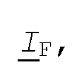
Z1L = R1L + jX1L is the impedance of the whole line for the positive or the negative sequence, respectively, Z0L = R0L + jX0L is the impedance of the whole line for the zero sequence and /F is the total fault current flowing through the fault resistance. The determination of the total fault current JF follows .
Table 1. Weighting coefficients for composing fault loop signals as defined in equations (2) and (3)
Figure imgf000014_0001
a = exp(j2 /3); J = V3T
In equation (1) there are two unknowns: the distance to fault d and the fault resistance RF . Resolving equation (1) into 5 the real and imaginary parts yields: realQ/Ap)-Jreal(Z1L/Ap)-i?Freal(7F) =0 (4) imag(V Ap ) - d imag(Z1L / Ap ) - RΈ imag(7F ) = 0 ( 5 )
After elimination of the fault resistance RF one obtains the 10 solution for the distance to fault d in the following form:
_ real(VAp) imag(/F) -imag(YAp) real(/F) real(Z1L/Ap) imag(/F) -imag(Z1L/Ap) real(/F)
Having determined the distance to fault d with equation (6) one can calculate the fault resistance RF : lfre∑Λ(V_A )imag(/F)-<ireal(Z1L/Ap)imag(/F) imag(VA )real(/F)-<iimag(Z1L/Ap)real(7F;
-1^ Rp — — 1
2 ^ real(7F ) imag(/F ) real(7F ) imag(/F )
(7)
The terms real(Z1L/Ap) and imag(Z1L/Ap) from equation (6) can also be expressed as: 20 real(Z1L /Ap ) = R1L real(/ Ap ) - X1L imag(/Ap ) (8a) imag(Z1L/Ap) = X1L real(/Ap) + R1L imag(/Ap) ( 8b ) where it was taken into account that the positive sequence impedance of the line equals:
25 As a result of that, the equation (6) transforms to: d_ real(V Ap) imag(/F) - imag(VAp) real(/F)
[R1L real(/ Ap ) - X1L imag(/Ap )]imag(/F) - [x1L real(/Ap ) + R1L imag(/Ap )]real(/F) Determination of the total fault current JF
It is proposed to utilize the generalized fault model in the form of the following equation for determining the total fault current IF :
Figure imgf000016_0001
) where :
Lm ' LF2 I LFO are symmetrical components of the total fault current, where the subscript 1 denotes the positive, subscript 2 denotes the negative and subscript 0 denotes the zero sequence, respectively) , and aF1 , apj , aF0 are share coefficients, dependent on the fault type.
The particular sequence components /F1 , J_¥2 and /F0 of the total fault current IF are determined by the sum of the respective sequence components of currents from the line terminals A and B. At the right-hand side of the equations given below the first subscript, A or B, denotes the terminal, while the second subscript 1, 2 or 0 denotes again the respective sequence component:
Lm=Lκι+Uι (H)
Figure imgf000016_0002
Alternatively, the positive sequence component /F1 of the total fault current IF can be determined with the use of the superimposed incremental positive sequence currents ΔJAi and
ΔJBχ, where incremental means the difference between the corresponding post-fault and pre-fault values:
/F1=Δ/A1+Δ/B1 (14) It is known that the use of the positive sequence currents from the line terminals according to equation (11), IAi and IBI, for determining the total fault current IF according to equation (10) is affected by the pre-fault load flow.
Therefore, in such cases where the positive sequence currents are used, the fault location accuracy is deteriorated, especially significantly if a high fault resistance is involved. In contrast, the use of the negative and zero sequence components and of the superimposed positive sequence components is advantageous for assuring high accuracy of the fault location.
Fault location algorithm - use of distributed parameter model of the line
The transmission parameters of the line
Further, it is taken into account that in real life transmission lines the positive and negative sequence parameters are identical. Impedances for the positive and negative sequences in the considered circuit diagrams are distinguished by different subscripts, 1 for the positive sequence and 2 for the negative sequence, even though they are of identical values. In the further considerations, the following transmission parameters of the transmission line are utilized: γ =\Z_ΪLY_ΪL is the propagation constant of the line for the positive sequence,
Y1 = Y, is the propagation constant of the line for the negative sequence,
^ =γZ0LFQL is the propagation constant of the line for the zero sequence,
Zci
Figure imgf000017_0001
is the characteristic impedance of the line for the positive sequence,
ZLC2 i s the characteri st ic impedance of the l ine for the negative sequence,
Figure imgf000018_0001
is the characteristic impedance of the line for the zero sequence,
Z1L = R1L +)'O)1L11^ is the impedance of the line for the positive sequence given in units of /km,
ZL2L =Z_VL is the impedance of the line for the negative sequence given in units of /km, F1L = G1L +j&\C1L is the admittance of the line for the positive sequence given in units of S/km,
F2L =IL is the admittance of the line for the negative sequence given in units of S/km,
-^1L' -^LL' G1 IL' QL are the resistance, inductance, conductance and capacitance of the line for the positive or negative sequence per km line length, respectively,
Z_0L = R0L+]0\LOL is the impedance of the line for the zero sequence given in units of /km,
F0L = G0L +jύ\C0L is the admittance of the line for the zero sequence given in units of S/km,
^0L' A)L' ^OL' Q)L are resistance, inductance, conductance and capacitance of the line for the zero sequence per km line length, respectively, £ is the length of the line given in units of km Z1L=Z11/ is the impedance of the line for the positive sequence given in units of ,
Z2L=Z1L is the impedance of the line for the negative sequence given in units of and Z0L = Z_0L£ is the impedance of the line for the zero sequence given in units of
Figures 5-7 illustrate the distributed parameter models of the faulted transmission line for the respective sequences.
Formulation of the fault location algorithm with taking into account the distributed parameter line model
The distance to fault d according to equations (6) or (9) is determined under neglecting the shunt capacitances of the transmission line. In case of short lines, say up to 150 km, equations (6) and (9) are sufficient for achieving high accuracy of fault location. However, for longer lines the distributed parameter nature of the line has to be taken into account and the effect of the shunt capacitances has to be compensated for. The derivation of an according algorithm follows .
Again, the generalized fault loop model is applied for determining the distance to fault. In the considered case, the generalized model describing the fault loop seen from the terminal A is formulated as follows:
V_Fp(d)-RFLF=0 (15)
where : d is the unknown distance to fault given in units of pu, as seen from the terminal A, RF is the unknown fault path resistance,
Vp (d) is the fault loop voltage, composed according to the fault type, after analytic transfer from the terminal A to the fault point F, /F is the fault path current or total fault current.
The transferred fault loop voltage V_¥ (d) from equation (15) is composed as follows:
YFp (d) = a1VF1 + a2V_F2 + a0V_F0 ( 1 6 )
where : alr a2 , a0 are weighting coefficients dependent on the fault type, as outlined in Table 1.
Applying the distributed parameter model of the line, the symmetrical components of the voltages VΈ1, VΈ2 and VF0 from equation (16) are determined as follows:
Figure imgf000020_0001
Ym = YAI∞sh(γ2£d) - Zc2/A2ύnh(γ2£d) (18)
YF0 = VAO cosh(y0^) -Zc0/A0 ήnh(γo£d) (19)
where:
Y-Ai ' YA2> YAO are the symmetrical components of side A voltages, with the subscript 1 denoting the positive sequence component, subscript 2 the negative sequence component and subscript 0 the zero sequence component, and LAI r LA2> LAO are the symmetrical components of side A currents .
The other parameters used in equations (17) -(19) are defined above . In order to solve equation (15), the total fault current ^TF is needed. Determination of the total fault current JF
The derivation of the positive sequence IFi of the total fault current I_F is presented below.
According to the distributed parameter model of the line for the positive sequence, Figure 5, one obtains after considering the faulted line section from terminal A to fault F:
Figure imgf000021_0001
Figure imgf000021_0004
Considering the other line section between fault F and terminal B, one obtains the following equation for the positive sequence of the remote current:
Figure imgf000021_0002
From equation (22) results that the positive sequence I_Έ1 of the total fault current IF is expressed as:
Figure imgf000021_0003
where :
Figure imgf000021_0005
Substituting VF1 by equation (20) and ^TAFI by equation (21), it is obtained:
Figure imgf000022_0001
Rearranging equation (A3) results in:
Figure imgf000022_0002
In general, hyperbolic functions can be expressed as:
sinh(x + y) = sinh(x)cosh(y) + sinh(x)cosh(y) ( A5 ) cosh(x + y) = sinh(x)sinh(y) + cosh(x)cosh(y) ( A6 )
Applying equations (A5)-(A6) for shortening of equation (A4] the following equation for the positive sequence IF1 of the total fault current IF is obtained:
Figure imgf000022_0003
where :
Figure imgf000022_0004
It is worth to notice that equations (23) -(24) can be linearized by taking into account that:
Figure imgf000022_0006
Figure imgf000022_0005
where : x = γl or x = γ £(l-d) according to figure 5.
Applying equations (A7)-(A8) to equations (23) -(24) results in obtaining the linearized equation for the positive sequence _IFi of the total fault current I_F :
Figure imgf000023_0001
The linearized equation (A9) can be utilized for starting iterative calculations of the distance to fault d.
Substituting equations (20) -(21) into equation (22) and after manipulations on hyperbolic functions as described above, the following equation is obtained for the positive sequence I_F1 of the total fault current IF :
Figure imgf000023_0002
where :
Figure imgf000023_0003
Analogously, for the negative sequence I_F2 of the total fault current ^TF it is obtained:
Figure imgf000023_0004
where :
M2 = / A2 cosh(^2^) + /B2 ^-EA2 sinh(72^) ( 26 ;
ZLC2 For the zero sequence I_F0 of the total fault current I_F it is obtained:
M0
/pn=" (27;
∞sh(γoe(l-d))
where :
Mo = ZAO Y_ Ao sinh(γo£) ( 28 ;
Figure imgf000024_0001
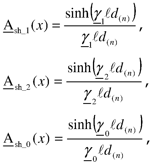
Utilizing the generalized fault model in the form of the equation (15) requires selecting the share coefficients aF1 , aK and aF0. In the case when the fault location algorithm takes into account the distributed parameter model of the line, the selection of the share coefficients differs from the case when the fault location algorithm takes into account the lumped model of the transmission line. This is so, because in the case of the distributed parameter model the sequence components of the total fault current according to equations (23) -(28) are dependent on the parameters of the transmission line γ and ZC1 , where the subscript i=l, 2 or 0 denotes the type of the symmetrical component. Namely, for the zero sequence component IF0 of the total fault current IF, the parameters of the line for the zero sequence Lγ-Q and ZicO are involved in equations (27) -(28) and it is worth to realize that these parameters are considered to be to some extent uncertain parameters. Therefore it is advantageous to explore the freedom in selecting the share coefficients in such a way that the zero sequence is excluded, i.e. the corresponding share coefficient is chosen to be equal to zero: aF0=0. In all further considerations exclusion of the zero sequence components is applied. As a result, the total fault current JF is now determined as: LF -<-.F1/F1 +Sp2Zp2 (29:
There are two characteristic sets, among others possible, of the share coefficients for the phase-to-ground and phase-to- phase faults, as outlined in Table 2.
Table 2. Two alternative sets of share coefficients for phase-to-ground faults and phase-to-phase faults
Figure imgf000025_0001
In contrast to the above fault types, another situation arises for the remaining fault types, phase-to-phase-to- ground and three phase symmetrical faults. This is so, since for these remaining faults there is no alternative sets of the share coefficients for the positive and the negative sequence - see Table 3. Table 3. Set of share coefficients for phase-to-phase-to- ground faults and three phase faults.
Figure imgf000026_0004
The fault loop voltage VFp(d), which is composed according to the fault type of Table 1 and analytically transferred from the terminal A to the fault point F, can be rewritten, starting from the generalized fault loop model (15) and taking into account equations (16) -(19):
1(EAi
Figure imgf000026_0002
-Zci/Ai smh(γ.£d)) :30)
Figure imgf000026_0001
Taking into account that the zero sequence component _JFo of the total fault current I_F is excluded according to equation (29), the generalized fault loop model (15) can be rewritten as follows:
:3i:
Figure imgf000026_0003
The obtained generalized fault loop model (31) can be solved by using numerical methods for solving a set of non-linear equations. In this case there are two unknowns which are the distance to fault d and the fault resistance RF . For example, the Newton-Raphson method can be applied for that. However, in order to make the calculations somehow simpler it is proposed to use the simplified models of the faulted transmission line as can be seen in Figures 8 - 10. Using these models, results in simple calculations for determining the distance to fault d.
According to the simplified models from Figures 8 - 10 the following generalized fault loop model, seen from the terminal A, can be formulated:
VAp - d(n+l)AVp(d(n)) -RF/F(d(n)) = 0 (32)
where : n denotes the previous iteration step, n+1 denotes the current iteration step,
J(J1+1) is the value of the distance to fault obtained as the result of performing the current iteration step, d(a) is the value of the distance to fault obtained in the previous iteration step, which when starting the iterative calculations is obtained from the fault location algorithm for the lumped model of the transmission line according to equation (6) or (9) .
The fault loop voltage VRp from equation (32) is composed of symmetrical components V_A1, VR2 and VR3, with using the weighting coefficients outlined in Table 1:
Figure imgf000027_0001
The voltage drop d(a+l)^y_p{d(n)) across the faulted line section between terminal A and fault F, derived from the generalized fault loop model (32), involves the distance to fault d{n+l) of the current iteration step and the fault loop quantity
The quantity is determined with a simplification, namely
Figure imgf000028_0002
with taking into account the impedance and admittance parameters of the faulted line section between terminal A and fault F, considered as being of the length equal to the value of the previous value of the distance to fault d{n) :
Figure imgf000028_0003
The symmetrical components of the currents
Figure imgf000028_0004
(see Figures 8 - 10) are used for calculation of the fault loop quantity according to equation (34) . The currents
Figure imgf000028_0005
are obtained by deducing the respective
Figure imgf000028_0006
shunt currents:
Figure imgf000028_0007
where :
Figure imgf000028_0001
taah(θ.5ridj
Figure imgf000029_0001
The total fault current after taking into account that
Figure imgf000029_0008
the zero sequence component is excluded, can be expressed as follows :
Figure imgf000029_0003
with the positive sequence of the total fault current I_F:
Figure imgf000029_0007
Figure imgf000029_0004
where :
Figure imgf000029_0005
and with the negative sequence
Figure imgf000029_0009
of the total fault current IF:
Figure imgf000029_0002
where :
Figure imgf000029_0006
The equation (32) with the two unknowns
Figure imgf000029_0010
can be solved by resolving it into the real and imaginary parts: real(yAp) - J(n+1)real(Δyp (J(π))) - RFreal(/F(Jw )) = 0 ( 43 ) imag(y Ap ) - d(n+1)imag(ΔV_ p (d(n) )) - RFimag(/F ( d(n) )) = 0 ( 44 )
By el iminat ing the fault res i stance RF , one obtains the equat ion for the di stance to fault d(n+i) of the current iterat ion step :
d real(V Ap ) imag(/F (d(n) )) - imag(y Ap ) real(/F (d(n) ))
(n+1) real(Δy p (d{n) )) imag(/F (d{n) )) - imag(Δy p (d{n) )) real(/F (d{n) ))
Iterative calculations have to be performed for a pre-defined number of iteration steps or until the pre-defined convergence is achieved, i.e. until the difference between the value of the distance to fault of the current iteration step d(n+i) and the value of the distance to fault of the previous iteration step dn is less than a pre-defined threshold value, . However, in practice performing a single iteration only is usually sufficient.
Having determined the distance to fault according to equation (45) one can calculate the fault resistance RF from equations (43) -(44), analogously as in the case of the lumped model of the line according to equation (7) .
The method to determine the distance to fault outlined above is especially suitable to be incorporated as an added feature into a current differential relay. When the current differential relay is applied to protect a two-terminal line, it utilizes the phase currents measured synchronously at both line terminals for the protection purposes. Therefore, in order to incorporate the fault location function additionally to the protection function itself, the local phase voltages, i.e. the phase voltages from the terminal where the differential relay is installed, which is presumed to be the terminal A in the further considerations, have to be supplied to the relay. In this way the differential relay equipped with the fault location feature can identify the fault not only in terms whether it occurred within the zone or outside it, which is already part of the known differential relay principle, but also more precisely in terms of determining the exact distance from the local line terminal. This additional feature of the current differential relay can for example be used to support and simplify inspection and repair of a faulty transmission or distribution line.

Claims

Claims
1. A method for locating a fault in a two-terminal power transmission or distribution line comprising the steps of: - receiving measurements of three phase currents (IA_a, IA_b, I_R_C; Iβ_ar Iβ_br Iβ_c) from each of the two terminals (A; B) ,
- receiving measurements of three phase voltages (VR_a, VR_h, VR_C) from one of the two terminals (A) ,
- receiving transmission parameters (ZpL, Z1L,' Z_r OLΛ Z_r IL, ∑' OLΛ Y' iL, 1) of the line,
- receiving the fault type, characterized by
- determining the symmetrical current and voltage components
(IA1, IA2, I_AO,' IBI, IB2, IBO; VR1, VA2, VA0) corresponding to the phase currents (I_A_a, I_R_b, I_R_C; Iβ_ar Iβ_b, IB_C) and phase voltages ( VA_a, VA_b, VA_C) ,
- determining the fault loop voltage (VRp) seen from the one of the two terminals (A) based on the corresponding symmetrical voltage components (VR1, VR2, VRo) and on the fault type,
- determining the fault loop current (IAP) seen from the one of the two terminals (A) based on the symmetrical current components (IAi, I_A2, I_A0) of the one of the two terminals (A) , on the transmission parameters (Z^ohr Z1L) and on the fault type,
- determining the total fault current (^F) based on the symmetrical current components (IAi, I_R2, I_R0; I_B1, I_B2, I_B0) and on the fault type,
- determining the distance to fault (d) seen from the one of the two terminals (A) based on the fault loop voltage ( VkP) , on the fault loop current [IA9) and on the total fault current (I_F) ,
- outputting the distance to fault (d) to an output interface .
2. A method according to claim 1, where the distance to fault (d) is determined according to real(V Ap ) imag( / F ) - imag(V Ap ) real(/ F ) real(Z1L/Ap) imag(/F) -imag(Z1L/Ap) real(/F)
3. A method according to claim 1 or 2, further comprising an iteration which starts from the already determined distance to fault (d(n)=d) and outputs the distance to fault (d(n+i)) determined in the last iteration step after a predefined number of iteration steps (n+1) are reached or after a predefined convergence of the distance to fault is achieved, where each iteration step (n) comprises the steps:
- determining a fault loop quantity (Av9) qualifying the voltage drop (d(n+i)-ΔVp) between the one of the two terminals (A) and the fault (F) based on the symmetrical current and voltage components (I_AI, IR2, _^AO; VR1, YAII YAO) of the one of the two terminals (A) , on the transmission parameters {Z_r 01, Z_r 1L, Y_' 01, Y_' 1L, 1), on the fault type and on a former distance to fault (d(n)) determined in a former iteration step (n) , - determining an iterative total fault current (I_F(d{n))) based on the symmetrical current and voltage components
(^Al i I_A2 ι ^AO A ^Bl i _^B2 1 IβO ϊ YRI r X_A2 r X_Aθ ) i On the transmission parameters [Z/ OL, Z_' IL, Yr OL, Yr IL, 1) , on the fault type and on a former distance to fault (d(ri)) determined in a former iteration step (n) , - determining the distance to fault (d(n+i)) based on the fault loop voltage ( VAp) , on the fault loop quantity (ΔVp) and on the iterative total fault current (^TF (d(n) ) ) .
4. A method according to claim 3, where the distance to fault (d(n+i)) of the current iteration step (n+1) is determined according to real(V Ap ) imag(/F (d{n) )) - imag(V Ap ) real(/F (d{n) ))
*(n+l) real(ΔV_(d(n))) imag(/F(d(n))) -imag(ΔV_(d(n))) real(/F(d(n)))
5. A method according to claim 3 or 4, where the iterative total fault current (^F(d(n))) is determined by eliminating its zero sequence current component (^2) •
6. A device for locating a fault in a two-terminal power transmission or distribution line comprising
- a processing unit,
- an output interface connected to the processing unit,
- means to receive measurements of three phase currents (IA_a, IA_b, ^A_C; Iβ_ar Iβ_br Iβ_c) from each of the two terminals (A; B) connected to the processing unit,
- means to receive measurements of three phase voltages {VR_a, Y_A_b, Y_A_C) from one of the two terminals (A) connected to the processing unit,
- means to receive transmission parameters {Z^ohr Z_IL; Z_r OL, 7/ iL, Y' OL/- Y' iLr 1) of the line connected to the processing unit,
- means to receive the fault type connected to the processing unit, characterized in that the processing unit carries out the method according to at least one of the claims 1 to 3.
7. A device according to claim 6, where the device is a current differential relay to protect the transmission or distribution line.
8. A computer program comprising computer program code means for carrying out the steps of the method according to at least one of the claims 1 - 5.
PCT/EP2006/066229 2006-01-12 2006-09-11 Method and device for fault location in a two-terminal transmission or distribution power line Ceased WO2007079990A1 (en)

Priority Applications (4)

Application Number Priority Date Filing Date Title
US12/160,552 US8183871B2 (en) 2006-01-12 2006-09-11 Method and device for fault location in a two-terminal transmission or distribution power line
CN2006800508915A CN101356444B (en) 2006-01-12 2006-09-11 Method and device for fault location in a two-terminal transmission or distribution power line
EP06793410.9A EP1971869B1 (en) 2006-01-12 2006-09-11 Method and device for fault location in a two-terminal transmission or distribution power line
HK09104390.9A HK1128766B (en) 2006-01-12 2006-09-11 Method and device for fault location in a two-terminal transmission or distribution power line

Applications Claiming Priority (2)

Application Number Priority Date Filing Date Title
SE0600119-2 2006-01-12
SE0600119A SE528863C2 (en) 2006-01-12 2006-01-12 Two-terminal power transmission and distribution line fault locating method for use in factory, involves receiving measurements of three phase currents from two terminals, and receiving measurements of three phase voltages

Publications (1)

Publication Number Publication Date
WO2007079990A1 true WO2007079990A1 (en) 2007-07-19

Family

ID=37668136

Family Applications (1)

Application Number Title Priority Date Filing Date
PCT/EP2006/066229 Ceased WO2007079990A1 (en) 2006-01-12 2006-09-11 Method and device for fault location in a two-terminal transmission or distribution power line

Country Status (6)

Country Link
US (1) US8183871B2 (en)
EP (1) EP1971869B1 (en)
CN (1) CN101356444B (en)
RU (1) RU2419802C2 (en)
SE (1) SE528863C2 (en)
WO (1) WO2007079990A1 (en)

Cited By (11)

* Cited by examiner, † Cited by third party
Publication number Priority date Publication date Assignee Title
EP2017632A1 (en) 2007-07-19 2009-01-21 ABB Research Ltd. Method for fault location in uncompensated power lines with two-end unsynchronized measurement
EP2045610A1 (en) * 2007-10-05 2009-04-08 Schneider Electric Industries SAS Location of a fault in a medium-voltage public distribution system
CN101917055A (en) * 2010-08-05 2010-12-15 华北电力大学 A wide-area backup protection method based on branch closeness
FR2947054A1 (en) * 2009-06-23 2010-12-24 Schneider Electric Ind Sas DEVICE AND METHOD FOR INDICATING ELECTRICAL DEFECTS, ASSEMBLY AND ELECTRICAL TABLE COMPRISING SUCH A DEVICE
CN102099698A (en) * 2008-07-18 2011-06-15 Abb技术有限公司 Method and device for fault location of series-compensated transmission line
US8081002B2 (en) * 2008-04-29 2011-12-20 Abb Technology Ag Apparatus and method for determining location of phase-to-phase fault or three-phase fault
CN102545176A (en) * 2012-02-17 2012-07-04 黑龙江省电力有限公司 Current transformer (CT) current orientation method for wide-area differential combinations
CN103278736A (en) * 2013-04-12 2013-09-04 南方电网科学研究院有限责任公司 A lightning automatic query diagnosis and diagnosis result release method for tripped lines
RU2508556C1 (en) * 2012-10-24 2014-02-27 Федеральное государственное бюджетное образовательное учреждение высшего профессионального образования "Иркутский государственный технический университет" (ФГБОУ ВПО "ИрГТУ") Method for determination of short-circuit place on overhead transmission line under nonsynchronised measurements on its both ends
WO2019166903A1 (en) * 2018-02-28 2019-09-06 Abb Schweiz Ag Method and device for fault location in a two-terminal transmission system
RU2837362C1 (en) * 2024-07-18 2025-03-31 Федеральное государственное бюджетное образовательное учреждение высшего образования "Петербургский государственный университет путей сообщения Императора Александра I" Method of determining nature of fault in electrified railway power supply system

Families Citing this family (66)

* Cited by examiner, † Cited by third party
Publication number Priority date Publication date Assignee Title
GB2469773B (en) * 2008-02-22 2012-09-12 Hewlett Packard Development Co Display housing with slot for receiving peripheral devices
WO2011127967A1 (en) * 2010-04-13 2011-10-20 Abb Technology Ag Fault wave arrival determination
US8525522B2 (en) 2010-04-21 2013-09-03 Schweitzer Engineering Laboratories Inc Fault location in electric power delivery systems
US8942954B2 (en) * 2010-09-16 2015-01-27 Schweitzer Engineering Laboratories, Inc. Fault location in a non-homogeneous electric power line
CN102081132B (en) * 2010-12-04 2013-01-16 西南交通大学 Two-end distance measuring method of transmission line fault under dynamic condition
CN102331548B (en) * 2011-05-31 2014-02-26 重庆大学 Single-phase earth fault positioning method for distribution network cable
RU2472169C1 (en) * 2011-05-31 2013-01-10 Открытое Акционерное Общество "Федеральная Сетевая Компания Единой Энергетической Системы" (Оао "Фск Еэс") Method to detect distance to area of damage on power transmission line
CN102255290B (en) * 2011-06-27 2014-05-07 华北电力大学 Current adaptive protecting method
US20130046411A1 (en) * 2011-08-15 2013-02-21 Siemens Corporation Electric Vehicle Load Management
US8922652B2 (en) 2011-08-29 2014-12-30 General Electric Company Systems and methods for locating faults in a power system
US8791704B2 (en) 2011-10-11 2014-07-29 Schweitzer Engineering Laboratories Inc. Fault-type identification for electric power delivery systems
RU2492493C2 (en) * 2011-11-23 2013-09-10 Общество с ограниченной ответственностью "Исследовательский центр "Бреслер" Method of determining point of fault of multi-wire electric power network with two-way observation
RU2505826C2 (en) * 2012-01-11 2014-01-27 Общество с ограниченной ответственностью "Исследовательский центр "Бреслер" Method of determining point and nature of damage to multiwire power grid
RU2505825C2 (en) * 2012-02-17 2014-01-27 Общество с ограниченной ответственностью "Исследовательский центр "Бреслер" Method of determining points of double short-circuit in multiwire power grid
RU2505827C1 (en) * 2012-05-23 2014-01-27 Федеральное государственное бюджетное образовательное учреждение высшего профессионального образования "Иркутский государственный технический университет" (ФГБОУ ВПО "ИрГТУ") Method of determining point of short-circuit on overhead power line from measurements at two ends thereof (versions)
CN102694375B (en) * 2012-06-11 2014-07-30 国家电网公司 Ultra high-voltage alternating current transmission line protection method based on all-component differential coefficient matrix
RU2504792C1 (en) * 2012-07-17 2014-01-20 Федеральное государственное бюджетное образовательное учреждение высшего профессионального образования "Национальный исследовательский Томский политехнический университет" Method for determination of short-circuit location at overhead transmission lines against arrays of instantaneous current and voltage values
RU2508555C1 (en) * 2012-10-05 2014-02-27 Федеральное государственное бюджетное образовательное учреждение высшего профессионального образования "Национальный исследовательский Томский политехнический университет" Method for determining place of phase loss of overhead transmission line
CN103197204B (en) * 2013-04-07 2015-04-29 山东电力集团公司德州供电公司 Mixed type method of multi-terminal circuit fault location
US9835673B2 (en) * 2013-04-12 2017-12-05 Mitsubishi Electric Research Laboratories, Inc. Method for analyzing faults in ungrounded power distribution systems
CN103323739B (en) * 2013-05-19 2016-06-29 国家电网公司 Based on distribution parameter measurement impedance magnitude characteristic circuit inter-phase fault single-end ranging
CN103293444B (en) * 2013-05-19 2016-03-02 国家电网公司 The line single-phase earth fault single-terminal location method of anti-transition resistance and load current impact
CN103293442B (en) * 2013-05-19 2016-06-29 国家电网公司 Residual voltage distribution character is utilized to realize line single-phase earth fault single-terminal location method
RU2540443C1 (en) * 2013-07-23 2015-02-10 Федеральное государственное бюджетное образовательное учреждение высшего профессионального образования "Национальный исследовательский Томский политехнический университет" Method for determining place of failure on overhead transmission line
RU2542337C1 (en) * 2013-09-13 2015-02-20 Общество с ограниченной ответственностью "Исследовательский центр "Бреслер" Method of determining of point of shorting of electric power transmission line with two-way observation
RU2542331C1 (en) * 2013-10-02 2015-02-20 Общество с ограниченной ответственностью "Исследовательский центр "Бреслер" Method of determining of point of shorting of electric power transmission line with two-way observation
CN103743996B (en) * 2013-10-15 2016-06-22 昆明理工大学 A kind of based on π type equivalent circuit direct current grounding pole circuit fault distance measurement
CN103792465B (en) * 2013-12-24 2016-05-04 中国矿业大学 A kind of method of the range finding of the one-phase earthing failure in electric distribution network based on residual voltage
CN103837800A (en) * 2014-03-18 2014-06-04 国家电网公司 Method for locating direct-current transmission line unipolar grounding fault
RU2568680C1 (en) * 2014-09-09 2015-11-20 Общество с ограниченной ответственностью "Исследовательский центр "Бреслер" Method for determining location of feeder short-circuiting with two-way observation
DE102014218764A1 (en) * 2014-09-18 2016-03-24 Siemens Aktiengesellschaft Power transmission system and method of operating a power transmission system
FR3026492B1 (en) * 2014-09-29 2016-10-28 Schneider Electric Ind Sas DIRECTIONAL DETECTION OF EARTH FAULT IN AN ELECTRICAL DISTRIBUTION NETWORK
CN104459465B (en) * 2014-11-26 2017-09-01 国家电网公司 A Fault Section Locating Method for Distribution Network Containing Distributed Power
CN104898017B (en) * 2015-04-28 2017-12-15 国家电网公司 Distribution network line fault Section Location based on Euclidean distance
RU2586438C1 (en) * 2015-04-29 2016-06-10 Степан Георгиевич Тигунцев Method of determining location of short circuit at long power line of voltage 220 kv and higher
CN104808114B (en) * 2015-05-04 2017-12-29 中国矿业大学 The earth fault line selection method of wide area zero sequence spread voltage feature
RU2605491C1 (en) * 2015-07-01 2016-12-20 Степан Георгиевич Тигунцев Method of determining short circuit location on overhead transmission line by measurements from two ends of line considering difference in longitudinal and transverse phase and interphase parameters of line
RU2593409C1 (en) * 2015-07-13 2016-08-10 Степан Георгиевич Тигунцев Method of determining location of short circuit at long power line with spur line
RU2605558C1 (en) * 2015-07-16 2016-12-20 Степан Георгиевич Тигунцев Method of determining short circuit location on overhead transmission line with lightning protection cable by measurements from two ends of line considering difference in longitudinal and transverse phase and interphase parameters of line
RU2593407C1 (en) * 2015-07-22 2016-08-10 Степан Георгиевич Тигунцев Method for determining location of short circuit with simultaneous break of wire at overhead transmission line
CN105223473A (en) * 2015-11-07 2016-01-06 国网山东平度市供电公司 A kind of stage high-tension circuit trouble hunting device
RU2610852C1 (en) * 2015-12-18 2017-02-16 федеральное государственное бюджетное образовательное учреждение высшего образования "Иркутский национальный исследовательский технический университет" (ФГБОУ ВО "ИРНИТУ") Method of short circuit place determination in overhead power transmission line with calculated synchronisation of measurements at its both ends
RU2620193C1 (en) * 2015-12-18 2017-05-23 Степан Георгиевич Тигунцев Method of determining short-short location in overhead power line with distributed parameters
RU2623180C1 (en) * 2015-12-30 2017-06-22 Степан Георгиевич Тигунцев Method of determining the short circuit spot on multi-chain with earth-wires, grounded at anchor supports, three-phase electric transmission air-line with distributed parameters
RU2639590C2 (en) * 2016-05-04 2017-12-21 федеральное государственное бюджетное образовательное учреждение высшего образования "Нижегородский государственный технический университет им. Р.Е. Алексеева" (НГТУ) Method for determining location of short circuit on overhead line by arrays of instantaneous values of currents and voltages
RU2637716C1 (en) * 2016-09-07 2017-12-06 Степан Георгиевич Тигунцев Method for determination of short circuit spot on long power transmission line with adjustment of line characteristic
ES2989644T3 (en) * 2017-04-11 2024-11-27 Aclara Tech Llc Floating neutral detection and location system and procedures
WO2019186490A1 (en) 2018-03-31 2019-10-03 Abb Schweiz Ag Method and device for protection in a multi-terminal power transmission system
CN108508326B (en) * 2018-04-26 2020-03-17 西南交通大学 Transmission line fault detection method based on positive sequence current fault component
US10656197B2 (en) * 2018-08-23 2020-05-19 Schweitzer Engineering Laboratories, Inc. Accurate fault location method based on local measurements and remote currents
US11150290B2 (en) 2018-08-23 2021-10-19 Schweitzer Engineering Laboratories, Inc. Accurate fault location method based on local and remote voltages and currents
US10859639B2 (en) 2018-10-02 2020-12-08 Schweitzer Engineering Laboratories, Inc. Fault-type identification in an electric power delivery system using composite signals
RU2700370C1 (en) * 2018-12-26 2019-09-16 федеральное государственное бюджетное образовательное учреждение высшего образования "Ивановский государственный энергетический университет имени В.И. Ленина" (ИГЭУ) Method for remote determination of short-circuit point
EP3726681A1 (en) * 2019-04-19 2020-10-21 Supergrid Institute Transient based method for identifying faults in a high / medium voltage electric power transmission system, fault identification module and power transmission system
CN110492449B (en) * 2019-07-16 2022-04-15 中国电力科学研究院有限公司 Time-limit-variable distance protection timing method and device based on same-tower multi-circuit line
RU2720949C1 (en) * 2019-11-26 2020-05-15 Михаил Владимирович Мартынов Method for interval determination of power transmission line fault location
RU2731657C1 (en) * 2019-12-02 2020-09-07 федеральное государственное бюджетное образовательное учреждение высшего образования "Ивановский государственный энергетический университет имени В.И. Ленина" (ИГЭУ) Method for remote determination of short-circuit place on power transmission line
US11271389B2 (en) * 2020-06-24 2022-03-08 Schweitzer Engineering Laboratories, Inc. Distance protection using supervised sequence currents and voltages for electric power delivery systems
US11592498B2 (en) 2020-10-02 2023-02-28 Schweitzer Engineering Laboratories, Inc. Multi-phase fault identification in capacitor banks
CN112505488B (en) * 2020-12-07 2023-05-26 云南电网有限责任公司 Double-end fault wave recording and distance measuring method for power transmission line
US11808824B2 (en) 2021-03-17 2023-11-07 Schweitzer Engineering Laboratories, Inc. Systems and methods to identify open phases of a capacitor bank
US12313701B2 (en) 2021-03-17 2025-05-27 Schweitzer Engineering Laboratories, Inc. Capacitor bank fault detection and identification
CN114002544B (en) * 2021-10-11 2024-03-08 北京四方继保工程技术有限公司 Multi-terminal line protection fault positioning and ranging method
WO2025045350A1 (en) * 2023-08-29 2025-03-06 Technische Universität Graz Distance relay, method and device for determining a fault distance in a power transmission line
EP4729956A1 (en) * 2024-10-16 2026-04-22 Hitachi Energy Ltd Method, device, and storage medium for fault location on collector grid networks
CN120891330B (en) * 2025-09-30 2026-01-09 上海埃因电线电缆有限公司 A cable fault detection method based on data transmission current differential signal

Citations (2)

* Cited by examiner, † Cited by third party
Publication number Priority date Publication date Assignee Title
US4559491A (en) * 1982-09-14 1985-12-17 Asea Aktiebolag Method and device for locating a fault point on a three-phase power transmission line
WO2003044547A1 (en) 2001-11-23 2003-05-30 Abb Ab Fault location using measurements from two ends of a line

Family Cites Families (5)

* Cited by examiner, † Cited by third party
Publication number Priority date Publication date Assignee Title
RU2107304C1 (en) * 1995-11-13 1998-03-20 Чувашский государственный университет им.И.Н.Ульянова Method of determination of damaged place in power line with two-way supply
SE513492C2 (en) * 1997-12-22 2000-09-18 Abb Ab Method and apparatus for locating faults on a capacitor compensated power line with capacitor
JP2000214210A (en) * 1999-01-20 2000-08-04 Toshiba Corp Accident point location device
US6256592B1 (en) * 1999-02-24 2001-07-03 Schweitzer Engineering Laboratories, Inc. Multi-ended fault location system
RU2189606C1 (en) * 2001-04-16 2002-09-20 Фигурнов Евгений Петрович Procedure determining distance to short-circuit point in ac contact network and device for its realization

Patent Citations (2)

* Cited by examiner, † Cited by third party
Publication number Priority date Publication date Assignee Title
US4559491A (en) * 1982-09-14 1985-12-17 Asea Aktiebolag Method and device for locating a fault point on a three-phase power transmission line
WO2003044547A1 (en) 2001-11-23 2003-05-30 Abb Ab Fault location using measurements from two ends of a line

Non-Patent Citations (5)

* Cited by examiner, † Cited by third party
Title
"A two-end method of fault location immune to saturation of current transformers", DEVELOPMENTS IN POWER SYSTEM PROTECTION PROCEEDINGS, 2004, pages 172 - 175
BRAHMA S M ET AL: "Fault Location on a Transmission Line Using Synchronized Voltage Measurements", IEEE TRANSACTIONS ON POWER DELIVERY, IEEE SERVICE CENTER, NEW YORK, NY, US, vol. 19, no. 4, October 2004 (2004-10-01), pages 1619 - 1622, XP011119538, ISSN: 0885-8977 *
DAMIR NOVOSEL ET AL: "UNSYNCHRONIZED TWO-TERMINAL FAULT LOCATION ESTIMATION", IEEE TRANSACTIONS ON POWER DELIVERY, IEEE SERVICE CENTER, NEW YORK, NY, US, vol. 11, no. 1, January 1996 (1996-01-01), pages 130 - 138, XP011049074, ISSN: 0885-8977 *
I. ZAMORA ET AL.: "Fault location on two-terminal transmission lines based on voltages", IEE PROC. GENER. TRANSM. DISTRIB., vol. 143, no. 1, 1996, pages 1 - 6
SUKUMAR M. BRAHMA; ADLY A. GIRGIS: "Fault Location on a Transmission Line Using Synchronized Voltage Measurements", IEEE TRANSACTIONS ON POWER DELIVERY, vol. 19, 4 October 2004 (2004-10-04), pages 1619 - 1622

Cited By (19)

* Cited by examiner, † Cited by third party
Publication number Priority date Publication date Assignee Title
US8207743B2 (en) 2007-07-19 2012-06-26 Abb Research Ltd. Method for fault location in uncompensated power lines with two-end unsynchronized measurement
WO2009010169A1 (en) * 2007-07-19 2009-01-22 Abb Research Ltd Method for fault location in uncompensated power lines with two-end unsynchronized measurement
EP2017632A1 (en) 2007-07-19 2009-01-21 ABB Research Ltd. Method for fault location in uncompensated power lines with two-end unsynchronized measurement
EP2045610A1 (en) * 2007-10-05 2009-04-08 Schneider Electric Industries SAS Location of a fault in a medium-voltage public distribution system
FR2922028A1 (en) * 2007-10-05 2009-04-10 Schneider Electric Ind Sas LOCATING A DEFECT IN A MEDIUM VOLTAGE PUBLIC DISTRIBUTION NETWORK
US8081002B2 (en) * 2008-04-29 2011-12-20 Abb Technology Ag Apparatus and method for determining location of phase-to-phase fault or three-phase fault
CN102099698A (en) * 2008-07-18 2011-06-15 Abb技术有限公司 Method and device for fault location of series-compensated transmission line
US20110178741A1 (en) * 2008-07-18 2011-07-21 Murari Saha Method and device for fault location of series-compensated transmission line
US9182441B2 (en) 2008-07-18 2015-11-10 Abb Technology Ag Method and device for fault location of series-compensated transmission line
CN102099698B (en) * 2008-07-18 2015-06-10 Abb技术有限公司 Method and device for fault location of series-compensated transmission line
EP2267465A1 (en) * 2009-06-23 2010-12-29 Schneider Electric Industries SAS Device and method for indicating electrical faults, assembly and electric board comprising such a device
AU2010202580B2 (en) * 2009-06-23 2014-08-14 Schneider Electric Industries Sas Device and method for signalling electric faults, unit and electric panel comprising such a device
FR2947054A1 (en) * 2009-06-23 2010-12-24 Schneider Electric Ind Sas DEVICE AND METHOD FOR INDICATING ELECTRICAL DEFECTS, ASSEMBLY AND ELECTRICAL TABLE COMPRISING SUCH A DEVICE
CN101917055A (en) * 2010-08-05 2010-12-15 华北电力大学 A wide-area backup protection method based on branch closeness
CN102545176A (en) * 2012-02-17 2012-07-04 黑龙江省电力有限公司 Current transformer (CT) current orientation method for wide-area differential combinations
RU2508556C1 (en) * 2012-10-24 2014-02-27 Федеральное государственное бюджетное образовательное учреждение высшего профессионального образования "Иркутский государственный технический университет" (ФГБОУ ВПО "ИрГТУ") Method for determination of short-circuit place on overhead transmission line under nonsynchronised measurements on its both ends
CN103278736A (en) * 2013-04-12 2013-09-04 南方电网科学研究院有限责任公司 A lightning automatic query diagnosis and diagnosis result release method for tripped lines
WO2019166903A1 (en) * 2018-02-28 2019-09-06 Abb Schweiz Ag Method and device for fault location in a two-terminal transmission system
RU2837362C1 (en) * 2024-07-18 2025-03-31 Федеральное государственное бюджетное образовательное учреждение высшего образования "Петербургский государственный университет путей сообщения Императора Александра I" Method of determining nature of fault in electrified railway power supply system

Also Published As

Publication number Publication date
EP1971869A1 (en) 2008-09-24
US8183871B2 (en) 2012-05-22
RU2419802C2 (en) 2011-05-27
SE0600119L (en) 2007-02-27
US20100277181A1 (en) 2010-11-04
CN101356444A (en) 2009-01-28
EP1971869B1 (en) 2014-04-23
HK1128766A1 (en) 2009-12-31
RU2008133030A (en) 2010-02-20
CN101356444B (en) 2011-04-13
SE528863C2 (en) 2007-02-27

Similar Documents

Publication Publication Date Title
WO2007079990A1 (en) Method and device for fault location in a two-terminal transmission or distribution power line
US7286963B2 (en) Method and device for fault location on three terminal power line
US4996624A (en) Fault location method for radial transmission and distribution systems
Izykowski et al. Accurate noniterative fault-location algorithm utilizing two-end unsynchronized measurements
Novosel et al. Unsynchronized two-terminal fault location estimation
Izykowski et al. Accurate location of faults on power transmission lines with use of two-end unsynchronized measurements
US5929642A (en) Method of locating a fault in a predetermined monitoring region of a multiphase electric power transmission system
EP1724597B1 (en) System and method for determining location of phase-to-earth fault
EP1982395B1 (en) Method and adaptive distance protection relay for power transmission lines
EP2474076B1 (en) A method of fault phase selection and fault type determination
US6466031B1 (en) Systems and methods for locating faults on a transmission line with multiple tapped loads
Saha et al. Review of fault location techniques for distribution systems
Apostolopoulos et al. A novel algorithm for locating faults on transposed/untransposed transmission lines without utilizing line parameters
KR100350722B1 (en) Apparatus and method for locating fault distance in a power double circuit transmision line
WO2000050908A9 (en) Multi-ended fault location system
WO1995024014A2 (en) One-terminal data fault location system
AU9743401A (en) Systems and methods for locating faults on a transmission line with a single tapped load
US11035897B2 (en) Method and device for fault section identification in multi-terminal mixed lines
EP1870717B1 (en) System and method for determining phase-to-earth admittances of a three-phase electric line
Saha et al. Fault location method for MV cable network
WO2019166903A1 (en) Method and device for fault location in a two-terminal transmission system
Hänninen et al. Earth fault distance computation with fundamental frequency signals based on measurements in substation supply bay
Lima et al. Electrical power systems fault location with one-terminal data using estimated remote source impedance
de Pereira et al. Fault location in multitapped transmission lines using unsynchronized data and superposition theorem
Chen et al. Fast and accurate fault detection/location algorithms for double‐circuit/three‐terminal lines using phasor measurement units

Legal Events

Date Code Title Description
121 Ep: the epo has been informed by wipo that ep was designated in this application
WWE Wipo information: entry into national phase

Ref document number: 2006793410

Country of ref document: EP

WWE Wipo information: entry into national phase

Ref document number: 5561/DELNP/2008

Country of ref document: IN

WWE Wipo information: entry into national phase

Ref document number: 12160552

Country of ref document: US

WWE Wipo information: entry into national phase

Ref document number: 200680050891.5

Country of ref document: CN

NENP Non-entry into the national phase

Ref country code: DE

ENP Entry into the national phase

Ref document number: 2008133030

Country of ref document: RU

Kind code of ref document: A

WWP Wipo information: published in national office

Ref document number: 2006793410

Country of ref document: EP