WO2007104166A1 - Ophthalmological device and ophthalmological measuring method - Google Patents
Ophthalmological device and ophthalmological measuring method Download PDFInfo
- Publication number
- WO2007104166A1 WO2007104166A1 PCT/CH2006/000153 CH2006000153W WO2007104166A1 WO 2007104166 A1 WO2007104166 A1 WO 2007104166A1 CH 2006000153 W CH2006000153 W CH 2006000153W WO 2007104166 A1 WO2007104166 A1 WO 2007104166A1
- Authority
- WO
- WIPO (PCT)
- Prior art keywords
- image
- top view
- section
- eye
- comparative
- Prior art date
- Legal status (The legal status is an assumption and is not a legal conclusion. Google has not performed a legal analysis and makes no representation as to the accuracy of the status listed.)
- Ceased
Links
Classifications
-
- A—HUMAN NECESSITIES
- A61—MEDICAL OR VETERINARY SCIENCE; HYGIENE
- A61B—DIAGNOSIS; SURGERY; IDENTIFICATION
- A61B3/00—Apparatus for testing the eyes; Instruments for examining the eyes
- A61B3/10—Objective types, i.e. instruments for examining the eyes independent of the patients' perceptions or reactions
- A61B3/113—Objective types, i.e. instruments for examining the eyes independent of the patients' perceptions or reactions for determining or recording eye movement
-
- A—HUMAN NECESSITIES
- A61—MEDICAL OR VETERINARY SCIENCE; HYGIENE
- A61B—DIAGNOSIS; SURGERY; IDENTIFICATION
- A61B3/00—Apparatus for testing the eyes; Instruments for examining the eyes
- A61B3/10—Objective types, i.e. instruments for examining the eyes independent of the patients' perceptions or reactions
- A61B3/14—Arrangements specially adapted for eye photography
- A61B3/15—Arrangements specially adapted for eye photography with means for aligning, spacing or blocking spurious reflection ; with means for relaxing
- A61B3/152—Arrangements specially adapted for eye photography with means for aligning, spacing or blocking spurious reflection ; with means for relaxing for aligning
Definitions
- the present invention relates to an ophthalmological device and an ophthalmological measuring method. Specifically, the present invention relates to an ophthalmological device and an ophthalmological measuring method having a light projector projecting a beam of rays through a cross-sectional portion of an eye, image-capturing means disposed in Scheimpflug configuration with respect to the beam of rays and capturing in a first instrument position a cross-sectional image of at least a sub-area of the cross-sectional portion, and a motion driver moving the first image-capturing means to a second instrument position, at which second instrument position the first image- capturing means are disposed in Scheimpflug configuration with respect to the beam of rays.
- U.S. 5,404,884 are a method and a device for examining corneal tissue of a patient.
- a substantially planer laser beam with a slit-like profile is directed through a cross-sectional portion of the cornea.
- a cross-sectional image of the cornea is obtained. From a multiplicity of such cross-sectional images of the cornea, corneal haze, corneal thickness and corneal topography can be determined comprehensively for the whole cornea. Since the eyes can move relative to the examination device, examination of the entire eye as set forth in U.S. 5,404,884 can lead to inaccuracies, however, because these relative movements are not registered and taken into account. With comprehensive examination of the eye based on the merging of a multiplicity of cross-sectional images, measurement artifacts
- Bestat onlyskopie can result as a consequence of the difficulty of mutual alignment of the individual cross-sectional images.
- Patent application EP 1430829 describes an ophthalmological device and an ophthalmological measuring method in which, by means of a light projector, a beam of rays, for example a light slit, is projected through a cross-sectional portion of an eye, in particular through a cross-sectional portion of the cornea of the eye.
- a cross-sectional image of at least one sub-area of the cross-sectional portion illuminated by the light projector is captured by image-capturing means, which are disposed in Scheimpflug configuration with respect to the beam of rays.
- a top view image of the eye comprising an image of the cross-sectional portion illuminated by the first light projector, is captured by further image-capturing means and is stored assigned to the captured cross- sectional image.
- stored cross- sectional images are positioned relative to each other, on the basis of the assigned top view image.
- the relative positioning of the cross- sectional images is determined on the basis of the image of the illuminated cross-sectional portion included in the top view image, and/or on the basis of light markers and/or visible patterns (e.g. a Placido pattern) reflected on the eye and captured in the top view image.
- the ophthalmological device and ophthalmological measuring method according to EP 1430829 make possible a coherent examination of the entire eye, taking into consideration the relative movements of the eye with respect to the device, rotations of a spherical cornea are not detected properly in the special case where the cornea rotates around its center.
- the ophthalmological device comprises a light projector configured to project a beam of rays through a cross-sectional portion of an eye; first image- capturing means disposed in Scheimpflug configuration with respect to the beam of rays and configured to capture in a first instrument position a cross- sectional image of at least a sub-area of the cross-sectional portion, illuminated by the light projector; a motion driver configured to move the first image- capturing means and the light projector to a second instrument position, at which second instrument position the first image-capturing means are disposed in Scheimpflug configuration with respect to the beam of rays; and second image-capturing means configured to capture a first top view image of at least part of the eye, while capturing the cross-sectional image in the first instrument position, and a second top view image of at least part of the eye, while capturing the cross-sectional image in the second instrument position.
- the ophthalmological device further comprises an extraction module configured to extract at least one reference section from the first top view image, and at least one comparative section from the second top view image; a measurement module configured to determine a displacement between the reference section and the comparative section; and a positioning module configured to position relative to each other cross-sectional images, captured in the first instrument position and the second instrument position, based on the displacement.
- the reference and comparative sections are each extracted as an array having equal number of rows and columns. Computing the displacement between extracted reference and comparative sections make it possible to take into consideration relative movements of the eye with respect to the device, particularly rotational movements, while examining coherently the entire eye.
- the extraction module is configured to extract the at least one reference section from a natural feature of the eye, preferably an iris structure in the first top view image, and to extract the at least one comparative section from the natural feature of the eye, e.g. the iris structure, in the second top view image.
- the extraction module is configured to extract the reference and comparative sections from an iris structure that is essentially irremovable relative to the eye's eyeball.
- the extraction module is configured to extract the reference and comparative sections from an iris structure that is essentially adjacent to the eye's limbus.
- the measurement module is further configured to determine cyclotorsion and/or cyclorotation of the eye from a combination of a first set of sections, comprising at least a first reference section and a corresponding first comparative section, and a second set of sections, comprising at least a second reference section and a corresponding second comparative section.
- the second image-capturing means are further configured to capture with the first and second top view images reflections on the eye.
- the measurement module is further configured to determine cyclotorsion or cyclorotation of the eye from the displacement between the reference section and the comparative section, and from a displacement determined between reflections in the first top view image and reflections in the second top view image.
- the second image-capturing means are coupled with the motion driver such that the first top view image is captured from a position linked with the first instrument position, and the second top view image is captured from a position linked with the second instrument position.
- the device comprises a compensator module configured to determine the at least one comparative section from the second top view image, using a reverse transformation to compensate for movement of the second image-capturing means.
- the measurement module is configured to determine the displacement using a phase-correlation algorithm.
- the measurement module is configured to determine the displacement using sub- pixel phase-correlation.
- the extraction module is configured to extract the reference section with an area larger than the area of the comparative section.
- the measurement module is configured to determine an initial displacement value using a phase-correlation algorithm for the comparative section and for a partial reference section having a defined location within the reference section, and to determine the displacement using sub-pixel phase-correlation for the partial reference section being moved off the defined location by the initial displacement value.
- the defined location of the partial reference section is determined from previous displacement measures or the center of the reference section is taken as the defined location.
- the motion driver is configured to rotate the light projector and the first image-capturing means essentially about a normal to the surface of the eye, turned toward the light projector, or to shift them substantially perpendicular to this normal.
- Figure 1 shows a block diagram illustrating schematically an ophthalmological device with a light projector, image-capturing means for capturing a cross-sectional image of an eye as well as a top view image of the eye.
- Figure 2a shows a cross-sectional image of an illuminated cross-sectional portion of an eye (cornea).
- Figure 2b shows a top view image of the eye with an illuminated cross- sectional portion.
- Figure 3 shows a block diagram illustrating schematically an ophthalmological device with a light projector and image-capturing means for capturing two cross-sectional images and a top view image of an eye in which light rays for generating the top view image, and light rays for generating the two cross-sectional images from different positions, are supplied to a common image converter by means of ray-redirecting optical means.
- Figure 4 shows a combined image with two cross-sectional images of an illuminated cross-sectional portion of the eye from two different positions, and a top view image of the eye with the illuminated cross-sectional portion.
- Figure 5 shows a block diagram illustrating schematically processing means with functional modules for processing captured top view images and cross-sectional images.
- Figure 6 shows a flow diagram of a possible sequence of steps for relative positioning (mutual alignment) of cross-sectional images of the eye.
- Figure 7 illustrates schematically extraction of reference and comparative sections from the iris structure of an eye.
- Figure 8 shows a flow diagram of a possible sequence of steps for determining the displacement between the reference section and the comparative section.
- reference numeral 1 refers to an ophthalmological device, different embodiments of the ophthalmologic device 1 being explained in the following description with reference to these figures. Otherwise same, corresponding components are designated in the figures by the same reference numerals.
- the ophthalmological device 1 comprises a light projector 11 for projection of a beam of rays 2 through a cross-sectional portion 4 of an eye 3, in particular through a cross-sectional portion of the cornea 30 of the eye 3.
- the beam of rays 2 is projected preferably in the form of a light slit.
- the light projector 11 comprises, for example, a slit lamp or a laser whose light is shaped into a fan through beam transformation optics.
- the ophthalmological device 1 comprises image-capturing means for capturing and storing a cross-sectional image 3OA of at least one sub-area of the cross-sectional portion 4 illuminated by the light projector 11 , which means are disposed in Scheimpflug configuration with respect to the beam of rays 2.
- the ophthalmological device 1 comprises moreover further image-capturing means for capturing a top view image 3A of the eye 3, which comprises in an embodiment an image of the illuminated cross-sectional portion 4A (this is not a requirement), and for storing the captured top view image 3A, and the image of the illuminated cross-sectional portion 4A possibly contained therein, assigned to the captured cross-sectional image 3OA.
- the image-capturing means comprise, image- capturing devices 12A, 12B, for instance CCD cameras (Charged Coupled Device) or CMOS cameras (Complementary Metal-Oxide-Silicon), image converter 120, for example CCD chips or CMOS chips, ray-redirecting optical elements 121 A, 121 B, for instance mirrors, ray-redirecting optical elements 121 C, for example beam-splitting optical elements such as semi-transparent mirrors, and/or imaging optical elements 122A, 122B, 122C, for instance lenses.
- image-capturing devices 12A, 12B for instance CCD cameras (Charged Coupled Device) or CMOS cameras (Complementary Metal-Oxide-Silicon)
- image converter 120 for example CCD chips or CMOS chips
- ray-redirecting optical elements 121 A, 121 B for instance mirrors
- ray-redirecting optical elements 121 C for example beam-splitting optical elements such as semi-transparent mirrors
- Shown in Figure 3 is an embodiment of the ophthalmological device 1 in which the beam of rays 2, running through the cross-sectional portion 4, and the optic axis of the image-capturing means for capturing the top view image 3A coincide.
- the imaging optical elements 122A and the ray-redirecting optical element 121 A direct to the image converter 120 the light rays for capturing the cross-sectional image 3OA from a first position at an angle of observation OA-
- the additional imaging optical elements 122B and the additional ray-redirecting optical element 121 B likewise direct to the image converter 120 the light rays for capturing the cross-sectional image 3OB from a second position at the angle of observation QB.
- the two positions are preferably located on different sides of the beam of rays 2, and the magnitudes of the observation angles OA and GB are preferably equal.
- the embodiment according to Figure 3 makes it possible to capture the cross-sectional images 3OA, 3OB as well as the top view image 3A by means of a single common image converter 120. Through averaging measurements from two cross-sectional images 3OA and 3OB, captured from different positions, measurement values can be determined more precisely in the ophthalmologic device 1 according to Figure 3. For example, the corneal thickness D can be determined more precisely from the measurement values D A and DB, as described in the European Patent EP 1358839. Also in the embodiment according to Figure 3, the top view image 3A can be captured by a separate image-capturing device 12B as shown in Figure 1. Further possible embodiments of the image-capturing means are described in EP 1430829.
- FIG. 2a Shown in Figure 2a is a cross-sectional image 3OA, captured by the image-capturing means 12A, of the illuminated cross-sectional portion 4 of the eye 3.
- the top view image 3A of the eye 3 shown in Figure 2b is captured by image-capturing device 12B.
- Shown in Figure 4 is the combined cross-sectional image 3OA, top view image 3A and cross-sectional image 3OB, captured by the image converter 120 of the embodiment according to Figure 9.
- further structures of the eye 3 such as iris or lens, are not shown in Figures 2a and 4.
- Visible in the cross-sectional images 3OA, 3OB are in particular a cross-sectional image of the anterior corneal surface 31 A, 31 B and a cross-sectional image of the posterior corneal surface 32A, 32B.
- Visible in the top view image 3A are in particular an image of the illuminated cross-sectional portion 4A with the finite thickness d, reflections of projected light markers 36, as well as limbus 33, iris 34 and pupil 35 of the eye 3.
- the ophthalmological device 1 comprises one or more additional light sources 16.
- one or more infrared light- emitting diodes can be used, for instance.
- the ophthalmological device 1 further comprises a screen element provided with a visible pattern, a so-called Placido pattern, which is reflected by the surface of the eye 3.
- Placido pattern is reflected by the surface of the eye 3.
- the natural and/or artificial reference features are co-captured in the top view image 3A of the eye 3.
- the ophthalmological device 1 further comprises a motion driver 15 to rotate the light projector 11 and the image-capturing means substantially about a normal to the surface of the eye 3 turned towards the light projector 11 or to shift these components substantially perpendicular to this normal.
- the light projector 11 and the image-capturing means 120, 121A, 121B, 121C, 122A 1 122B, 122C are mounted for this purpose on a movable carrier device 10, which is driven by the motion driver 15.
- the image-capturing means for capturing the top view image 3A of the eye 3, e.g. the image-capturing device 12B is either linked to and moved by the motion driver 15, or fixed and not coupled to the motion driver 15.
- the motion driver 15 preferably comprises a rotation driver, for instance an electromotor, which rotates the carrier device 10 about the optic axis Z of the eye.
- the ophthalmological device 1 further comprises processing means 13 with functional modules for processing captured top view images 3A and cross-sectional images 3OA, 3OB, e.g. a control module 131 , an extraction module 132, a compensator module
- the processing means 13 comprise at least a processor, data- and program-memory.
- the functional modules are implemented preferably as software modules, which are stored in the program memory and are executed on the processor.
- the functional modules can also be executed partially or completely through hardware. In the following paragraphs, the functional modules will be described with reference to Figures 5, 6, 7 and 8.
- step S1 the control module 131 makes the motion driver 15 set the ophthalmological device 1 in an initial instrument position, i.e. the light projector 11 and the image-capturing means coupled with the motion driver 15 are placed in defined respective positions associated with the initial instrument position.
- step S2 the control module 131 makes the light projector 11 projects the beam of rays 2 through the cross-sectional portion 4 of the eye 3.
- the beam of rays 2 is projected continuously or it is interrupted by movements to an advanced instrument position.
- step S3 the control module 131 makes the image-capturing means capture one or two cross-sectional images 3OA, 3OB as well as a top view image 3A from the initial instrument position.
- the cross-sectional images 3OA, 3OB and the top view image 3A from the initial instrument position are stored assigned to each other.
- the extraction module 132 extracts a set of at least one reference sections from the top view image 3A captured and stored in step S3.
- the reference sections are extracted from the iris 34; particularly, from an area of the iris structure 34 that is essentially irremovable relative to the eye's eyeball; for example, an area that is essentially adjacent to the eye's limbus 33, e.g. an area adjacent to the eye's limbus 33 having a width of 1 to 2mm.
- Figure 7 an example of the location of a reference section 5 in the top view image 3A is illustrated.
- the reference section 5 is located at a distance r of the rotation center C of the motion driver 15 (e.g. the rotation center C is the intersection of the optic axis Z with the surface of the eye 3).
- the reference sections are extracted from vein patterns in the sclera 37 or from the edge of the pupil 38 (the latter is possible, for example, if the pupil is expanded through medication).
- the control module 131 makes the motion driver 15 move the ophthalmological device 1 to the next (advanced) instrument position, e.g. the light projector 11 and the image-capturing means coupled with the motion driver 15 are rotated by a defined angle or transferred by a defined vector.
- step SQ the control module 131 makes the image-capturing means capture one or two cross-sectional images 3OA, 3OB as well as a top view image 3A from the new instrument position set in step S5.
- the cross-sectional images 3OA, 3OB and the top view image 3A from the current instrument position are stored assigned to each other.
- step S7 the extraction module 132 extracts a set of at least one comparative section from the top view image 3A captured and stored in step S6.
- the comparative sections are extracted from the top view image 3A in the same location as the reference section 5 (step S4).
- the comparative sections are extracted from the top view image 3A using a reverse transformation to compensate for movement of the image-capturing means.
- the position [u, v] of the original pixels in the top view image 3A are given in the coordinate system of the image-capturing means for capturing top view images (e.g. the image-capturing device 12B or the image converter 120).
- the position [s, t] describes the pixels in the reference section 5 of size w*w.
- the position of the center of the reference section 5 of size wxw is assumed to be at the position [x 0 , yj, e.g. [ ⁇ r, 0] in the example of Figure 7.
- the position [s, t] of a comparative section 6, to be extracted from a top view image 3A taken after rotation ⁇ , can be transformed by the compensator module 133 into the coordinates [u, v] in the top view image 3A as:
- the resulting coordinates u and v are non-integer numbers that do not fit to the pixel raster of the top view image 3A.
- the intensity of the pixels of the reference section is obtained through a bicubic interpolation scheme using the neighboring pixels.
- a B-spline interpolation is used as proposed, for instance, by Republic, Splines, "A Perfect Fit for Signal and Image
- rotation angle ⁇ is preferably provided by the motion driver 15; nevertheless, ⁇ can also be determined from relative rotation of extracted sections.
- ⁇ can also be determined from relative rotation of extracted sections.
- a different reverse transformation can be used when the motion driver 15 provides for translatory movement rather than rotary movement.
- step S8 the measurement module 134 determines the displacement between the reference section 5, extracted in step S4, and the comparative section, extracted in step S7.
- the displacement is stored assigned to the cross- sectional images 3OA, 3OB captured in step S6.
- phase correlation used to measure translation between two patterns (of the reference and comparative sections), is used to determine the displacement.
- two wxw patterns f(x, y) and g(x, y) their 2D discrete Fourier transforms (2D DFTs) F(Tc x , k y ) and G(Tc x , k y ) are given by:
- phase-correlation function r(x,y) is the 2D inverse discrete Fourier transform (2D I DFT) of RQc x ,k y ) :
- phase correlation function becomes:
- ⁇ (x+ ⁇ x , y+ ⁇ y ) is the Kronecker delta function, which is one only at the position ( ⁇ x , ⁇ y ) and zero elsewhere. Therefore, the translation between two patterns can easily be measured by determining the position ( ⁇ x , ⁇ y ) of the Kronecker delta in the phase-correlation function.
- determination of the displacement is extended to sub-pixel displacement measurement.
- a low-pass-type weighting function H ⁇ k x ,k y ) is applied to the cross-phase spectrum R(Jc x , k y ) .
- a Gaussian weighting is used:
- Iog(z-d) log(a)-b(x 2 -2 ⁇ x x + ⁇ x 2 )-c(y 2 -2 ⁇ y y+ ⁇ y 2 ) (13)
- the sub-pixel registration works best, when the displacement [ ⁇ x , ⁇ ⁇ ] is small enough in comparison with the total image size w. This can be achieved, if a two-step coarse-to-fine approach is implemented, as illustrated in Figure 8.
- the reference section 5' is extracted with a size larger than the partial section 5 used for phase-correlation, e.g. two times the size (2w*2w) of comparative sections (w*w).
- a w*w partial section 5 placed in a defined location in the reference section 5', is processed with a comparative section 6 (associated with an advanced instrument position) by phase correlation.
- the sub-pixel registration using the fit to a Gaussian surface is omitted, and only the position [A x , ⁇ y ] of the pixel with the maximum value is used in order to get a first shift only with pixel accuracy.
- the defined location is, for example, the center of the reference section 5'. Alternatively, the defined location is determined from previous displacement measures, estimating an expected location of the comparative section.
- a new partial section 5" is extracted from the reference section 5', which is shifted by [A x , A y ] from the center.
- the measurement module 134 is further configured to determine in step S8 cyclotorsion or cyclorotation of the eye 3.
- Cyclotorsion or cyclorotation of the eye 3 is preferably determined from a set of multiple reference sections extracted in step S4 and from a set of multiple comparative sections extracted in step S7.
- cyclotorsion or cyclorotation of the eye 3 is determined from the displacement between a first pair of corresponding reference and comparative sections and from the displacement between a second pair of corresponding reference and comparative sections.
- cyclotorsion or cyclorotation of the eye 3 is determined from the displacement between the reference section and the comparative section, and from a displacement determined between reflections in the initial top view image 3A, captured in step S3, and reflections in the top view image 3A, captured in step S6 at the current (advanced) instrument position.
- step S9 the control module 131 checks whether a full measurement cycle with all defined instruments positions has been processed (e.g. full rotation back to initial instrument position). If there are further instrument positions to be processed, the control module 131 continues in step S5 and moves the ophthalmological device 1 to next instrument position. Otherwise, if all instrument positions have been processed, the control module 131 continues in step S10.
- step S10 the positioning module 135 positions the cross-sectional image(s) 3OA, 3OB, captured in step S6 relative to the cross-sectional image(s)
- the displacement is a measure for the movement of the eye relative to the ophthalmological device 1.
- the displacement determined from top view images 3A is transformed into a translational and rotational displacement in three dimensional space based on geometrical parameters of the calibrated ophthalmological device 1.
- the positioning module 135 positions relative to each other the cross-sectional image(s) 3OA, 3OB captured during an entire measurement cycle.
- the iris pattern motion detection and cross-sectional image alignment process ends in step S11.
- step S7 or steps S7 and S8, can be processed after step S9, when all imaging data has been captured, e.g. after a full measurement cycle.
- the plurality of cross-sectional images 3OA, captured, stored, and positioned relative to one another are merged to a three-dimensional image of the anterior chamber structures of the eye 3, in particular of the cornea 30.
- the measurement module 134 is further configured to determine eye structures in the captured and stored cross-sectional images 3OA, 3OB, in particular images of the cornea with the anterior corneal surface 31 A, 31 B and the posterior corneal surface 32A, 32B, and to determine distances, or respectively thicknesses, based thereon, in particular the measurement values DA and DB of the distances between the anterior corneal surface 31 A, 31 B and the posterior corneal surface 32A, 32B for determination of the corneal thickness D.
- the electrical supply of the ophthalmologic device 1 takes place through an internal energy source or through an external energy source connected by means of cable.
- the ophthalmological device 1 also comprises a display 14 on which determined measurement values and/or application aids are shown.
Landscapes
- Health & Medical Sciences (AREA)
- Life Sciences & Earth Sciences (AREA)
- Engineering & Computer Science (AREA)
- Medical Informatics (AREA)
- Surgery (AREA)
- Biophysics (AREA)
- Biomedical Technology (AREA)
- Heart & Thoracic Surgery (AREA)
- Physics & Mathematics (AREA)
- Molecular Biology (AREA)
- Ophthalmology & Optometry (AREA)
- Animal Behavior & Ethology (AREA)
- General Health & Medical Sciences (AREA)
- Public Health (AREA)
- Veterinary Medicine (AREA)
- Human Computer Interaction (AREA)
- Eye Examination Apparatus (AREA)
- Measurement Of The Respiration, Hearing Ability, Form, And Blood Characteristics Of Living Organisms (AREA)
- Measuring And Recording Apparatus For Diagnosis (AREA)
Abstract
Proposed are an ophthalmologic device and an ophthalmologic measuring method in which, cross-sectional images of cross-sectional portions illuminated from different instrument positions by a light projector are captured (S3, S6) in Scheimpflug configuration. Furthermore, corresponding top view images are captured (S3, S6) from the different instrument positions. At least one reference section and at least one comparative section are extracted (S4, S7) from an initial instrument position or from an advanced instrument position, respectively. The displacement between the reference section and the comparative section is determined (S8) and the cross-sectional images are positioned relative to one another (S10), based on the displacement. A coherent examination of the entire eye is made possible in which the relative movements of the eye with respect to the device, particularly rotational movements, are taken into consideration.
Description
OPHTHALMOLOGICAL DEVICEAND OPHTHALMOLOGICAL MEASURING
METHOD
Field of the Invention
The present invention relates to an ophthalmological device and an ophthalmological measuring method. Specifically, the present invention relates to an ophthalmological device and an ophthalmological measuring method having a light projector projecting a beam of rays through a cross-sectional portion of an eye, image-capturing means disposed in Scheimpflug configuration with respect to the beam of rays and capturing in a first instrument position a cross-sectional image of at least a sub-area of the cross-sectional portion, and a motion driver moving the first image-capturing means to a second instrument position, at which second instrument position the first image- capturing means are disposed in Scheimpflug configuration with respect to the beam of rays.
Background of the Invention
Described in the patent publication U.S. 5,404,884 are a method and a device for examining corneal tissue of a patient. According to U.S. 5,404,884, a substantially planer laser beam with a slit-like profile is directed through a cross-sectional portion of the cornea. By capturing at least a portion of the light scattered in the cornea, a cross-sectional image of the cornea is obtained. From a multiplicity of such cross-sectional images of the cornea, corneal haze, corneal thickness and corneal topography can be determined comprehensively for the whole cornea. Since the eyes can move relative to the examination device, examination of the entire eye as set forth in U.S. 5,404,884 can lead to inaccuracies, however, because these relative movements are not registered and taken into account. With comprehensive examination of the eye based on the merging of a multiplicity of cross-sectional images, measurement artifacts
Bestatigungskopie
can result as a consequence of the difficulty of mutual alignment of the individual cross-sectional images.
Patent application EP 1430829 describes an ophthalmological device and an ophthalmological measuring method in which, by means of a light projector, a beam of rays, for example a light slit, is projected through a cross-sectional portion of an eye, in particular through a cross-sectional portion of the cornea of the eye. A cross-sectional image of at least one sub-area of the cross-sectional portion illuminated by the light projector is captured by image-capturing means, which are disposed in Scheimpflug configuration with respect to the beam of rays. Furthermore, a top view image of the eye, comprising an image of the cross-sectional portion illuminated by the first light projector, is captured by further image-capturing means and is stored assigned to the captured cross- sectional image. For a coherent examination of the entire eye, stored cross- sectional images are positioned relative to each other, on the basis of the assigned top view image. Particularly, the relative positioning of the cross- sectional images is determined on the basis of the image of the illuminated cross-sectional portion included in the top view image, and/or on the basis of light markers and/or visible patterns (e.g. a Placido pattern) reflected on the eye and captured in the top view image. Although the ophthalmological device and ophthalmological measuring method according to EP 1430829 make possible a coherent examination of the entire eye, taking into consideration the relative movements of the eye with respect to the device, rotations of a spherical cornea are not detected properly in the special case where the cornea rotates around its center.
Summary of the Invention
It is an object of the present invention to propose a new ophthalmologic device and a new ophthalmologic measuring method which do not have the drawbacks of the state of the art, and which in particular make possible a
coherent examination of the entire eye, in particular determination of topography and measurement values for structures of the anterior chamber of the eye, for example the corneal topography and corneal thickness, taking into account relative movements of the eye with respect to the device and rotations of the eye.
According to the present invention, these objects are achieved particularly through the features of the independent claims. In addition, further advantageous embodiments follow from the dependent claims and the description.
The ophthalmological device comprises a light projector configured to project a beam of rays through a cross-sectional portion of an eye; first image- capturing means disposed in Scheimpflug configuration with respect to the beam of rays and configured to capture in a first instrument position a cross- sectional image of at least a sub-area of the cross-sectional portion, illuminated by the light projector; a motion driver configured to move the first image- capturing means and the light projector to a second instrument position, at which second instrument position the first image-capturing means are disposed in Scheimpflug configuration with respect to the beam of rays; and second image-capturing means configured to capture a first top view image of at least part of the eye, while capturing the cross-sectional image in the first instrument position, and a second top view image of at least part of the eye, while capturing the cross-sectional image in the second instrument position.
According to the present invention, the above-mentioned objects are particularly achieved in that, the ophthalmological device further comprises an extraction module configured to extract at least one reference section from the first top view image, and at least one comparative section from the second top view image; a measurement module configured to determine a displacement between the reference section and the comparative section; and a positioning
module configured to position relative to each other cross-sectional images, captured in the first instrument position and the second instrument position, based on the displacement.
Preferably, the reference and comparative sections are each extracted as an array having equal number of rows and columns. Computing the displacement between extracted reference and comparative sections make it possible to take into consideration relative movements of the eye with respect to the device, particularly rotational movements, while examining coherently the entire eye.
In an embodiment, the extraction module is configured to extract the at least one reference section from a natural feature of the eye, preferably an iris structure in the first top view image, and to extract the at least one comparative section from the natural feature of the eye, e.g. the iris structure, in the second top view image. Preferably, the extraction module is configured to extract the reference and comparative sections from an iris structure that is essentially irremovable relative to the eye's eyeball. For example, the extraction module is configured to extract the reference and comparative sections from an iris structure that is essentially adjacent to the eye's limbus.
In an embodiment, the measurement module is further configured to determine cyclotorsion and/or cyclorotation of the eye from a combination of a first set of sections, comprising at least a first reference section and a corresponding first comparative section, and a second set of sections, comprising at least a second reference section and a corresponding second comparative section.
In a further embodiment, the second image-capturing means are further configured to capture with the first and second top view images reflections on the eye. The measurement module is further configured to determine
cyclotorsion or cyclorotation of the eye from the displacement between the reference section and the comparative section, and from a displacement determined between reflections in the first top view image and reflections in the second top view image.
Preferably, the second image-capturing means are coupled with the motion driver such that the first top view image is captured from a position linked with the first instrument position, and the second top view image is captured from a position linked with the second instrument position. Furthermore, the device comprises a compensator module configured to determine the at least one comparative section from the second top view image, using a reverse transformation to compensate for movement of the second image-capturing means.
Preferably, the measurement module is configured to determine the displacement using a phase-correlation algorithm. For example, the measurement module is configured to determine the displacement using sub- pixel phase-correlation.
In an embodiment, the extraction module is configured to extract the reference section with an area larger than the area of the comparative section. The measurement module is configured to determine an initial displacement value using a phase-correlation algorithm for the comparative section and for a partial reference section having a defined location within the reference section, and to determine the displacement using sub-pixel phase-correlation for the partial reference section being moved off the defined location by the initial displacement value. For example, the defined location of the partial reference section is determined from previous displacement measures or the center of the reference section is taken as the defined location.
In different embodiments, the motion driver is configured to rotate the light projector and the first image-capturing means essentially about a normal to the surface of the eye, turned toward the light projector, or to shift them substantially perpendicular to this normal.
Brief Description of the Drawings
The present invention will be explained in more detail, by way of example, with reference to the drawings in which:
Figure 1 shows a block diagram illustrating schematically an ophthalmological device with a light projector, image-capturing means for capturing a cross-sectional image of an eye as well as a top view image of the eye.
Figure 2a shows a cross-sectional image of an illuminated cross-sectional portion of an eye (cornea).
Figure 2b shows a top view image of the eye with an illuminated cross- sectional portion.
Figure 3 shows a block diagram illustrating schematically an ophthalmological device with a light projector and image-capturing means for capturing two cross-sectional images and a top view image of an eye in which light rays for generating the top view image, and light rays for generating the two cross-sectional images from different positions, are supplied to a common image converter by means of ray-redirecting optical means.
Figure 4 shows a combined image with two cross-sectional images of an illuminated cross-sectional portion of the eye from two different positions, and a top view image of the eye with the illuminated cross-sectional portion.
Figure 5 shows a block diagram illustrating schematically processing means with functional modules for processing captured top view images and cross-sectional images.
Figure 6 shows a flow diagram of a possible sequence of steps for relative positioning (mutual alignment) of cross-sectional images of the eye.
Figure 7 illustrates schematically extraction of reference and comparative sections from the iris structure of an eye.
Figure 8 shows a flow diagram of a possible sequence of steps for determining the displacement between the reference section and the comparative section.
Detailed Description of the Preferred Embodiments
In Figures 1 and 3, reference numeral 1 refers to an ophthalmological device, different embodiments of the ophthalmologic device 1 being explained in the following description with reference to these figures. Otherwise same, corresponding components are designated in the figures by the same reference numerals.
As illustrated in Figures 1 and 3, the ophthalmological device 1 comprises a light projector 11 for projection of a beam of rays 2 through a cross-sectional portion 4 of an eye 3, in particular through a cross-sectional portion of the cornea 30 of the eye 3. The beam of rays 2 is projected preferably in the form of a light slit. The light projector 11 comprises, for example, a slit lamp or a laser whose light is shaped into a fan through beam transformation optics.
Furthermore, the ophthalmological device 1 comprises image-capturing means for capturing and storing a cross-sectional image 3OA of at least one sub-area of the cross-sectional portion 4 illuminated by the light projector 11 ,
which means are disposed in Scheimpflug configuration with respect to the beam of rays 2. The ophthalmological device 1 comprises moreover further image-capturing means for capturing a top view image 3A of the eye 3, which comprises in an embodiment an image of the illuminated cross-sectional portion 4A (this is not a requirement), and for storing the captured top view image 3A, and the image of the illuminated cross-sectional portion 4A possibly contained therein, assigned to the captured cross-sectional image 3OA. Depending on the embodiment, the image-capturing means comprise, image- capturing devices 12A, 12B, for instance CCD cameras (Charged Coupled Device) or CMOS cameras (Complementary Metal-Oxide-Silicon), image converter 120, for example CCD chips or CMOS chips, ray-redirecting optical elements 121 A, 121 B, for instance mirrors, ray-redirecting optical elements 121 C, for example beam-splitting optical elements such as semi-transparent mirrors, and/or imaging optical elements 122A, 122B, 122C, for instance lenses. Shown in Figure 3 is an embodiment of the ophthalmological device 1 in which the beam of rays 2, running through the cross-sectional portion 4, and the optic axis of the image-capturing means for capturing the top view image 3A coincide. The imaging optical elements 122A and the ray-redirecting optical element 121 A direct to the image converter 120 the light rays for capturing the cross-sectional image 3OA from a first position at an angle of observation OA- The additional imaging optical elements 122B and the additional ray-redirecting optical element 121 B likewise direct to the image converter 120 the light rays for capturing the cross-sectional image 3OB from a second position at the angle of observation QB. The two positions are preferably located on different sides of the beam of rays 2, and the magnitudes of the observation angles OA and GB are preferably equal. Furthermore, the embodiment according to Figure 3 makes it possible to capture the cross-sectional images 3OA, 3OB as well as the top view image 3A by means of a single common image converter 120. Through averaging measurements from two cross-sectional images 3OA and 3OB, captured from different positions, measurement values can be determined more precisely in the ophthalmologic device 1 according to Figure 3. For
example, the corneal thickness D can be determined more precisely from the measurement values DA and DB, as described in the European Patent EP 1358839. Also in the embodiment according to Figure 3, the top view image 3A can be captured by a separate image-capturing device 12B as shown in Figure 1. Further possible embodiments of the image-capturing means are described in EP 1430829.
Shown in Figure 2a is a cross-sectional image 3OA, captured by the image-capturing means 12A, of the illuminated cross-sectional portion 4 of the eye 3. The top view image 3A of the eye 3 shown in Figure 2b is captured by image-capturing device 12B. Shown in Figure 4 is the combined cross-sectional image 3OA, top view image 3A and cross-sectional image 3OB, captured by the image converter 120 of the embodiment according to Figure 9. For the sake of simplicity, further structures of the eye 3, such as iris or lens, are not shown in Figures 2a and 4. Visible in the cross-sectional images 3OA, 3OB are in particular a cross-sectional image of the anterior corneal surface 31 A, 31 B and a cross-sectional image of the posterior corneal surface 32A, 32B. Visible in the top view image 3A are in particular an image of the illuminated cross-sectional portion 4A with the finite thickness d, reflections of projected light markers 36, as well as limbus 33, iris 34 and pupil 35 of the eye 3.
To make natural eye features visible, such as limbus 33, iris 34, pupil 35, pupil edge 38, and/or to produce reflections of artificial light markers 36, the ophthalmological device 1 comprises one or more additional light sources 16. In particular to make natural eye features visible, one or more infrared light- emitting diodes can be used, for instance. In an embodiment, the ophthalmological device 1 further comprises a screen element provided with a visible pattern, a so-called Placido pattern, which is reflected by the surface of the eye 3. The natural and/or artificial reference features are co-captured in the top view image 3A of the eye 3.
The ophthalmological device 1 further comprises a motion driver 15 to rotate the light projector 11 and the image-capturing means substantially about a normal to the surface of the eye 3 turned towards the light projector 11 or to shift these components substantially perpendicular to this normal. As shown schematically in Figure 3, the light projector 11 and the image-capturing means 120, 121A, 121B, 121C, 122A1 122B, 122C are mounted for this purpose on a movable carrier device 10, which is driven by the motion driver 15. As illustrated in Figure 1 , in different embodiments, the image-capturing means for capturing the top view image 3A of the eye 3, e.g. the image-capturing device 12B, is either linked to and moved by the motion driver 15, or fixed and not coupled to the motion driver 15. The motion driver 15 preferably comprises a rotation driver, for instance an electromotor, which rotates the carrier device 10 about the optic axis Z of the eye.
As is illustrated schematically in Figures 1 and 3, the ophthalmological device 1 further comprises processing means 13 with functional modules for processing captured top view images 3A and cross-sectional images 3OA, 3OB, e.g. a control module 131 , an extraction module 132, a compensator module
133, measurement module 134, a positioning module 135, and a composition module 136. Furthermore, the processing means 13 comprise at least a processor, data- and program-memory. The functional modules are implemented preferably as software modules, which are stored in the program memory and are executed on the processor. One skilled in the art will understand that the functional modules can also be executed partially or completely through hardware. In the following paragraphs, the functional modules will be described with reference to Figures 5, 6, 7 and 8.
As illustrated in Figure 6, in step S1 , the control module 131 makes the motion driver 15 set the ophthalmological device 1 in an initial instrument position, i.e. the light projector 11 and the image-capturing means coupled with
the motion driver 15 are placed in defined respective positions associated with the initial instrument position.
In step S2, the control module 131 makes the light projector 11 projects the beam of rays 2 through the cross-sectional portion 4 of the eye 3. In different embodiments, the beam of rays 2 is projected continuously or it is interrupted by movements to an advanced instrument position.
In step S3, the control module 131 makes the image-capturing means capture one or two cross-sectional images 3OA, 3OB as well as a top view image 3A from the initial instrument position. The cross-sectional images 3OA, 3OB and the top view image 3A from the initial instrument position are stored assigned to each other.
In step S4, the extraction module 132 extracts a set of at least one reference sections from the top view image 3A captured and stored in step S3. Preferably, the reference sections are extracted from the iris 34; particularly, from an area of the iris structure 34 that is essentially irremovable relative to the eye's eyeball; for example, an area that is essentially adjacent to the eye's limbus 33, e.g. an area adjacent to the eye's limbus 33 having a width of 1 to 2mm. In Figure 7, an example of the location of a reference section 5 in the top view image 3A is illustrated. In the example, the reference section 5 is located at a distance r of the rotation center C of the motion driver 15 (e.g. the rotation center C is the intersection of the optic axis Z with the surface of the eye 3).
For example, the reference section 5 is a pixel array having an equal number of rows and columns wxw (e.g. w=64). One skilled in the art will understand that different shapes and/or sizes of reference sections are possible. In alternative embodiments, the reference sections are extracted from vein patterns in the sclera 37 or from the edge of the pupil 38 (the latter is possible, for example, if the pupil is expanded through medication).
In step S5, the control module 131 makes the motion driver 15 move the ophthalmological device 1 to the next (advanced) instrument position, e.g. the light projector 11 and the image-capturing means coupled with the motion driver 15 are rotated by a defined angle or transferred by a defined vector.
In step SQ, the control module 131 makes the image-capturing means capture one or two cross-sectional images 3OA, 3OB as well as a top view image 3A from the new instrument position set in step S5. The cross-sectional images 3OA, 3OB and the top view image 3A from the current instrument position are stored assigned to each other.
In step S7, the extraction module 132 extracts a set of at least one comparative section from the top view image 3A captured and stored in step S6. In the embodiment where the image-capturing means for capturing the top view image are static (not coupled to the motion driver 15), the comparative sections are extracted from the top view image 3A in the same location as the reference section 5 (step S4). However, in the preferred embodiment where the image-capturing means for capturing the top view image are coupled to the motion driver 15, the comparative sections are extracted from the top view image 3A using a reverse transformation to compensate for movement of the image-capturing means. For example, when the current instrument position, and thus the location of a comparative section 6', is rotated by an angle θ from the initial instrument position, as illustrated in Figure 7, the comparative section is extracted from the top view image 3A at a location rotated backwards by the same angle θ. This backwards rotation is achieved by the compensator module 133 applying a reverse transformation as described below.
The position [u, v] of the original pixels in the top view image 3A are given in the coordinate system of the image-capturing means for capturing top view images (e.g. the image-capturing device 12B or the image converter 120). The position [s, t] describes the pixels in the reference section 5 of size w*w. The
rotation center C = [uc, vj is determined during the calibration process of the ophthalmological device 1. The position of the center of the reference section 5 of size wxw is assumed to be at the position [x0, yj, e.g. [~r, 0] in the example of Figure 7. The position [s, t] of a comparative section 6, to be extracted from a top view image 3A taken after rotation θ, can be transformed by the compensator module 133 into the coordinates [u, v] in the top view image 3A as:

The resulting coordinates u and v are non-integer numbers that do not fit to the pixel raster of the top view image 3A. However, the intensity of the pixels of the reference section is obtained through a bicubic interpolation scheme using the neighboring pixels. Alternatively, a B-spline interpolation is used as proposed, for instance, by Unser, Splines, "A Perfect Fit for Signal and Image
Processing", IEEE Signal Processing Magazine, vol. 16, no. 6, pp. 22-38, November 1999. It should be noted that the rotation angle θ is preferably provided by the motion driver 15; nevertheless, θ can also be determined from relative rotation of extracted sections. One skilled in the art will understand, that, correspondingly, a different reverse transformation can be used when the motion driver 15 provides for translatory movement rather than rotary movement.
In step S8, the measurement module 134 determines the displacement between the reference section 5, extracted in step S4, and the comparative section, extracted in step S7. The displacement is stored assigned to the cross- sectional images 3OA, 3OB captured in step S6. Preferably, phase correlation, used to measure translation between two patterns (of the reference and comparative sections), is used to determine the displacement. Given two wxw
patterns f(x, y) and g(x, y), their 2D discrete Fourier transforms (2D DFTs) F(Tcx, ky) and G(Tcx, ky) are given by:
-7— where w=2S + 1, and Zcx = -S . . S, /cy = -S . . S, and Ws =e s . AF(kx, ky)
and Aβ(kx, ky) are amplitude components and e and e are phase components. The cross spectrum R(Tcx, ky) between FfZcx, ky) and G(Tcx, ky) is defined as:
where emkM = ejθΛW - e^k^\ and G*(kx, ky) denotes the conjugate complex of GfZcx, Zcyj. The cross-phase spectrum (or normalized spectrum) R(kx,ky) is defined as:

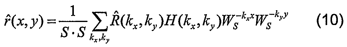
The phase-correlation function r(x,y) is the 2D inverse discrete Fourier transform (2D I DFT) of RQcx ,ky) :
r(x,y) kyWs-k*xWs-k>y (5)

If the two patterns
g(x,y) = e(s,i) (6)
and
g (x, y) = e(s + δ x , t + δ y ) (7)
are spatially sampled patterns of the same larger pattern e(s,f) at different positions, where ^and by are the displacements in x and y directions, respectively, and T is the spatial sampling interval, then the phase correlation function becomes:
r(x,y) = δ(x+δx,y+δy) (8)
δ(x+δx, y+δy) is the Kronecker delta function, which is one only at the position (δx,δy) and zero elsewhere. Therefore, the translation between two patterns can easily be measured by determining the position (δx,δy) of the Kronecker delta in the phase-correlation function.
In a preferred embodiment, determination of the displacement is extended to sub-pixel displacement measurement. In the present application, for typical patterns of extracted sections, most of the energy is concentrated typically in the low spatial frequency components. Therefore, a low-pass-type weighting function H{kx,ky) is applied to the cross-phase spectrum R(Jcx, ky) . In order to get a well-defined peak in the phase-correlation function, a Gaussian weighting is used:
H(kx,ky)
 (9)
where σ is a parameter that controls the function width. The phase- correlation function then becomes:
(9)
where σ is a parameter that controls the function width. The phase- correlation function then becomes:
which convolves the Kronecker delta function δ(x+δx,y + δy) with a Gaussian, resulting in:
which is again a Gaussian. In order to find the translated position (βx,δy) of this Gaussian peak with sub-pixel accuracy, a simplified model of the Gaussian is fitted to the phase-correlation result. The model is:
z(x,y) z a -e-[blχ-δ*)2+φ-δ>)2] -d (12)
where a, b, c, d, δx , and δy are the unknown model parameters.
Rearranging Equation (12), and, for simplicity, writing only z instead of z(x, y), we obtain:
Iog(z-d) = log(a)-b(x2 -2δxx + δx 2)-c(y2 -2δyy+δy 2) (13)
From this equation, the following linear system can be derived:

AC = Z (13)
and is solved as:
C = (A7Ay1Z (15)
From the first four elements of C, the sub-pixel translation (δx, δγ) can easily be determined. Since the phase correlation function has a very sharp peak, a limited number of data points (e.g. m*m = 3*3...9*9) around the maximum peak of rH(x,y) are enough to achieve a high-accuracy least squares function fitting.
The sub-pixel registration works best, when the displacement [δx, δγ] is small enough in comparison with the total image size w. This can be achieved, if a two-step coarse-to-fine approach is implemented, as illustrated in Figure 8. The reference section 5' is extracted with a size larger than the partial section 5 used for phase-correlation, e.g. two times the size (2w*2w) of comparative sections (w*w). In a first step S20, a w*w partial section 5, placed in a defined location in the reference section 5', is processed with a comparative section 6 (associated with an advanced instrument position) by phase correlation. However, the sub-pixel registration using the fit to a Gaussian surface is omitted, and only the position [Ax, Δy] of the pixel with the maximum value is used in order to get a first shift only with pixel accuracy. The defined location is, for example, the center of the reference section 5'. Alternatively, the defined location is determined from previous displacement measures, estimating an expected location of the comparative section. In a second step S21 , a new partial section 5" is extracted from the reference section 5', which is shifted by [Ax, Ay] from the center. Using this new partial section 5", and processing it with comparative section 6 (associated with the advanced instrument position) by
applying sub-pixel registration, the sub-pixel shift [δx, δγ] is computed. The total shift is then [Δx+δx, Δy+δγ], which is the displacement value resulting from the present iris pattern motion detection process.
In an embodiment, the measurement module 134 is further configured to determine in step S8 cyclotorsion or cyclorotation of the eye 3. Cyclotorsion or cyclorotation of the eye 3 is preferably determined from a set of multiple reference sections extracted in step S4 and from a set of multiple comparative sections extracted in step S7. For example, cyclotorsion or cyclorotation of the eye 3 is determined from the displacement between a first pair of corresponding reference and comparative sections and from the displacement between a second pair of corresponding reference and comparative sections. Alternatively, cyclotorsion or cyclorotation of the eye 3 is determined from the displacement between the reference section and the comparative section, and from a displacement determined between reflections in the initial top view image 3A, captured in step S3, and reflections in the top view image 3A, captured in step S6 at the current (advanced) instrument position.
In step S9, the control module 131 checks whether a full measurement cycle with all defined instruments positions has been processed (e.g. full rotation back to initial instrument position). If there are further instrument positions to be processed, the control module 131 continues in step S5 and moves the ophthalmological device 1 to next instrument position. Otherwise, if all instrument positions have been processed, the control module 131 continues in step S10.
In step S10, the positioning module 135 positions the cross-sectional image(s) 3OA, 3OB, captured in step S6 relative to the cross-sectional image(s)
3OA, 3OB, captured in step S3, based on the displacement, determined in step
S8. In essence the displacement is a measure for the movement of the eye relative to the ophthalmological device 1. The displacement determined from
top view images 3A is transformed into a translational and rotational displacement in three dimensional space based on geometrical parameters of the calibrated ophthalmological device 1. Thus, based on the knowledge of the respective instrument position and based on the (eye) displacement, the positioning module 135 positions relative to each other the cross-sectional image(s) 3OA, 3OB captured during an entire measurement cycle. The iris pattern motion detection and cross-sectional image alignment process ends in step S11.
One skilled in the art will understand that different sequences of steps S1- S11 are possible without deviating from the scope of the present invention. For example, step S7, or steps S7 and S8, can be processed after step S9, when all imaging data has been captured, e.g. after a full measurement cycle.
Using the composition module 136, the plurality of cross-sectional images 3OA, captured, stored, and positioned relative to one another are merged to a three-dimensional image of the anterior chamber structures of the eye 3, in particular of the cornea 30.
The measurement module 134 is further configured to determine eye structures in the captured and stored cross-sectional images 3OA, 3OB, in particular images of the cornea with the anterior corneal surface 31 A, 31 B and the posterior corneal surface 32A, 32B, and to determine distances, or respectively thicknesses, based thereon, in particular the measurement values DA and DB of the distances between the anterior corneal surface 31 A, 31 B and the posterior corneal surface 32A, 32B for determination of the corneal thickness D.
The electrical supply of the ophthalmologic device 1 takes place through an internal energy source or through an external energy source connected by means of cable.
The ophthalmological device 1 also comprises a display 14 on which determined measurement values and/or application aids are shown.
Claims
1. An ophthalmological device (1 ), comprising:
a light projector (11) configured to project a beam of rays (2) through a cross-sectional portion (4) of an eye (3);
first image-capturing means disposed in Scheimpflug configuration with respect to the beam of rays (2) and configured to capture in a first instrument position a cross-sectional image (3OA, 30B) of at least a sub- area of the cross-sectional portion (4), illuminated by the light projector (11);
a motion driver (15) configured to move the first image-capturing means to a second instrument position, at which second instrument position the first image-capturing means are disposed in Scheimpflug configuration with respect to the beam of rays (2);
second image-capturing means configured to capture a first top view image of at least part of the eye (3A), while capturing the cross-sectional image (3OA, 30B) in the first instrument position, and a second top view image (3A) of at least part of the eye, while capturing the cross-sectional image (3OA, 30B) in the second instrument position;
an extraction module (132) configured to extract at least one reference section (5) from the first top view image (3A), and at least one comparative section (6) from the second top view image (3A);
a measurement module (134) configured to determine a displacement between the reference section (5) and the comparative section (6); and a positioning module (135) configured to position relative to each other cross-sectional images (3OA, 30B), captured in the first instrument position and the second instrument position, based on the displacement.
2. The device (1) of claim 1 , wherein the extraction module (132) is configured to extract the at least one reference section (5) from an iris structure (34) in the first top view image (3A), and to extract the at least one comparative section (6) from the iris structure (34) in the second top view image (3A).
3. The device (1) of claim 2, wherein the extraction module (132) is configured to extract the reference and comparative sections (5,6) from an iris structure (34) that is essentially irremovable relative to the eye's eyeball.
4. The device (1) of one of claims 2 or 3, wherein the extraction module (132) is configured to extract the reference and comparative sections (5, 6) from an iris structure (34) that is essentially adjacent to the eye's limbus
(33).
5. The device (1) of one of claims 1 to 4, wherein the measurement module (134) is further configured to determine cyclotorsion and/or cyclorotation of the eye (3) from a combination of a first set of sections, comprising at least a first reference section and a corresponding first comparative section, and a second set of sections, comprising at least a second reference section and a corresponding second comparative section.
6. The device (1) of one of claims 1 to 5, wherein the second image- capturing means are further configured to capture with the first and second top view images (3A) reflections (36) on the eye (3); and wherein the measurement module (134) is further configured to determine cyclotorsion and/or cyclorotation of the eye (3) from the displacement between the reference section (5) and the comparative section (6), and from a displacement determined between reflections (36) in the first top view image (3A) and reflections (36) in the second top view image (3A).
7. The device (1) of one of claims 1 to 6, wherein the second image- capturing means are coupled with the motion driver (15) such that the first top view image (3A) is captured from a position linked with the first instrument position, and the second top view image (3A) is captured from a position linked with the second instrument position; and wherein the device (1) further comprises a compensator module (133) configured to determine the at least one comparative section (6) from the second top view image (3A), using a reverse transformation to compensate for movement of the second image-capturing means.
8. The device (1) of one of claims 1 to 7, wherein the measurement module (134) is configured to determine the displacement using a phase- correlation algorithm.
9. The device (1) of claim 8, wherein the measurement module (134) is configured to determine the displacement using sub-pixel phase- correlation.
10. The device (1) of one of claims 1 to 9, wherein the extraction module (132) is configured to extract the reference section (5') with an area larger than the area of the comparative section (6); wherein the measurement module (134) is configured to determine an initial displacement value (Δx, Δy) using a phase-correlation algorithm for the comparative section (6) and a partial reference section (5) having a defined location within the reference section (5'); and wherein the measurement module (134) is configured to determine the displacement using sub-pixel phase- correlation for the partial reference section (5") being moved off the defined location by the initial displacement value (Δx, Δy).
11. The device (1) of claim 10, wherein the measurement module (134) is configured to determine the defined location of the partial reference section (5) from one of previous displacement measures and the center of the reference section (5').
12. The device (1) of one of claims 1 to 11 , wherein the motion driver (15) is configured to rotate the light projector (11) and the first image-capturing means essentially about a normal to the surface of the eye (3), turned toward the light projector (11), or to shift them substantially perpendicular to this normal.
13. The device (1) of one of claims 1 to 12, wherein the extraction module (132) is configured to extract the reference and comparative sections (5, 6) as an array having equal number of rows and columns.
14. An ophthalmological measuring method, comprising:
projecting a beam of rays (2) through a cross-sectional portion (4) of an eye (3);
capturing in a first instrument position a cross-sectional image (3OA, 30B) of at least a sub-area of the cross-sectional portion (4), illuminated by the light projector (11), by first image-capturing means disposed in
Scheimpflug configuration with respect to the beam of rays (2);
moving the first image-capturing means to a second instrument position, at which second instrument position the first image-capturing means are disposed in Scheimpflug configuration with respect to the beam of rays (2); capturing, by second image-capturing means, a first top view image (3A) of at least part of the eye (3), while capturing the cross-sectional image (3OA, 30B) in the first instrument position, and a second top view image (3A) of at least part of the eye (3), while capturing the cross-sectional image (3OA, 30B) in the second instrument position;
extracting at least one reference section (5) from the first top view image (3A), and at least one comparative section (6) from the second top view image (3A);
determining a displacement between the reference section (5) and the comparative section (6); and
positioning relative to each other cross-sectional image (3OA, 30B)s, captured in the first instrument position and the second instrument position, based on the displacement.
15. The method of claim 14, wherein the at least one reference section (5) is extracted from an iris structure (34) in the first top view image (3A); and wherein the at least one comparative section (6) is extracted from the iris structure (34) in the second top view image (3A).
16. The method of claim 15, wherein the reference and comparative sections (5, 6) are extracted from an iris structure (34) that is essentially irremovable relative to the eye's eyeball.
17. The method of one of claims 15 or 16, wherein the reference and comparative sections (5, 6) are extracted from an iris structure (34) that is essentially adjacent to the eye's limbus (33).
18. The method of one of claims 14 to 17, further comprising determining cyclotorsion and(or cyclorotation of the eye (3) from a combination of a first set of sections, comprising at least a first reference section and a corresponding first comparative section, and a second set of sections, comprising at least a second reference section and a corresponding second comparative section.
19. The method of one of claims 14 to 18, further comprising capturing reflections (36) on the eye (3) with the first and second top view image (3A)s; determining a reflection displacement between reflections (36) in the first top view image (3A) and reflections (36) in the second top view image (3A); and determining cyclotorsion and/or cyclorotation of the eye (3) from the displacement, between the reference section (5) and the comparative section (6), and from the reflection displacement.
20. The method of one of claims 14 to 19, further comprising moving the second image-capturing means together with the first image-capturing means, such that the first top view image (3A) is captured from a position linked with the first instrument position, and the second top view image
(3A) is captured from a position linked with the second instrument position; and determining the at least one comparative section (6) from the second top view image (3A), using a reverse transformation to compensate for movement of the second image-capturing means.
21. The method of one of claims 14 to 20, wherein the displacement is determined using a phase-correlation algorithm.
22. The method of claim 21 , wherein the displacement is determined using sub-pixel phase-correlation.
23. The method of one of claims 14 to 22, wherein the reference section (5') is extracted with an area larger than the area of the comparative section
(6); wherein an initial displacement value (Δx, Δy) is determined using a phase-correlation algorithm for the comparative section (6) and a partial reference section (5) having a defined location within the reference section (5'); and wherein the displacement is determined using sub-pixel phase-correlation for the partial reference section (5") being moved off the defined location by the initial displacement value (ΔX1 Δy).
24. The method of claim 23, wherein the defined location of the partial reference section (5) is determined from one of previous displacement measures and the center of the reference section (5').
25. The method of one of claims 14 to 24, wherein the light projector (11 ) and the first image-capturing means are rotated essentially about a normal to the surface of the eye (3) turned towards the light projector (11 ), or shifted substantially perpendicular to this normal.
26. The method of one of claims 14 to 25, wherein the reference and comparative sections (5, 6) are extracted as an array having equal number of rows and columns.
Priority Applications (5)
| Application Number | Priority Date | Filing Date | Title |
|---|---|---|---|
| PCT/CH2006/000153 WO2007104166A1 (en) | 2006-03-16 | 2006-03-16 | Ophthalmological device and ophthalmological measuring method |
| DE602006017895T DE602006017895D1 (en) | 2006-03-16 | 2006-03-16 | OPHTHALMOLOGICAL DEVICE AND OPHTHALMOLOGICAL MEASUREMENT METHOD |
| AT06705393T ATE485758T1 (en) | 2006-03-16 | 2006-03-16 | OPHTHALMOLOGICAL DEVICE AND OPHTHALMOLOGICAL MEASURING METHOD |
| EP06705393A EP1998662B1 (en) | 2006-03-16 | 2006-03-16 | Ophthalmological device and ophthalmological measuring method |
| US12/282,575 US7959289B2 (en) | 2006-03-16 | 2006-03-16 | Ophthalmological device and ophthalmological measuring method |
Applications Claiming Priority (1)
| Application Number | Priority Date | Filing Date | Title |
|---|---|---|---|
| PCT/CH2006/000153 WO2007104166A1 (en) | 2006-03-16 | 2006-03-16 | Ophthalmological device and ophthalmological measuring method |
Publications (1)
| Publication Number | Publication Date |
|---|---|
| WO2007104166A1 true WO2007104166A1 (en) | 2007-09-20 |
Family
ID=37388804
Family Applications (1)
| Application Number | Title | Priority Date | Filing Date |
|---|---|---|---|
| PCT/CH2006/000153 Ceased WO2007104166A1 (en) | 2006-03-16 | 2006-03-16 | Ophthalmological device and ophthalmological measuring method |
Country Status (5)
| Country | Link |
|---|---|
| US (1) | US7959289B2 (en) |
| EP (1) | EP1998662B1 (en) |
| AT (1) | ATE485758T1 (en) |
| DE (1) | DE602006017895D1 (en) |
| WO (1) | WO2007104166A1 (en) |
Cited By (6)
| Publication number | Priority date | Publication date | Assignee | Title |
|---|---|---|---|---|
| WO2010010203A1 (en) * | 2008-07-24 | 2010-01-28 | Universidad Complutense De Madrid | Biometric recognition through examination of the surface map of the second ocular dioptric |
| WO2012134986A1 (en) | 2011-03-25 | 2012-10-04 | Lensar, Inc. | System and method for measuring tilt in the crystalline lens for laser phaco fragmentation |
| CN103799973A (en) * | 2012-11-09 | 2014-05-21 | 佳能株式会社 | Ophthalmic apparatus and alignment determination method |
| RU2604711C1 (en) * | 2015-08-17 | 2016-12-10 | Игорь Михайлович Корниловский | Method for assessing tolerance of medications during epibulbar use thereof |
| US10772499B2 (en) | 2009-07-25 | 2020-09-15 | Lensar, Inc. | System and method for measuring tilt |
| US11992266B2 (en) | 2008-07-25 | 2024-05-28 | Lensar, Inc. | System and method for measuring tilt in the crystalline lens for laser phaco fragmentation |
Families Citing this family (26)
| Publication number | Priority date | Publication date | Assignee | Title |
|---|---|---|---|---|
| US9545338B2 (en) | 2006-01-20 | 2017-01-17 | Lensar, Llc. | System and method for improving the accommodative amplitude and increasing the refractive power of the human lens with a laser |
| US9889043B2 (en) | 2006-01-20 | 2018-02-13 | Lensar, Inc. | System and apparatus for delivering a laser beam to the lens of an eye |
| US10842675B2 (en) | 2006-01-20 | 2020-11-24 | Lensar, Inc. | System and method for treating the structure of the human lens with a laser |
| US9168173B2 (en) | 2008-04-04 | 2015-10-27 | Truevision Systems, Inc. | Apparatus and methods for performing enhanced visually directed procedures under low ambient light conditions |
| US8480659B2 (en) | 2008-07-25 | 2013-07-09 | Lensar, Inc. | Method and system for removal and replacement of lens material from the lens of an eye |
| US8500723B2 (en) | 2008-07-25 | 2013-08-06 | Lensar, Inc. | Liquid filled index matching device for ophthalmic laser procedures |
| US9226798B2 (en) | 2008-10-10 | 2016-01-05 | Truevision Systems, Inc. | Real-time surgical reference indicium apparatus and methods for surgical applications |
| US10117721B2 (en) | 2008-10-10 | 2018-11-06 | Truevision Systems, Inc. | Real-time surgical reference guides and methods for surgical applications |
| US8768014B2 (en) * | 2009-01-14 | 2014-07-01 | Indiana University Research And Technology Corp. | System and method for identifying a person with reference to a sclera image |
| US9173717B2 (en) | 2009-02-20 | 2015-11-03 | Truevision Systems, Inc. | Real-time surgical reference indicium apparatus and methods for intraocular lens implantation |
| JP2013500086A (en) | 2009-07-24 | 2013-01-07 | レンサー, インク. | System and method for performing a procedure using LADAR on an eye lens |
| EP2456384B1 (en) | 2009-07-24 | 2023-09-20 | LENSAR, Inc. | System for providing laser shot patterns to the lens of an eye |
| US8617146B2 (en) | 2009-07-24 | 2013-12-31 | Lensar, Inc. | Laser system and method for correction of induced astigmatism |
| US8758332B2 (en) | 2009-07-24 | 2014-06-24 | Lensar, Inc. | Laser system and method for performing and sealing corneal incisions in the eye |
| US8556425B2 (en) | 2010-02-01 | 2013-10-15 | Lensar, Inc. | Purkinjie image-based alignment of suction ring in ophthalmic applications |
| CN106974614B (en) | 2010-10-15 | 2019-04-26 | 雷萨公司 | System and method for scan-controlled illumination of structures inside the eye |
| USD695408S1 (en) | 2010-10-15 | 2013-12-10 | Lensar, Inc. | Laser system for treatment of the eye |
| USD694890S1 (en) | 2010-10-15 | 2013-12-03 | Lensar, Inc. | Laser system for treatment of the eye |
| ES3010062T3 (en) * | 2011-03-25 | 2025-04-01 | Lensar Inc | System for measuring and correcting astigmatism using laser generated corneal incisions |
| US10463541B2 (en) | 2011-03-25 | 2019-11-05 | Lensar, Inc. | System and method for correcting astigmatism using multiple paired arcuate laser generated corneal incisions |
| US9039176B2 (en) * | 2011-03-31 | 2015-05-26 | Nidek Co., Ltd. | Corneal endothelial cell photographing apparatus |
| WO2014036499A1 (en) | 2012-08-30 | 2014-03-06 | Truevision Systems, Inc. | Imaging system and methods displaying a fused multidimensional reconstructed image |
| US11083537B2 (en) | 2017-04-24 | 2021-08-10 | Alcon Inc. | Stereoscopic camera with fluorescence visualization |
| US10299880B2 (en) | 2017-04-24 | 2019-05-28 | Truevision Systems, Inc. | Stereoscopic visualization camera and platform |
| US10917543B2 (en) | 2017-04-24 | 2021-02-09 | Alcon Inc. | Stereoscopic visualization camera and integrated robotics platform |
| JP7321678B2 (en) * | 2018-06-13 | 2023-08-07 | 株式会社トプコン | slit lamp microscope and ophthalmic system |
Citations (1)
| Publication number | Priority date | Publication date | Assignee | Title |
|---|---|---|---|---|
| EP1430829A1 (en) * | 2002-12-16 | 2004-06-23 | SIS AG Surgical Instrument Systems | Ophthalmic device and measuring method |
Family Cites Families (2)
| Publication number | Priority date | Publication date | Assignee | Title |
|---|---|---|---|---|
| US5094521A (en) * | 1990-11-07 | 1992-03-10 | Vision Research Laboratories | Apparatus for evaluating eye alignment |
| EP1602321A1 (en) * | 2004-06-02 | 2005-12-07 | SensoMotoric Instruments GmbH | Method and apparatus for image-based eye tracking for retinal diagnostic or surgery device |
-
2006
- 2006-03-16 EP EP06705393A patent/EP1998662B1/en not_active Expired - Lifetime
- 2006-03-16 DE DE602006017895T patent/DE602006017895D1/en not_active Expired - Lifetime
- 2006-03-16 US US12/282,575 patent/US7959289B2/en active Active
- 2006-03-16 WO PCT/CH2006/000153 patent/WO2007104166A1/en not_active Ceased
- 2006-03-16 AT AT06705393T patent/ATE485758T1/en not_active IP Right Cessation
Patent Citations (1)
| Publication number | Priority date | Publication date | Assignee | Title |
|---|---|---|---|---|
| EP1430829A1 (en) * | 2002-12-16 | 2004-06-23 | SIS AG Surgical Instrument Systems | Ophthalmic device and measuring method |
Cited By (12)
| Publication number | Priority date | Publication date | Assignee | Title |
|---|---|---|---|---|
| WO2010010203A1 (en) * | 2008-07-24 | 2010-01-28 | Universidad Complutense De Madrid | Biometric recognition through examination of the surface map of the second ocular dioptric |
| ES2337866A1 (en) * | 2008-07-24 | 2010-04-29 | Universidad Complutense De Madrid | BIOMETRIC RECOGNITION THROUGH STUDY OF THE SURFACE MAP OF THE SECOND OCULAR DIOPTRY. |
| ES2337866B2 (en) * | 2008-07-24 | 2011-02-14 | Universidad Complutense De Madrid | BIOMETRIC RECOGNITION THROUGH STUDY OF THE SURFACE MAP OF THE SECOND OCULAR DIOPTRY. |
| CN102131454A (en) * | 2008-07-24 | 2011-07-20 | 马德里康普拉坦斯大学 | Biometric identification by examining the surface map of the second eye refraction |
| US11185226B2 (en) | 2008-07-25 | 2021-11-30 | Lensar, Inc. | System and method for measuring tilt in the crystalline lens for laser phaco fragmentation |
| US11992266B2 (en) | 2008-07-25 | 2024-05-28 | Lensar, Inc. | System and method for measuring tilt in the crystalline lens for laser phaco fragmentation |
| US10772499B2 (en) | 2009-07-25 | 2020-09-15 | Lensar, Inc. | System and method for measuring tilt |
| WO2012134986A1 (en) | 2011-03-25 | 2012-10-04 | Lensar, Inc. | System and method for measuring tilt in the crystalline lens for laser phaco fragmentation |
| EP2688504A4 (en) * | 2011-03-25 | 2015-08-26 | Lensar Inc | SYSTEM AND METHOD FOR MEASURING CURVATURE IN CRYSTALLINE FOR LASER PHACO-FRAGMENTATION |
| EP4169465A1 (en) * | 2011-03-25 | 2023-04-26 | Lensar, Inc. | System for measuring tilt in the crystalline lens for laser phaco fragmentation |
| CN103799973A (en) * | 2012-11-09 | 2014-05-21 | 佳能株式会社 | Ophthalmic apparatus and alignment determination method |
| RU2604711C1 (en) * | 2015-08-17 | 2016-12-10 | Игорь Михайлович Корниловский | Method for assessing tolerance of medications during epibulbar use thereof |
Also Published As
| Publication number | Publication date |
|---|---|
| US20090303437A1 (en) | 2009-12-10 |
| DE602006017895D1 (en) | 2010-12-09 |
| US7959289B2 (en) | 2011-06-14 |
| EP1998662A1 (en) | 2008-12-10 |
| ATE485758T1 (en) | 2010-11-15 |
| EP1998662B1 (en) | 2010-10-27 |
Similar Documents
| Publication | Publication Date | Title |
|---|---|---|
| EP1998662B1 (en) | Ophthalmological device and ophthalmological measuring method | |
| JP7404534B2 (en) | Surgical applications using integrated visualization camera and optical coherence tomography | |
| US7480396B2 (en) | Multidimensional eye tracking and position measurement system for diagnosis and treatment of the eye | |
| US7264355B2 (en) | Ophthalmologic device and ophthalmologic measuring method | |
| KR101772857B1 (en) | Apparatus for optical coherence tomography of an eye and method for optical coherence tomography of an eye | |
| CA2487411C (en) | Tracking torsional eye orientation and position | |
| JP4515687B2 (en) | Eye registration and astigmatism alignment control system and method | |
| EP1480550B1 (en) | Determining relative positional and rotational offsets | |
| JP6184232B2 (en) | Image processing apparatus and image processing method | |
| CA2818252A1 (en) | Scanning and processing using optical coherence tomography | |
| US10803634B2 (en) | Reconstruction of three dimensional model of an object compensating for object orientation changes between surface or slice scans | |
| CA2388719A1 (en) | Rapid, automatic measurement of the eye's wave aberraion | |
| US20020154269A1 (en) | Stereoscopic measurement of cornea and illumination patterns | |
| CN105011900A (en) | Method and device for generating a wide-field optical coherence tomography (OCT) image | |
| WO2009140086A2 (en) | Method for optically scanning objects | |
| Lee et al. | Objective and expert-independent validation of retinal image registration algorithms by a projective imaging distortion model | |
| EP3459434B1 (en) | Ophthalmologic apparatus and method of controlling the same | |
| JP7650890B2 (en) | Method and apparatus for orbit determination and imaging - Patents.com | |
| US20100111381A1 (en) | Methods and Apparatus for Facilitating Elimination of Ambient Light from an Image | |
| Oliveira et al. | Imaging of aphakic intraocular lens with a slit-scanning tomography system | |
| Greenwood | Computerised stereoscopic measurement of the human retina | |
| Shokouhi et al. | Cost-effective system for facial imaging and three-dimensional reconstruction |
Legal Events
| Date | Code | Title | Description |
|---|---|---|---|
| 121 | Ep: the epo has been informed by wipo that ep was designated in this application | ||
| WWE | Wipo information: entry into national phase |
Ref document number: 2006705393 Country of ref document: EP |
|
| NENP | Non-entry into the national phase |
Ref country code: DE |
|
| WWE | Wipo information: entry into national phase |
Ref document number: 12282575 Country of ref document: US |