WO2007132694A1 - 粘着シートおよび玉型加工方法 - Google Patents
粘着シートおよび玉型加工方法 Download PDFInfo
- Publication number
- WO2007132694A1 WO2007132694A1 PCT/JP2007/059470 JP2007059470W WO2007132694A1 WO 2007132694 A1 WO2007132694 A1 WO 2007132694A1 JP 2007059470 W JP2007059470 W JP 2007059470W WO 2007132694 A1 WO2007132694 A1 WO 2007132694A1
- Authority
- WO
- WIPO (PCT)
- Prior art keywords
- lens
- sensitive adhesive
- adhesive sheet
- pressure
- layer
- Prior art date
- Legal status (The legal status is an assumption and is not a legal conclusion. Google has not performed a legal analysis and makes no representation as to the accuracy of the status listed.)
- Ceased
Links
Classifications
-
- B—PERFORMING OPERATIONS; TRANSPORTING
- B24—GRINDING; POLISHING
- B24B—MACHINES, DEVICES, OR PROCESSES FOR GRINDING OR POLISHING; DRESSING OR CONDITIONING OF ABRADING SURFACES; FEEDING OF GRINDING, POLISHING, OR LAPPING AGENTS
- B24B9/00—Machines or devices designed for grinding edges or bevels on work or for removing burrs; Accessories therefor
- B24B9/02—Machines or devices designed for grinding edges or bevels on work or for removing burrs; Accessories therefor characterised by a special design with respect to properties of materials specific to articles to be ground
- B24B9/06—Machines or devices designed for grinding edges or bevels on work or for removing burrs; Accessories therefor characterised by a special design with respect to properties of materials specific to articles to be ground of non-metallic inorganic material, e.g. stone, ceramics, porcelain
- B24B9/08—Machines or devices designed for grinding edges or bevels on work or for removing burrs; Accessories therefor characterised by a special design with respect to properties of materials specific to articles to be ground of non-metallic inorganic material, e.g. stone, ceramics, porcelain of glass
- B24B9/14—Machines or devices designed for grinding edges or bevels on work or for removing burrs; Accessories therefor characterised by a special design with respect to properties of materials specific to articles to be ground of non-metallic inorganic material, e.g. stone, ceramics, porcelain of glass of optical work, e.g. lenses, prisms
-
- B—PERFORMING OPERATIONS; TRANSPORTING
- B24—GRINDING; POLISHING
- B24B—MACHINES, DEVICES, OR PROCESSES FOR GRINDING OR POLISHING; DRESSING OR CONDITIONING OF ABRADING SURFACES; FEEDING OF GRINDING, POLISHING, OR LAPPING AGENTS
- B24B13/00—Machines or devices designed for grinding or polishing optical surfaces on lenses or surfaces of similar shape on other work; Accessories therefor
- B24B13/005—Blocking means, chucks or the like; Alignment devices
-
- B—PERFORMING OPERATIONS; TRANSPORTING
- B24—GRINDING; POLISHING
- B24B—MACHINES, DEVICES, OR PROCESSES FOR GRINDING OR POLISHING; DRESSING OR CONDITIONING OF ABRADING SURFACES; FEEDING OF GRINDING, POLISHING, OR LAPPING AGENTS
- B24B9/00—Machines or devices designed for grinding edges or bevels on work or for removing burrs; Accessories therefor
- B24B9/02—Machines or devices designed for grinding edges or bevels on work or for removing burrs; Accessories therefor characterised by a special design with respect to properties of materials specific to articles to be ground
- B24B9/06—Machines or devices designed for grinding edges or bevels on work or for removing burrs; Accessories therefor characterised by a special design with respect to properties of materials specific to articles to be ground of non-metallic inorganic material, e.g. stone, ceramics, porcelain
- B24B9/08—Machines or devices designed for grinding edges or bevels on work or for removing burrs; Accessories therefor characterised by a special design with respect to properties of materials specific to articles to be ground of non-metallic inorganic material, e.g. stone, ceramics, porcelain of glass
- B24B9/14—Machines or devices designed for grinding edges or bevels on work or for removing burrs; Accessories therefor characterised by a special design with respect to properties of materials specific to articles to be ground of non-metallic inorganic material, e.g. stone, ceramics, porcelain of glass of optical work, e.g. lenses, prisms
- B24B9/146—Accessories, e.g. lens mounting devices
-
- B—PERFORMING OPERATIONS; TRANSPORTING
- B32—LAYERED PRODUCTS
- B32B—LAYERED PRODUCTS, i.e. PRODUCTS BUILT-UP OF STRATA OF FLAT OR NON-FLAT, e.g. CELLULAR OR HONEYCOMB, FORM
- B32B27/00—Layered products comprising a layer of synthetic resin
- B32B27/06—Layered products comprising a layer of synthetic resin as the main or only constituent of a layer, which is next to another layer of the same or of a different material
- B32B27/065—Layered products comprising a layer of synthetic resin as the main or only constituent of a layer, which is next to another layer of the same or of a different material of foam
-
- B—PERFORMING OPERATIONS; TRANSPORTING
- B32—LAYERED PRODUCTS
- B32B—LAYERED PRODUCTS, i.e. PRODUCTS BUILT-UP OF STRATA OF FLAT OR NON-FLAT, e.g. CELLULAR OR HONEYCOMB, FORM
- B32B27/00—Layered products comprising a layer of synthetic resin
- B32B27/32—Layered products comprising a layer of synthetic resin comprising polyolefins
-
- C—CHEMISTRY; METALLURGY
- C09—DYES; PAINTS; POLISHES; NATURAL RESINS; ADHESIVES; COMPOSITIONS NOT OTHERWISE PROVIDED FOR; APPLICATIONS OF MATERIALS NOT OTHERWISE PROVIDED FOR
- C09J—ADHESIVES; NON-MECHANICAL ASPECTS OF ADHESIVE PROCESSES IN GENERAL; ADHESIVE PROCESSES NOT PROVIDED FOR ELSEWHERE; USE OF MATERIALS AS ADHESIVES
- C09J7/00—Adhesives in the form of films or foils
- C09J7/20—Adhesives in the form of films or foils characterised by their carriers
- C09J7/29—Laminated material
-
- C—CHEMISTRY; METALLURGY
- C09—DYES; PAINTS; POLISHES; NATURAL RESINS; ADHESIVES; COMPOSITIONS NOT OTHERWISE PROVIDED FOR; APPLICATIONS OF MATERIALS NOT OTHERWISE PROVIDED FOR
- C09J—ADHESIVES; NON-MECHANICAL ASPECTS OF ADHESIVE PROCESSES IN GENERAL; ADHESIVE PROCESSES NOT PROVIDED FOR ELSEWHERE; USE OF MATERIALS AS ADHESIVES
- C09J7/00—Adhesives in the form of films or foils
- C09J7/30—Adhesives in the form of films or foils characterised by the adhesive composition
- C09J7/38—Pressure-sensitive adhesives [PSA]
- C09J7/381—Pressure-sensitive adhesives [PSA] based on macromolecular compounds obtained by reactions involving only carbon-to-carbon unsaturated bonds
- C09J7/385—Acrylic polymers
-
- B—PERFORMING OPERATIONS; TRANSPORTING
- B32—LAYERED PRODUCTS
- B32B—LAYERED PRODUCTS, i.e. PRODUCTS BUILT-UP OF STRATA OF FLAT OR NON-FLAT, e.g. CELLULAR OR HONEYCOMB, FORM
- B32B2266/00—Composition of foam
- B32B2266/02—Organic
- B32B2266/0214—Materials belonging to B32B27/00
- B32B2266/0278—Polyurethane
-
- B—PERFORMING OPERATIONS; TRANSPORTING
- B32—LAYERED PRODUCTS
- B32B—LAYERED PRODUCTS, i.e. PRODUCTS BUILT-UP OF STRATA OF FLAT OR NON-FLAT, e.g. CELLULAR OR HONEYCOMB, FORM
- B32B2405/00—Adhesive articles, e.g. adhesive tapes
-
- B—PERFORMING OPERATIONS; TRANSPORTING
- B32—LAYERED PRODUCTS
- B32B—LAYERED PRODUCTS, i.e. PRODUCTS BUILT-UP OF STRATA OF FLAT OR NON-FLAT, e.g. CELLULAR OR HONEYCOMB, FORM
- B32B2551/00—Optical elements
-
- C—CHEMISTRY; METALLURGY
- C09—DYES; PAINTS; POLISHES; NATURAL RESINS; ADHESIVES; COMPOSITIONS NOT OTHERWISE PROVIDED FOR; APPLICATIONS OF MATERIALS NOT OTHERWISE PROVIDED FOR
- C09J—ADHESIVES; NON-MECHANICAL ASPECTS OF ADHESIVE PROCESSES IN GENERAL; ADHESIVE PROCESSES NOT PROVIDED FOR ELSEWHERE; USE OF MATERIALS AS ADHESIVES
- C09J2400/00—Presence of inorganic and organic materials
- C09J2400/20—Presence of organic materials
- C09J2400/24—Presence of a foam
- C09J2400/243—Presence of a foam in the substrate
-
- C—CHEMISTRY; METALLURGY
- C09—DYES; PAINTS; POLISHES; NATURAL RESINS; ADHESIVES; COMPOSITIONS NOT OTHERWISE PROVIDED FOR; APPLICATIONS OF MATERIALS NOT OTHERWISE PROVIDED FOR
- C09J—ADHESIVES; NON-MECHANICAL ASPECTS OF ADHESIVE PROCESSES IN GENERAL; ADHESIVE PROCESSES NOT PROVIDED FOR ELSEWHERE; USE OF MATERIALS AS ADHESIVES
- C09J2433/00—Presence of (meth)acrylic polymer
-
- Y—GENERAL TAGGING OF NEW TECHNOLOGICAL DEVELOPMENTS; GENERAL TAGGING OF CROSS-SECTIONAL TECHNOLOGIES SPANNING OVER SEVERAL SECTIONS OF THE IPC; TECHNICAL SUBJECTS COVERED BY FORMER USPC CROSS-REFERENCE ART COLLECTIONS [XRACs] AND DIGESTS
- Y10—TECHNICAL SUBJECTS COVERED BY FORMER USPC
- Y10T—TECHNICAL SUBJECTS COVERED BY FORMER US CLASSIFICATION
- Y10T428/00—Stock material or miscellaneous articles
- Y10T428/24—Structurally defined web or sheet [e.g., overall dimension, etc.]
- Y10T428/24273—Structurally defined web or sheet [e.g., overall dimension, etc.] including aperture
- Y10T428/24322—Composite web or sheet
-
- Y—GENERAL TAGGING OF NEW TECHNOLOGICAL DEVELOPMENTS; GENERAL TAGGING OF CROSS-SECTIONAL TECHNOLOGIES SPANNING OVER SEVERAL SECTIONS OF THE IPC; TECHNICAL SUBJECTS COVERED BY FORMER USPC CROSS-REFERENCE ART COLLECTIONS [XRACs] AND DIGESTS
- Y10—TECHNICAL SUBJECTS COVERED BY FORMER USPC
- Y10T—TECHNICAL SUBJECTS COVERED BY FORMER US CLASSIFICATION
- Y10T428/00—Stock material or miscellaneous articles
- Y10T428/28—Web or sheet containing structurally defined element or component and having an adhesive outermost layer
- Y10T428/2848—Three or more layers
-
- Y—GENERAL TAGGING OF NEW TECHNOLOGICAL DEVELOPMENTS; GENERAL TAGGING OF CROSS-SECTIONAL TECHNOLOGIES SPANNING OVER SEVERAL SECTIONS OF THE IPC; TECHNICAL SUBJECTS COVERED BY FORMER USPC CROSS-REFERENCE ART COLLECTIONS [XRACs] AND DIGESTS
- Y10—TECHNICAL SUBJECTS COVERED BY FORMER USPC
- Y10T—TECHNICAL SUBJECTS COVERED BY FORMER US CLASSIFICATION
- Y10T428/00—Stock material or miscellaneous articles
- Y10T428/28—Web or sheet containing structurally defined element or component and having an adhesive outermost layer
- Y10T428/2852—Adhesive compositions
Definitions
- the present invention relates to an adhesive sheet disposed between at least one of a pair of chucks and a lens of a lens cutter, and a lens processing method using the adhesive sheet.
- an antireflection layer is formed on the surface of a spectacle lens in order to suppress light reflection and increase light transmittance.
- dirt, fingerprints, sweat, cosmetics, etc. often adhere to the antireflection layer, and stains tend to be noticeable. Also, it is difficult to remove the dirt.
- an antifouling layer is often provided by further antifouling treatment on the surface of the antireflection layer. In addition, this antifouling layer makes it easier to wipe off dirt, thereby preventing scratches (for example, Patent Document 1).
- the spectacle lens described in this publication, in which the antifouling layer is formed using the fluorine-containing silane compound has good antifouling properties and scratch resistance, and its effects are durable.
- Patent Document 2 JP-A-9 258003
- Patent Document 2 Japanese Patent Laid-Open No. 2004-249454
- An object of the present invention is to provide a pressure-sensitive adhesive sheet and a lens shape processing method in which axial misalignment hardly occurs.
- the pressure-sensitive adhesive sheet of the present invention is a pressure-sensitive adhesive sheet disposed between at least one of a pair of chucks of a lens cutter and a lens, and a pressure-sensitive adhesive layer is formed at least on a portion facing the lens surface.
- the pressure-sensitive adhesive layer is a pressure-sensitive adhesive composition containing a polymer having (meth) acrylic acid ester as a main component, an adhesion-imparting resin, and a crosslinking agent.
- an adhesive sheet is disposed between the chuck and the lens in order to fix the lens to the chuck of the lens type cutter, and the lens and the chuck are brought into close contact with each other.
- the pressure-sensitive adhesive sheet used in the present invention has a pressure-sensitive adhesive layer made of a pressure-sensitive adhesive composition containing a polymer mainly composed of (meth) acrylic acid ester, a tackifier resin, and a crosslinking agent. Due to its excellent adhesiveness, the surface treatment with a fluorine-containing silane compound or the like has a small friction coefficient, and can exhibit an effect of preventing high-axis misalignment even for lenses.
- the mechanism that exhibits a high effect of preventing shaft misalignment is not clear, but it is considered as follows.
- the tackifier resin is added to a polymer mainly composed of (meth) acrylic acid ester having a high cohesive force, so that a tackifier resin which is a relatively hard component is added. Slightly bleed to attract fine irregularities The force is greatly increased and the shaft misalignment prevention performance is improved.
- the pressure-sensitive adhesive sheet has a base material layer formed adjacent to the pressure-sensitive adhesive layer.
- the base material layer is laminated on the sheet member and has one surface while being laminated on the sheet member.
- a film member provided with the adhesive layer.
- the sheet member is prevented from being excessively deformed in the direction perpendicular to the axial direction of the clamp of the target lens processing machine. Lens misalignment during processing can be prevented.
- a coating layer is provided on both the lens surface side and the lens surface side opposite to the lens surface of the base material layer, and at least the lens surface side of these coating layers is the pressure-sensitive adhesive layer. I like it.
- the coating layer disposed at least on the lens surface side is the adhesive layer having the above-described configuration, the force of pulling the fine irregularities on the lens surface of this adhesive layer can be used. Axis misalignment can be effectively prevented.
- the tackifier resin is terpene resin, ⁇ -pinene, terpene phenol copolymer, rosin and rosin derivatives, coumarone indene resin, hydrocarbon resin, alkylphenol resin, xylene resin, aromatic A composition consisting of one kind or a mixture of several kinds selected from petroleum resins is preferred.
- the pressure-sensitive adhesive layer has an internal haze force Sl% of 20 m in thickness by adding a tackifying resin that is incompatible with the polymer to a polymer mainly composed of (meth) acrylic acid ester.
- a tackifying resin that is incompatible with the polymer to a polymer mainly composed of (meth) acrylic acid ester.
- the above configuration is preferable.
- the pressure-sensitive adhesive layer has a thickness of 20 ⁇ m by adding a tackifying resin compatible with the polymer to at least 3 parts by weight with respect to 100 parts by weight of the polymer mainly composed of (meth) acrylic acid ester.
- the internal haze of the pressure-sensitive adhesive layer is preferably 1% or more.
- the sheet member has a configuration having elasticity capable of being compressed by 10% or more in a direction intersecting the lens surface.
- “has elasticity that can be compressed by 10% or more in the direction intersecting the lens surface” means that the adhesive sheet is formed when the adhesive sheet is sandwiched and pressed between the lens and the chuck of the lens processing machine.
- the thickness of the sheet member to be compressed is 10% or more (the thickness of the compressed sheet member is 90% of the original thickness). % Or less) means it can be compressed.
- the thickness of the sheet member before compression is preferably 0.5 mm or more.
- the sheet member of the base material layer has elasticity that can be compressed by 10% or more in the direction intersecting the lens surface, even if the lens surface is convex or concave, depending on its shape Thus, the adhesive sheet can be deformed.
- a lens clamping force is used to clamp the lens with a pair of chucks.
- a lens lock tape is unnecessary, and the lens can be firmly fixed with only one type of the adhesive sheet of the present invention.
- the lens does not lose its chucking force during mold molding!
- the process of the lens shape check is simplified, and the lens shape processing of the lens at the spectacle store or the like can be stably performed.
- the pressure-sensitive adhesive sheet of the present invention preferably has a configuration in which the sheet member is formed of a resin foam.
- the sheet member of the base material layer When the sheet member of the base material layer is formed from a resin foam, the sheet member easily compresses and deforms when pressed with the adhesive sheet sandwiched between the lens and the chuck.
- the adhesive sheet surface is easily deformed, the adhesive area between the adhesive sheet and the lens surface is increased, and the adhesive force is improved. That is, the adhesive strength of the adhesive sheet can be fully exhibited.
- the resin foam may be open-celled or closed-celled, but a type having closed-cells is preferable from the viewpoint of utilizing aeroelasticity.
- the foaming of resin can be either chemical foaming with a chemical foaming agent or physical foaming using a volatile solvent!
- the pressure-sensitive adhesive sheet of the present invention preferably has a configuration having an area larger than the contact area of the chuck.
- the adhesive sheet has an area equal to or larger than the contact area with the chuck, the chuck and the lens can be sufficiently adhered to each other, and even in the lens shape calorie. Can be fixed stably.
- the pressure-sensitive adhesive sheet is formed with a notch that allows a marking point attached to the lens to be visually recognized.
- the mark point is a so-called alignment marker that serves as a horizontal reference when the lens is cast. It is
- the pressure-sensitive adhesive sheet is formed with a notch for allowing the mark on the lens surface to be seen.
- the pressure-sensitive adhesive sheet itself includes a foam layer and is opaque
- an adhesive sheet can be affixed to the lens surface so as not to obscure the markings on the lens surface.
- the pressure-sensitive adhesive sheet has a hole formed so that a center point attached to the lens is visible.
- the adhesive sheet is formed with a hole for viewing the center point (marking point) attached to the lens surface.
- the adhesive sheet itself includes the foam layer. Even if it is opaque, the adhesive sheet can be attached to the lens surface so that the center point on the lens surface is not hidden.
- the marked fitting point mark can be avoided, and the mark disappears when the adhesive sheet is peeled off after the target lens has been processed. Can be prevented.
- the target lens processing method of the present invention is characterized by using the pressure-sensitive adhesive sheet having the above-described configuration.
- the lens axial displacement does not occur when the anti-fouling lens is subjected to the target lens cast, and the target lens force check process is simplified. Is done.
- a configuration in which a lens to be lens-shaped has at least a convex surface and an adhesive sheet is pasted on at least the convex surface of the lens is preferable.
- the pressure-sensitive adhesive sheet attached to the convex surface of the lens is more resistant to wrinkling than the pressure-sensitive adhesive sheet attached to the concave surface, and thus can exhibit stable adhesive force.
- FIG. 1 is a view showing a pressure-sensitive adhesive sheet that can be applied to the first embodiment of the present invention.
- FIG. 2 is a diagram showing a usage state of the pressure-sensitive adhesive sheet of the first embodiment.
- FIG. 3A is a plan view of a spectacle lens applied to a second embodiment of the present invention.
- FIG. 3B is a cross-sectional view of a spectacle lens applied to the second embodiment.
- FIG. 4 is a schematic cross-sectional view of a spectacle lens fixing portion that works according to a second embodiment.
- FIG. 5 is an exploded schematic view of a spectacle lens fixing portion that works according to the second embodiment.
- FIG. 6 is a schematic cross-sectional view of a spectacle lens fixing portion that works on a modification of the present invention.
- second cover layer (chuck-side adhesive layer), 510 ... lens holding member, 511 ... mounting portion, 511 ⁇ ... projection, 512 ... lens holding portion, 512 ⁇ ⁇ Lens holding surface, L... Spectacle lens, L 1... Convex surface, L2—Concave surface
- a first embodiment of the present invention will be described with reference to Figs.
- the first embodiment is an example applied to a spectacle lens.
- FIG. 1 is a diagram showing the configuration of the pressure-sensitive adhesive sheet that works on the first embodiment.
- reference numeral 1 denotes a spectacle lens
- reference numeral 2 denotes a spectacle lens fixing adhesive sheet provided on the spectacle lens 1.
- the adhesive sheet 2 for fixing the spectacle lens includes a base material layer 2a, a first covering layer 2bl provided on the lens surface side of the base material layer 2a, and a first coating layer provided on the surface opposite to the lens surface.
- 2 is a double-sided pressure-sensitive adhesive sheet provided with two coating layers 2b2.
- the base material layer 2a includes an elastic sheet member 2a2 and a film member 2al laminated on one surface of the sheet member 2a2.
- the first coating layer 2bl constitutes an adhesive layer that is a main part of the present embodiment.
- This adhesive layer comprises a polymer mainly composed of (meth) acrylic acid ester and a tackifying resin. And a pressure-sensitive adhesive composition containing a crosslinking agent.
- the polymer mainly composed of (meth) acrylic acid ester is obtained by polymerizing a monomer mixture mainly composed of (meth) acrylic acid ester by a known polymerization method.
- the compound is a mixture of a monomer of (meth) acrylic acid ester and a functional group-containing monomer having a functional group that undergoes a crosslinking reaction with a crosslinking agent, or a mixture of a vinyl monomer in this mixture.
- (Meth) acrylic acid ester monomers are methyl (meth) acrylate, ethyl (meth) acrylate, propyl (meth) acrylate, n-butyl (meth) acrylate, isobutyl (meth) acrylate , 2-Ethylhexyl (meth) acrylate, n-octyl (meth) acrylate, Isooctyl (meth) acrylate, Lauryl (meth) acrylate, Stearyl (meth) acrylate, Methoxy ethyl (meth) acrylate, Ethoxy Methyl (meth) acrylate, etc., which can be used alone or in combination.
- the functional group-containing monomer is a monomer having a carboxyl group such as (meth) acrylic acid, itaconic acid, maleic acid, fumaric acid, maleic anhydride, ⁇ -carboxyethyl acrylate, and the like. ) Atylate, 4-hydroxybutyl (meth) acrylate, diethylene glycol mono (meth) acrylate, hydroxyl group-containing monomers, glycidyl (meth) acrylate, etc.
- epoxy group-containing monomers aminomethyl (meth) acrylate
- a monomer having an amino group such as dimethylaminoethyl (meth) acrylate, an amide group-containing monomer such as allylamide and methylol (meth) acrylamide, and the like can be used alone or in combination.
- the bur monomers are aromatic beer monomers such as styrene, methylstyrene and butyltoluene, butyl acetate, butyl chloride, (meth) acrylonitrile, etc., and these may be copolymerized alone or in combination! .
- Tackifying resin includes terpene resin, a-vinene, terpene phenol copolymer, rosin and rosin derivatives, coumarone indene resin, hydrocarbon resin, alkylphenol resin, xylene resin, One or a mixture of several selected from aromatic petroleum resins.
- the first coating layer 2 bl constituting the adhesive layer is compatible with the polymer mainly composed of (meth) acrylic acid ester.
- first configuration a tackifying resin that is incompatible with this polymer
- second structure a polymer mainly composed of (meth) acrylic acid ester
- the amount of internal haze of the adhesive layer at a thickness of 20 m is at least 1 part by weight due to the addition of a tackifying resin compatible with a polymer mainly composed of (meth) acrylic acid ester up to 3 parts by weight.
- % of the configuration (hereinafter referred to as “third configuration”), which greatly improves the anti-slip performance of the spectacle lens 1 subjected to antifouling treatment.
- the third configuration is preferably used. Further, in the third configuration, the cohesive force is not reduced, and the stability and storage properties of the material itself are not hindered.
- the cross-linking agent increases the cohesive strength of the first coating layer 2bl constituting the adhesive layer by cross-linking a polymer containing (meth) acrylic acid ester as a main component.
- a xyl compound, an aziridine compound, a metal chelate compound, an amine compound, and the like are used, and these can be used alone or in combination.
- the amount of crosslinking agent added needs to be carefully considered. That is, if the addition amount is insufficient, the cohesive force is insufficient, and if the addition amount is too large, the elasticity is insufficient. In either case, sufficient physical properties cannot be obtained.
- the sheet member 2a2 constituting the base layer 2a has, due to its elasticity, the double-sided pressure-sensitive adhesive sheet 2 for fixing the spectacle lens, the spectacle lens holding member 5 attached to the target lens processing machine 3, and the spectacle lens.
- a sheet member having elasticity such as urethane, polyolefin, or rubber is used, and a foam sheet is particularly effective.
- the thickness of the sheet member 2a2 if the thickness is not sufficient, the elasticity will be insufficient and the adhesion will not be performed sufficiently, causing the axial displacement of the spectacle lens 1 during the lens shape force check, and if it becomes thicker than necessary, the cost will increase.
- the preferred thickness is 100 to 2000 / ⁇ ⁇ , more preferably 300 to 1300 / ⁇ ⁇ . These values vary depending on the material of the sheet member 2a2.
- the film member 2a 1 constituting the base layer 2a has a direction perpendicular to the axial direction of the clamps 31 and 32 of the ball force machine 3 because the sheet member 2a2 is laminated on the sheet member 2a2. Excessive deformation To prevent the axial displacement of the eyeglass lens 1 when processing the target lens shape (see Fig. 2). Polyester film, polypropylene film, polyethylene film, polycarbonate film, polyurethane film, soft polychlorinated General plastic film such as bull film can be used.
- These films may be unstretched films or stretched films! /. Since the surface of the spectacle lens 1 is a curved surface, a material and a thickness that follow the curved surface are preferable. A polyethylene film and a polypropylene film are preferable, and a preferable thickness is 6 to 300 ⁇ m, and more. Preferably, the force sheet member 2a2 and the film member 2al are 50 to 200 ⁇ m.
- the second coating layer 2b2 is for adhering the double-sided pressure-sensitive adhesive sheet 2 for fixing the spectacle lens to the spectacle lens holding member 5, and is a general pressure-sensitive adhesive, specifically an acrylic pressure-sensitive adhesive. Natural rubber or synthetic rubber adhesives, silicone adhesives, and the like, which have sufficient cohesive strength, are used.
- the force (meth) acrylate ester described in the example in which the adhesive layer constituting the first coating layer 2bl is made of a polymer mainly composed of (meth) acrylate ester is used.
- a polymer mainly composed of (meth) acrylate ester
- a natural rubber or a synthetic rubber, a silicone rubber, or a urethane resin may be used alone or in combination.
- a urethane resin may be used alone or in combination.
- the tackifying resin in addition to the above-described tackifying resin, an aliphatic petroleum resin, an alicyclic petroleum resin, and the like can be used.
- the example using the base material layer 2a including the sheet member 2a2 having elasticity and the film member 2al stacked on one surface of the sheet member 2a2 has been described.
- the film member 2al is used alone as a base material without providing the sheet member 2a2, and this base material ( A double-sided pressure-sensitive adhesive sheet for fixing spectacle lenses in which the second coating layer 2b2 is directly formed on the film member 2al) may be used.
- the film member 2al a general plastic film such as a polyester film, a polypropylene film, a polyethylene film, a polycarbonate film, a polyurethane film, a soft polychlorinated bull film, a synthetic rubber film, or a foamed film can be used. These films are unrolled It may be a stretched film or a stretched film. Furthermore, paper, coated paper, laminated paper, synthetic paper, and the like can be used. However, it is preferable that the film member 2a 1 has transparency in that the printing on the surface of the spectacle lens 1 can be read.
- the sheet member 2a2 alone is used as a base material layer, and the base material layer
- a double-sided adhesive sheet for fixing spectacle lenses configured to form the first covering layer 2bl on the (sheet member 2a2), or a film member 2a1 is laminated on both sides of the sheet member 2a2 to form a base material layer.
- a double-sided pressure-sensitive adhesive sheet for fixing a spectacle lens having a structure in which the first coating layer 2b1 and the second coating layer 2b2 are formed on the film members 2a1 on both sides of the layer may be used.
- a polymer mainly composed of (meth) acrylic acid ester, a tackifier resin, and a crosslinking agent are prepared in a predetermined ratio, and diluted with an organic solvent to prepare a first coating solution. Then, this first coating solution is applied onto a release film having releasability with respect to the first coating layer 2b 1 and dried to form an adhesive layer in contact with the spectacle lens 1.
- an acrylic pressure-sensitive adhesive and a crosslinking agent are prepared at a predetermined ratio, and diluted with an organic solvent to prepare a second coating solution. Then, the second coating liquid is applied to the second covering layer 2b2 on a release film having releasability and dried to form an adhesive layer in contact with the spectacle lens holding member 5.
- the base material layer 2a is produced by laminating the film member 2al on one surface of the sheet member 2a2.
- the base material layer 2a can be formed by adhering the sheet member 2a2 and the film member 2al with an adhesive, but the physical properties of the base material layer 2a obtained depending on the cost increase and the type of adhesive. Therefore, it is preferable to laminate by thermocompression bonding without using an adhesive or by melt extrusion.
- the surface of the produced base material layer 2a may be subjected to an easy adhesion treatment such as a corona treatment.
- the adhesive layer obtained by applying the first coating liquid to the surface of the base material layer 2a on the film member 2al side is used, and the second coating liquid is applied to the surface of the base material layer 2a on the sheet member 2a2 side.
- the coated adhesive layers are bonded together and aged to produce a double-sided adhesive sheet 2 for fixing spectacle lenses, with a release film laminated on each of the first coating layer 2bl and the second coating layer 2b2.
- the thicknesses of the first coating layer 2bl and the second coating layer 2b2 are both 1 to: LOO / zm, preferably 3 to 50 111. If it is too thin, sufficient adhesive strength cannot be obtained, and if it is too thick, it may cause cohesive failure.
- This release film can also serve as a carrier film when punching the pressure-sensitive adhesive sheet 2 for fixing spectacle lenses.
- a release film a film having a release property to an adhesive layer such as polyethylene is used, a film in which a release agent such as silicone or fluorine is applied to the film, or a release film. It is also possible to use a material that is bonded together. In addition, a smooth surface is preferred in consideration of the effects on the first coating layer 2b 1 and the second coating layer 2b2 to be formed. Those having no migration of the release component to the coating layer 2b 1 and the second coating layer 2b2 are preferred. Also, when punching, a certain amount of thickness and strength is required as a film to avoid breakage during half-cutting.
- the method for forming the first coating layer 2bl and the second coating layer 2b2 is not limited to the above-described method, and the first coating solution and the second coating solution are used as emulsions. Or may be formed directly on the base material layer 2a.
- a known method for example, gravure coat, wire coat, Ronole coat, air knife coat, reno coat coat, kiss coat, etc.
- the sheet member 2a2 or the film member 2al may be used alone, or the base material may be a combination thereof.
- the first covering layer 2bl of the double-sided pressure-sensitive adhesive sheet 2 for fixing spectacle lenses is adhered to the surface of the spectacle lens 1, and the double-sided pressure-sensitive adhesive sheet 2 for fixing spectacle lenses 2 and the spectacles are fixed.
- the clamp 31 is pressed against one side of the spectacle lens 1 through the lens holding member 5.
- the clamp 32 is pressed against the spectacle lens 2 through the protective film 4 (see FIG. 2). Then, the eyeglass lens 1 is clamped between the clamps 31 and 32 to be fixed to the target lens 3.
- the pressure-sensitive adhesive sheet 2 is formed with a first coating layer 2bl as a pressure-sensitive adhesive layer at a portion facing the lens surface.
- This pressure-sensitive adhesive layer is composed of a polymer mainly composed of (meth) acrylic acid ester and a pressure-sensitive adhesive layer. Because it is a pressure-sensitive adhesive composition containing an imparting resin and a crosslinking agent, it has a high V-axis even for lenses with a low friction coefficient that have been surface-treated with a fluorine-containing silane compound due to its excellent adhesion. It is possible to exert a shift prevention effect.
- the pressure-sensitive adhesive sheet 2 has a base material layer 2a formed adjacent to the first coating layer 2bl constituting the pressure-sensitive adhesive layer, and the base material layer 2a includes an elastic sheet member 2a2 and this The sheet member 2a2 and the film member 2a1 provided with the first covering layer 2b1 on one side. Therefore, by adopting a configuration in which the film member 2al is stacked on the sheet member 2a2, the sheet member 2a2 can be prevented from being excessively deformed in the direction perpendicular to the axial directions of the clamps 31 and 32 of the lens shape machine, thereby preventing the axial displacement of the eyeglass lens 2 when processing the lens shape.
- acrylic pressure-sensitive adhesive SZ-26 47 manufactured by Nippon Carbide Industries Co., Ltd.
- acrylic pressure-sensitive adhesive SZ-2647 for example, (Approximately 3 parts by weight per 100 parts by weight of polymer based on (meth) acrylic acid ester) 5 parts by weight of YS Polystar T145 (manufactured by Yasuhara Chemical Co., Ltd.) as a compatible tackifier
- Coronate L45 manufactured by Nippon Polyuretan Kogyo Co., Ltd.
- Coronate L45 manufactured by Nippon Polyuretan Kogyo Co., Ltd.
- the first coating solution is applied to the release surface of a 50 / zm-thick biaxially stretched polyester film that has been silicone-released on one side, dried at 100 ° C for 3 minutes, and then dried.
- the first coating layer in contact with the spectacle lens side was formed so that the thickness was 20 ⁇ m.
- Polon H-48 type (manufactured by Inotsu Corporation), which is a urethane foam sheet having a thickness of 500 m, having elasticity as the sheet member 2a2, a polyethylene film having a thickness of 100 m as the film member 2al Using a type (manufactured by Okura Kogyo Co., Ltd.), it was laminated by thermocompression bonding to form a base material layer 2a.
- the first covering layer 2bl as the adhesive layer is bonded to the film member 2al side and the above-mentioned second covering layer 2b2 is bonded to the sheet member 2a2 side, and further aging is performed for 5 days at room temperature, A pressure-sensitive adhesive sheet 2 for fixing a spectacle lens having a structure in which a release film was laminated on each of the coating layer 2bl and the second coating layer 2b2 was obtained.
- acrylic pressure-sensitive adhesive SZ- 26 47 is 100 parts by weight as a solid content
- a tackifier resin is 20 parts by weight YS Polystar T145
- a cross-linking agent is Coronate L45 Was blended at a ratio of 3 parts by weight as a solid content, and diluted with toluene until the solid content reached 20% to obtain a first coating solution.
- the first coating layer 2bl and the second coating layer 2b2 have the same structure as the double-sided pressure-sensitive adhesive sheet for fixing spectacle lenses described in Example 1, and the same manufacturing method. Release film on each A pressure-sensitive adhesive sheet 2 for fixing spectacle lenses having a layered structure was obtained.
- acrylic adhesive SZ-26 47 As a polymer based on (meth) acrylic acid ester, prepare 100 parts by weight of acrylic adhesive SZ-26 47 as solids, and 3 parts by weight of coronate L45 as solids as crosslinking agent. (Organic solvent) was used to dilute until the solid content became 20% to obtain a first coating solution. Except for the first coating solution, the same structure as that of the double-sided pressure-sensitive adhesive sheet for fixing spectacle lenses described in Example 1 was used, and the first coating layer and the second coating layer were formed by the same manufacturing method. A double-sided pressure-sensitive adhesive sheet for fixing spectacle lenses having a structure in which release films were laminated to each other was obtained.
- a test spectacle lens was prepared, and this test spectacle lens was set on a fixing jig. At this time, the spectacle lens with astigmatism was fixed so that the astigmatism axis was in a specified direction (for example, 180 °). For those without astigmatism, a straight line passing through the optical center of the spectacle lens was drawn and fixed so as to be in a specified direction (for example, 180 °).
- a force-eye type frame with a large aspect ratio was prepared and used as a reference frame.
- the double-sided pressure-sensitive adhesive sheets for fixing the spectacle lenses of the examples and comparative examples were cut and pasted in a circular shape with a diameter of 25 mm on the surface of the test spectacle lens and pasted on a general-type spectacle lens holding member with a blocker.
- the test spectacle lens is placed on the target lens processing machine (“LE— 8080 (made by NIDEK Co., Ltd.), and the target lens shape was processed based on the predetermined frame data.
- test spectacle lens after the lens shape check was framed in a reference frame, and the axis deviation of the astigmatism axis was measured with a lens meter.
- the angle of deviation between this drawn line and the horizontal line passing through the optical axis of the reference frame was measured.
- test spectacle lens When the test spectacle lens is processed into a predetermined frame shape using the target lens processing machine 3, the presence or absence of axial misalignment caused by sliding between the clamps 31, 32 and the surface of the test spectacle lens is observed. Then, 10 test eyeglass lenses were cast and evaluated by determining the ratio (axial deviation occurrence rate) where the axial deviation exceeded an allowable range of ⁇ 2 °.
- the second embodiment is an example applied to a spectacle lens as in the first embodiment.
- FIG. 3A and 3B are explanatory views of the spectacle lens L to which the adhesive sheet of the second embodiment is attached, FIG. 3A is a plan view, and FIG. 3B is a cross-sectional view.
- the spectacle lens L of the second embodiment has a meniscus lens in which one surface (outer surface) is a convex surface L1 and the other surface (inner surface: a surface located on the user's eyeball side) is a concave surface L2. It is.
- This spectacle lens L is a lens before the target lens shape processing (ball lash processing), and has a substantially circular shape in the plan view. The diameter of the lens is about 75mm.
- the spectacle lens L is, for example, an astigmatic spectacle lens.
- the base material of the spectacle lens L may be a shift between inorganic glass and plastic as long as it is transparent.
- the plastic include diethylene glycol bisvalyl carbonate (CR-39) resin, polyurethane resin, thiourethane resin, polycarbonate resin, and acrylic resin.
- the outermost surface of the spectacle lens L is subjected to antifouling treatment for the purpose of making it difficult to get dirt and for easily removing the dirt. That is, an antifouling layer having water repellency and oil repellency is formed on the outermost surface of the spectacle lens L.
- the antifouling layer is preferably formed after the antireflection layer is provided.
- the substrate is plastic, it is preferably formed after the hard coat layer is provided or after the hard coat layer and the antireflection layer are provided.
- the antifouling layer preferably contains a fluorine-containing silane compound as a main component in order to reduce the surface tension.
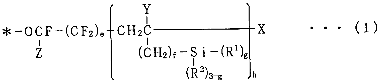
- a fluorine-containing silane compound represented by the following general formula (1) can be used.
- R represents a linear or branched perfluoroalkyl group fl.
- Y is hydrogen or lower alkyl group
- Z is fluorine or trifluoromethyl group
- R 1 is water
- R 2 represents hydrogen or a monovalent hydrocarbon group.
- a, b, c, d, e are integers of 0 or 1 or more, a + b + c + d + e is at least 1 or more, and each repeating unit enclosed by a, b, c, d, e
- the order of presence of is not limited in the formula.
- f represents 0, 1 or 2;
- g represents 1, 2 or 3.
- h represents an integer of 1 or more.
- fluorine-containing silane compound a compound represented by the following general formula (2) may be used.
- R is a formula: (C F) 0 (wherein k is 1
- k is an integer from 2k to 6.
- R 3 is a monovalent hydrocarbon group having 1 to 8 carbon atoms, and X represents a hydrolyzable group or a halogen atom.
- p represents 0, 1 or 2.
- n represents an integer of 1 to 5.
- m and r represent 2 or 3.
- a method of dissolving in an organic solvent and applying it to the spectacle lens surface can be employed.
- a dating method dipping method
- a spin coat method a spray method
- a flow method a doctor blade method
- a roll coat coating a gravure coat coating
- a curtain flow coating etc.
- organic solvent examples include perfluorinated hexane, perfluoromethylcyclohexane, norfluoro 13 dimethylcyclohexane, and the like.
- the concentration of the fluorine-containing silane compound is preferably in the range of 0.03 mass% to 1 mass%.
- concentration of the compound is too low, it is difficult to form an antifouling layer having a sufficient film thickness, so that a sufficient antifouling effect cannot be obtained.
- concentration of the compound is too high, the antifouling layer may be too thick. Therefore, there is a possibility that the burden of performing a rinsing operation for eliminating uneven coating after application of the compound may increase.
- a vacuum vapor deposition method in which the fluorine-containing silane compound is evaporated in a vacuum chamber and adhered to the surface of the spectacle lens may be employed.
- the raw material compound can be used at a high concentration or without a diluting solvent.
- the film thickness of the protective layer is not particularly limited, and is preferably 0.001 to 0.5 m force, more preferably 0.001 to 0.03 / zm. If the film thickness of the antifouling layer is too thin, the antifouling effect will be poor, and conversely if too thick, the surface will be sticky, which is not preferable. In addition, when the antifouling layer is provided on the surface of the antireflection layer, it is not preferable that the antifouling layer is thicker than 0.03 m because the antireflection effect is lowered.
- a mark is printed as an alignment mark serving as a horizontal reference when the target lens is processed as described later. It has been.
- the marking points are a center point 11 indicating the optical center, two horizontal reference marks 12, 13 indicating the horizontal direction of the spectacle lens set to a predetermined astigmatism axis based on prescription, and a force such as printing. Are listed.
- ink that can be removed with an organic solvent such as alcohol is generally used.
- the alignment mark used as the horizontal reference may be represented by a line, mark, etc. in addition to the mark.
- the center point 11 is printed at the optical center position of the spectacle lens L, for example, in the present embodiment, two straight lines having a length of about 3 mm are printed in cross.
- the horizontal reference marks 12 and 13 are formed on a horizontal line passing through the center point 11, for example, in this embodiment, at positions on both sides of the center point 11 that is 16 mm away from the center point 11 and in a circular shape with a diameter of about 2 mm. Printed.
- FIG. 4 is a schematic cross-sectional view of a spectacle lens fixing portion showing an aspect in which the spectacle lens L is processed into a target lens shape
- FIG. 5 is an exploded schematic diagram showing a fixing structure of the spectacle lens L.
- the dimensions and ratios of each component are different from the actual ones for convenience of explanation.
- the spectacle lens L is covered using a target lens shape device 50.
- the target lens shape processing apparatus 50 is composed of a pair of fixing devices including a chuck 51 as one fixing device and a chuck 52 as the other fixing device. , None of which is a clamp shaft, a drive unit, and a drive that controls the operation of the drive unit (not shown). It includes a dynamic control unit, a storage unit for storing frame data, a water supply nozzle, and the like.
- the chuck 51 is provided with a lens holding member 510 made of resin at the tip, and has a function of chucking (fixing) the eyeglass lens L with one force via the adhesive sheet 20 according to the second embodiment.
- the other chuck 52 is provided with an elastic body such as rubber at the tip, and has a function of pressing against the concave surface L2 of the spectacle lens L and fixing.
- the spectacle lens L with the antifouling layer formed on the convex surface L1 is fixed to the fixing device having a pair of chucks 51 and 52. Specifically, the spectacle lens L is fixed by being pressed by the chuck 51 and the other chuck 52 with the convex surface L1 on the chuck 51 side, and the central axis of the fixing device (chuck 51, 52) is the spectacle lens. It is located at the processing center of lens L.
- an adhesive sheet 20 is interposed between the convex surface L1 of the spectacle lens L and the chuck 51 so as to cover the processing center of the spectacle lens L! /
- the pressure-sensitive adhesive sheet 20 has a base material layer 201 having elasticity capable of being compressed by 10% or more in a direction intersecting the lens surface, and a lens-side pressure-sensitive adhesive layer 202 as a first covering layer provided on the lens side of the base material layer 201. And a chuck side adhesive layer 203 as a second coating layer provided on the chuck 51 side of the base material layer 201.
- the chuck 51 and the chuck 52 are connected to the respective clamp shafts, and the driving amount controlled by the drive control unit is operated to control the feeding amount, rotation, and the like directed to the spectacle lens L. .
- the water supply nozzle supplies water to the peripheral portion of the spectacle lens L to be ground during grinding.
- Examples of the material of the base material layer 201 include polyolefin resin such as polyethylene and polypropylene, polyester such as polystyrene and polyethylene terephthalate, polyacetate butyl, ethylene acetate butyl, ABS, polycarbonate, polychlorinated butyl resin, polyamide.
- Thermoplastic resins such as polyimide, acetate, 4-fluorinated styrene, thermosetting resins such as epoxy resin, rubber-based resins such as soft rubber and hard rubber, and materials for reinforcing them, such as fiber
- An example is scab containing a material.
- the base material layer 201 needs to have elasticity capable of being compressed by 10% or more in the direction intersecting the lens surface. That is, when the pressure-sensitive adhesive sheet 20 is clamped by the chuck 51 and the lens convex surface L 1 in order to perform the target force, the thickness of the base material layer 201 is 9% of the original thickness. Compressed to 0% or less. In order to impart such compressive properties to the base material layer 201, for example, it is preferable to foam the above-described rosin or the like with an appropriate foaming agent.
- the foaming method it is preferable to use a foaming agent.
- a volatile foaming agent or a chemical foaming agent can be employed.
- the volatile foaming agent means a volatile liquid or solid that evaporates as the pressure of the high-pressure extrusion of the extruder is released.
- the chemical foaming agent is a compound that decomposes by heating to generate a decomposition gas, and examples thereof include azodicarbonamide (ADCA) and sodium hydrogen carbonate.
- the foaming ratio is arbitrary, and the content of the foaming agent and the foaming method are known in a known manner so that the base material layer 201 has elasticity that can be compressed at a compression rate of 10% or more in the direction intersecting the lens surface. Control is sufficient.
- the base material layer 201 is a foam
- a structure in which a foam layer and a non-foam layer that are not necessarily made of the whole base material layer 201 are laminated may be used.
- the compression rate of the base material layer 201 is preferably 15% or more, more preferably 20% or more, from the viewpoint that the surface of the pressure-sensitive adhesive sheet 20 follows the unevenness of the lens surface. Most preferred is 30% or more. However, if the compression ratio is too high, the base material becomes too thin and the cushioning property is lost, and there is a possibility that the lens may be cracked. Therefore, the compression ratio is preferably 50% or less. .
- the thickness of the base material layer 201 is preferably 0.5 mm or more from the viewpoint that the surface of the pressure-sensitive adhesive sheet 20 follows the irregularities on the lens surface. Most preferably, it is 8 mm or more. However, as the thickness of the base material layer increases, twisting during the lens processing increases and axial misalignment occurs. Therefore, it is preferably 1. Omm or less.
- the strength of the base material layer 201 is determined according to JIS K 7127 “Plastic Film and Sheet Tensile Test Method” (“JIS Handbook Steel” Foundation Japan Standards Association, issued on April 12, 1989).
- the thickness is preferably lkgfZmm 2 (9.8 N / mm 2) or more.
- the tensile modulus of the base layer 201, the value of Em is defined above words 6JIS ⁇ 7127 ⁇ plastic film and the tensile test method of the sheet "is, lkgfZm m 2 or more 450KgfZmm 2 hereinafter (9. 8NZmm 2 or more, 4410NZmm 2 following ) In the range It is preferable.
- the tensile modulus of the base material layer 201 is too small, a large elongation occurs with a small load. As a result, an axis shift may occur. On the other hand, if the tensile modulus of the base material layer 201 is too large, it may not be possible to follow the lens shape.
- the lens-side pressure-sensitive adhesive layer 202 is a pressure-sensitive adhesive containing a polymer mainly composed of (meth) acrylate, a tackifier resin, and a crosslinking agent, like the first coating layer 2bl of the first embodiment. It is formed from an agent composition.
- Adhesive strength of the lens-side adhesive layer 202 must be sufficient for antifouling layers with low surface tension. According to JIS Z 0237 "Adhesive sheet 'Adhesive sheet test method", the 180 degree peeling method is used. In the adhesive strength test method, when a polyethylene terephthalate plate surface-treated with a fluorine-modified silicone release agent is used as a test plate, 4 gf (0.0392N) or more is required, and preferably 6 gf (0.058N) or more. is there.
- the upper limit adhesive strength is preferably 400 gf or less, but is not particularly limited. However, if the adhesive strength of the adhesive sheet is too large, the film such as an antireflection layer formed on the lens surface may be peeled off.
- SUS304 or SUS302 steel plate of 5 to 20 mm cut to a width of 50 mm and a length of 125 mm.
- the manual roller used as a crimping device is coated with a rubber layer with a spring hardness of 80 ⁇ 5Hs and a thickness of about 6mm as specified in J IS K 6301.
- the width is about 45mm, the diameter is about 83mm, and the mass is 2000 ⁇ It shall be 50g.
- the test method for determining the adhesive strength of the pressure-sensitive adhesive sheet 20 in the present embodiment is in accordance with the adhesive strength test method based on the 180-degree peeling method stipulated in the above-mentioned 6JIS Z 02 37 “pressure-sensitive adhesive sheet” pressure-sensitive adhesive sheet test method ”.
- a 3 mm thick polyethylene terephthalate plate surface-treated with a fluorine-modified silicone release agent is used as the test plate.
- a specific method for manufacturing the test plate in the test method of the present embodiment is as follows. First, the thickness of 3 mm, width 50 mm, on the surface of a polyethylene terephthalate plate of length 125 mm, uniformly applying a fluorine-modified silicone releasing agent 0. 3gZ m 2 or more 0.
- the polyethylene terephthalate plate coated with the fluorine-modified silicone release agent is heated at about 150 ° C. for about 60 seconds. After the heating is completed, any one of ethanol, isopropyl alcohol, and acetone is applied as a cleaning solution to the side of the polyethylene terephthalate plate that is covered with the fluorine-modifying silicone release agent. Then, wipe the cleaning solution with gauze. Repeat the application and wiping of such cleaning solution three or more times until it can be visually confirmed that the surface of the test plate is clean.
- X-70-201 manufactured by Shin-Etsu Chemical Co., Ltd. is used as the fluorine-modified silicone release agent.
- Examples of such adhesives that exhibit strong and adhesive strength include rubber adhesives such as natural rubber (polyisoprene), styrene butadiene rubber, butyl rubber, and polyisobutylene, acrylic adhesives, and silicone adhesives. And vinyl acetate pressure sensitive adhesive.
- the thickness of the lens side pressure-sensitive adhesive layer 202 is 1 to: L00 m force S, preferably 3 to 50 m force S. If the thickness of the adhesive layer is less than 1 ⁇ m, the adhesive strength will not be sufficient. If the thickness of the adhesive layer exceeds 100 / zm, the adhesive sheet will be easily displaced in the direction parallel to the lens surface when the lens is chucked (fixed). Therefore, there is a possibility that the lens becomes unstable at the time of the lens shape.
- the chuck side adhesive layer 203 does not need a particularly strong adhesive force as long as it can adhere to the lens holding member 510 made of resin located at the tip of the chuck 51. Therefore, the same adhesive as the lens side adhesive layer 202 may be used as the adhesive, or an adhesive having a different structure may be used! . Further, the thickness may be the same as or different from that of the lens-side pressure-sensitive adhesive layer 202.
- the adhesive layers 202, 203 that are the main parts of the present embodiment are provided on both surfaces of the base material layer 201.
- the area of the pressure-sensitive adhesive sheet 20 is about 700 mm 2 or more. There may be such a shape. Similarly, when the adhesive strength is 8 gf or more, it should have an area of about 400 mm 2 or more. However, it is preferable that the pressure-sensitive adhesive sheet 20 has an area larger than the area of contact with the lens holding member 510.
- the outer shape is smaller than the predetermined target lens shape to be ground.
- the size of the adhesive sheet 20 is preferably about 25 mm, more preferably 30 mm or less.
- the pressure-sensitive adhesive sheet 20 in the second embodiment is made of an acryl-based pressure-sensitive adhesive having a thickness of about 20 m on one side of a base layer 201 having a thickness of about 0.8 mm made of a chloroprene rubber foam (neoprene foam).
- a lens-side pressure-sensitive adhesive layer 202 made of an adhesive agent is provided, and a chuck-side pressure-sensitive adhesive layer 203 made of a rubber-based pressure-sensitive adhesive is provided on the other side of the substrate layer 201.
- the adhesive sheet 20 is at least attached to the convex surface L1 of the spectacle lens formed with the antifouling layer. It has a shape that does not cover the mark points (center point 11 and horizontal reference marks 12, 13) printed on convex surface L1.
- the shape of the pressure-sensitive adhesive sheet 20 in the second embodiment is also an elliptical force with a top and bottom width of 25mm and a width of 40mm, and a central hole as a circular notch that penetrates the pressure-sensitive adhesive sheet 20 from the front and back at the approximate center of the ellipse. And has a shape consisting of notches 24 and 25 formed in a substantially circular shape on the outer periphery of the elliptical horizontal line in the horizontal direction.
- the spectacle lens L can be set on the axis aligner, the mark printed on the convex surface L1 can be visually recognized, and the spectacle lens L can be fixed at a predetermined position. In other words, it can be leveled.
- the notches 24 and 25 are not necessary when the base material of the pressure-sensitive adhesive sheet 20 is a soft and transparent material such as polyvinyl chloride, vinyl resin or the like. (However, the center hole 23 is necessary to prevent the disappearance of the mark.)
- the center hole 23 is a hole for visually recognizing the center point 11 when the adhesive sheet 20 is attached to the convex surface L1 of the spectacle lens L.
- the notches 24 and 25 are horizontal reference marks. It is a notch for visually recognizing 12 and 13. Therefore, corresponding to each mark printed on the convex surface L1 of the spectacle lens L, for example, the diameter of the circular center hole 23 is approximately 6 mm, and the circle forming the notches 24 and 25 has a center hole 23 at the center.
- the shape is approximately 9mm in diameter at a position approximately 16mm away from the center of the center.
- the shape and size of the center hole 23 and the notches 24 and 25 are not limited to this as long as the mark can be visually recognized.
- the area of the adhesive sheet 20 is substantially 630 mm 2, and has an adhesive strength of about logf.
- the outer shape is an elliptical force with a top and bottom width of 30 mm and a width of 40 mm
- the area of the adhesive sheet in which the center hole 23 and the notches 24 and 25 are formed is approximately 800 mm 2 .
- the area of the pressure-sensitive adhesive sheet is about 1050 mm 2 even in the case of a substantially rectangular shape having a top and bottom width of 30 mm and 40 mm. Therefore, a large force of aspect ratios - in order to accommodate the eye type, maximum area of adhesive sheet 20, U,. About 1000 mm 2 is preferred
- the lens holding member 510 is mounted as a tip of the chuck 51 of the lens-shaped carriage device 50, and is mounted and fixed with a cylindrical mounting portion 511 that is positioned and fixed.
- a bowl-shaped lens holding section 512 connected to the section 511 is provided.
- a protrusion 511A is formed for fitting and positioning the lens holding member 510 to the chuck 51 body when the lens holding member 510 is mounted on the chuck 51 body.
- four protrusions 511A are formed for every 90 degrees.
- One of the four protrusions is formed in a size different from that of the other three, and has a function of determining the direction in a predetermined fixed direction when the chuck 51 is mounted on the main body.
- a cup-shaped lens holding surface 512A is formed on the end surface of the lens holding portion 512.
- the adhesive sheet 20 is adhered to the convex surface L1 of the spectacle lens L on which the antifouling layer is formed. Specifically, the approximate center of the center hole 23 of the adhesive sheet 20 and the approximate center of the circle forming the cutouts 24, 25 are in the approximate center of each mark point (center point 11 and horizontal reference marks 12, 13). Place the adhesive sheet 20 on the convex surface L1 so that it is positioned and does not cover each mark (see Fig. 3A and Fig. 3B).
- the adhesive sheet 20 may be attached to the lens holding member 510. Specifically, the adhesive sheet 20 is attached to the lens holding surface 512A so that the approximate center of the center hole 23 of the adhesive sheet 20 and the center of the lens holding surface 512A of the lens holding member 510 are aligned.
- the lens holding member 510 is attached on the pressure-sensitive adhesive sheet 20 as follows to the spectacle lens L having the pressure-sensitive adhesive sheet 20 attached to the convex surface L1.
- the spectacle lens L having the adhesive sheet 20 adhered to the convex surface L1 is set and fixed to a known pivoting device with the adhesive sheet 20 side as the upper surface. So-called leveling is performed.
- the axising device is also called a blocker, and the marking point printed on the convex surface L1 of the spectacle lens L (see Fig. 1), that is, the center point 11 indicating the optical center, and two horizontal reference marks 12 indicating the horizontal direction of the lens, Look at 13 and fix the spectacle lens L in a predetermined position.
- the convex surface L1 of the spectacle lens L has a foam layer so that the opaque adhesive sheet 20 is adhered to the adhesive sheet 20, and the center hole 23 and the notches 24 and 25 are formed. Since the center point 11 and the horizontal reference marks 12 and 13 are attached so as not to be hung, the spectacle lens L can be fixed accurately.
- the adhesive sheet 20 is attached to the lens holding member 510 in the attaching step, the tape is attached and the same operation is performed with the lens in the state.
- a lens holding member 510 is attached on the adhesive sheet 20 of the spectacle lens L fixed to the pivoting device.
- the lens holding member 510 is attached to the outer peripheral surface of the mounting portion 511.
- the four protrusions 511A have protrusions of different sizes in the direction of the eyeglass lens L, which is the upper side when wearing spectacles, and the center axis is the center point 11 of the eyeglass lens L (the center hole 23 of the adhesive sheet 20). (Approximately center).
- the lens holding member 510 is fixed to the arm of the pivoting device, and the lens holding member is attached by pressing the arm to a fixed position on the lens.
- the spectacle lens L held by the lens holding member 510 via the adhesive sheet 20 is attached to the chuck 51 as one fixing device of the lens type cartridge device 50.
- the lens holding member 510 is attached to the chuck 51 so that the four protrusions 511 A formed on the outer peripheral surface of the mounting portion 511 are fitted in a recess (not shown) formed inside the main body of the chuck 51. Inserted into the body.
- the direction of the spectacle lens L to be processed into a lens is determined by the protrusions of different sizes among the four protrusions 511A formed on the outer peripheral surface of the mounting portion 511.
- the chuck 52 as the other fixing device of the target lens shape processing device 50 is fed out by the clamp shaft and pressed against the concave surface L2 of the spectacle lens L. It is done. Thereby, the spectacle lens L is sandwiched and fixed between the chuck 51 and the chuck 52 (see FIG. 4). That is, the adhesive sheet 20 is positioned between the eyeglass lens and the chuck 51.
- the rotating grindstone 60 is pressed against the peripheral edge of the spectacle lens L fixed between the chuck 51 and the chuck 52 and ground into a predetermined shape.
- the grinding is performed to a predetermined shape that fits within the frame of the spectacle frame based on the frame data stored in the storage unit in advance.
- water is supplied to the peripheral edge of the spectacle lens L to supply water, and heat generated by grinding is removed and the grinding powder is washed away.
- the base material layer 201 of the pressure-sensitive adhesive sheet 20 has elasticity that can be compressed by 10% or more in the direction intersecting the lens surface, even if the lens surface is convex, the pressure-sensitive adhesive sheet 20 can be deformed according to its shape. It is possible to maintain a sufficient adhesive force.
- the lens lock tape is not required when processing the target lens shape, and the spectacle lens L can be firmly fixed only by the adhesive sheet 20. Therefore, the lens processing process can be simplified, and the lens can be deviated stably when the lens of the antifouling lens is cast in an eyeglass store. It becomes possible.
- the material of the base material layer 201 is a resin foam (chloroprene rubber foam)
- the compression deformation of the pressure-sensitive adhesive sheet 20 becomes very easy when the eyeglass lens L is chucked.
- the pressure-sensitive adhesive sheet 20 has an area larger than the contact area with the chuck 51, the chuck 51 and the spectacle lens L can sufficiently adhere to each other. Can be fixed stably.
- the adhesive sheet 20 is formed with notches (center hole 23, notches 24, 25) for viewing the markings on the lens surface.
- the lens L can be easily attached to the lens L, and the eyeglass lens L can be easily chucked in the lens cage. Moreover, the sticking position confirmation after chucking can also be performed reliably.
- the pressure-sensitive adhesive sheet 20 includes a foamed layer and is opaque, it is possible to prevent forgetting to remove the pressure-sensitive adhesive sheet 20 after processing the target lens shape.
- the spectacle lens is chucked with a pair of chucks, and a lens shape force check is performed. The degree was observed. Note that this example basically conforms to the above-described embodiment, and details that do not need to be described in particular are omitted.
- An antifouling layer (Seiko Epson Co., Ltd. easy care coat, hyperamenity coat) mainly composed of the above-mentioned fluorine-containing silane compound is formed on the surface of these lenses.
- the shape is the same as that of the pressure-sensitive adhesive sheet 20 in this embodiment. In other words, it consists of an ellipse with a vertical width of 25 mm and a horizontal width of 40 mm, and predetermined notches (23, 24, 25) are formed (see FIG. 1).
- Thickness 0.8mm
- Chloroprene rubber foam (neoprene foam)
- Compression rate 40% (value at the time of chucking (fixed) described later)
- Thickness 20 ⁇
- Adhesive strength lOgf CFIS Z 0237 compliant
- Chuck side adhesive layer lOgf CFIS Z 0237 compliant
- Thickness 20 ⁇
- Adhesive strength 3gf CFIS Z 0237 compliant
- Thickness 0.8mm
- Compression rate 0% (value at the time of chucking (fixed) described later)
- Thickness 20 ⁇
- Adhesive strength lOgf CilS Z 0237 compliant
- Thickness 20 ⁇
- Adhesive strength 3gf CFIS Z 0237 compliant
- an eyeglass lens for processing a lens shape was set on a predetermined lens fixing jig.
- the lens was fixed so that the astigmatism axis was in a specified direction (for example, 180 °).
- a force-eye type frame with a large aspect ratio was prepared and used as a reference frame.
- a predetermined pressure-sensitive adhesive sheet was attached to the convex surface of the eyeglass lens for processing the target lens shape.
- a lens holding member was stuck on pressure-sensitive adhesive sheets A and B, and fixed to a bead processing machine (“LE-8080” manufactured by NIDEK Corporation).
- Adhesive sheet C single-sided adhesive
- a lens lock tape was stuck on the pressure-sensitive adhesive sheet and fixed to the target lens shaper.
- the lens after the lens processing was put into a reference frame, and the displacement of the astigmatic axis was measured with a lens meter. —For each of the lens and + lens, 10 pieces were cast into a lens, and the ratio of the axial deviation exceeding the allowable range was calculated.
- the allowable range of shaft misalignment is ⁇ 2 ° or less.
- Table 2 shows the results of the axial deviation evaluation test.
- the adhesive strength is the value of the lens-side adhesive layer.
- an adhesive sheet 20 may be disposed on both surfaces of the spectacle lens L as shown in FIG.
- antifouling treatment of spectacle lenses is often performed on both sides of the lens, and both sides of the lens are chucked through the adhesive sheet 20 to more reliably prevent the eyeglass lens L from wobbling when the lens lens is in the lens shape. be able to.
- the shape of the notches 24 and 25 may be a circular cutout hole such as the center hole 23 when the area of the adhesive sheet 20 is larger than the spectacle lens L. In this case, after sticking the adhesive sheet 20 to the spectacle lens L, it is desirable to cut off the portion that protrudes from the outer periphery of the lens so as not to cause any troubles during the lens shape calorie.
- the adhesive strength of the adhesive sheet 20 is sufficiently large, the area of the adhesive sheet 20 can be reduced. In this case, the adhesive sheet 20 is applied to the horizontal reference marks (alignment marks) 12 and 13. Therefore, it is not always necessary to provide the notches 24 and 25 as described above.
- the adhesive tapes 2, 20 are used for fixing the spectacle lens.
- the object using the adhesive tapes 2, 20 is not limited to the spectacle lens. This can also be applied to other lenses.
- the present invention can be used for lenses in which the antifouling layer of the fluorine-containing silane compound is not formed on the surface.
- the present invention can be used for the lens shape of other lenses such as eyeglass lenses.
Landscapes
- Engineering & Computer Science (AREA)
- Chemical & Material Sciences (AREA)
- Mechanical Engineering (AREA)
- Organic Chemistry (AREA)
- Ceramic Engineering (AREA)
- Inorganic Chemistry (AREA)
- Chemical Kinetics & Catalysis (AREA)
- Adhesives Or Adhesive Processes (AREA)
- Adhesive Tapes (AREA)
- Laminated Bodies (AREA)
- Grinding And Polishing Of Tertiary Curved Surfaces And Surfaces With Complex Shapes (AREA)
Description



Claims
Priority Applications (4)
| Application Number | Priority Date | Filing Date | Title |
|---|---|---|---|
| EP07742905.8A EP2025461B1 (en) | 2006-05-12 | 2007-05-07 | Pressure sensitive adhesive sheet and method of edging operation |
| JP2008515497A JP4949390B2 (ja) | 2006-05-12 | 2007-05-07 | 粘着シートおよび玉型加工方法 |
| US12/300,601 US20090301654A1 (en) | 2006-05-12 | 2007-05-07 | Pressure Sensitive Adhesive Sheet and Method of Edging Operation |
| CN2007800173403A CN101443156B (zh) | 2006-05-12 | 2007-05-07 | 粘胶片和磨边加工方法 |
Applications Claiming Priority (4)
| Application Number | Priority Date | Filing Date | Title |
|---|---|---|---|
| JP2006133626 | 2006-05-12 | ||
| JP2006-133626 | 2006-05-12 | ||
| JP2006-226223 | 2006-08-23 | ||
| JP2006226223 | 2006-08-23 |
Publications (1)
| Publication Number | Publication Date |
|---|---|
| WO2007132694A1 true WO2007132694A1 (ja) | 2007-11-22 |
Family
ID=38693792
Family Applications (1)
| Application Number | Title | Priority Date | Filing Date |
|---|---|---|---|
| PCT/JP2007/059470 Ceased WO2007132694A1 (ja) | 2006-05-12 | 2007-05-07 | 粘着シートおよび玉型加工方法 |
Country Status (6)
| Country | Link |
|---|---|
| US (1) | US20090301654A1 (ja) |
| EP (1) | EP2025461B1 (ja) |
| JP (1) | JP4949390B2 (ja) |
| KR (1) | KR20090020593A (ja) |
| CN (1) | CN101443156B (ja) |
| WO (1) | WO2007132694A1 (ja) |
Cited By (2)
| Publication number | Priority date | Publication date | Assignee | Title |
|---|---|---|---|---|
| JP2013228437A (ja) * | 2012-04-24 | 2013-11-07 | Hoya Lense Manufacturing Philippine Inc | 眼鏡レンズ、眼鏡レンズの製造方法および処理液 |
| JP2017529250A (ja) * | 2014-08-13 | 2017-10-05 | ローデンシュトック ゲーエムベーハー | 異なる接着域を有するエッジングパッド |
Families Citing this family (11)
| Publication number | Priority date | Publication date | Assignee | Title |
|---|---|---|---|---|
| EP1987917A1 (en) * | 2007-05-03 | 2008-11-05 | Saint-Gobain Performance Plastics Corporation | Ophthalmic blocking pad |
| FR2945358B1 (fr) * | 2009-05-11 | 2011-12-09 | Essilor Int | Produit comportant une lentille ophtalmique souple, et procede de montage d'une telle lentille ophtalmique souple sur un verre de lunettes |
| CN102601429B (zh) * | 2012-03-26 | 2014-06-25 | 台州市好帮手眼镜设备有限公司 | 快速割片机 |
| JP5942725B2 (ja) * | 2012-09-18 | 2016-06-29 | デクセリアルズ株式会社 | 導電性シート |
| KR102210773B1 (ko) * | 2012-12-11 | 2021-02-02 | 에씰로 앙터나시오날 | 광학 렌즈 부재를 테이핑하는 방법 |
| JP6236313B2 (ja) * | 2013-12-26 | 2017-11-22 | ホヤ レンズ タイランド リミテッドHOYA Lens Thailand Ltd | ブロック装置、眼鏡レンズの製造方法およびプログラム |
| TW201605627A (zh) * | 2014-06-17 | 2016-02-16 | 3M新設資產公司 | 拉伸可離型壓敏性黏著劑組成物及物品 |
| AU2019242166A1 (en) * | 2018-03-28 | 2020-10-15 | Nitto Denko Corporation | Undercoat layer-forming composition, undercoat layer, and coating film |
| JP2020097718A (ja) * | 2018-12-13 | 2020-06-25 | 日東電工株式会社 | 粘着剤組成物および粘着シート |
| EP3933872B1 (en) * | 2019-02-28 | 2023-11-01 | OMRON Corporation | Photoelectric sensor and method for manufacturing same |
| CN116285755A (zh) * | 2022-09-09 | 2023-06-23 | 广东硕成科技股份有限公司 | 一种打磨保护胶带及其应用 |
Citations (9)
| Publication number | Priority date | Publication date | Assignee | Title |
|---|---|---|---|---|
| JPH09258003A (ja) | 1996-03-22 | 1997-10-03 | Sumitomo Chem Co Ltd | 防汚性レンズ |
| JPH101645A (ja) * | 1996-06-14 | 1998-01-06 | Sekisui Chem Co Ltd | 発泡ポリウレタン両面粘着テープ |
| JP2001354926A (ja) * | 2000-06-13 | 2001-12-25 | Sekisui Chem Co Ltd | 研磨材固定用両面接着テープ |
| JP2002265890A (ja) * | 2001-03-06 | 2002-09-18 | Idemitsu Petrochem Co Ltd | 粘着テープ用基材、粘着テープ及び封缶テープ |
| JP2003311595A (ja) * | 2002-04-30 | 2003-11-05 | Nitto Denko Corp | メガネ用レンズの研磨方法および該研磨方法で用いられる粘着シート |
| JP2004122302A (ja) * | 2002-10-03 | 2004-04-22 | Vision Megane:Kk | レンズの加工方法 |
| JP2004244585A (ja) * | 2003-02-17 | 2004-09-02 | Nippon Shokubai Co Ltd | 粘着剤組成物および粘着製品 |
| JP2004249454A (ja) | 2003-01-27 | 2004-09-09 | Seiko Epson Corp | 粘着テープ及び玉型加工方法 |
| JP2006299115A (ja) * | 2005-04-21 | 2006-11-02 | Sun A Kaken Co Ltd | 滑り防止用粘着フィルム |
Family Cites Families (1)
| Publication number | Priority date | Publication date | Assignee | Title |
|---|---|---|---|---|
| JP3344613B2 (ja) * | 1994-12-16 | 2002-11-11 | 王子製紙株式会社 | 粘着シート |
-
2007
- 2007-05-07 WO PCT/JP2007/059470 patent/WO2007132694A1/ja not_active Ceased
- 2007-05-07 KR KR1020087029784A patent/KR20090020593A/ko not_active Withdrawn
- 2007-05-07 US US12/300,601 patent/US20090301654A1/en not_active Abandoned
- 2007-05-07 EP EP07742905.8A patent/EP2025461B1/en active Active
- 2007-05-07 JP JP2008515497A patent/JP4949390B2/ja active Active
- 2007-05-07 CN CN2007800173403A patent/CN101443156B/zh active Active
Patent Citations (9)
| Publication number | Priority date | Publication date | Assignee | Title |
|---|---|---|---|---|
| JPH09258003A (ja) | 1996-03-22 | 1997-10-03 | Sumitomo Chem Co Ltd | 防汚性レンズ |
| JPH101645A (ja) * | 1996-06-14 | 1998-01-06 | Sekisui Chem Co Ltd | 発泡ポリウレタン両面粘着テープ |
| JP2001354926A (ja) * | 2000-06-13 | 2001-12-25 | Sekisui Chem Co Ltd | 研磨材固定用両面接着テープ |
| JP2002265890A (ja) * | 2001-03-06 | 2002-09-18 | Idemitsu Petrochem Co Ltd | 粘着テープ用基材、粘着テープ及び封缶テープ |
| JP2003311595A (ja) * | 2002-04-30 | 2003-11-05 | Nitto Denko Corp | メガネ用レンズの研磨方法および該研磨方法で用いられる粘着シート |
| JP2004122302A (ja) * | 2002-10-03 | 2004-04-22 | Vision Megane:Kk | レンズの加工方法 |
| JP2004249454A (ja) | 2003-01-27 | 2004-09-09 | Seiko Epson Corp | 粘着テープ及び玉型加工方法 |
| JP2004244585A (ja) * | 2003-02-17 | 2004-09-02 | Nippon Shokubai Co Ltd | 粘着剤組成物および粘着製品 |
| JP2006299115A (ja) * | 2005-04-21 | 2006-11-02 | Sun A Kaken Co Ltd | 滑り防止用粘着フィルム |
Non-Patent Citations (2)
| Title |
|---|
| "JIS Handbook on Steel", 12 April 1989, JAPANESE STANDARDS ASSOCIATION |
| See also references of EP2025461A4 |
Cited By (2)
| Publication number | Priority date | Publication date | Assignee | Title |
|---|---|---|---|---|
| JP2013228437A (ja) * | 2012-04-24 | 2013-11-07 | Hoya Lense Manufacturing Philippine Inc | 眼鏡レンズ、眼鏡レンズの製造方法および処理液 |
| JP2017529250A (ja) * | 2014-08-13 | 2017-10-05 | ローデンシュトック ゲーエムベーハー | 異なる接着域を有するエッジングパッド |
Also Published As
| Publication number | Publication date |
|---|---|
| KR20090020593A (ko) | 2009-02-26 |
| US20090301654A1 (en) | 2009-12-10 |
| EP2025461A1 (en) | 2009-02-18 |
| CN101443156A (zh) | 2009-05-27 |
| JPWO2007132694A1 (ja) | 2009-09-24 |
| CN101443156B (zh) | 2010-12-01 |
| JP4949390B2 (ja) | 2012-06-06 |
| EP2025461A4 (en) | 2014-01-22 |
| EP2025461B1 (en) | 2021-12-15 |
Similar Documents
| Publication | Publication Date | Title |
|---|---|---|
| WO2007132694A1 (ja) | 粘着シートおよび玉型加工方法 | |
| CN102216407B (zh) | 处理光学透镜用于修边的方法 | |
| CN100560290C (zh) | 周缘加工方法 | |
| US6942746B2 (en) | Lens blocking system | |
| EP1935565A1 (en) | Adhesive tape and method for adhering the adhesive tape | |
| JP4046546B2 (ja) | メガネ用レンズの研磨方法および該研磨方法で用いられる粘着シート | |
| US20080274672A1 (en) | Ophthalmic blocking pad | |
| JP2004122238A (ja) | 眼鏡用レンズの玉型加工に用いる軸ずれ防止キット及びこれを用いた眼鏡用レンズの玉型加工方法 | |
| US7985123B2 (en) | Adhesive tape for fixing lens and method for processing lens using the same | |
| JP2004148444A (ja) | レンズロックシート | |
| JP4544249B2 (ja) | レンズ保持構造及び玉型加工方法 | |
| JP2006299115A (ja) | 滑り防止用粘着フィルム | |
| HK1079150B (en) | Edging method | |
| US20080102740A1 (en) | Pad for Preventing Axial Shift for Use in Grinding of Eyeglass Lens Coated With Fluorine | |
| WO2006003699A1 (ja) | フッ素コートメガネレンズ研削用軸ズレ防止パッド | |
| HK1069558B (en) | Lens blocking system, lens blocking apparatus and method of blocking lenses |
Legal Events
| Date | Code | Title | Description |
|---|---|---|---|
| 121 | Ep: the epo has been informed by wipo that ep was designated in this application |
Ref document number: 07742905 Country of ref document: EP Kind code of ref document: A1 |
|
| WWE | Wipo information: entry into national phase |
Ref document number: 12008502506 Country of ref document: PH |
|
| WWE | Wipo information: entry into national phase |
Ref document number: 200780017340.3 Country of ref document: CN Ref document number: 2008515497 Country of ref document: JP |
|
| NENP | Non-entry into the national phase |
Ref country code: DE |
|
| WWE | Wipo information: entry into national phase |
Ref document number: 2007742905 Country of ref document: EP |
|
| WWE | Wipo information: entry into national phase |
Ref document number: 1020087029784 Country of ref document: KR |
|
| WWE | Wipo information: entry into national phase |
Ref document number: 12300601 Country of ref document: US |