WO2007133535A2 - Electrolytic apparatus with polymeric electrode and methods of preparation and use - Google Patents
Electrolytic apparatus with polymeric electrode and methods of preparation and use Download PDFInfo
- Publication number
- WO2007133535A2 WO2007133535A2 PCT/US2007/011091 US2007011091W WO2007133535A2 WO 2007133535 A2 WO2007133535 A2 WO 2007133535A2 US 2007011091 W US2007011091 W US 2007011091W WO 2007133535 A2 WO2007133535 A2 WO 2007133535A2
- Authority
- WO
- WIPO (PCT)
- Prior art keywords
- carbon
- electrolytic
- electrode
- electrolytic apparatus
- polymeric
- Prior art date
- Legal status (The legal status is an assumption and is not a legal conclusion. Google has not performed a legal analysis and makes no representation as to the accuracy of the status listed.)
- Ceased
Links
Classifications
-
- C—CHEMISTRY; METALLURGY
- C25—ELECTROLYTIC OR ELECTROPHORETIC PROCESSES; APPARATUS THEREFOR
- C25B—ELECTROLYTIC OR ELECTROPHORETIC PROCESSES FOR THE PRODUCTION OF COMPOUNDS OR NON-METALS; APPARATUS THEREFOR
- C25B1/00—Electrolytic production of inorganic compounds or non-metals
- C25B1/01—Products
- C25B1/24—Halogens or compounds thereof
- C25B1/26—Chlorine; Compounds thereof
-
- C—CHEMISTRY; METALLURGY
- C25—ELECTROLYTIC OR ELECTROPHORETIC PROCESSES; APPARATUS THEREFOR
- C25B—ELECTROLYTIC OR ELECTROPHORETIC PROCESSES FOR THE PRODUCTION OF COMPOUNDS OR NON-METALS; APPARATUS THEREFOR
- C25B11/00—Electrodes; Manufacture thereof not otherwise provided for
- C25B11/04—Electrodes; Manufacture thereof not otherwise provided for characterised by the material
- C25B11/042—Electrodes formed of a single material
- C25B11/043—Carbon, e.g. diamond or graphene
-
- C—CHEMISTRY; METALLURGY
- C25—ELECTROLYTIC OR ELECTROPHORETIC PROCESSES; APPARATUS THEREFOR
- C25B—ELECTROLYTIC OR ELECTROPHORETIC PROCESSES FOR THE PRODUCTION OF COMPOUNDS OR NON-METALS; APPARATUS THEREFOR
- C25B11/00—Electrodes; Manufacture thereof not otherwise provided for
- C25B11/04—Electrodes; Manufacture thereof not otherwise provided for characterised by the material
- C25B11/051—Electrodes formed of electrocatalysts on a substrate or carrier
-
- C—CHEMISTRY; METALLURGY
- C02—TREATMENT OF WATER, WASTE WATER, SEWAGE, OR SLUDGE
- C02F—TREATMENT OF WATER, WASTE WATER, SEWAGE, OR SLUDGE
- C02F1/00—Treatment of water, waste water, or sewage
- C02F1/46—Treatment of water, waste water, or sewage by electrochemical methods
- C02F1/461—Treatment of water, waste water, or sewage by electrochemical methods by electrolysis
- C02F1/467—Treatment of water, waste water, or sewage by electrochemical methods by electrolysis by electrochemical disinfection; by electrooxydation or by electroreduction
- C02F1/4672—Treatment of water, waste water, or sewage by electrochemical methods by electrolysis by electrochemical disinfection; by electrooxydation or by electroreduction by electrooxydation
Definitions
- This invention relates to electrolytic apparatus having at least one polymeric electrode and to methods of construction and use thereof and, in particular, to electrolytic apparatus comprising at least one polymeric electrode that electrolytically generates oxidizing species.
- Electrolytically-generated disinfecting solutions have been disclosed.
- Logan, in U.S. Patent No. 2,163,793, disclose electrolytically producing chlorine dioxide.
- Chen et al., in U.S. Patent No. 6,921,521, disclose a method of producing chlorine dioxide that employs alkaline chlorate in a mineral acid medium and urea as a reducing agent.
- Scheper, et al., in U.S. Patent No. 6,921,743, disclose automatic dishwashing compositions containing a halogen dioxide salt and methods for use with electrochemical cells and/or electrolytic devices.
- Price, et al., in U.S. Patent Application Publication No. 2003/0213503, disclose signal-based electrochemical methods for automatic dishwashing.
- the invention relates to an electrolytic apparatus comprising an' electrolytic cell having at least one carbon-filled polymeric electrode.
- the invention relates to a method comprising providing an electrolytic cell having at least one carbon-loaded polymeric electrode.
- FIG. 1 illustrates an electrolytic apparatus in accordance with one or more embodiments of the invention.
- the present invention can provide electrolytic apparatus, systems utilizing one or more electrolytic apparatus, as well as techniques that involve such electrolytic devices.
- one or more embodiments of the invention involve electrolytic devices having at least one polymeric electrode.
- the electrolytic device of the invention can comprise a plurality of polymeric electrodes.
- the electrolytic device can have at least one electrode serving as a cathode comprised of a polymeric material and, optionally, one or more electrodes serving as an anode comprising the same or different polymeric material.
- the polymeric electrode can be considered to be loaded with electrically conductive components.
- the invention provides relatively low cost components compared to conventional electrodes but with comparable performance.
- the polymeric electrode can be a carbon-filled polymeric electrode. Further embodiments can involve utilizing other components that facilitate conduction or conveyance of an applied electric current through the one or more polymeric electrodes of apparatus of the invention.
- the polymeric electrode can further comprise one or more electrical cores or components that provide electrical conductivity throughout the body of the electrode.
- the electrolytic cell can have an anode and a cathode, any one or both can be a polymeric electrode with at least one metallic core embedded therein. The metallic core thus serves to electrically conduct current and reduces the likelihood of resistive gradient through the electrode.
- the electrolytic devices of the invention can be utilized for electrocatalytic generation of one or more products from one or more precursor species.
- Some aspects of the invention involving the various electrolytic devices of the invention can be directed to generating an oxidizing species.
- some aspects of the invention can involve electrolytically generating one or more halogenated oxidizing agent.
- one or more electrolytic embodiments of the invention can involve electrolytically generating a chlorinated, Brominated, or fluorinated compound, or mixtures thereof, that can oxidize one or more target compounds, non-limiting examples of which include, bacteria.
- the various electrolytic embodiments of the invention can be used to generate one or more of chlorine, hypochlorous species, and chlorine dioxide.
- some embodiments of the invention provide an oxidizing species that can be present or carried in a disinfecting solution generated in situ, typically for immediate delivery and use.
- disinfecting refers to at least partially rendering organisms biologically inactive or inert or incapable of further reproduction or colony propagation.
- Electrolytic apparatus 100 can further comprise one or more sources of electrolyte in fluid communication or at least capable of being in fluid communication with electrolytic cell 110.
- a plurality of sources of electrolytic fluids can be utilized to flexibly provide functionalities selectively chosen by an operator of the apparatus.
- the electrolytic apparatus can comprise a first or primary source of a first electrolyte comprising one or more precursor compounds and an alternate or supplemental source of a second electrolyte comprising one or more alternative precursor compounds.
- the electrolyte can further comprise at least one oxidizing agent selected from the group consisting of chlorates, perchlorates, hypohalites, permanganates, chromates, and peroxides.
- the electrolyte can consist of or consist essentially of a halite or a halide such as a chlorite or a chloride.
- the electrolytic cell can be fluidly connected to a source of electrolytic fluid through inlet port 102.
- Cell 110 further comprises at least one outlet port 104 for delivery of a generated product to a point of use.
- Cell 110 has a body 114 containing a cavity 106 which during operation is filled with the electrolyte from the one or more sources of electrolyte having at least one precursor species therein.
- Cell 110 further has an anode 112 connected to a power source 130.
- Body 114 can also serve as a cathode and is illustrated as electrically connected to power source 130 through one or more metallic, conductive cores 115 at least partially embedded within body 114.
- a member 120 can secure and electrically insulate anode 112 from cathodic body 114.
- some electrolytic cells of the invention can comprise a body 114 that serves to contain electrolyte and facilitates electrolytic conversion of a precursor compound into one or more generated oxidizing compounds.
- the body of the electrolytic cell can serve as the anode.
- This aspect of the invention facilitates production of electrolytic cell especially where the polymeric materials are employed.
- some aspects of the invention can provide a castable or moldable electrode configured to contain electrolyte.
- an applied current is conducted through the electrolytic cell to generate one or more desired compounds from the one or more precursor compounds in the electrolytic fluid transferred into cell.
- chlorine dioxide can be generated at or near an electrode, typically at or near the anode, of the electrolytic cell, from a precursor chlorite species in the electrolyte.
- halite compounds can be electrolytically converted to provide a disinfecting or deodorizing solution comprising chlorine dioxide.
- suitable desirable or ancillary reactions may be facilitated including those that generate hypochlorous species, chlorine, and other oxidizing species.
- ancillary oxidizing species may also.be present in the electrolyte.
- the electrical current can be provided by one or more electrical sources.
- the electrical source provides direct current potential of less than about 6 volts but in some cases, less than about 4.5 volts and in still other cases, less than about 3 volts.
- lower potentials can be used to provide sufficient generation of the desired product.
- a minimum potential such as at least about 2 volts, may be preferred to provide at least partial conversion of the precursor compounds into one or more desirable oxidizing products.
- Particularly advantageous embodiments of the electrical source can involve conventional primary cells such as zinc-carbon, alkaline, or lithium based electrochemical cells or batteries as well as secondary or rechargeable batteries such, but not limited to, nickel cadmium or nickel metal hydride, or lithium ion cells.
- the electrical source can comprise one or more cells such as those having size designations of "AA,” “AAA,” “C,” and “D.”
- the electrolytic apparatus comprises a plurality of electrolytic cells
- one or more of the at least one sources of electrolytic fluid can be fluidly connected, or be connectable to the any one of the electrolytic cells.
- one or more components of the electrolytic apparatus can be removed and replaced.
- the source of electrolyte can be removed, accessed or otherwise filled with fresh electrolyte.
- the power source can be replaced or recharged or otherwise be re-energized and thereby further provide electrical current for the cell.
- At least a portion of the generated product solution can then be used to at least partially disinfect or deodorize a point of use such as a surface.
- Delivery of the product solution comprising the one or more generated oxidizing agents can be effected utilizing any suitable technique.
- the generated disinfecting or deodorizing solution can be rendered airborne as an aerosol or be sprayed on at least a portion of the surface desired to be decontaminated.
- the generated solution comprising the one or more oxidizing agents can be transferred into a bath comprising the same or different desirable oxidizing agents.
- the target article can then be immersed therein so as to facilitate oxidizing or inactivation of the target compounds by the one or more oxidizing species.
- the polymeric electrode can utilize any suitable binding component or matrix.
- the electrode can comprise thermoplastic or thermosetting polymeric materials with electroconductive or electroactive components, non-limiting examples include graphite and electrically conductive carbon.
- the polymeric electrode can be formed by injection molding or similar techniques utilized to fabricate polymeric components. Indeed, moldability of the polymeric materials can provide low cost electrodes having increased surface areas, relative to conventional non-polymeric based electrodes, thereby reducing the effective current density and, in some cases, lowering the operating voltage.
- the polymeric electrodes can be configured to have ribs that increase the effective surface area.
- improved cell fluid dynamics can be realized by casting at least a portion of the cell with smooth surfaces and a surface profile that improves mass transfer through the cell and, in some cases, also reduces any tendency for precipitation of calcerous deposits.
- polymeric binders include polyethylene, polypropylene, polystyrene, polytetrafluoroethylene, polyethyleneterephthalate, polyvinylchloride, polycarbonate, nylon, polymethylmethacrylate, and blends or copolymers thereof.
- the polymeric binder can further comprise reinforcing agents such as fibers. In some cases, the reinforcing component can also serve to facilitate electrical conductivity.
- the electrode can comprise a reinforcing metallic core, comprised of for example, copper, connected to the power source.
- a reinforcing metallic core comprised of for example, copper
- at least a portion of the polymeric electrodes can further comprise an electrocatalytic coating.
- Non- limiting examples of which include valve metals, precious metals, platinum group metals, as well as their oxides and mixtures thereof.
- Other coating materials that can be utilized include, for example, Co ⁇ 2 and MnO 2 .
- the electrode can further utilize a reticulated or mesh substrate in the molded electrode.
- the polymeric material can be molded with a titanium mesh.
- the conductive characteristics of the cell can be improved by facilitating further electrical contact points by, for example, using high pressure points and also by utilizing reticulated structures to further enhance contact characteristics.
- the reticulated structures can be comprised of, for example, copper, nickel, aluminum, and silver.
- the various system and techniques of the invention can be used in applications other than in the exemplarily disclosed chlorine dioxide-generating embodiments including, for example, in electrochlorination, generation of mixed oxidants, and swimming pool chlorinators.
- Other applications include use as electrodeionization cathodes.
- This example compares the performance of an electrolytic cell comprising a carbon- loaded polyethylene electrode, from Covalence Specialty Materials Corp. (Franklin, Massachusetts), relative to a cell with a bare titanium electrode.
- the anode in both cells was a titanium mesh electrode with OPTIMA® RUA-SW electroactive coating, from Siemens Corporation (Union, New Jersey).
- the electrode gap was 2 mm.
- the electrolyte solution used was 1 M sodium chloride.
- Table 1 lists the measured potential at various operating current densities. The data shows higher specific resistivity of carbon-loaded polyethylene electrodes relative to titanium cathodes.
- Table 1 Measured cell voltage, in volts, using a carbon-loaded polyethylene cathode or a titanium cathode.
- the polymeric electrodes of Example 1 was modified to improve performance by utilizing metallic components, four aluminum bars, and having several contact points.
- the anode used was a titanium sheet with OPTIMA® RUA electroactive coating, from Siemens Corporation.
- the electrodes gap was 1.6 mm and the electrolyte solution was 1 M sodium chloride.
- Table 2 lists the measured potential with various contact points and shows that increased points of contact can improve cell characteristics because the carbon-loaded can, in some cases, be considered as a polyethylene filled with carbon particles in contact with each other to provide a conductive pathway and to the surface of the electrode.
- Table 2 Measured cell potential using a carbon-loaded polyethylene cathode with several contact points.
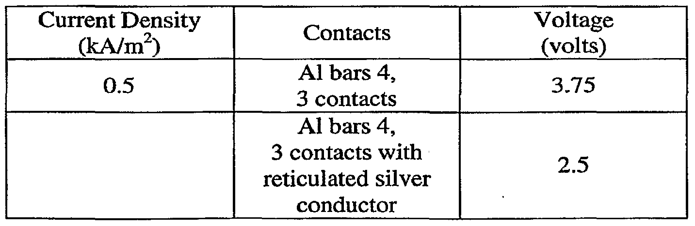
- This example shows the performance of a cell utilizing the carbon-loaded polyethylene cathode of Example 1 and further comprising a silver reticulated structure to facilitate electrical conduction.
- the anode was comprised of titanium sheet catalyzed with OPTIMA® RUA coating.
- the electrodes gap was 1.6 mm and the electrolyte was 1 M sodium chloride.
- Table 3 lists the measured potential with and without the reticulated conductor and shows the improved performance.
- the carbon-loaded polyethylene cathode of Example 1 was treated with agents that reduce surface tension.
- the anode used was a titanium sheet catalyzed with OPTIMA® RUA coating.
- the electrodes gap was 1.6 mm and the electrolyte was sodium chloride.
- the carbon-loaded polyethylene cathode was used with two aluminum bars and two silver strips of reticulated foam and the data presented in Table 4 show that such components facilitate electrical contact by lowering the cell potential. Table 4. Measured cell potential using a carbon-loaded polyethylene cathode with various surface treatments.
- an alternative carbon-based material GRAFCELL® graphite plate, from GrafTech International Ltd. (Parma, Ohio) was used as the cathode. It is believed that the greater carbon content, relative to the carbon-loaded electrode, should provide improved specific resistivity, and lower contact resistance.
- the anode was comprised of titanium sheet catalyzed with OPTIMA® coating. The electrodes gap was 1.6 mm and the electrolyte solution was sodium chloride.
- Table 5 shows the performance of this configuration. Table 5. Cell performance using GRAFCELL® graphite plate cathode over time.
- Example 4 the anode and cathode of Example 4 were modified to evaluate alternative contact configurations.
- the anode comprised of titanium sheet and catalyzed with OPTIMA® coating was sandblasted and two connected at two contact points, without using aluminum contact bars.
- the GRAFCELL® graphite plate cathode was similarly configured to have two contact points.
- a titanium sheet was also used to provide a comparative basis.
- Table 6 lists the measured potentials at various current densities using GRAFCELL® graphite sheet cathode and titanium sheet cathode.
- the electrolyte was 3 M sodium chloride solution.
- the GRAFCELL® sheet was pretreated for 40 hours at 0.5 A/m 2 .
- the data shows comparable performance between the graphite sheet cathode and conventional titanium cathode.
- Example 7 cell was assembled using GRAFCELL® graphite sheet as the cathode and also as the anode.
- the electrodes gap was 1.6 mm and the solution was sodium chloride.
- the operating potential was 3.37 volts.
- Example 8 In this example, the cell as in Example 7 was further modified by platinizing the graphite sheet anode. Under the same operating configuration! the operating voltage was measured to be about 2.99 volts thereby lowering the overvoltage potential.
- the anode of thie electrolytic cell can comprise a carbon-filled polymeric material.
- the examples presented herein involve specific combinations of method acts or system elements, it should be understood that those acts and those elements may be combined in other ways to accomplish the same objectives.
- the term “plurality” refers to two or more items or components.
- the terms “comprising,” “including,” “carrying,” “having,” “containing,” and “involving,” whether in the written description or the claims and the like, are open-ended terms, i.e., to mean “including but not limited to.” Thus, the use of such terms is meant to encompass the items listed thereafter, and equivalents thereof, as well as additional items. Only the transitional phrases “consisting of and “consisting essentially of,” are closed or semi-closed transitional phrases, respectively, with respect to the claims.
Landscapes
- Chemical & Material Sciences (AREA)
- Engineering & Computer Science (AREA)
- Chemical Kinetics & Catalysis (AREA)
- Electrochemistry (AREA)
- Materials Engineering (AREA)
- Metallurgy (AREA)
- Organic Chemistry (AREA)
- Inorganic Chemistry (AREA)
- Electrolytic Production Of Non-Metals, Compounds, Apparatuses Therefor (AREA)
- Electrodes For Compound Or Non-Metal Manufacture (AREA)
- Water Treatment By Electricity Or Magnetism (AREA)
Abstract
Description


Claims
Priority Applications (5)
| Application Number | Priority Date | Filing Date | Title |
|---|---|---|---|
| EP07776872A EP2016639A4 (en) | 2006-05-08 | 2007-05-08 | POLYMER ELECTRODE ELECTROLYTIC APPARATUS AND METHODS OF PREPARATION AND USE |
| JP2009509806A JP2009536689A (en) | 2006-05-08 | 2007-05-08 | Electrolytic device with polymer electrode and method of preparation and use |
| CA002651877A CA2651877A1 (en) | 2006-05-08 | 2007-05-08 | Electrolytic apparatus with polymeric electrode and methods of preparation and use |
| BRPI0709789-1A BRPI0709789A2 (en) | 2006-05-08 | 2007-05-08 | electrolytic apparatus with polymeric electrode and methods of preparation and use |
| MX2008014300A MX2008014300A (en) | 2006-05-08 | 2007-05-08 | Electrolytic apparatus with polymeric electrode and methods of preparation and use. |
Applications Claiming Priority (2)
| Application Number | Priority Date | Filing Date | Title |
|---|---|---|---|
| US74670306P | 2006-05-08 | 2006-05-08 | |
| US60/746,703 | 2006-05-08 |
Publications (2)
| Publication Number | Publication Date |
|---|---|
| WO2007133535A2 true WO2007133535A2 (en) | 2007-11-22 |
| WO2007133535A3 WO2007133535A3 (en) | 2008-01-31 |
Family
ID=38694424
Family Applications (1)
| Application Number | Title | Priority Date | Filing Date |
|---|---|---|---|
| PCT/US2007/011091 Ceased WO2007133535A2 (en) | 2006-05-08 | 2007-05-08 | Electrolytic apparatus with polymeric electrode and methods of preparation and use |
Country Status (8)
| Country | Link |
|---|---|
| US (1) | US20070256932A1 (en) |
| EP (1) | EP2016639A4 (en) |
| JP (1) | JP2009536689A (en) |
| CN (1) | CN101438438A (en) |
| BR (1) | BRPI0709789A2 (en) |
| CA (1) | CA2651877A1 (en) |
| MX (1) | MX2008014300A (en) |
| WO (1) | WO2007133535A2 (en) |
Cited By (1)
| Publication number | Priority date | Publication date | Assignee | Title |
|---|---|---|---|---|
| EP2305610B1 (en) * | 2008-07-31 | 2021-03-24 | Mitsubishi Electric Corporation | Sterilizing/antibacterializing device |
Families Citing this family (4)
| Publication number | Priority date | Publication date | Assignee | Title |
|---|---|---|---|---|
| US20120021303A1 (en) * | 2010-07-21 | 2012-01-26 | Steven Amendola | Electrically rechargeable, metal-air battery systems and methods |
| US8802304B2 (en) | 2010-08-10 | 2014-08-12 | Eos Energy Storage, Llc | Bifunctional (rechargeable) air electrodes comprising a corrosion-resistant outer layer and conductive inner layer |
| EP2792004B1 (en) | 2011-12-14 | 2017-11-08 | Eos Energy Storage, LLC | Electrically rechargeable, metal anode cell and battery systems and methods |
| US10597313B2 (en) | 2017-02-16 | 2020-03-24 | Saudi Arabian Oil Company | Chlorination-assisted coagulation processes for water purification |
Family Cites Families (34)
| Publication number | Priority date | Publication date | Assignee | Title |
|---|---|---|---|---|
| US635622A (en) * | 1899-02-27 | 1899-10-24 | Wilson Waring | Acid-proof bag for fertilizers. |
| US2163793A (en) * | 1937-06-08 | 1939-06-27 | Mathieson Alkall Works Inc | Production of chlorine dioxide |
| US3389200A (en) * | 1966-03-30 | 1968-06-18 | Dow Chemical Co | Process for producing compressed vermicular graphite structures |
| US3507773A (en) * | 1966-12-27 | 1970-04-21 | Kimberly Clark Co | Electrode for use in electrolytes |
| AU414112B2 (en) * | 1969-04-28 | 1971-06-16 | Kimberly-Clark Corporation | Paraffin-active carbon electrode and method of producing same |
| US4502929A (en) * | 1981-06-12 | 1985-03-05 | Raychem Corporation | Corrosion protection method |
| IT1151365B (en) * | 1982-03-26 | 1986-12-17 | Oronzio De Nora Impianti | ANODE FOR ELECTRILYTIC PROCEDURES |
| US4473450A (en) * | 1983-04-15 | 1984-09-25 | Raychem Corporation | Electrochemical method and apparatus |
| DE3423605A1 (en) * | 1984-06-27 | 1986-01-09 | W.C. Heraeus Gmbh, 6450 Hanau | COMPOSITE ELECTRODE, METHOD FOR THEIR PRODUCTION AND THEIR USE |
| US5098543A (en) * | 1985-05-07 | 1992-03-24 | Bennett John E | Cathodic protection system for a steel-reinforced concrete structure |
| DE3610388A1 (en) * | 1986-03-27 | 1987-10-01 | Bernhard Dr Wessling | STABLE ELECTRODES BASED ON MACROMOLECULAR MATERIALS AND METHOD FOR THEIR USE |
| FR2652943B1 (en) * | 1989-10-05 | 1994-07-01 | Electricite De France | CONDUCTIVE MATERIAL FOR ELECTRODE, ELECTRICAL COMPONENT AND MANUFACTURING METHOD THEREOF. |
| US5292411A (en) * | 1990-09-07 | 1994-03-08 | Eltech Systems Corporation | Method and apparatus for cathodically protecting reinforced concrete structures |
| US6132645A (en) * | 1992-08-14 | 2000-10-17 | Eeonyx Corporation | Electrically conductive compositions of carbon particles and methods for their production |
| US5879817A (en) * | 1994-02-15 | 1999-03-09 | Eltech Systems Corporation | Reinforced concrete structure |
| US5478676A (en) * | 1994-08-02 | 1995-12-26 | Rexam Graphics | Current collector having a conductive primer layer |
| CZ37998A3 (en) * | 1995-08-09 | 1998-07-15 | The Procter & Gamble Company | Cleansing and disinfectant preparations containing ionic substances enhancing the disinfection activity |
| US5973913A (en) * | 1997-08-12 | 1999-10-26 | Covalent Associates, Inc. | Nonaqueous electrical storage device |
| US6139705A (en) * | 1998-05-06 | 2000-10-31 | Eltech Systems Corporation | Lead electrode |
| US6395153B1 (en) * | 1998-12-02 | 2002-05-28 | Eltech Systems Corporation | Diaphragm cell |
| US6733639B2 (en) * | 2000-11-13 | 2004-05-11 | Akzo Nobel N.V. | Electrode |
| US20030042134A1 (en) * | 2001-06-22 | 2003-03-06 | The Procter & Gamble Company | High efficiency electrolysis cell for generating oxidants in solutions |
| US7048842B2 (en) * | 2001-06-22 | 2006-05-23 | The Procter & Gamble Company | Electrolysis cell for generating chlorine dioxide |
| US6436345B1 (en) * | 2001-03-23 | 2002-08-20 | Chemtreat, Inc. | Method for generating chlorine dioxide |
| US6921743B2 (en) * | 2001-04-02 | 2005-07-26 | The Procter & Gamble Company | Automatic dishwashing compositions containing a halogen dioxide salt and methods for use with electrochemical cells and/or electrolytic devices |
| US7008523B2 (en) * | 2001-07-16 | 2006-03-07 | Miox Corporation | Electrolytic cell for surface and point of use disinfection |
| US20040149571A1 (en) * | 2001-09-06 | 2004-08-05 | The Procter & Gamble Company | Electrolysis cell for generating halogen (and particularly chlorine) dioxide in an appliance |
| US6991876B2 (en) * | 2001-10-05 | 2006-01-31 | Sri International | Metal/active oxygen batteries |
| US7413637B2 (en) * | 2002-05-17 | 2008-08-19 | The Procter And Gamble Company | Self-contained, self-powered electrolytic devices for improved performance in automatic dishwashing |
| US20030213503A1 (en) * | 2002-05-17 | 2003-11-20 | The Procter & Gamble Company | Signal-based electrochemical methods for automatic dishwashing |
| US6869518B2 (en) * | 2002-06-12 | 2005-03-22 | Ecolab Inc. | Electrochemical generation of chlorine dioxide |
| CN1247448C (en) * | 2002-10-21 | 2006-03-29 | 绵阳高新区鑫天科技有限公司 | Process for preparing ClO2 and coproducing organic salts and(or) compound fertilizer simultaneously |
| US7083708B2 (en) * | 2003-07-31 | 2006-08-01 | The Regents Of The University Of California | Oxygen-consuming chlor alkali cell configured to minimize peroxide formation |
| US7179363B2 (en) * | 2003-08-12 | 2007-02-20 | Halox Technologies, Inc. | Electrolytic process for generating chlorine dioxide |
-
2007
- 2007-05-08 CN CNA200780016601XA patent/CN101438438A/en active Pending
- 2007-05-08 US US11/745,743 patent/US20070256932A1/en not_active Abandoned
- 2007-05-08 WO PCT/US2007/011091 patent/WO2007133535A2/en not_active Ceased
- 2007-05-08 JP JP2009509806A patent/JP2009536689A/en active Pending
- 2007-05-08 BR BRPI0709789-1A patent/BRPI0709789A2/en not_active IP Right Cessation
- 2007-05-08 CA CA002651877A patent/CA2651877A1/en not_active Abandoned
- 2007-05-08 MX MX2008014300A patent/MX2008014300A/en unknown
- 2007-05-08 EP EP07776872A patent/EP2016639A4/en not_active Withdrawn
Non-Patent Citations (1)
| Title |
|---|
| See references of EP2016639A4 * |
Cited By (1)
| Publication number | Priority date | Publication date | Assignee | Title |
|---|---|---|---|---|
| EP2305610B1 (en) * | 2008-07-31 | 2021-03-24 | Mitsubishi Electric Corporation | Sterilizing/antibacterializing device |
Also Published As
| Publication number | Publication date |
|---|---|
| EP2016639A2 (en) | 2009-01-21 |
| CA2651877A1 (en) | 2007-11-22 |
| MX2008014300A (en) | 2008-11-26 |
| WO2007133535A3 (en) | 2008-01-31 |
| EP2016639A4 (en) | 2011-09-14 |
| US20070256932A1 (en) | 2007-11-08 |
| JP2009536689A (en) | 2009-10-15 |
| BRPI0709789A2 (en) | 2011-07-26 |
| CN101438438A (en) | 2009-05-20 |
Similar Documents
| Publication | Publication Date | Title |
|---|---|---|
| EP0071443B1 (en) | Device for waste water treatment | |
| EP2035599B1 (en) | Electrode, method of manufacture and use thereof | |
| EP1340841A1 (en) | Electrolytic cell for ozone generation | |
| US20070141434A1 (en) | Sanitizing Device and Associated Method Using Electrochemically Produced Sanitizing Agents | |
| US20070256932A1 (en) | Electrolytic apparatus with polymeric electrode and methods of preparation and use | |
| US7056424B2 (en) | Cathode for electrochemical regeneration of permanganate etching solutions | |
| CN102101707B (en) | Three-dimensional Electrode Electrocatalytic Oxidation Reactor for Wastewater Degradation | |
| EP2965379A1 (en) | Alkali metal intercalation material as an electrode in an electrolytic cell | |
| JPH0821385B2 (en) | Flow-porous electrode | |
| CN1847466B (en) | Insoluble anode | |
| CN1435512A (en) | Ozone producing electrolyzer | |
| JPH10106900A (en) | Electrode for electric double layer capacitor | |
| US20070045107A1 (en) | Electrolytic cell and method of assembling and operation of an electrolytic cell | |
| CN110404086A (en) | A foldable electrolytic disinfection device | |
| JP2007070701A (en) | Solid polymer electrolyte type ozone generation apparatus | |
| WO2002055440A1 (en) | Electrolytic bath for cartridge electrode | |
| CN212375401U (en) | Space sterilizer capable of generating effective chlorine through electrolysis without cavity division | |
| JP2018166050A (en) | Secondary battery | |
| KR101891161B1 (en) | Electrolytic sterilizing·reduced water production equipment | |
| JP2006205016A (en) | How to get ozone water | |
| WO2007086517A1 (en) | Method and apparatus for synthesizing hypochlorous acid | |
| JP2012021221A (en) | ELECTROLYSIS OF NaCl AQUEOUS SOLUTION BY CYLINDRICAL ELECTRODE OF CARBON FIBER OR CARBON | |
| JP2002248477A (en) | Electrochemical water treatment method | |
| HK1051222B (en) | Cathode for electrochemical regeneration of permanganate etching solutions | |
| JP2005032690A (en) | Battery having self-recovery capability |
Legal Events
| Date | Code | Title | Description |
|---|---|---|---|
| 121 | Ep: the epo has been informed by wipo that ep was designated in this application |
Ref document number: 07776872 Country of ref document: EP Kind code of ref document: A2 |
|
| DPE1 | Request for preliminary examination filed after expiration of 19th month from priority date (pct application filed from 20040101) | ||
| WWE | Wipo information: entry into national phase |
Ref document number: 2007776872 Country of ref document: EP |
|
| WWE | Wipo information: entry into national phase |
Ref document number: 4466/KOLNP/2008 Country of ref document: IN |
|
| WWE | Wipo information: entry into national phase |
Ref document number: 2651877 Country of ref document: CA |
|
| WWE | Wipo information: entry into national phase |
Ref document number: MX/a/2008/014300 Country of ref document: MX Ref document number: 200780016601.X Country of ref document: CN Ref document number: 2009509806 Country of ref document: JP |
|
| NENP | Non-entry into the national phase |
Ref country code: DE |
|
| ENP | Entry into the national phase |
Ref document number: PI0709789 Country of ref document: BR Kind code of ref document: A2 Effective date: 20081107 |