WO2008001861A1 - Zoom lens and imaging device - Google Patents
Zoom lens and imaging device Download PDFInfo
- Publication number
- WO2008001861A1 WO2008001861A1 PCT/JP2007/063027 JP2007063027W WO2008001861A1 WO 2008001861 A1 WO2008001861 A1 WO 2008001861A1 JP 2007063027 W JP2007063027 W JP 2007063027W WO 2008001861 A1 WO2008001861 A1 WO 2008001861A1
- Authority
- WO
- WIPO (PCT)
- Prior art keywords
- lens
- lens group
- refractive power
- negative refractive
- object side
- Prior art date
- Legal status (The legal status is an assumption and is not a legal conclusion. Google has not performed a legal analysis and makes no representation as to the accuracy of the status listed.)
- Ceased
Links
Classifications
-
- G—PHYSICS
- G02—OPTICS
- G02B—OPTICAL ELEMENTS, SYSTEMS OR APPARATUS
- G02B15/00—Optical objectives with means for varying the magnification
- G02B15/14—Optical objectives with means for varying the magnification by axial movement of one or more lenses or groups of lenses relative to the image plane for continuously varying the equivalent focal length of the objective
- G02B15/16—Optical objectives with means for varying the magnification by axial movement of one or more lenses or groups of lenses relative to the image plane for continuously varying the equivalent focal length of the objective with interdependent non-linearly related movements between one lens or lens group, and another lens or lens group
- G02B15/177—Optical objectives with means for varying the magnification by axial movement of one or more lenses or groups of lenses relative to the image plane for continuously varying the equivalent focal length of the objective with interdependent non-linearly related movements between one lens or lens group, and another lens or lens group having a negative front lens or group of lenses
-
- G—PHYSICS
- G02—OPTICS
- G02B—OPTICAL ELEMENTS, SYSTEMS OR APPARATUS
- G02B9/00—Optical objectives characterised both by the number of the components and their arrangements according to their sign, i.e. + or -
- G02B9/34—Optical objectives characterised both by the number of the components and their arrangements according to their sign, i.e. + or - having four components only
-
- G—PHYSICS
- G02—OPTICS
- G02B—OPTICAL ELEMENTS, SYSTEMS OR APPARATUS
- G02B15/00—Optical objectives with means for varying the magnification
- G02B15/14—Optical objectives with means for varying the magnification by axial movement of one or more lenses or groups of lenses relative to the image plane for continuously varying the equivalent focal length of the objective
- G02B15/144—Optical objectives with means for varying the magnification by axial movement of one or more lenses or groups of lenses relative to the image plane for continuously varying the equivalent focal length of the objective having four groups only
- G02B15/1441—Optical objectives with means for varying the magnification by axial movement of one or more lenses or groups of lenses relative to the image plane for continuously varying the equivalent focal length of the objective having four groups only the first group being positive
- G02B15/144113—Optical objectives with means for varying the magnification by axial movement of one or more lenses or groups of lenses relative to the image plane for continuously varying the equivalent focal length of the objective having four groups only the first group being positive arranged +-++
-
- G—PHYSICS
- G02—OPTICS
- G02B—OPTICAL ELEMENTS, SYSTEMS OR APPARATUS
- G02B15/00—Optical objectives with means for varying the magnification
- G02B15/14—Optical objectives with means for varying the magnification by axial movement of one or more lenses or groups of lenses relative to the image plane for continuously varying the equivalent focal length of the objective
- G02B15/145—Optical objectives with means for varying the magnification by axial movement of one or more lenses or groups of lenses relative to the image plane for continuously varying the equivalent focal length of the objective having five groups only
- G02B15/1455—Optical objectives with means for varying the magnification by axial movement of one or more lenses or groups of lenses relative to the image plane for continuously varying the equivalent focal length of the objective having five groups only the first group being negative
- G02B15/145513—Optical objectives with means for varying the magnification by axial movement of one or more lenses or groups of lenses relative to the image plane for continuously varying the equivalent focal length of the objective having five groups only the first group being negative arranged --++-
-
- G—PHYSICS
- G02—OPTICS
- G02B—OPTICAL ELEMENTS, SYSTEMS OR APPARATUS
- G02B15/00—Optical objectives with means for varying the magnification
- G02B15/14—Optical objectives with means for varying the magnification by axial movement of one or more lenses or groups of lenses relative to the image plane for continuously varying the equivalent focal length of the objective
- G02B15/16—Optical objectives with means for varying the magnification by axial movement of one or more lenses or groups of lenses relative to the image plane for continuously varying the equivalent focal length of the objective with interdependent non-linearly related movements between one lens or lens group, and another lens or lens group
- G02B15/163—Optical objectives with means for varying the magnification by axial movement of one or more lenses or groups of lenses relative to the image plane for continuously varying the equivalent focal length of the objective with interdependent non-linearly related movements between one lens or lens group, and another lens or lens group having a first movable lens or lens group and a second movable lens or lens group, both in front of a fixed lens or lens group
- G02B15/167—Optical objectives with means for varying the magnification by axial movement of one or more lenses or groups of lenses relative to the image plane for continuously varying the equivalent focal length of the objective with interdependent non-linearly related movements between one lens or lens group, and another lens or lens group having a first movable lens or lens group and a second movable lens or lens group, both in front of a fixed lens or lens group having an additional fixed front lens or group of lenses
- G02B15/173—Optical objectives with means for varying the magnification by axial movement of one or more lenses or groups of lenses relative to the image plane for continuously varying the equivalent focal length of the objective with interdependent non-linearly related movements between one lens or lens group, and another lens or lens group having a first movable lens or lens group and a second movable lens or lens group, both in front of a fixed lens or lens group having an additional fixed front lens or group of lenses arranged +-+
-
- G—PHYSICS
- G02—OPTICS
- G02B—OPTICAL ELEMENTS, SYSTEMS OR APPARATUS
- G02B9/00—Optical objectives characterised both by the number of the components and their arrangements according to their sign, i.e. + or -
- G02B9/12—Optical objectives characterised both by the number of the components and their arrangements according to their sign, i.e. + or - having three components only
- G02B9/14—Optical objectives characterised both by the number of the components and their arrangements according to their sign, i.e. + or - having three components only arranged + - +
Definitions
- the present invention relates to a zoom lens and an image pickup apparatus using the zoom lens as an image pickup lens. More specifically, the present invention relates to a solid state device such as a CCD (Charge Coupled Device) or a CMOS (Complementary Metal-Oxide Semiconductor). The present invention relates to a zoom lens having a zoom ratio of about 3 times and an image pickup apparatus using this zoom lens, which is suitable for a mobile phone with a camera and a digital still camera using an image sensor.
- a solid state device such as a CCD (Charge Coupled Device) or a CMOS (Complementary Metal-Oxide Semiconductor).
- the present invention relates to a zoom lens having a zoom ratio of about 3 times and an image pickup apparatus using this zoom lens, which is suitable for a mobile phone with a camera and a digital still camera using an image sensor.
- the zoom lenses disclosed in Japanese Patent Application Laid-Open Nos. 2000-131610 and 2004-354869 are arranged in order from the object side and have a first lens group having positive refractive power, negative A second lens group having a positive refractive power, a third lens group having a positive refractive power, and a fourth lens group having a positive refractive power, and a prism that bends the optical path is disposed in the first lens group.
- This zoom lens is designed to be thin in the direction of the incident optical axis.
- this type of zoom lens has been insufficient in terms of miniaturization in consideration of mounting on a small imaging device such as a camera-equipped mobile phone whose optical total length is still long.
- the present invention has been made in view of the above-described problems, and has a good optical performance corresponding to a high-pixel image pickup device with a simple configuration, and a small and thin zoom. It is an object of the present invention to provide an image pickup apparatus using a zoom lens and the zoom lens.
- the zoom lens according to an embodiment of the first aspect of the present invention includes, in order from the object side, a first lens group having a weak refractive power, a second lens group having a negative refractive power, and a positive refraction.
- a third lens group having a power and a fourth lens group having a positive refractive power are configured to perform zooming by moving the second lens group and the third lens group.
- the first lens group includes, in order from the object side, a single lens having a negative refractive power, a prism that bends an optical path, and a single lens having a positive refractive power, and the second lens group. Is composed of a single single lens having negative refractive power, and satisfies the following conditional expression (1).
- t2 is the center thickness of the single lens having negative refractive power constituting the second lens group
- fw is the focal length of the entire lens system at the wide angle end.
- a zoom lens according to an embodiment of the second invention of the present invention includes, in order from the object side, a first lens group having a weak refractive power, a second lens group having a negative refractive power, and a positive refraction.
- a third lens group having a power and a fourth lens group having a positive refractive power, and zooming is performed by moving the second lens group, the third lens group, and the fourth lens group.
- the first lens group is configured by arranging, in order from the object side, a single lens having negative refractive power, a prism that bends the optical path, and a single lens having positive refractive power
- the second lens group is composed of a single single lens having negative refractive power, and satisfies the following conditional expression (1).
- t2 is the center thickness of the single lens having negative refractive power constituting the second lens group
- fw is the focal length of the entire lens system at the wide angle end.
- a zoom lens according to an embodiment of the third aspect of the present invention includes, in order from the object side, a first lens group having a weak refractive power, a second lens group having a negative refractive power, and a positive refraction.
- a third lens group having a power and a fourth lens group having a positive refractive power are configured to perform zooming by moving the second lens group and the third lens group.
- the first lens group includes, in order from the object side, a lens prism that has a negative refractive power and bends the optical path, and a single lens that has a positive refractive power, and the second lens group is negative. It is composed of a single lens having a refractive power, and satisfies the following conditional expression (1).
- t2 is the center thickness of the single lens having negative refractive power constituting the second lens group
- fw is the focal length of the entire lens system at the wide angle end.
- a zoom lens according to an embodiment of the fourth aspect of the present invention includes, in order from the object side, a first lens group having a weak refractive power, a second lens group having a negative refractive power, and a positive refraction.
- a third lens group having a power and a fourth lens group having a positive refractive power, and zooming is performed by moving the second lens group, the third lens group, and the fourth lens group.
- the first lens group is configured by arranging, in order from the object side, a lens prism that has a negative refractive power and bends the optical path, and a single lens that has a positive refractive power.
- the two lens group is composed of one single lens having negative refractive power and satisfies the following conditional expression (1).
- t2 is the center thickness of the single lens having negative refractive power constituting the second lens group
- fw is the focal length of the entire lens system at the wide angle end.
- an imaging apparatus includes a zoom lens and an imaging element that converts an optical image formed by the zoom lens into an electrical signal
- the zoom lens includes an object In order from the side, a first lens group having a weak refractive power, a second lens group having a negative refractive power, a third lens group having a positive refractive power, and a fourth lens group having a positive refractive power By moving the second lens group and the third lens group.
- the first lens group includes, in order from the object side, a single lens having a negative refractive power, a prism that bends the optical path, and a single lens having a positive refractive power.
- conditional expression (l) t2Zfw is 0.4, where t2 is the center thickness of a single lens having negative refractive power constituting the second lens group, and fw is the focal length of the entire lens system at the wide angle end. Satisfied.
- An image pickup apparatus includes a zoom lens and an image pickup element that converts an optical image formed by the zoom lens into an electric signal, and the zoom lens is from the object side.
- a first lens group having a weak refractive power a second lens group having a negative refractive power, a third lens group having a positive refractive power, and a fourth lens group having a positive refractive power.
- a single lens having a negative refractive power, a prism that bends the optical path, and a single lens having a positive refractive power are arranged, and the second lens group is a single lens having a negative refractive power.
- t2 is the negative that forms the second lens group. Center thickness of the single lens having a rupture strength, as the focal length of the whole lens system at the wide angle end to fw, thereby satisfying the expression (l) t2Zfw rather 0.4.
- An image pickup apparatus includes a zoom lens and an image pickup element that converts an optical image formed by the zoom lens into an electrical signal, and the zoom lens is from the object side.
- a first lens group having a weak refractive power a second lens group having a negative refractive power
- a third lens group having a positive refractive power a fourth lens group having a positive refractive power.
- the first lens group has a negative refractive power in order from the object side.
- the center thickness and fw satisfy the conditional expression (l) t2Zfw + 0.4.
- An imaging apparatus includes a zoom lens and an imaging element that converts an optical image formed by the zoom lens into an electrical signal, and the zoom In order from the object side, the lens has a first lens group having a weak refractive power, a second lens group having a negative refractive power, a third lens group having a positive refractive power, and a positive refractive power.
- a fourth lens group and is configured to perform zooming by moving the second lens group, the third lens group, and the fourth lens group, and the first lens group
- a lens prism that has negative refractive power and bends the optical path and a single lens that has positive refractive power are arranged in order of the object side force
- the second lens group is a single lens having negative refractive power.
- the present invention although it has a simple configuration, it has good optical performance corresponding to an image sensor with a high pixel, and can be configured to be small and thin.
- FIG. 1 is a diagram showing a lens configuration of a zoom lens according to a first embodiment of the first invention in the present invention.
- FIG. 2 is an aberration diagram of Numerical Example 1 in which specific numerical values are applied to the first embodiment together with FIG. 3 and FIG. 4, and this diagram shows spherical aberration and astigmatism at the wide angle end. This indicates distortion.
- FIG. 3 shows spherical aberration, astigmatism, and distortion at the intermediate focal length.
- FIG. 4 shows spherical aberration, astigmatism, and distortion at the telephoto end.
- FIG. 5 is a diagram showing a lens configuration of a second embodiment of the zoom lens according to the first invention.
- FIG. 6 is an aberration diagram of Numerical Example 2 in which specific numerical values are applied to the second embodiment together with FIGS. 7 and 8, and FIG. 6 shows spherical aberration and astigmatism at the wide angle end. This indicates distortion.
- FIG. 7 shows spherical aberration, astigmatism, and distortion at the intermediate focal length.
- FIG. 8 shows spherical aberration, astigmatism, and distortion at the telephoto end.
- FIG. 9 is a diagram showing a lens configuration of a third embodiment of the zoom lens according to the first invention.
- FIG. 10 is an aberration diagram of Numerical Example 3 in which specific numerical values are applied to the third embodiment together with FIGS. 11 and 12, and FIG. 10 shows spherical aberration and astigmatism at the wide angle end. This indicates distortion.
- FIG. 11 shows spherical aberration, astigmatism, and distortion at the intermediate focal length.
- FIG. 12 shows spherical aberration, astigmatism, and distortion at the telephoto end.
- FIG. 13 is a diagram showing a lens configuration of a fourth embodiment of a zoom lens according to the first invention.
- FIG. 14 is an aberration diagram of Numerical Example 4 in which specific numerical values are applied to the fourth embodiment together with FIGS. 15 and 16, and FIG. 14 shows spherical aberration and astigmatism at the wide angle end. This indicates distortion.
- FIG. 15 shows spherical aberration, astigmatism, and distortion at the intermediate focal length.
- FIG. 16 shows spherical aberration, astigmatism, and distortion at the telephoto end.
- FIG. 17 is a diagram showing a lens configuration of a fifth embodiment of a zoom lens according to the first invention.
- FIG. 18 is an aberration diagram of Numerical Example 5 in which specific numerical values are applied to the fifth embodiment together with FIGS. 19 and 20, and FIG. 18 shows spherical aberration and astigmatism at the wide angle end. This indicates distortion.
- FIG. 19 shows spherical aberration, astigmatism, and distortion at the intermediate focal length.
- FIG. 20 shows spherical aberration, astigmatism, and distortion at the telephoto end.
- FIG. 21 is a diagram showing a lens configuration of a sixth embodiment of the zoom lens according to the first invention.
- FIG. 22 is an aberration diagram of Numerical Example 6 in which specific numerical values are applied to the sixth embodiment together with FIGS. 23 and 24.
- FIG. 22 shows spherical aberration and astigmatism at the wide angle end. , Distortion Is shown.
- FIG. 23 shows spherical aberration, astigmatism, and distortion at the intermediate focal length.
- FIG. 24 shows spherical aberration, astigmatism, and distortion at the telephoto end.
- FIG. 25 is a diagram showing a lens configuration of a first embodiment of a zoom lens according to the second invention of the present invention.
- FIG. 26 is an aberration diagram of Numerical Example 1 in which specific numerical values are applied to the first embodiment together with FIGS. 27 and 28.
- FIG. 26 shows spherical aberration and astigmatism at the wide angle end. This indicates distortion.
- FIG. 27 shows spherical aberration, astigmatism, and distortion at the intermediate focal length.
- FIG. 28 shows spherical aberration, astigmatism, and distortion at the telephoto end.
- FIG. 29 is a diagram showing a lens configuration of a second embodiment of a zoom lens according to the second invention.
- FIG. 30 is an aberration diagram of Numerical Example 2 in which specific numerical values are applied to the second embodiment together with FIGS. 31 and 32.
- FIG. 30 shows spherical aberration and astigmatism at the wide angle end. This indicates distortion.
- FIG. 31 shows spherical aberration, astigmatism, and distortion at the intermediate focal length.
- FIG. 32 shows spherical aberration, astigmatism, and distortion at the telephoto end.
- FIG. 33 is a diagram showing a lens configuration of a third embodiment of a zoom lens according to the second invention.
- FIG. 34 is an aberration diagram of Numerical Example 3 in which specific numerical values are applied to the third embodiment together with FIGS. 35 and 36. This diagram shows spherical aberration and astigmatism at the wide angle end. This indicates distortion.
- FIG. 35 shows spherical aberration, astigmatism and distortion at the intermediate focal length.
- FIG. 36 shows spherical aberration, astigmatism, and distortion at the telephoto end.
- FIG. 37 is a diagram showing a lens configuration of a fourth embodiment of a zoom lens according to the second invention.
- FIG. 38 is an aberration diagram of Numerical Example 4 in which specific numerical values are applied to the fourth embodiment together with FIGS. 39 and 40, and shows the spherical aberration and astigmatism at the wide angle end. This indicates distortion.
- FIG. 39 shows spherical aberration, astigmatism, and distortion at the intermediate focal length.
- FIG. 40 shows spherical aberration, astigmatism, and distortion at the telephoto end.
- FIG. 41 is a diagram showing a lens configuration of a zoom lens according to a first embodiment of the third invention in the present invention.
- FIG. 42 is an aberration diagram of Numerical Example 1 in which specific numerical values are applied to the first embodiment together with FIGS. 43 and 44.
- FIG. 42 shows spherical aberration and astigmatism at the wide angle end. This indicates distortion.
- FIG. 43 shows spherical aberration, astigmatism, and distortion at the intermediate focal length.
- FIG. 44 shows spherical aberration, astigmatism, and distortion at the telephoto end.
- FIG. 45 is a diagram showing a lens configuration of a second embodiment of a zoom lens according to the third invention.
- FIG. 46 is an aberration diagram of Numerical Example 2 in which specific numerical values are applied to the second embodiment together with FIGS. 47 and 48.
- FIG. 46 shows spherical aberration and astigmatism at the wide angle end. This indicates distortion.
- FIG. 47 shows spherical aberration, astigmatism, and distortion at the intermediate focal length.
- FIG. 48 shows spherical aberration, astigmatism, and distortion at the telephoto end.
- FIG. 49 is a diagram showing a lens configuration of a third embodiment of a zoom lens according to the third invention.
- FIG. 50 is an aberration diagram of Numerical Example 3 in which specific numerical values are applied to the third embodiment together with FIGS. 51 and 52.
- FIG. 50 shows spherical aberration and astigmatism at the wide angle end. , Distortion Is shown.
- FIG. 51 shows spherical aberration, astigmatism and distortion at the intermediate focal length.
- FIG. 52 shows spherical aberration, astigmatism, and distortion at the telephoto end.
- FIG. 53 is a diagram showing a lens configuration of a first embodiment of a zoom lens according to the fourth invention of the present invention.
- FIG. 54 is an aberration diagram of Numerical Example 1 in which specific numerical values are applied to the first embodiment together with FIGS. 55 and 56.
- FIG. 54 shows spherical aberration and astigmatism at the wide angle end. This indicates distortion.
- FIG. 55 shows spherical aberration, astigmatism and distortion at the intermediate focal length.
- FIG. 56 shows spherical aberration, astigmatism, and distortion at the telephoto end.
- FIG. 57 is a diagram showing a lens configuration of a second embodiment of a zoom lens according to the fourth invention.
- FIG. 58 is an aberration diagram of Numerical Example 2 in which specific numerical values are applied to the second embodiment together with FIGS. 59 and 60.
- FIG. 58 shows spherical aberration and astigmatism at the wide angle end. This indicates distortion.
- FIG. 59 shows spherical aberration, astigmatism, and distortion at the intermediate focal length.
- FIG. 60 shows spherical aberration, astigmatism, and distortion at the telephoto end.
- FIG. 61 is a diagram showing a lens configuration of a third embodiment of a zoom lens according to the fourth invention.
- FIG. 62 is an aberration diagram of Numerical Example 3 in which specific numerical values are applied to the third embodiment together with FIGS. 63 and 64.
- FIG. 62 shows spherical aberration and astigmatism at the wide angle end. This indicates distortion.
- FIG. 63 shows spherical aberration, astigmatism, and distortion at the intermediate focal length.
- FIG. 64 shows spherical aberration, astigmatism, and distortion at the telephoto end.
- FIG. 65 shows an embodiment in which the imaging apparatus of the present invention is applied to a camera unit of a cellular phone together with FIGS. 66 and 67, and this figure is a perspective view showing a non-use state or a standby state. is there.
- FIG. 66 is a perspective view showing the state of use.
- FIG. 67 is a block diagram showing an internal configuration.
- the zoom lens according to the first aspect of the present invention has, in order from the object side, a first lens group having weak and refractive power, a second lens group having negative refractive power, and a positive refractive power.
- a third lens group having a positive refractive power and an array of a fourth lens group having a positive refractive power and is configured to perform zooming by moving the second lens group and the third lens group.
- One lens group is formed by arranging, in order from the object side, a single lens having negative refractive power, a prism for bending the optical path, and a single lens having positive refractive power
- the second lens group includes It is composed of a single lens having negative refractive power, and satisfies the following conditional expression (1).
- t2 is the center thickness of the single lens having negative refractive power constituting the second lens group
- fw is the focal length of the entire lens system at the wide angle end.
- the zoom lens according to the first aspect of the present invention is configured in this way, and thus has a good optical performance corresponding to a high-pixel imaging device while having a simple configuration. Moreover, it can be configured to be small and thin.
- the first lens group is constructed by arranging, in order from the object side, a single lens having negative refractive power, a prism that bends the optical path, and a single lens having positive refractive power.
- the moving direction of the second lens group and the third lens group when performing the zoom is the optical axis direction of the single lens having the positive refractive power of the first lens group, and is thinned in the incident optical axis direction.
- the second lens unit is composed of one single lens having negative refractive power and satisfies the conditional expression (1). By doing so, the overall length can be reduced and good optical performance can be achieved.
- Conditional expression (1) defines the ratio of the center thickness of the single lens having negative refractive power constituting the second lens group to the focal length of the entire lens system at the wide angle end.
- the thickness of the single lens having negative refractive power constituting the lens group is limited. If the specified value of conditional expression (1) is not met, the total length of the second lens group in the optical axis direction will increase, making it difficult to reduce the total length of the entire lens system. It also becomes difficult to correct positive curvature of field.
- At least a single lens having negative refractive power and constituting the second lens group is formed of a resin material, and the following conditional expression: As a result of satisfying (2), it is possible to secure optical performance and reduce manufacturing costs.
- f2 is a focal length of a single lens having negative refractive power constituting the second lens group.
- Conditional expression (2) defines the ratio between the focal length of the single lens having negative refractive power constituting the second lens group and the focal length of the entire lens system at the wide angle end.
- the refractive power of the single lens having negative refractive power constituting the second lens group is limited. If the specified value of conditional expression (2) is not met, the refractive power of the lens formed from the resin material will become strong, and good optical performance will be obtained using a resin material with relatively large variations in optical properties (refractive index and Abbe number). It is difficult to ensure performance.
- At least a single lens having a positive refractive power and constituting the first lens group is formed of a resin material, and the following conditional expression:
- Conditional expression (3) defines the ratio between the focal length of the single lens having positive refractive power constituting the first lens group and the focal length of the entire lens system at the wide angle end. And restricting the refractive power of the single lens having positive refractive power constituting the first lens group. Conditional expression If the specified value of (3) is deviated, the refractive power of the lens formed from the resin material becomes strong, and good optical performance is achieved using a resin material with relatively large variations in optical properties (refractive index and Abbe number). It becomes difficult to ensure.
- the single lens having the positive refractive power and the single lens having the negative refractive power constituting the second lens group and constituting the first lens group are desirable that the following conditional expression (4) is satisfied when the window is formed of a resin material.
- Conditional expression (4) is a ratio of the focal length of a single lens having a positive refractive power constituting the first lens group and the focal length of a single lens having a negative refractive power constituting the second lens group. This limits the refractive power balance. If the specified value of conditional expression (4) is not met, the balance of aberration correction at the time of temperature fluctuation will be lost, and the optical performance will deteriorate, making it difficult to maintain good optical performance compatible with high pixel image sensors.
- the third lens group includes a single lens having a positive refractive power and a single lens having a negative refractive power in order from the object side.
- An Abbe number at the d-line (wavelength 587.6 nm) of a single lens having a positive refractive power that constitutes the third lens group, and v d32 constitutes the third lens group.
- ⁇ 3w is the lateral magnification at the wide-angle end of the third lens group for an object at infinity
- ⁇ 3t is the telephoto end of the third lens group for an object at infinity
- the third lens group is composed of two lenses, a single lens having a positive refractive power and a single lens having a negative refractive power, arranged in order from the object side, so that the third lens group can be formed with a small number of lenses. Thus, it is possible to achieve both reduction in size and reduction in manufacturing cost.
- Conditional expression (5) indicates that the Abbe number of d-line of the single lens having positive refractive power constituting the third lens group and the single lens having negative refractive power constituting the third lens group This is to set the difference in the Abbe number at the d-line, and is a condition for satisfactorily correcting the chromatic aberration generated in the third lens group. If the value specified in conditional expression (5) is not met, it will be difficult to correct chromatic aberration.
- Conditional expression (6) sets the product of the lateral magnification at the wide-angle end of the third lens group and the lateral magnification at the telephoto end for an infinitely distant subject, and limits the magnification of the third lens group. ing. If the specified value of conditional expression (6) is not met, the total length of the optical system will increase, making it difficult to achieve miniaturization. In other words, by using the lateral magnification of the third lens group at the intermediate focal point between the wide-angle end and the telephoto end in the vicinity of -1x, the overall length of the optical system is prevented from becoming large and downsizing is realized. be able to.
- the lens frame on the incident surface side of the single lens having positive refractive power constituting the third lens group also serves as an aperture stop. It is possible to reduce the number of parts for aperture stop and to shorten the overall length.
- the present invention is not limited to this, and it is also possible to separately arrange an aperture stop in front of or in the third lens group.
- the second lens group is configured to perform focusing on a short-distance object by moving the second lens group in the optical axis direction.
- the lens group is used as a fixed group to prevent dust from entering the image sensor.
- the image on the image plane is moved by moving a part or the whole of the lens group in a direction not parallel to the optical axis. It is possible to realize optical image stabilization using this effect.
- an aspheric surface is introduced in each embodiment and each embodiment of the zoom lens according to the second to fourth aspects of the present invention described later, and the aspheric shape is the depth of the aspheric surface. Is defined by Eq. 1, where Z is the height from the optical axis and Y is the height.
- R is a radius of curvature
- K is a conic constant
- A, B, C, and D are fourth-order, sixth-order, eighth-order, and tenth-order aspherical coefficients, respectively.
- FIG. 1 shows the lens configuration of the first embodiment 1 of the zoom lens according to the first invention.
- the upper stage shows the wide-angle end state
- the lower stage shows the telephoto end state
- the middle arrow Shows the movement trajectory on the optical axis.
- the zoom lens 1 includes, in order from the object side, a first lens group GR1 having a weak negative refractive power, a second lens group GR2 having a negative refractive power, and a positive lens A third lens group GR3 having a refractive power of 4 and a fourth lens group GR4 having a positive refractive power are arranged.
- the second lens group GR2 moves while drawing a convex locus on the image side, and the third lens group GR3 moves monotonously to the object side to zoom. Configured to do.
- the first lens group GR1 is composed of, in order from the object side, a negative meniscus lens G1 having a convex surface facing the object side, a prism G2 that bends the optical path, and a biconvex shape with an aspheric image side surface.
- the positive lens G3 is arranged, the negative meniscus lens G1 and the prism G2 are made of glass material, and the positive lens G3 is made of resin material.
- the second lens group GR2 is composed of a biconcave negative single lens G4, and the negative single lens G4 is formed of a resin material cover.
- the third lens group GR3 consists of, in order from the object side, a positive lens G5 with a biconvex shape and double-sided aspheric surfaces, and a negative meniscus lens with a convex surface facing the object side and an aspheric image side surface.
- G6 is arranged and the positive lens G5 and the negative meniscus lens G6 are made of a glass material.
- the fourth lens group GR4 is composed of a positive meniscus single lens G7 having a concave surface on the object side and an aspheric image side surface.
- the positive meniscus single lens G7 is made of a resin material.
- a seal glass SG is located between the fourth lens group GR4 and the imaging surface IMG.
- Table 1 shows numerical values obtained by applying specific numerical values to the zoom lens 1 according to the first embodiment.
- the lens data of Example 1 is shown.
- “Si” is the i-th surface counting the object side force
- “Ri” is the paraxial radius of curvature of the i-th surface
- “di” is the i-th surface.
- “ni” is the refractive index at d-line of the glass material having the i-th surface on the object side
- “V ij is the glass material having the i-th surface on the object side. Abbe number of d-line is shown respectively.
- ASP For “Aspherical surface”, “ASP” indicates that this screen is aspherical, and for “di”, “variable” indicates that the space between the upper surfaces of the axes is variable Each is shown.
- ⁇ indicates that the surface is a plane, and riMGj indicates that the surface is an imaging surface.
- Image side S6 of the positive lens G3 in the first lens group GR1, both sides S9 and S10 of the positive lens G5 in the third lens group GR3, image side SI 2 of the negative meniscus lens G6, and the positive side of the fourth lens group GR4 -Image side S14 of Scus single lens G7 is aspherical. Therefore, Table 3 shows the fourth-order, sixth-order, eighth-order, and tenth-order aspheric coefficients A, B, C, and D together with the conic constant K in Numerical Example 1.
- FIGS. 2 to 4 show spherical aberration, astigmatism, and distortion in the infinite focus state in Numerical Example 1, FIG. 2 is at the wide angle end, and FIG. 3 is at the intermediate focal length.
- FIG. 4 shows the aberrations at the telephoto end.
- the solid line is the d-line
- the solid line in the astigmatism diagram
- the Zagital image plane and the dashed line indicate the meridional image plane.
- FIG. 5 shows the lens configuration of the second embodiment 2 of the zoom lens according to the first invention, in which the wide-angle end state is shown in the upper stage, the telephoto end state is shown in the lower stage, and an arrow in the middle stage Shows the movement trajectory on the optical axis.
- the zoom lens 2 according to the second embodiment includes, in order from the object side, a first lens group GR1 having a weak negative refractive power, a second lens group GR2 having a negative refractive power, and a positive lens A third lens group GR3 having a refractive power of 4 and a fourth lens group GR4 having a positive refractive power are arranged.
- the second lens group GR2 moves while drawing a convex locus on the image side, and the third lens group GR3 moves monotonously to the object side to zoom. Configured to do.
- the first lens group GR1 includes, in order from the object side, a negative meniscus lens G1 with a convex surface facing the object side, a prism G2 that bends the optical path, and a positive meniscus lens G3 with a concave surface facing the image side.
- the negative meniscus lens G1 and the prism G2 are made of glass material, and the positive meniscus lens G3 is made of a resin material.
- the second lens group GR2 includes a biconcave negative single lens G4, and the negative single lens G4 is formed of a resin material cover.
- the third lens group GR3 consists of, in order from the object side, a positive lens G5 that is biconvex and has both surfaces made of aspheric surfaces, and a negative meniscus lens G that has a convex surface facing the object side and has an aspheric image side.
- the positive lens G5 and the negative meniscus lens G6 are made of a glass material.
- the fourth lens group GR4 is composed of a positive mesh lens G7 having a concave surface facing the object side and an image side surface formed of an aspheric surface.
- the positive lens lens G7 is made of a resin material.
- a seal glass SG is located between the fourth lens group GR4 and the imaging surface IMG.
- Table 4 shows lens data of Numerical Example 2 in which specific numerical values are applied to the zoom lens 2 according to the second embodiment.
- the double side S9 and S10 of the positive lens G5 in the third lens group GR3, the image side surface S12 of the negative meniscus lens G6, and the image side surface S14 of the positive meniscus lens G7 in the fourth lens group GR4 are composed of aspherical surfaces. ing. Therefore, the 4th, 6th, 8th, and 10th orders of these surfaces in Numerical Example 2 Table 6 shows the aspheric coefficients A, B, C, and D together with the conic constant K.
- FIGS. 6 to 8 show spherical aberration, astigmatism, and distortion in the infinite focus state in Numerical Example 2, FIG. 6 is at the wide angle end, and FIG. 7 is at the intermediate focal length.
- FIG. 8 shows the aberrations at the telephoto end.
- the solid line indicates the d-line
- the broken line indicates the C-line
- the alternate long and short dash line indicates the g-line spherical aberration.
- the solid line indicates the Zagital image plane
- the broken line indicates the meridional image plane.
- FIG. 9 shows the lens configuration of the third embodiment 3 of the zoom lens according to the first invention.
- the upper stage shows the wide-angle end state
- the lower stage shows the telephoto end state
- the middle stage arrow Shows the movement trajectory on the optical axis.
- the zoom lens 3 according to the third embodiment includes, in order from the object side, a first lens group GR1 having a weak positive refractive power, a second lens group GR2 having a negative refractive power, and a positive lens A third lens group GR3 having a refractive power of 4 and a fourth lens group GR4 having a positive refractive power are arranged.
- the second lens group GR2 moves while drawing a convex locus on the image side, and the third lens group GR3 moves monotonously to the object side to zoom. Configured to do.
- the first lens group GR1 includes, in order from the object side, a negative meniscus lens G1 having a convex surface directed toward the object side, a prism G2 that bends the optical path, and a positive surface that is biconvex and has both surfaces aspherical.
- the negative meniscus lens G1 and the prism G2 are made of a glass material, and the positive lens G3 is made of a resin material.
- the second lens group GR2 is composed of a negative meniscus single lens G4 having a convex surface facing the image side and an aspheric object side surface, and the negative meniscus single lens G4 is made of a resin material.
- the third lens group GR3 consists of, in order from the object side, a positive lens G5 with a biconvex shape and double-sided aspheric surfaces, and a convex surface on the object side.
- a negative meniscus lens G6 having an aspherical surface on the image side is arranged, and the positive lens G5 and the negative meniscus lens G6 are made of a glass material!
- the fourth lens group GR4 is composed of a positive meniscus single lens G7 having a concave surface facing the object side and having both aspheric surfaces.
- the positive meniscus single lens G7 is made of a resin material.
- a seal glass SG is located between the fourth lens group GR4 and the imaging surface IMG.
- Table 7 shows lens data of Numerical Example 3 in which specific numerical values are applied to the zoom lens 3 according to the third embodiment.
- the image side surface S12 of the negative mascus lens G6, and both surfaces S13 and S14 of the positive lens single lens G7 of the fourth lens group GR4 are aspherical.
- Table 9 shows the fourth-order, sixth-order, eighth-order, and tenth-order aspheric coefficients A, B, C, and D together with the conic constant K in Numerical Example 3.
- FIGS. 10 to 12 show spherical aberration, astigmatism, and distortion in the infinite focus state in Numerical Example 3, FIG. 10 is at the wide angle end, and FIG. 11 is at the intermediate focal length.
- FIG. 12 shows the aberrations at the telephoto end.
- the solid line indicates the d-line
- the broken line indicates the C-line
- the alternate long and short dash line indicates the g-line spherical aberration.
- the solid line indicates the sagittal image plane and the broken line indicates the meridional image plane.
- FIG. 13 shows the lens configuration of the fourth embodiment 4 of the zoom lens according to the first invention, wherein the upper stage shows the wide-angle end state, the lower stage shows the telephoto end state, and the middle arrow Shows the movement trajectory on the optical axis.
- the zoom lens 4 according to the fourth embodiment has a weak positive refractive power in order from the object side.
- a first lens group GR1, a second lens group GR2 having a negative refractive power, a third lens group GR3 having a positive refractive power, and a fourth lens group GR4 having a positive refractive power are arranged. It is configured.
- the second lens group GR2 moves while drawing a convex locus on the image side, and the third lens group GR3 moves monotonously to the object side to zoom. Configured to do.
- the first lens group GR1 includes, in order from the object side, a negative meniscus lens G1 having a convex surface directed toward the object side, a prism G2 that bends the optical path, and a positive surface that is biconvex and has both surfaces aspherical.
- the negative meniscus lens G1 is made of a translucent ceramic material
- the prism G2 is made of a glass material
- the positive lens G3 is also made of a resin material.
- the second lens group GR2 includes a negative single lens G4 having a biconcave shape and an aspheric object side surface.
- the negative single lens G4 is formed of a resin material cover.
- the third lens group GR3 includes, in order from the object side, a positive lens G5 having a biconvex shape and having both aspheric surfaces, and a negative meniscus lens G6 having a convex surface facing the object side and having an aspheric image side surface.
- positive lens G5 and negative meniscus lens G6 are made of glass material!
- the fourth lens group GR4 consists of a positive meniscus single lens G7 with a concave surface facing the object side and an aspheric image side, and the positive meniscus single lens G7 is made of a resin material. .
- a seal glass SG is located between the fourth lens group GR4 and the imaging surface IMG.
- Table 10 shows lens data of Numerical Example 4 in which specific numerical values are applied to the zoom lens 4 according to the fourth embodiment.
- the image side surface (S14) of G7 is composed of an aspherical surface. Therefore, Numerical Embodiment Keru your four fourth order of these surfaces, sixth, eighth, tenth-order aspherical coefficients A, B, C, cone and D constants K co [frame 12 ⁇ this to Q
- FIGS. 14 to 16 show spherical aberration, astigmatism, and distortion in the infinite focus state in Numerical Example 4, FIG. 14 is at the wide angle end, and FIG. 15 is at the intermediate focal length.
- FIG. 16 shows the aberrations at the telephoto end.
- the solid line indicates the d-line
- the broken line indicates the C-line
- the alternate long and short dash line indicates the g-line spherical aberration.
- the solid line indicates the sagittal image plane and the broken line indicates the meridional image plane.
- FIG. 17 shows the lens configuration of the fifth embodiment 5 of the zoom lens according to the first invention, wherein the upper stage shows the wide-angle end state and the lower stage shows the telephoto end state, and the middle arrow Shows the movement trajectory on the optical axis.
- the zoom lens 5 includes, in order from the object side, a first lens group GR1 having a weak negative refractive power, a second lens group GR2 having a negative refractive power, and a positive lens A third lens group GR3 having a refractive power of 4 and a fourth lens group GR4 having a positive refractive power are arranged.
- the second lens group GR2 moves while drawing a convex locus on the image side, and the third lens group GR3 moves monotonously to the object side to zoom. Configured to do.
- the first lens group GR1 includes, in order from the object side, a biconcave negative lens G1, a prism G2 that bends the optical path, and a positive lens G3 that has a biconvex shape and is aspheric on both sides.
- the negative lens G1 and the prism G2 are made of a glass material
- the positive lens G3 is made of a resin material.
- the second lens group GR2 is a negative lens with a biconcave shape and an aspheric object side surface. It consists of a single lens G4, and the negative single lens G4 is also composed of a grease material power.
- the third lens group GR3 in order from the object side, consists of a positive lens G5 with a biconvex shape and double-sided aspheric surfaces, and a negative lens G6 with a bi-concave shape and an aspheric image side surface.
- G5 is made of a glass material
- the negative lens G6 is made of a translucent ceramic material.
- the fourth lens group GR4 is composed of a positive meniscus single lens G7 having a concave surface facing the object side and an aspheric image side surface.
- the positive meniscus single lens G7 is made of a resin material.
- a seal glass SG is located between the fourth lens group GR4 and the imaging surface IMG.
- Table 13 shows lens data of Numerical Example 5 in which specific numerical values are applied to the zoom lens 5 according to the fifth embodiment.
- Both sides of the positive lens G3 in the first lens group GR1 (S5, S6), the object side surface of the negative single lens G4 in the second lens group GR2 (S7), and both sides of the positive lens G5 in the third lens group GR3 (S9, S10), the image side surface (S12) of the negative lens G6, and the image side surface (S14) of the positive meniscus single lens G7 of the fourth lens group GR4 are composed of aspherical surfaces. Therefore, Table 15 shows the fourth-order, sixth-order, eighth-order, and tenth-order aspherical coefficients A, B, C, and D together with the conic constant K in Numerical Example 5.
- FIGS. 18 to 20 show spherical aberration, astigmatism, and distortion in the infinite focus state in Numerical Example 5, FIG. 18 is at the wide angle end, and FIG. 19 is at the intermediate focal length.
- FIG. 20 shows the aberrations at the telephoto end.
- the solid line indicates the d-line
- the broken line indicates the C-line
- the alternate long and short dash line indicates the g-line spherical aberration.
- the solid line indicates the sagittal image plane and the broken line indicates the meridional image plane.
- FIG. 21 shows the lens configuration of a sixth embodiment 6 of the zoom lens according to the first invention.
- the upper stage shows the wide-angle end state and the lower stage shows the telephoto end state, and the middle arrow Shows the movement trajectory on the optical axis.
- the zoom lens 6 according to the sixth embodiment includes, in order from the object side, a first lens group GR1 having a weak positive refractive power, a second lens group GR2 having a negative refractive power, and a positive lens A third lens group GR3 having a refractive power of 4 and a fourth lens group GR4 having a positive refractive power are arranged.
- the second lens group GR2 moves while drawing a convex locus on the image side
- the third lens group GR3 moves monotonously to the object side to zoom. Configured to do.
- the first lens group GR1 includes a negative lens G1 having a biconcave shape and an aspheric image side surface, a prism G2 that bends the optical path, and a biconvex shape having both surfaces aspheric.
- the positive lens G3 thus arranged is arranged, and the negative lens Gl, the prism G2, and the positive lens G3 are made of a resin material.
- the second lens group GR2 is composed of a negative single lens G4 having a biconcave shape and an aspheric object side surface.
- the negative single lens G4 is also formed with a resin material force.
- the third lens group GR3 consists of, in order from the object side, a positive lens G5 with a biconvex shape and double-sided aspheric surfaces, and a negative meniscus lens G6 with a convex surface facing the object side and an aspheric image side.
- the positive lens G5 and the negative meniscus lens G6 are made of a glass material.
- the fourth lens group GR4 is composed of a positive meniscus single lens G7 with a concave surface facing the object side and aspherical surfaces on both sides, and the positive meniscus single lens G7 is made of a resin material. Yes.
- a seal glass SG is located between the fourth lens group GR4 and the imaging surface IMG.
- Table 16 shows lens data of a numerical example 6 in which specific numerical values are applied to the zoom lens 6 according to the sixth embodiment.
- Table 18 shows the fourth-order, sixth-order, eighth-order, and tenth-order aspheric coefficients A, B, C, and D together with the conic constant K in Numerical Example 6.
- FIG. 22 to 24 show spherical aberration, astigmatism, and distortion in the infinite focus state in Numerical Example 6,
- FIG. 22 is at the wide angle end
- FIG. 23 is at the intermediate focal length.
- FIG. 24 shows the aberrations at the telephoto end.
- the solid line indicates the d-line
- the broken line indicates the C-line
- the alternate long and short dash line indicates the g-line spherical aberration.
- the solid line indicates the sagittal image plane and the broken line indicates the meridional image plane.
- Table 19 shows values corresponding to the conditional expressions (1) to (6) of the numerical examples 1 to 6.
- Each of Numerical Examples 1 to 6 has a simple configuration but satisfies the conditional expressions (1) to (6), and is configured to be small as shown in Tables 1 to 18 and each aberration diagram. It can be seen that the optical device has good optical performance corresponding to a high-pixel imaging device.
- the zoom lens according to the second aspect of the present invention has, in order from the object side, a first lens group having weak and refractive power, a second lens group having negative refractive power, and a positive refractive power.
- the first lens group is configured by arranging, in order from the object side, a single lens having a negative refractive power, a prism for bending an optical path, and a single lens having a positive refractive power
- the second lens group includes one single lens having negative refractive power, and satisfies the following conditional expression (1).
- the zoom lens according to the second aspect of the present invention has a good optical performance corresponding to a high-pixel image sensor with a simple configuration, and is small and thin. Can be configured.
- the first lens group is constituted by a single lens having negative refractive power in which object side forces are also arranged in order, a prism for bending the optical path, and a single lens having positive refractive power.
- the moving direction of the second lens group, the third lens group, and the fourth lens group during zooming is the optical axis direction of the single lens having positive refractive power of the first lens group, and in the incident optical axis direction. Thinned.
- the second lens group is composed of a single single lens having negative refractive power, and is set so as to satisfy the conditional expression (1), thereby realizing a reduction in the overall length and good optical performance. And then.
- Conditional expression (1) defines the ratio between the center thickness of the single lens having negative refractive power constituting the second lens group and the focal length of the entire lens system at the wide angle end.
- the thickness of the single lens having negative refractive power constituting the second lens group is limited. If the specified value of conditional expression) deviates, the total length of the second lens group in the optical axis direction will increase, making it difficult to reduce the total length of the entire lens system. It also becomes difficult to correct positive curvature of field.
- At least the single lens having negative refractive power constituting the second lens group is formed of a resin material, and the following conditions are satisfied. It is desirable to satisfy Equation (2), thereby ensuring optical performance and reducing manufacturing costs.
- f2 is a focal length of a single lens having negative refractive power constituting the second lens group.
- Conditional expression (2) defines the ratio between the focal length of the single lens having negative refractive power constituting the second lens group and the focal length of the entire lens system at the wide angle end. The refractive power of the single lens having negative refractive power constituting the second lens group is limited.
- the refractive power of the lens made of the resin material becomes strong, and good optical performance is achieved using a resin material with relatively large variations in optical properties (refractive index and Abbe number). It becomes difficult to ensure.
- At least a single lens having a positive refractive power constituting the first lens group is formed of a resin material, and the following conditional expression:
- fl2 is a focal length of a single lens having positive refractive power constituting the first lens group.
- Conditional expression (3) defines the ratio between the focal length of the single lens having positive refractive power constituting the first lens group and the focal length of the entire lens system at the wide angle end. And restricting the refractive power of the single lens having positive refractive power constituting the first lens group.
- the refractive power of the lens formed from the resin material becomes strong, and good optical performance is achieved using a resin material with relatively large variations in optical properties (refractive index and Abbe number). It becomes difficult to ensure.
- the single lens having a positive refractive power constituting the first lens group and the single lens having a negative refractive power constituting the second lens group are desirable to satisfy the following conditional expression (4), whereby the variation in optical characteristics with respect to temperature change can be reduced. [0108] (4)-2. 0 ⁇ fl2 / f2 ⁇ -0. 5
- Conditional expression (4) is the relationship between the focal length of the single lens having positive refractive power constituting the first lens group and the focal length of the single lens having negative refractive power constituting the second lens group. The ratio is set and the balance of refractive power is limited. If the specified value of conditional expression (4) is not met, the balance of aberration correction at the time of temperature fluctuation will be lost and the optical performance will deteriorate, making it difficult to maintain good optical performance compatible with high pixel image sensors. .
- the third lens group includes a single lens having a positive refractive power and a single lens having a negative refractive power, arranged in order from the object side. It is desirable to satisfy the following conditional expression (5).
- V d31 is the Abbe number of d-line of the single lens having positive refractive power constituting the third lens group
- V d32 is the single lens having negative refractive power constituting the third lens group. It is the Abbe number on the d line.
- the third lens group is composed of two lenses, a single lens having a positive refractive power and a single lens having a negative refractive power, arranged in order of the object side force, thereby reducing the number of lenses.
- conditional expression (5) it is possible to obtain a zoom lens having good optical performance corresponding to a high-pixel imaging device.
- Conditional expression (5) indicates that the Abbe number of d-line of the single lens having positive refractive power constituting the third lens group and the single lens having negative refractive power constituting the third lens group This is to set the difference in the Abbe number at the d-line, and is a condition for satisfactorily correcting the chromatic aberration generated in the third lens group. If the value specified in conditional expression (5) is not met, it will be difficult to correct chromatic aberration.
- the lens frame on the incident surface side of the single lens having positive refractive power constituting the third lens group also serves as an aperture stop. It is possible to reduce the number of parts for aperture stop and to shorten the overall length. However, the present invention is not limited to this, and it is also possible to separately arrange an aperture stop in front of or in the third lens group.
- focusing on a short-distance object can be performed by moving the second lens group or the fourth lens group in the optical axis direction. Is possible.
- the image on the image plane is moved by moving a part or all of the lens group in a direction not parallel to the optical axis. It is also possible to realize optical image stabilization using this effect.
- FIG. 25 shows the lens configuration of the first embodiment 11 of the zoom lens according to the second invention.
- the wide-angle end state is shown in the upper stage
- the telephoto end state is shown in the lower stage
- an arrow in the middle stage Shows the movement trajectory on the optical axis.
- the zoom lens 11 includes, in order from the object side, a first lens group GR1 having a weak positive refractive power, a second lens group GR2 having a negative refractive power, and a positive lens
- the third lens group GR3 having a refractive power of 4 and the fourth lens group GR4 having a positive refractive power are arranged.
- the second lens group GR2 moves along a locus convex toward the image side
- the third lens group GR3 moves monotonously to the object side
- the fourth lens group G R4 is configured to perform zooming by moving monotonously to the image side.
- the first lens group GR1 in order from the object side, is a negative meniscus lens G1 with a convex surface facing the object side, a prism G2 that bends the optical path, and a positive surface that is biconvex and has both surfaces aspheric.
- the negative meniscus lens G1 and the prism G2 are made of a glass material, and the positive lens G3 is made of a resin material.
- the second lens group GR2 includes a negative single lens G4 having a biconcave shape and an aspheric object side surface, and the negative single lens G4 is formed of a resin material.
- the third lens group GR3 includes, in order from the object side, a positive lens G5 having a biconvex shape and having both aspheric surfaces, and a negative meniscus lens G6 having a convex surface facing the object side and having an aspheric image side surface.
- the positive lens G5 and the negative meniscus lens G6 are made of glass material.
- the fourth lens group GR4 includes a positive meniscus single lens G7 having a concave surface facing the object side and an aspheric image side surface.
- the positive meniscus single lens G7 also has a grease material power.
- a seal glass SG is located between the fourth lens group GR4 and the imaging surface IM G.
- Table 20 shows lens data of Numerical Example 1 in which specific numerical values are applied to the zoom lens 11 according to the first embodiment.
- the wide-angle end force also has a distance d6 between the first lens group GR1 and the second lens group GR2, a distance d8 between the second lens group GR2 and the third lens group GR3,
- the distance dl2 between the third lens group GR3 and the fourth lens group GR4 and the distance dl4 between the fourth lens group GR4 and the seal glass SG change. Therefore, the values at the wide-angle end (3.71), the intermediate focal length (6.25) between the wide-angle end and the telephoto end, and the telephoto end (10.57) of the intervals d6, d8, d12, and dl4 in the numerical example 1. Is shown in Table 21 along with the focal length f, F number Fno, and angle of view 2 ⁇ .
- the image side surface S12 of the meniscus lens G6 and the image side surface S14 of the positive meniscus single lens G7 of the fourth lens group GR4 are aspherical. Therefore, the fourth-order, sixth-order, eighth-order, and tenth-order aspheric coefficients A, B, C, and D of these surfaces in Numerical Example 1 are shown in Table 22 together with the conic constant K.
- FIG. 26 to 28 show spherical aberration, astigmatism, and distortion in the infinite focus state in Numerical Example 1, FIG. 26 is at the wide angle end, and FIG. 27 is at the intermediate focal length.
- FIG. 28 shows the aberrations at the telephoto end.
- the solid line indicates the d-line
- the broken line indicates the C-line
- the alternate long and short dash line indicates the g-line spherical aberration.
- the solid line indicates the sagittal image plane and the broken line indicates the meridional image plane.
- FIG. 29 shows the lens configuration of a second embodiment 12 of the zoom lens according to the second invention.
- the wide-angle end state is shown in the upper stage
- the telephoto end state is shown in the lower stage
- an arrow in the middle stage Shows the movement trajectory on the optical axis.
- the zoom lens 12 according to the second embodiment includes, in order from the object side, a first lens group GR1 having a weak positive refractive power, a second lens group GR2 having a negative refractive power, and a positive lens
- the third lens group GR3 having a refractive power of 4 and the fourth lens group GR4 having a positive refractive power are arranged.
- the second lens group GR2 moves along a locus convex toward the image side
- the third lens group GR3 moves monotonously to the object side
- the fourth lens group G R4 is configured to perform zooming by moving monotonously to the image side.
- the first lens group GR1 includes, in order from the object side, a biconcave negative lens G1, a prism G2 that bends the optical path, and a positive lens G3 that has a biconvex shape and is aspheric on both sides. Therefore, the negative lens G1 and the prism G2 are made of a glass material, and the positive lens G3 is made of a resin material.
- the second lens group GR2 is composed of a negative single lens G4 having a biconcave shape and an aspheric object side surface. The negative single lens G4 also has a grease material force.
- the third lens group G R3 consists of, in order from the object side, a positive lens G5 with a biconvex shape and double-sided aspheric surfaces, and a negative meniscus lens G6 with a convex surface facing the object side and an aspherical image side
- the positive lens G5 and the negative meniscus lens G6 are made of a glass material.
- the fourth lens group GR4 includes a positive meniscus single lens G7 having a concave surface on the object side and an aspheric image side surface.
- the positive meniscus single lens G7 is formed of a resin material force. .
- a seal glass SG is located between the fourth lens group GR4 and the imaging surface IMG.
- Table 23 shows lens data of Numerical Example 2 in which specific numerical values are applied to the zoom lens 12 according to the second embodiment.
- the image side SI 2 of the lens G6 and the image side S14 of the positive meniscus single lens G7 of the fourth lens group GR4 are aspherical. Therefore, the fourth-order, sixth-order, eighth-order, and tenth-order aspheric coefficients ABCD of these surfaces in Numerical Example 2 are shown in Table 25 together with the conic constant K.
- FIG. 30 to 32 show spherical aberration, astigmatism, and distortion in the infinite focus state in Numerical Example 2, FIG. 30 is at the wide angle end, and FIG. 31 is at the intermediate focal length.
- FIG. 32 shows the aberrations at the telephoto end.
- the solid line indicates the d-line
- the broken line indicates the C-line
- the alternate long and short dash line indicates the g-line spherical aberration.
- the solid line indicates the sagittal image plane and the broken line indicates the meridional image plane.
- FIG. 33 shows the lens configuration of the third embodiment 13 of the zoom lens according to the second invention.
- the wide-angle end state is shown in the upper stage
- the telephoto end state is shown in the lower stage
- the arrow in the middle stage Shows the movement trajectory on the optical axis.
- the zoom lens 13 according to the third embodiment includes, in order from the object side, a first lens group GR1 having a weak negative refractive power, a second lens group GR2 having a negative refractive power, and a positive lens
- the third lens group GR3 having a refractive power of 4 and the fourth lens group GR4 having a positive refractive power are arranged.
- the second lens group GR2 moves along a locus convex toward the image side
- the third lens group GR3 moves monotonously to the object side
- the fourth lens group G R4 is configured to perform zooming by moving monotonously to the image side.
- the first lens group GR1 includes, in order from the object side, a biconcave negative lens G1, a prism G2 that bends the optical path, and a positive lens G3 that has a biconvex shape and is aspheric on both sides.
- the negative lens G1 and prism G2 are made of glass material, and the positive lens G3 is made of resin material. It is.
- the second lens group GR2 is composed of a negative meniscus single lens G4 with a convex surface facing the image side and an aspheric object side surface, and the negative meniscus single lens G4 is formed of a resin material. Yes.
- the third lens group GR3 consists of, in order from the object side, a positive lens G5 with a biconvex shape and double-sided aspheric surfaces, and a negative lens G6 with a double-concave shape and an aspheric image side surface.
- the lens G5 is made of a glass material
- the negative lens G6 is made of a translucent ceramic material.
- the fourth lens group GR4 is composed of a positive meniscus single lens G7 having a concave surface on the object side and an aspheric image side surface.
- the positive meniscus single lens G7 also has a grease material force. .
- the seal glass SG is located between the fourth lens group GR4 and the imaging surface IMG!
- Table 26 shows lens data of Numerical Example 3 in which specific numerical values are applied to the zoom lens 13 according to the third embodiment.
- the distance d6 between the first lens group GR1 and the second lens group GR2, the distance d8 between the second lens group GR2 and the third lens group GR3, the third The distance dl2 between the lens group GR3 and the fourth lens group GR4 and the distance dl4 between the fourth lens group GR4 and the seal glass SG change.
- the image side surface S12 of the negative lens G6 and the image side surface S14 of the positive meniscus single lens G7 of the fourth lens group GR4 are aspherical.
- Table 28 shows the fourth-order, sixth-order, eighth-order, and tenth-order aspheric coefficients A B C D of these surfaces in Numerical Example 3 together with the conic constant K.
- FIGS. 34 to 36 show spherical aberration, astigmatism, and distortion in the infinite focus state in Numerical Example 3, FIG. 34 is at the wide angle end, and FIG. 35 is at the intermediate focal length.
- FIG. 36 shows the aberrations at the telephoto end.
- the solid line indicates the d-line
- the broken line indicates the C-line
- the alternate long and short dash line indicates the g-line spherical aberration.
- the solid line indicates the sagittal image plane and the broken line indicates the meridional image plane.
- FIG. 37 shows the lens configuration of the fourth embodiment 14 of the zoom lens according to the second invention.
- the wide-angle end state is shown in the upper stage
- the telephoto end state is shown in the lower stage
- an arrow in the middle stage Shows the movement trajectory on the optical axis.
- the zoom lens 14 includes, in order from the object side, a first lens group GR1 having a weak positive refractive power, a second lens group GR2 having a negative refractive power, and a positive lens.
- the third lens group GR3 having a refractive power of 4 and the fourth lens group GR4 having a positive refractive power are arranged.
- the second lens group GR2 moves along a locus convex toward the image side
- the third lens group GR3 moves monotonously to the object side
- the fourth lens group G R4 is configured to perform zooming by moving monotonously to the image side.
- the first lens group GR1 in order from the object side, consists of a negative lens G1 with a biconcave shape and an aspheric image side surface, a prism G2 that bends the optical path, and a biconvex shape with both surfaces aspheric.
- the negative lens Gl, the prism G2, and the positive lens G3 are formed by a resin material cover.
- the second lens group GR2 is composed of a negative single lens G4 having a biconcave shape and an aspheric object side surface.
- the negative single lens G4 is also formed with a resin material force.
- the third lens group GR3 includes, in order from the object side, a positive lens G5 having a biconvex shape and having both aspheric surfaces, and a negative meniscus lens G6 having a convex surface facing the object side and an aspheric image side.
- the positive lens G5 and the negative meniscus lens G6 are made of a glass material.
- the fourth lens group GR4 is composed of a positive meniscus single lens G7 having a concave surface facing the object side and aspherical surfaces on both sides.
- the positive meniscus single lens G7 is made of a resin material.
- a seal glass SG is located between the fourth lens group GR4 and the imaging surface IMG!
- Table 29 shows lens data of Numerical Example 4 in which specific numerical values are applied to the zoom lens 14 according to the fourth embodiment.
- FIG. 38 to 40 show spherical aberration, astigmatism, and distortion in the infinite focus state in Numerical Example 4, FIG. 38 is at the wide angle end, and FIG. 39 is at the intermediate focal length.
- FIG. 40 shows the aberrations at the telephoto end.
- the solid line indicates the d-line
- the broken line indicates the C-line
- the alternate long and short dash line indicates the g-line spherical aberration.
- the solid line indicates the sagittal image plane and the broken line indicates the meridional image plane.
- Table 32 shows values corresponding to the conditional expressions (1) to (5) in the numerical examples 1 to 4.
- both numerical examples 1 to 4 have a simple configuration, they satisfy the conditional expressions (1) to (5), and are configured to be small as shown in Tables 21 to 31 and each aberration diagram. It can be seen that the optical device has good optical performance corresponding to a high-pixel imaging device.
- the zoom lens according to the third aspect of the present invention has, in order from the object side, a first lens group having weak and refractive power, a second lens group having negative refractive power, and a positive refractive power.
- a third lens group having a positive refractive power and an array of a fourth lens group having a positive refractive power is configured to perform zooming by moving the second lens group and the third lens group.
- One lens group is composed of, in order from the object side, a lens prism that has a negative refractive power and bends the optical path and a single lens that has a positive refractive power, and the second lens group has a negative refractive power. Consists of a single lens with power and satisfies the following conditional expression (1).
- t2 is the center thickness of the single lens having negative refractive power constituting the second lens group
- fw is the focal length of the entire lens system at the wide angle end.
- the zoom lens according to the third aspect of the present invention is configured as described above, and has a good optical performance corresponding to a high-pixel imaging device while having a simple configuration. Moreover, it can be configured to be small and thin.
- the first lens group is configured by arranging, in order, a lens prism having negative refractive power and bending the optical path, and a single lens having positive refractive power, in order of object side force.
- the moving direction of the second lens group and the third lens group when performing is the optical axis direction of the single lens having the positive refractive power of the first lens group, and is thinned in the incident optical axis direction. Furthermore, by making the prism that bends the optical path have a negative refractive power, it is possible to further reduce the thickness.
- the second lens group consists of a single single lens with negative refractive power and is set to satisfy conditional expression (1). And then.
- Conditional expression (1) defines the ratio between the center thickness of the single lens having negative refractive power constituting the second lens group and the focal length of the entire lens system at the wide angle end.
- the thickness of the single lens having negative refractive power constituting the second lens group is limited. If the specified value of conditional expression) is not met, the total length of the second lens group in the optical axis direction will increase, making it difficult to reduce the total length of the entire lens system. It also becomes difficult to correct positive curvature of field.
- At least a single lens having negative refractive power constituting the second lens group is formed of a resin material, and the following conditional expression (2) Full It is desirable to add.
- f2 is a focal length of a single lens having negative refractive power constituting the second lens group.
- Conditional expression (2) defines the ratio between the focal length of the single lens having negative refractive power constituting the second lens group and the focal length of the entire lens system at the wide angle end. The refractive power of the single lens having negative refractive power constituting the second lens group is limited.
- the refractive power of the lens made of the resin material becomes strong, and good optical performance is achieved using a resin material with relatively large variations in optical properties (refractive index and Abbe number). It becomes difficult to ensure.
- At least a single lens having positive refractive power constituting the first lens group is formed of a resin material, and the following conditional expression (3) It is desirable to satisfy
- fl2 is a focal length of a single lens having positive refractive power constituting the first lens group.
- Conditional expression (3) defines the ratio between the focal length of the single lens having positive refractive power constituting the first lens group and the focal length of the entire lens system at the wide angle end. And restricting the refractive power of the single lens having positive refractive power constituting the first lens group.
- the refractive power of the lens formed from the resin material becomes strong, and good optical performance is achieved using a resin material with relatively large variations in optical properties (refractive index and Abbe number). It becomes difficult to ensure.
- a zoom lens according to an embodiment of the third invention includes a single lens having a positive refractive power constituting the first lens group and a single lens having a negative refractive power constituting the second lens group.
- a single lens having a positive refractive power constituting the first lens group and a single lens having a negative refractive power constituting the second lens group.
- Conditional expression (4) is the relationship between the focal length of the single lens having positive refractive power constituting the first lens group and the focal length of the single lens having negative refractive power constituting the second lens group. The ratio is set and the balance of refractive power is limited. If the specified value of conditional expression (4) is not met, the balance of aberration correction at the time of temperature fluctuation will be lost and the optical performance will deteriorate, making it difficult to maintain good optical performance compatible with high pixel image sensors. .
- the third lens group includes a single lens having a positive refractive power and a single lens having a negative refractive power arranged in order from the object side. It is preferable to satisfy the following conditional expressions (5) and (6).
- v d31 is the Abbe number of the single lens having positive refractive power constituting the third lens group in the d line
- V d32 is the single lens having negative refractive power constituting the third lens group.
- the Abbe number at d-line, ⁇ 3w is the lateral magnification at the wide-angle end of the third lens group for an infinite object, and ⁇ 3t is the lateral magnification at the telephoto end of the third lens group for an infinite object.
- the third lens group is composed of two lenses, a single lens having a positive refractive power and a single lens having a negative refractive power, in which object-side forces are arranged in order, so that the number of lenses can be reduced.
- the third lens group can be configured, and both miniaturization and manufacturing cost reduction can be achieved.
- conditional expressions (5) and (6) it is possible to construct a small zoom lens having good optical performance corresponding to a high-pixel imaging device.
- Conditional expression (5) indicates that the Abbe number at the d-line of the single lens having positive refractive power constituting the third lens group and the single lens having negative refractive power constituting the third lens group This is to set the difference in the Abbe number at the d-line, and is a condition for satisfactorily correcting the chromatic aberration generated in the third lens group. If the specified value of this conditional expression is not satisfied, it will be difficult to correct chromatic aberration.
- Conditional expression (6) sets the product of the lateral magnification at the wide-angle end of the third lens group and the lateral magnification at the telephoto end for an infinitely distant subject, and limits the magnification of the third lens group. ing. If the specified value of this conditional expression is not met, the total length of the optical system becomes large and it becomes difficult to achieve miniaturization. The In other words, by using the lateral magnification of the third lens group at the intermediate focal position between the wide-angle end and the telephoto end in the vicinity of -1x, the overall length of the optical system is prevented from becoming large and downsizing is realized. You can.
- the lens frame on the incident surface side of the single lens having positive refractive power constituting the third lens group also serves as an aperture stop. It is possible to reduce the number of parts for aperture stop and to shorten the overall length.
- the present invention is not limited to this, and it is also possible to separately arrange an aperture stop in front of or in the third lens group.
- the second lens group is configured to perform focusing on a short-distance object by moving the second lens group in the optical axis direction.
- the lens group is used as a fixed group to prevent dust from entering the image sensor.
- the image on the image plane is moved by moving a part or the whole of the lens group in a direction not parallel to the optical axis. It is possible to realize optical image stabilization using this effect.
- FIG. 41 shows the lens configuration of the first embodiment 21 of the zoom lens according to the third aspect of the invention.
- the upper stage shows the wide-angle end state
- the lower stage shows the telephoto end state
- the middle arrow Shows the movement trajectory on the optical axis.
- the zoom lens 21 that is effective in the first embodiment includes, in order from the object side, a first lens group GR1 having a weak positive refractive power, a second lens group GR2 having a negative refractive power, and a positive lens
- the third lens group GR3 having a refractive power of 4 and the fourth lens group GR4 having a positive refractive power are arranged.
- the second lens group GR2 moves while drawing a convex locus on the image side, and the third lens group GR3 moves monotonously to the object side to zoom. Configured to do.
- the first lens group GR1 has, in order from the object side, a concave surface facing the object side and the object side surface is aspheric.
- a lens prism Gl having negative refractive power composed of a surface and a positive lens G2 composed of a biconvex shape and having an aspheric image side surface are arranged, and the lens prism G1 is made of a glass material.
- the resin material strength is also formed.
- the second lens group GR2 is composed of a negative meniscus single lens G3 having a convex surface toward the image side and an object side surface formed of an aspherical surface.
- the negative meniscus single lens G3 also has a resin material force. .
- the third lens group GR3 includes, in order from the object side, a positive lens G4 having a biconvex shape and having both aspheric surfaces, and a negative meniscus lens G5 having a convex surface facing the object side and an aspheric image side.
- the positive lens G4 and the negative meniscus lens G5 are formed by the glass material force.
- the fourth lens group GR4 consists of a positive meniscus single lens G6 with a concave surface facing the object side and an aspheric image side surface.
- the positive meniscus single lens G6 is made of a resin material. It has been.
- a seal glass SG is located between the fourth lens group GR4 and the imaging surface IMG.
- Table 33 shows lens data of Numerical Example 1 in which specific numerical values are applied to the zoom lens 21 according to the first embodiment.
- the distance dlO between the lens group GR3 and the fourth lens group GR4 changes. Therefore, the respective values at the wide-angle end (4.00), the intermediate focal length (6.76) and the telephoto end (11.43) between the wide-angle end and the telephoto end of the intervals d4, d6, and dlO in the numerical example 1 are focused.
- Table 34 shows distance f, F number F no, angle of view 2 ⁇ .
- FIG. 42 to 44 show the spherical aberration, astigmatism, and distortion in the infinite focus state in Numerical Example 1, FIG. 42 is at the wide angle end, and FIG. 43 is at the intermediate focal length.
- Reference numeral 44 denotes each aberration at the telephoto end.
- the solid line is the d-line
- the broken line is the C-line
- the alternate long and short dash line is the g-line spherical aberration.
- a broken line indicates a meridional image plane.
- FIG. 45 shows the lens configuration of a second embodiment 22 of the zoom lens according to the third invention.
- the upper stage shows the wide-angle end state
- the lower stage shows the telephoto end state
- the middle arrow Shows the movement trajectory on the optical axis.
- the zoom lens 22 according to the second embodiment includes, in order from the object side, a first lens group GR1 having a weak negative refractive power, a second lens group GR2 having a negative refractive power, and a positive lens
- the third lens group GR3 having a refractive power of 4 and the fourth lens group GR4 having a positive refractive power are arranged.
- the second lens group GR2 moves while drawing a convex locus on the image side, and the third lens group GR3 moves monotonously to the object side to zoom. Configured to do.
- the first lens group GR1 includes, in order from the object side, a lens prism G1 having a negative refractive power and having a concave surface facing the object side and an aspheric object side surface, and a biconvex image side surface.
- the lens prism G1 is made of a glass material, and the positive lens G2 also has a grease material force.
- the second lens group GR2 is composed of a negative meniscus single lens G3 having a convex surface facing the image side and an object side surface formed of an aspheric surface.
- the negative meniscus single lens G3 is formed of a resin material force. !
- the third lens group GR3 is composed of, in order from the object side, a positive lens G4 having a biconvex shape and having both aspheric surfaces, and a negative lens G5 having a biconcave shape and having an aspheric image side surface.
- the positive lens G4 and the negative lens G5 are formed of a glass material.
- the fourth lens group GR4 is composed of a positive meniscus single lens G6 having a concave surface on the object side and an aspheric image side surface.
- the positive meniscus single lens G6 also has a grease material force. Yes.
- a seal glass SG is located between the fourth lens group GR4 and the imaging surface IMG.
- Table 36 shows lens data of Numerical Example 2 in which specific numerical values are applied to the zoom lens 22 according to the second embodiment.
- the distance d4 between the first lens group GR1 and the second lens group GR2, the distance d6 between the second lens group GR2 and the third lens group GR3, and the third The distance dlO between the lens group GR3 and the fourth lens group GR4 changes. Therefore, the respective values at the wide-angle end (4.00), the intermediate focal length (6.76) and the telephoto end (M1.44) between the wide-angle end and the telephoto end of the distances d4 d6 and dlO in Numerical Example 2 are as follows. Focal length f F number F no, angle of view 2 ⁇ , and Table 37.
- FIG. 46 to 48 show spherical aberration, astigmatism, and distortion in the infinite focus state in Numerical Example 2, FIG. 46 is at the wide-angle end, and FIG. 47 is at the intermediate focal length.
- FIG. 48 shows the aberrations at the telephoto end.
- the solid line indicates the d-line
- the broken line indicates the C-line
- the alternate long and short dash line indicates the g-line spherical aberration.
- the solid line indicates the sagittal image plane and the broken line indicates the meridional image plane.
- FIG. 49 shows the lens configuration of a third embodiment 23 of the zoom lens according to the second invention.
- the upper stage shows the wide-angle end state
- the lower stage shows the telephoto end state
- the middle arrow Shows the movement trajectory on the optical axis.
- the zoom lens 23 according to the third embodiment includes, in order from the object side, a first lens group GR1 having a weak positive refractive power, a second lens group GR2 having a negative refractive power, and a positive lens
- the third lens group GR3 having a refractive power of 4 and the fourth lens group GR4 having a positive refractive power are arranged.
- the second lens group GR2 moves while drawing a convex locus on the image side, and the third lens group GR3 moves monotonously to the object side for zooming. It is structured as follows.
- the first lens group GR1 includes, in order from the object side, a lens prism G1 having a negative refractive power and having a concave surface facing the object side and an aspheric object side surface, and a biconvex shape and an image side surface.
- a positive lens G2 composed of aspherical surfaces is arranged, and the lens prism G1 and the positive lens G2 are formed of a resin material cover.
- the second lens group GR2 includes a negative single lens G3 having a biconcave shape and an aspheric object side surface.
- the negative single lens G3 is formed of a resin material cover. It is.
- the third lens group GR3 consists of, in order from the object side, a positive lens G4 with a biconvex shape and double-sided aspheric surfaces, and a negative meniscus lens G5 with a convex surface facing the object side and an aspheric image side.
- the positive lens G4 and the negative meniscus lens G5 are made of a glass material.
- the fourth lens group GR4 is composed of a positive meniscus single lens G6 having a concave surface facing the object side and an aspheric image side surface.
- the positive meniscus single lens G6 is made of a resin material.
- a seal glass SG is located between the fourth lens group GR4 and the imaging surface IMG.
- Table 39 shows lens data of Numerical Example 3 in which specific numerical values are applied to the zoom lens 23 according to the third embodiment.
- third lens group GR3 positive lens G4 The image side surface S10 of the negative meniscus lens G5 and the image side surface S12 of the positive meniscus single lens G6 of the fourth lens group GR4 are aspherical. Therefore, Table 41 shows the fourth-order, sixth-order, eighth-order, and tenth-order aspheric coefficients A B C D of these surfaces in Numerical Example 3 together with the conic constant K.
- FIG. 50 to 52 show spherical aberration, astigmatism, and distortion in the infinite focus state in Numerical Example 3, FIG. 50 is at the wide angle end, and FIG. 51 is at the intermediate focal length.
- FIG. 52 shows the aberrations at the telephoto end.
- the solid line indicates the d-line
- the broken line indicates the C-line
- the alternate long and short dash line indicates the g-line spherical aberration.
- the solid line indicates the sagittal image plane and the broken line indicates the meridional image plane.
- Table 42 shows values corresponding to the conditional expressions (1) to (6) in the numerical examples 1 to 3.
- both numerical examples 1 to 3 have a simple configuration, they satisfy the conditional expressions (1) to (6), and are configured to be small as shown in Tables 33 to 41 and each aberration diagram. It can be seen that the optical device has good optical performance corresponding to a high-pixel imaging device.
- the zoom lens according to the fourth aspect of the present invention has, in order from the object side, a first lens group having weak and refractive power, a second lens group having negative refractive power, and a positive refractive power.
- the first lens group includes a lens prism that has negative refractive power and bends the optical path in order of object side force, and a single lens that has positive refractive power
- the second lens group includes Consists of one single lens having negative refractive power, and satisfies the following conditional expression (1).
- t2 is the center thickness of the single lens having negative refractive power constituting the second lens group
- fw is the focal length of the entire lens system at the wide angle end.
- the zoom lens according to the fourth aspect of the present invention is configured in this manner, and thus has a good optical performance corresponding to a high-pixel imaging device while having a simple configuration. Moreover, it can be configured to be small and thin.
- the first lens group is configured by arranging, in order of the object side force, a lens prism having a negative refractive power and bending the optical path and a single lens having a positive refractive power.
- the moving direction of the second lens group, the third lens group, and the fourth lens group when performing the zoom is the optical axis direction of the single lens having positive refractive power of the first lens group, and is thinned in the incident optical axis direction.
- the prism that bends the optical path has a negative refractive power, making it even thinner. Typing is achieved.
- the second lens group is composed of a single single lens having a negative refractive power and satisfies the conditional expression (1), thereby realizing a reduction in overall length and good optical performance.
- Conditional expression (1) defines the ratio between the center thickness of a single lens having negative refractive power constituting the second lens group and the focal length of the entire lens system at the wide-angle end, The thickness of the single lens having negative refractive power constituting the second lens group is limited. If the specified value of conditional expression) deviates, the total length of the second lens group in the optical axis direction will increase, making it difficult to reduce the total length of the entire lens system. It also becomes difficult to correct positive curvature of field.
- At least a single lens having negative refractive power constituting the second lens group is formed of a resin material, and the following conditional expression is satisfied: It is desirable to satisfy (2).
- f2 is a focal length of a single lens having negative refractive power constituting the second lens group.
- Conditional expression (2) defines the ratio between the focal length of the single lens having negative refractive power constituting the second lens group and the focal length of the entire lens system at the wide angle end.
- the refractive power of the single lens having negative refractive power constituting the second lens group is limited. If the specified value of conditional expression (2) is not met, the refractive power of the lens formed from the resin material will become strong, and good optical performance will be obtained using a resin material with relatively large variations in optical properties (refractive index and Abbe number). It is difficult to ensure performance.
- At least a single lens having a positive refractive power constituting the first lens group is formed of a resin material, and the following conditional expression: It is desirable to satisfy (3).
- fl2 is a focal length of a single lens having positive refractive power constituting the first lens group.
- Conditional expression (3) defines the ratio between the focal length of the single lens having positive refractive power constituting the first lens group and the focal length of the entire lens system at the wide angle end. And restricting the refractive power of the single lens having positive refractive power constituting the first lens group.
- the refractive power of the lens formed from the resin material becomes strong, and good optical performance is achieved using a resin material with relatively large variations in optical properties (refractive index and Abbe number). It becomes difficult to ensure.
- the single lens having the positive refractive power and the single lens having the negative refractive power constituting the second lens group and constituting the first lens group are desirable that the following conditional expression (4) is satisfied when the window is formed of a resin material.
- Conditional expression (4) indicates that the focal length of a single lens having a positive refractive power constituting the first lens group and the focal length of a single lens having a negative refractive power constituting the second lens group. This is to set the ratio with the distance, and limits the balance of refractive power. If the specified value of conditional expression (4) is not met, the balance of aberration correction at the time of temperature fluctuation will be lost and the optical performance will deteriorate, making it difficult to maintain good optical performance compatible with high pixel image sensors. .
- the third lens group includes, in order from the object side, a single lens having a positive refractive power, and a single lens having a negative refractive power. It is desirable to satisfy the following conditional expression (5).
- V d31 is the Abbe number of d-line of the single lens having positive refractive power constituting the third lens group
- V d32 is the single lens having negative refractive power constituting the third lens group. It is the Abbe number on the d line.
- the third lens group is composed of two lenses, a single lens having a positive refractive power and a single lens having a negative refractive power, arranged in order of the object side force, thereby reducing the number of lenses.
- conditional expression (5) a zoom lens having good optical performance corresponding to a high-pixel image sensor can be obtained. It can be.
- Conditional expression (5) indicates that the Abbe number of d-line of the single lens having positive refractive power constituting the third lens group and the single lens having negative refractive power constituting the third lens group This is to set the difference in the Abbe number at the d-line, and is a condition for satisfactorily correcting the chromatic aberration generated in the third lens group. If the specified value of this conditional expression is not satisfied, it will be difficult to correct chromatic aberration.
- the lens frame on the incident surface side of the single lens having positive refractive power constituting the third lens group also serves as an aperture stop. It is possible to reduce the number of parts for aperture stop and to shorten the overall length. However, the present invention is not limited to this, and it is also possible to separately arrange an aperture stop in front of or in the third lens group.
- the image on the image plane is moved by moving a part or the whole of the lens group in a direction not parallel to the optical axis. It is also possible to realize optical image stabilization using this effect.
- FIG. 53 shows the lens configuration of the first embodiment 31 of the zoom lens according to the fourth invention.
- the wide-angle end state is shown in the upper stage
- the telephoto end state is shown in the lower stage
- the arrow in the middle stage Shows the movement trajectory on the optical axis.
- the zoom lens 31 includes, in order from the object side, a first lens group GR1 having a weak positive refractive power, a second lens group GR2 having a negative refractive power, and a positive lens
- the third lens group GR3 having a refractive power of 4 and the fourth lens group GR4 having a positive refractive power are arranged.
- the second lens group GR2 moves along a locus convex toward the image side
- the third lens group GR3 moves monotonously to the object side
- the fourth lens group G R4 is configured to perform zooming by moving monotonously to the image side.
- the first lens group GR1 has, in order from the object side, a concave surface facing the object side and the object side surface is aspheric.
- a lens prism Gl having negative refractive power composed of a surface and a positive lens G2 composed of a biconvex shape and having an aspheric image side surface are arranged, and the lens prism G1 is made of a glass material.
- the resin material strength is also formed.
- the second lens group GR2 is composed of a negative meniscus single lens G3 with a convex surface facing the image side and an aspheric object side surface.
- the negative meniscus single lens G3 is made of a resin material. Yes.
- the third lens group GR3 includes, in order from the object side, a positive lens G4 having a biconvex shape and having both aspheric surfaces, and a negative meniscus lens G5 having a convex surface facing the object side and an aspheric image side.
- the positive lens G4 and the negative meniscus lens G5 are made of glass material.
- the fourth lens group GR4 includes a positive meniscus single lens G6 having a concave surface directed toward the object side and an image side surface formed of an aspheric surface.
- the positive meniscus single lens G6 is formed of a resin material.
- a seal glass SG is located between the fourth lens group GR4 and the imaging surface IMG.
- Table 43 shows lens data of Numerical Example 1 in which specific numerical values are applied to the zoom lens 31 according to the first embodiment.
- the distance d4 between the first lens group GR1 and the second lens group GR2, the distance d6 between the second lens group GR2 and the third lens group GR3, the third Distance between lens group GR3 and fourth lens group GR4 dlO and fourth lens group GR4 and seal glass SG The distance between and dl2 changes. Therefore, each of the distances d4, d6, d10, and dl2 in Numerical Example 1 at the wide angle end (4.00), the intermediate focal length between the wide angle end and the telephoto end (6.76), and the telephoto end 0 1.43). The values are shown in Table 44 together with the focal length f, F number Fno, and angle of view 2 ⁇ .
- FIG. 54 to 56 show spherical aberration, astigmatism, and distortion in the infinite focus state in Numerical Example 1, FIG. 54 is at the wide angle end, and FIG. 55 is at the intermediate focal length.
- FIG. 56 shows the aberrations at the telephoto end.
- the solid line is the d-line
- the broken line is the C-line
- the alternate long and short dash line is the g-line spherical aberration.
- a broken line indicates a meridional image plane.
- FIG. 57 shows the lens configuration of the second embodiment 32 of the zoom lens according to the fourth aspect of the invention.
- the upper stage shows the wide-angle end state
- the lower stage shows the telephoto end state
- the middle arrow Shows the movement trajectory on the optical axis.
- the zoom lens 32 according to the second embodiment includes, in order from the object side, the first lens group GR1 having a weak negative refractive power, the second lens group GR2 having a negative refractive power, and a positive lens
- the third lens group GR3 having a refractive power of 4 and the fourth lens group GR4 having a positive refractive power are arranged.
- the second lens group GR2 moves along a locus convex toward the image side
- the third lens group GR3 moves monotonously to the object side
- the fourth lens group GR 4 is configured to zoom by moving monotonously to the image side! RU
- the first lens group GR1 includes, in order from the object side, a lens prism G1 having a negative refractive power and having a concave surface facing the object side and an aspheric object side surface.
- a positive lens G2 composed of aspherical surfaces is arranged, the lens prism G1 is made of glass material, and the positive lens G2 is also made of resin material.
- the second lens group GR2 is composed of a negative meniscus single lens G3 with a convex surface facing the image side and an aspheric object side surface.
- the negative meniscus single lens G3 is made of a resin material. Yes.
- the third lens group GR3 includes, in order from the object side, a positive lens G4 having a biconvex shape and having both aspheric surfaces, and a negative meniscus lens G5 having a convex surface facing the object side and an aspheric image side surface.
- the positive lens G4 and the negative meniscus single lens G3 are made of a glass material!
- the fourth lens group GR4 is composed of a positive meniscus single lens G6 having a concave surface on the object side and an aspheric image side surface, and the positive meniscus single lens G6 is made of a resin material. .
- a seal glass SG is located between the fourth lens group GR4 and the imaging surface IMG.
- Table 46 shows lens data of Numerical Example 2 in which specific numerical values are applied to the zoom lens 32 according to the second embodiment.
- the positive meniscus single lens of the lens group GR4 G6 image side surface S12 is composed of an aspherical surface! Therefore, Table 48 shows the fourth-order, sixth-order, eighth-order, and tenth-order aspheric coefficients ABCD of these surfaces in Numerical Example 2 together with the conic constant K.
- FIG. 58 to 60 show spherical aberration, astigmatism, and distortion in the infinite focus state in Numerical Example 2, FIG. 58 is at the wide-angle end, and FIG. 59 is at the intermediate focal length.
- FIG. 60 shows the aberrations at the telephoto end.
- the solid line indicates the d-line
- the broken line indicates the C-line
- the alternate long and short dash line indicates the g-line spherical aberration.
- the solid line indicates the sagittal image plane and the broken line indicates the meridional image plane.
- FIG. 61 shows the lens configuration of the third embodiment 33 of the zoom lens according to the fourth aspect of the invention.
- the upper stage shows the wide-angle end state
- the lower stage shows the telephoto end state
- the middle arrow Shows the movement trajectory on the optical axis.
- the zoom lens 33 according to the third embodiment includes, in order from the object side, a first lens group GR1 having a weak positive refractive power, a second lens group GR2 having a negative refractive power, and a positive lens
- the third lens group GR3 having a refractive power of 4 and the fourth lens group GR4 having a positive refractive power are arranged.
- the second lens group GR2 moves along a locus convex toward the image side
- the third lens group GR3 moves monotonously to the object side
- the fourth lens group GR 4 is configured to zoom by moving monotonously to the image side! RU
- the first lens group GR1 has, in order from the object side, a lens prism G1 having a negative refractive power that has a concave surface directed toward the object side and an aspheric object side surface, and a biconvex image side surface.
- a positive lens G2 composed of aspherical surfaces is arranged, and the lens prism G1 and the positive lens G2 are formed of a resin material cover.
- the second lens group GR2 is biconcave and has an aspheric object side surface.
- the negative single lens G3 is formed, and the negative single lens G3 is formed by a resin material cover.
- the third lens group GR3 includes, in order from the object side, a positive lens G4 having a biconvex shape and having both aspheric surfaces, and a negative meniscus lens G5 having a convex surface facing the object side and an aspheric image side. Arranged, the positive lens G4 and the negative meniscus lens G5 are made of glass material.
- the fourth lens group GR4 includes a positive meniscus single lens G6 having a concave surface on the object side and an aspheric image side surface. The positive meniscus single lens G6 also has a resin material force.
- a seal glass SG is located between the fourth lens group GR4 and the imaging surface IMG!
- Table 49 shows lens data of Numerical Example 3 in which specific numerical values are applied to the zoom lens 33 according to the third embodiment.
- the four side surfaces S7 and S8, the image side surface S10 of the negative meniscus lens G5, and the image side surface S12 of the positive meniscus single lens G6 of the fourth lens group GR4 are aspherical. Therefore, Table 51 shows the fourth-order, sixth-order, eighth-order, and tenth-order aspherical coefficients A, B, C, and D together with the conic constant K in Numerical Example 3.
- FIG. 62 to 64 show spherical aberration, astigmatism, and distortion in the infinite focus state in Numerical Example 3, FIG. 62 is at the wide angle end, and FIG. 63 is at the intermediate focal length.
- FIG. 64 shows the aberrations at the telephoto end.
- the solid line indicates the d-line
- the broken line indicates the C-line
- the alternate long and short dash line indicates the g-line spherical aberration.
- the solid line indicates the sagittal image plane and the broken line indicates the meridional image plane.
- Table 52 shows values corresponding to the conditional expressions (1) to (5) of the numerical examples 1 to 3.
- the numerical examples 1 to 3 both have a simple configuration, they satisfy the conditional expressions (1) to (5), and are configured to be small as shown in Tables 43 to 51 and each aberration diagram. It can be seen that the optical device has good optical performance corresponding to a high-pixel imaging device.
- the imaging device of the present invention includes a zoom lens and an image sensor that converts an optical image formed by the zoom lens into an electric signal, and the zoom lens is the first to fourth inventions of the present invention described above. Any of the zoom lenses according to the above can be applied.
- FIGS. 65 to 67 show an embodiment in which the imaging device of the present invention is applied to a camera unit of a mobile phone.
- FIG. 65 and 66 show the appearance of the mobile phone 100.
- the mobile phone 100 is configured such that the display unit 120 and the main unit 130 are foldably connected to each other at the center hinge portion.
- the mobile phone 100 is folded as shown in FIG. As shown in FIG. 66, the display unit 120 and the main body unit 130 are opened.
- An antenna 121 for transmitting and receiving radio waves to and from the base station is provided at a position close to one side on the back side of the display unit 120, and is provided on the inner surface of the display unit 120.
- a liquid crystal display panel 122 having a size that occupies almost the entire inner surface is disposed, and a speaker 123 is disposed above the liquid crystal display panel 122.
- the display unit 120 is provided with an imaging unit 110 of a digital camera unit, and the zoom lens 111 of the imaging unit 110 faces outward through a facing hole 124 formed on the back surface of the display unit 120. It is out.
- the term “imaging unit” is used as a configuration including the imaging lens 111 and the imaging element 112.
- the image pickup lens 111 and the image pickup device 112 need to be provided in the display unit 120 at the same time.
- Other parts constituting the digital camera unit such as a camera control unit and a recording medium, are arranged in the main body unit 130.
- the concept of an imaging unit was used for clarity.
- the image pickup device 112 for example, a device using a photoelectric conversion device such as a CCD or CMOS can be applied.
- the zoom lens 111 the zoom lens according to each of the first to fourth inventions of the present invention described above can be applied, and further, modes other than the embodiment shown in the present specification can be applied.
- the zoom lens according to the present invention can be applied.
- an infrared communication unit 125 is disposed at the tip of the display unit 120, and the infrared communication unit 125 includes an infrared light emitting element and an infrared light receiving element (not shown).
- Operation keys 131, 131, ... such as numeric keys “0" to “9", a call key, and a power key are provided on the inner surface of the main body 130.
- the operation keys 131, 131, ... A microphone 132 is disposed below the portion where is disposed.
- a memory card slot 133 is provided on the side surface of the main body 130, and the memory card 140 can be inserted into and removed from the main body 130 via the memory card slot 133.
- FIG. 67 is a block diagram showing the configuration of the mobile phone 100.
- the mobile phone 100 includes a CPU (Central Processing Unit) 150, and the CPU 150 controls the overall operation of the mobile phone 100. That is, the CPU 150 develops a control program stored in a ROM (Read Only Memory) 151 in a RAM (Random Access Memory) 152 and controls the operation of the mobile phone 100 via the bus 153.
- ROM Read Only Memory
- RAM Random Access Memory
- the camera control unit 160 controls the imaging unit 110 including the zoom lens 111 and the imaging device 112 to shoot images such as still images and moving images.
- the obtained image information is converted to JPEG, MPEG, etc. After compressing force, etc., place it on Nos. 153.
- the image information placed on the nose 153 is temporarily stored in the RAM 152 and output to the memory card interface 141 as necessary, and is stored in the memory mode 140 by the memory card interface 141 or displayed.
- the image is displayed on the liquid crystal display panel 122 via the control unit 154.
- audio information recorded through the microphone 132 at the same time as shooting is also stored in the RAM 152- ⁇ temporarily with the image information via the audio codec 170, stored in the memory card 140, and also displayed on the liquid crystal display panel 122. Is output from the speaker 123 via the audio codec 170 simultaneously with the image display. Furthermore, the above image information and sound Information is output to the infrared interface 155 as necessary, and output to the outside via the infrared communication unit 125 by the infrared interface 155.
- a device including a similar infrared communication unit such as a mobile phone, personal It is transmitted to external information devices such as computers and PDAs (Personal Digital Assistance).
- the camera control unit 160 When displaying a moving image or a still image on the liquid crystal display panel 122 based on the image information stored in the RAM 152 or the memory mode 140, the camera control unit 160 stores the image in the RAM 152 or the memory card 140. The image data after decoding and decompressing the existing file is sent to the display control unit 154 via the bus 153.
- the communication control unit 180 transmits and receives radio waves to and from the base station via the antenna 121.
- the communication control unit 180 processes the received voice information and then transmits the received voice information to the speaker 123 via the voice codec 170.
- the voice collected by the microphone 132 is received via the voice codec 170, subjected to predetermined processing, and transmitted.
- the zoom lens 111 described above can be configured to have a small size in the direction of the incident optical axis, it can be easily mounted on a device with a limited thickness such as the cellular phone 100. In addition, it can capture a large amount of information with high image quality and is suitable as an imaging lens for a mobile phone that is a portable information device.
Landscapes
- Physics & Mathematics (AREA)
- General Physics & Mathematics (AREA)
- Optics & Photonics (AREA)
- Nonlinear Science (AREA)
- Lenses (AREA)
- Studio Devices (AREA)
Description


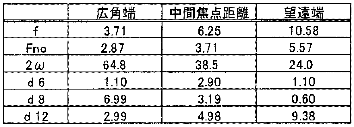


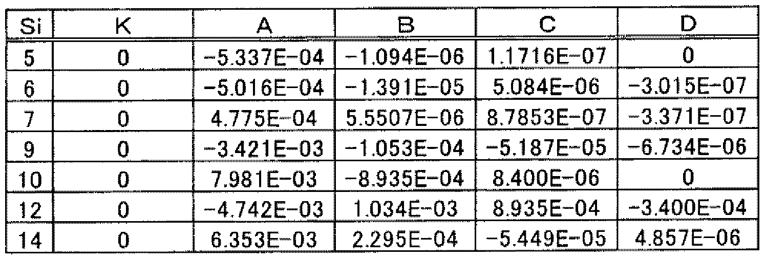


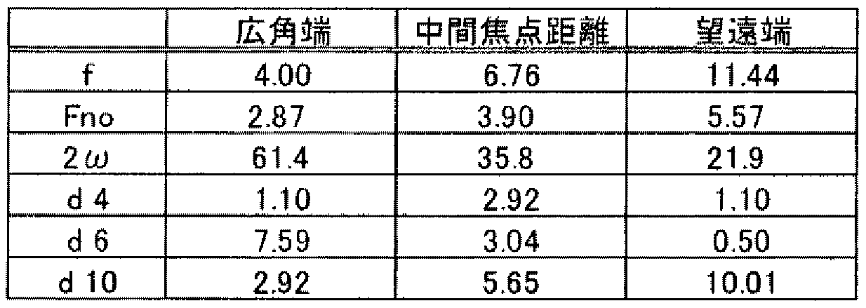


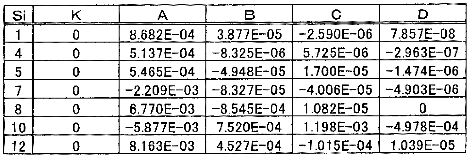


Claims
Priority Applications (3)
| Application Number | Priority Date | Filing Date | Title |
|---|---|---|---|
| US12/065,024 US7986467B2 (en) | 2006-06-28 | 2007-06-28 | Zoom lens and imaging apparatus |
| CN2007800011485A CN101356465B (zh) | 2006-06-28 | 2007-06-28 | 变焦透镜和成像装置 |
| EP07767820A EP2034346A4 (en) | 2006-06-28 | 2007-06-28 | ZOOMOBJECTIVE AND PICTURE DEVICE |
Applications Claiming Priority (4)
| Application Number | Priority Date | Filing Date | Title |
|---|---|---|---|
| JP2006-177855 | 2006-06-28 | ||
| JP2006177855 | 2006-06-28 | ||
| JP2006-253251 | 2006-09-19 | ||
| JP2006253251A JP4605475B2 (ja) | 2006-06-28 | 2006-09-19 | ズームレンズ及び撮像装置 |
Publications (1)
| Publication Number | Publication Date |
|---|---|
| WO2008001861A1 true WO2008001861A1 (en) | 2008-01-03 |
Family
ID=38845625
Family Applications (1)
| Application Number | Title | Priority Date | Filing Date |
|---|---|---|---|
| PCT/JP2007/063027 Ceased WO2008001861A1 (en) | 2006-06-28 | 2007-06-28 | Zoom lens and imaging device |
Country Status (7)
| Country | Link |
|---|---|
| US (1) | US7986467B2 (ja) |
| EP (1) | EP2034346A4 (ja) |
| JP (1) | JP4605475B2 (ja) |
| KR (1) | KR20090025183A (ja) |
| CN (1) | CN101356465B (ja) |
| TW (1) | TW200818878A (ja) |
| WO (1) | WO2008001861A1 (ja) |
Families Citing this family (24)
| Publication number | Priority date | Publication date | Assignee | Title |
|---|---|---|---|---|
| US20060197852A1 (en) * | 2005-03-01 | 2006-09-07 | Olympus Imaging Corp. | Zoom optical system and electronic imaging apparatus having the same |
| JP5252709B2 (ja) * | 2008-12-01 | 2013-07-31 | 株式会社オプトロジック | ズームレンズ |
| JP5334298B2 (ja) * | 2009-01-22 | 2013-11-06 | 株式会社オプトロジック | ズームレンズ |
| JP2010286614A (ja) * | 2009-06-10 | 2010-12-24 | Sony Corp | ズームレンズ及び撮像装置 |
| JP5531206B2 (ja) * | 2010-04-26 | 2014-06-25 | 株式会社オプトロジック | ズームレンズ |
| JP5282314B2 (ja) * | 2010-05-19 | 2013-09-04 | コニカミノルタ株式会社 | ズームレンズ及び撮像装置 |
| JP2012173435A (ja) * | 2011-02-18 | 2012-09-10 | Tamron Co Ltd | 固定焦点レンズ |
| US8711488B2 (en) | 2011-07-19 | 2014-04-29 | Optical Logic Inc. | Zoom lens |
| JP5845972B2 (ja) * | 2012-02-29 | 2016-01-20 | 株式会社ニコン | 変倍光学系、光学装置 |
| WO2013129487A1 (ja) | 2012-02-29 | 2013-09-06 | 株式会社ニコン | 変倍光学系、光学装置、変倍光学系の製造方法 |
| CN103487919A (zh) * | 2012-06-13 | 2014-01-01 | 华晶科技股份有限公司 | 摄像镜片组及其摄像装置 |
| JP6405629B2 (ja) * | 2013-12-26 | 2018-10-17 | 株式会社ニコン | 光学系、光学装置 |
| US9316810B2 (en) | 2014-03-07 | 2016-04-19 | Apple Inc. | Folded telephoto camera lens system |
| JP6425482B2 (ja) * | 2014-09-22 | 2018-11-21 | キヤノン株式会社 | ズームレンズおよびこれを用いた撮像装置 |
| CN105068228A (zh) * | 2015-07-31 | 2015-11-18 | 瑞声声学科技(苏州)有限公司 | 一种大相对孔径小型变焦距光学系统 |
| JP6532451B2 (ja) | 2016-12-27 | 2019-06-19 | キヤノン株式会社 | ズームレンズ及びそれを有する撮像装置 |
| KR102310641B1 (ko) * | 2017-07-23 | 2021-10-08 | 코어포토닉스 리미티드 | 큰 애퍼처를 갖는 컴팩터형 폴디드 렌즈 |
| TWI637207B (zh) | 2017-09-22 | 2018-10-01 | 大立光電股份有限公司 | 成像透鏡組、取像裝置及電子裝置 |
| JP6993251B2 (ja) * | 2018-02-01 | 2022-01-13 | リコーインダストリアルソリューションズ株式会社 | 投射光学系および画像表示装置 |
| CN110412716B (zh) * | 2018-04-27 | 2025-05-13 | 江西欧菲光学有限公司 | 潜望式镜头、成像模组和电子装置 |
| KR102867025B1 (ko) * | 2020-10-12 | 2025-10-02 | 삼성전기주식회사 | 카메라 모듈 |
| JP7583572B2 (ja) | 2020-10-16 | 2024-11-14 | キヤノン株式会社 | ズームレンズ、並びにそれを有する撮像装置及び撮像システム |
| CN112612125B (zh) * | 2020-12-31 | 2025-09-09 | 江西欧菲光学有限公司 | 变焦光学系统、变焦取像模组及电子设备 |
| US12192606B2 (en) | 2021-10-07 | 2025-01-07 | Samsung Electro-Mechanics Co., Ltd. | Imaging lens system and camera module |
Citations (10)
| Publication number | Priority date | Publication date | Assignee | Title |
|---|---|---|---|---|
| JPH11281889A (ja) * | 1998-03-26 | 1999-10-15 | Canon Inc | 変倍ファインダー |
| JP2000131610A (ja) | 1998-10-28 | 2000-05-12 | Sony Corp | ズームレンズ |
| JP2001091861A (ja) * | 1999-09-27 | 2001-04-06 | Ricoh Co Ltd | 実像式変倍ファインダ光学系 |
| JP2002072089A (ja) * | 2000-09-04 | 2002-03-12 | Minolta Co Ltd | 撮像装置 |
| JP2003315687A (ja) * | 2002-04-18 | 2003-11-06 | Pentax Corp | 接眼変倍光学系 |
| JP2004348082A (ja) * | 2003-05-26 | 2004-12-09 | Olympus Corp | 光路折り曲げ光学系 |
| JP2004354869A (ja) | 2003-05-30 | 2004-12-16 | Sony Corp | ズームレンズおよび撮像装置 |
| JP2005308963A (ja) * | 2004-04-20 | 2005-11-04 | Canon Inc | 変倍ファインダー |
| JP2006154481A (ja) * | 2004-11-30 | 2006-06-15 | Konica Minolta Opto Inc | 変倍光学系、撮像レンズ装置及びデジタル機器 |
| JP2006163075A (ja) * | 2004-12-08 | 2006-06-22 | Konica Minolta Opto Inc | 変倍光学系、撮像レンズ装置及びデジタル機器 |
Family Cites Families (17)
| Publication number | Priority date | Publication date | Assignee | Title |
|---|---|---|---|---|
| JP2596755B2 (ja) * | 1987-08-14 | 1997-04-02 | オリンパス光学工業株式会社 | 2焦点距離切り換え式レンズ系のフオーカシング方式 |
| JPH04223418A (ja) * | 1990-12-26 | 1992-08-13 | Olympus Optical Co Ltd | 全長の短いズームレンズ |
| JPH07174969A (ja) * | 1993-12-17 | 1995-07-14 | Minolta Co Ltd | 変倍ファインダー光学系 |
| JP3668365B2 (ja) * | 1997-10-14 | 2005-07-06 | オリンパス株式会社 | ズームレンズ |
| US7436599B2 (en) * | 2001-05-14 | 2008-10-14 | Olympus Corporation | Electronic image pickup system |
| JP4145066B2 (ja) * | 2002-04-09 | 2008-09-03 | オリンパス株式会社 | ズームレンズとそれを用いた電子撮像装置 |
| US7085070B2 (en) * | 2002-05-14 | 2006-08-01 | Olympus Corporation | Zoom lens and electronic imaging device having the same |
| JP2004037927A (ja) * | 2002-07-04 | 2004-02-05 | Minolta Co Ltd | 撮像装置 |
| JP4285957B2 (ja) * | 2002-08-29 | 2009-06-24 | オリンパス株式会社 | ズームレンズ及びそれを有する電子撮像装置 |
| JP4450600B2 (ja) * | 2003-03-10 | 2010-04-14 | 日本電産コパル株式会社 | ズームレンズ |
| JP3750672B2 (ja) * | 2003-05-20 | 2006-03-01 | コニカミノルタフォトイメージング株式会社 | 撮像レンズ装置 |
| JP4140011B2 (ja) * | 2004-01-28 | 2008-08-27 | ソニー株式会社 | ズームレンズ及び撮像装置 |
| JP2005266173A (ja) * | 2004-03-17 | 2005-09-29 | Sony Corp | ズームレンズ及び撮像装置 |
| JP2006064839A (ja) * | 2004-08-25 | 2006-03-09 | Konica Minolta Opto Inc | ズームレンズおよび撮像装置 |
| EP1637913B1 (en) * | 2004-09-16 | 2013-10-23 | Konica Minolta Opto, Inc. | Zoom lens and image pickup apparatus |
| JP2006098686A (ja) * | 2004-09-29 | 2006-04-13 | Olympus Corp | ズームレンズ及びそれを用いた電子撮像装置 |
| JP2007004020A (ja) * | 2005-06-27 | 2007-01-11 | Sony Corp | ズームレンズ及び撮像装置 |
-
2006
- 2006-09-19 JP JP2006253251A patent/JP4605475B2/ja not_active Expired - Fee Related
-
2007
- 2007-06-25 TW TW096122836A patent/TW200818878A/zh not_active IP Right Cessation
- 2007-06-28 CN CN2007800011485A patent/CN101356465B/zh not_active Expired - Fee Related
- 2007-06-28 WO PCT/JP2007/063027 patent/WO2008001861A1/ja not_active Ceased
- 2007-06-28 US US12/065,024 patent/US7986467B2/en not_active Expired - Fee Related
- 2007-06-28 EP EP07767820A patent/EP2034346A4/en not_active Withdrawn
- 2007-06-28 KR KR1020087004447A patent/KR20090025183A/ko not_active Ceased
Patent Citations (10)
| Publication number | Priority date | Publication date | Assignee | Title |
|---|---|---|---|---|
| JPH11281889A (ja) * | 1998-03-26 | 1999-10-15 | Canon Inc | 変倍ファインダー |
| JP2000131610A (ja) | 1998-10-28 | 2000-05-12 | Sony Corp | ズームレンズ |
| JP2001091861A (ja) * | 1999-09-27 | 2001-04-06 | Ricoh Co Ltd | 実像式変倍ファインダ光学系 |
| JP2002072089A (ja) * | 2000-09-04 | 2002-03-12 | Minolta Co Ltd | 撮像装置 |
| JP2003315687A (ja) * | 2002-04-18 | 2003-11-06 | Pentax Corp | 接眼変倍光学系 |
| JP2004348082A (ja) * | 2003-05-26 | 2004-12-09 | Olympus Corp | 光路折り曲げ光学系 |
| JP2004354869A (ja) | 2003-05-30 | 2004-12-16 | Sony Corp | ズームレンズおよび撮像装置 |
| JP2005308963A (ja) * | 2004-04-20 | 2005-11-04 | Canon Inc | 変倍ファインダー |
| JP2006154481A (ja) * | 2004-11-30 | 2006-06-15 | Konica Minolta Opto Inc | 変倍光学系、撮像レンズ装置及びデジタル機器 |
| JP2006163075A (ja) * | 2004-12-08 | 2006-06-22 | Konica Minolta Opto Inc | 変倍光学系、撮像レンズ装置及びデジタル機器 |
Non-Patent Citations (1)
| Title |
|---|
| See also references of EP2034346A4 |
Also Published As
| Publication number | Publication date |
|---|---|
| TWI341126B (ja) | 2011-04-21 |
| EP2034346A4 (en) | 2010-10-27 |
| KR20090025183A (ko) | 2009-03-10 |
| US7986467B2 (en) | 2011-07-26 |
| TW200818878A (en) | 2008-04-16 |
| JP4605475B2 (ja) | 2011-01-05 |
| JP2008033208A (ja) | 2008-02-14 |
| EP2034346A1 (en) | 2009-03-11 |
| CN101356465A (zh) | 2009-01-28 |
| CN101356465B (zh) | 2011-06-22 |
| US20100014169A1 (en) | 2010-01-21 |
Similar Documents
| Publication | Publication Date | Title |
|---|---|---|
| WO2008001861A1 (en) | Zoom lens and imaging device | |
| CN101183172B (zh) | 变焦透镜系统和利用该变焦透镜系统的电子图像拾取装置 | |
| US7952811B2 (en) | Zoom lens and image pickup device | |
| CN102819100B (zh) | 变焦镜头以及采用该变焦镜头的摄像装置 | |
| US7042652B2 (en) | Image-taking apparatus | |
| KR20150062803A (ko) | 줌 렌즈 및 이를 포함한 촬영 장치 | |
| CN100582857C (zh) | 变焦透镜及摄像装置 | |
| KR101932722B1 (ko) | 줌 렌즈 및 이를 포함한 촬영 장치 | |
| US20050200968A1 (en) | Image-taking apparatus | |
| CN201413424Y (zh) | 变焦透镜及摄像装置以及移动电话机 | |
| JP2013061476A (ja) | レンズ光学系及び撮像装置 | |
| JP2005215165A (ja) | ズームレンズ及び撮像装置 | |
| JP2005274662A (ja) | 接合レンズを有するズームレンズ | |
| JP2012042811A (ja) | ズームレンズ及び撮像装置 | |
| JP5703869B2 (ja) | ズームレンズ及び撮像装置 | |
| JP2010286614A (ja) | ズームレンズ及び撮像装置 | |
| JP2010256417A (ja) | ズームレンズ及び撮像装置 | |
| JP2005084285A (ja) | ズームレンズおよび撮像装置 | |
| JP2007155868A (ja) | 撮像レンズ及び撮像装置 | |
| US8031256B2 (en) | Zoom lens and image pickup device | |
| JP2006064961A (ja) | 撮像レンズ及び撮像装置 | |
| JP2012252278A (ja) | ズームレンズ及び撮像装置 | |
| JP5778491B2 (ja) | ズームレンズ及びそれを用いた撮像装置 | |
| JP2013007845A (ja) | ズームレンズ及び撮像装置 | |
| JP5626647B2 (ja) | ズームレンズおよび撮像装置 |
Legal Events
| Date | Code | Title | Description |
|---|---|---|---|
| WWE | Wipo information: entry into national phase |
Ref document number: 200780001148.5 Country of ref document: CN |
|
| WWE | Wipo information: entry into national phase |
Ref document number: 1020087004447 Country of ref document: KR Ref document number: 2007767820 Country of ref document: EP |
|
| 121 | Ep: the epo has been informed by wipo that ep was designated in this application |
Ref document number: 07767820 Country of ref document: EP Kind code of ref document: A1 |
|
| NENP | Non-entry into the national phase |
Ref country code: DE |
|
| NENP | Non-entry into the national phase |
Ref country code: RU |
|
| WWE | Wipo information: entry into national phase |
Ref document number: 12065024 Country of ref document: US |