WO2008044761A1 - Séparateur pour accumulateur secondaire à électrolyte non aqueux et séparateur à couches multiples pour accumulateur secondaire à électrolyte non aqueux - Google Patents
Séparateur pour accumulateur secondaire à électrolyte non aqueux et séparateur à couches multiples pour accumulateur secondaire à électrolyte non aqueux Download PDFInfo
- Publication number
- WO2008044761A1 WO2008044761A1 PCT/JP2007/069925 JP2007069925W WO2008044761A1 WO 2008044761 A1 WO2008044761 A1 WO 2008044761A1 JP 2007069925 W JP2007069925 W JP 2007069925W WO 2008044761 A1 WO2008044761 A1 WO 2008044761A1
- Authority
- WO
- WIPO (PCT)
- Prior art keywords
- separator
- secondary battery
- electrolyte secondary
- nonaqueous electrolyte
- less
- Prior art date
- Legal status (The legal status is an assumption and is not a legal conclusion. Google has not performed a legal analysis and makes no representation as to the accuracy of the status listed.)
- Ceased
Links
Classifications
-
- H—ELECTRICITY
- H01—ELECTRIC ELEMENTS
- H01M—PROCESSES OR MEANS, e.g. BATTERIES, FOR THE DIRECT CONVERSION OF CHEMICAL ENERGY INTO ELECTRICAL ENERGY
- H01M50/00—Constructional details or processes of manufacture of the non-active parts of electrochemical cells other than fuel cells, e.g. hybrid cells
- H01M50/40—Separators; Membranes; Diaphragms; Spacing elements inside cells
- H01M50/403—Manufacturing processes of separators, membranes or diaphragms
-
- H—ELECTRICITY
- H01—ELECTRIC ELEMENTS
- H01M—PROCESSES OR MEANS, e.g. BATTERIES, FOR THE DIRECT CONVERSION OF CHEMICAL ENERGY INTO ELECTRICAL ENERGY
- H01M50/00—Constructional details or processes of manufacture of the non-active parts of electrochemical cells other than fuel cells, e.g. hybrid cells
- H01M50/40—Separators; Membranes; Diaphragms; Spacing elements inside cells
- H01M50/409—Separators, membranes or diaphragms characterised by the material
- H01M50/411—Organic material
- H01M50/414—Synthetic resins, e.g. thermoplastics or thermosetting resins
- H01M50/417—Polyolefins
-
- H—ELECTRICITY
- H01—ELECTRIC ELEMENTS
- H01M—PROCESSES OR MEANS, e.g. BATTERIES, FOR THE DIRECT CONVERSION OF CHEMICAL ENERGY INTO ELECTRICAL ENERGY
- H01M10/00—Secondary cells; Manufacture thereof
- H01M10/05—Accumulators with non-aqueous electrolyte
-
- H—ELECTRICITY
- H01—ELECTRIC ELEMENTS
- H01M—PROCESSES OR MEANS, e.g. BATTERIES, FOR THE DIRECT CONVERSION OF CHEMICAL ENERGY INTO ELECTRICAL ENERGY
- H01M50/00—Constructional details or processes of manufacture of the non-active parts of electrochemical cells other than fuel cells, e.g. hybrid cells
- H01M50/40—Separators; Membranes; Diaphragms; Spacing elements inside cells
- H01M50/409—Separators, membranes or diaphragms characterised by the material
- H01M50/449—Separators, membranes or diaphragms characterised by the material having a layered structure
-
- H—ELECTRICITY
- H01—ELECTRIC ELEMENTS
- H01M—PROCESSES OR MEANS, e.g. BATTERIES, FOR THE DIRECT CONVERSION OF CHEMICAL ENERGY INTO ELECTRICAL ENERGY
- H01M50/00—Constructional details or processes of manufacture of the non-active parts of electrochemical cells other than fuel cells, e.g. hybrid cells
- H01M50/40—Separators; Membranes; Diaphragms; Spacing elements inside cells
- H01M50/489—Separators, membranes, diaphragms or spacing elements inside the cells, characterised by their physical properties, e.g. swelling degree, hydrophilicity or shut down properties
-
- H—ELECTRICITY
- H01—ELECTRIC ELEMENTS
- H01M—PROCESSES OR MEANS, e.g. BATTERIES, FOR THE DIRECT CONVERSION OF CHEMICAL ENERGY INTO ELECTRICAL ENERGY
- H01M50/00—Constructional details or processes of manufacture of the non-active parts of electrochemical cells other than fuel cells, e.g. hybrid cells
- H01M50/40—Separators; Membranes; Diaphragms; Spacing elements inside cells
- H01M50/489—Separators, membranes, diaphragms or spacing elements inside the cells, characterised by their physical properties, e.g. swelling degree, hydrophilicity or shut down properties
- H01M50/491—Porosity
-
- Y—GENERAL TAGGING OF NEW TECHNOLOGICAL DEVELOPMENTS; GENERAL TAGGING OF CROSS-SECTIONAL TECHNOLOGIES SPANNING OVER SEVERAL SECTIONS OF THE IPC; TECHNICAL SUBJECTS COVERED BY FORMER USPC CROSS-REFERENCE ART COLLECTIONS [XRACs] AND DIGESTS
- Y02—TECHNOLOGIES OR APPLICATIONS FOR MITIGATION OR ADAPTATION AGAINST CLIMATE CHANGE
- Y02E—REDUCTION OF GREENHOUSE GAS [GHG] EMISSIONS, RELATED TO ENERGY GENERATION, TRANSMISSION OR DISTRIBUTION
- Y02E60/00—Enabling technologies; Technologies with a potential or indirect contribution to GHG emissions mitigation
- Y02E60/10—Energy storage using batteries
-
- Y—GENERAL TAGGING OF NEW TECHNOLOGICAL DEVELOPMENTS; GENERAL TAGGING OF CROSS-SECTIONAL TECHNOLOGIES SPANNING OVER SEVERAL SECTIONS OF THE IPC; TECHNICAL SUBJECTS COVERED BY FORMER USPC CROSS-REFERENCE ART COLLECTIONS [XRACs] AND DIGESTS
- Y02—TECHNOLOGIES OR APPLICATIONS FOR MITIGATION OR ADAPTATION AGAINST CLIMATE CHANGE
- Y02P—CLIMATE CHANGE MITIGATION TECHNOLOGIES IN THE PRODUCTION OR PROCESSING OF GOODS
- Y02P70/00—Climate change mitigation technologies in the production process for final industrial or consumer products
- Y02P70/50—Manufacturing or production processes characterised by the final manufactured product
Definitions
- the present invention relates to a separator for a non-aqueous electrolyte secondary battery treated with fluorine gas (fluorine treatment), and a separator for a non-aqueous electrolyte secondary battery using the same.
- a separator for a non-aqueous electrolyte secondary battery such as a lithium ion secondary battery requires electrical insulation to separate the positive electrode and the negative electrode, and chemical and electrochemical stability with respect to the non-aqueous electrolyte.
- a microporous film made of a resin such as polyolefin, a nonwoven fabric or the like is generally used.
- a resin such as polyolefin, a nonwoven fabric or the like
- shutdown characteristics are also essential.
- low-melting polyolefin resins such as polyethylene and polypropylene are often used as separator raw materials, and insulation and mechanical strength depend on the resin's molecular weight, porosity, and pore distribution. Has been held.
- polyolefin-based materials are generally hydrophobic and have insufficient electrolyte retention. If the electrolyte is not sufficiently retained, the electrolyte will be extruded due to the shrinkage and expansion effects of the negative electrode during charge and discharge, causing the electrolyte to wither, resulting in reduced capacity and battery deterioration. There were cases where they were connected. For this reason, sulfonation treatment, corona discharge method, plasma discharge method, ultraviolet irradiation method, etc. have been proposed as means for hydrophilizing polyolefin materials to improve their affinity with electrolytes. There are problems such as processing cost and sustainability of the effect, and V, the means of deviation has reached a sufficient solution.
- Patent Document 1 Japanese Patent Application Laid-Open No. 6-116436
- Patent Document 2 Japanese Patent No. 3521523
- the present invention relates to a separator for a non-aqueous electrolyte secondary battery that is used for a lithium ion secondary battery or the like that improves the electrolyte solution retainability by improving the electrolyte solution affinity of the separator and that maintains the shutdown characteristics. And to provide a multi-layer separator for a non-aqueous electrolyte secondary battery.
- the separator for a non-aqueous electrolyte secondary battery according to the present invention is obtained by subjecting a polyolefin resin to a fluorine treatment, and has a contact angle force with a non-aqueous solvent electrolyte of 0 ° or less and a shutdown temperature. 170 ° C or less.
- the multi-layer separator for a non-aqueous electrolyte secondary battery of the present invention is composed of a plurality of layers, and at least one of the plurality of layers is composed of the above-described separator for a non-aqueous electrolyte secondary battery.
- an electrolyte-compatible functional group is introduced into at least a part of the surface of the polyolefin resin, the contact angle force with the non-aqueous solvent electrolyte is 0 ° or less, and the shutdown temperature is 170 °.
- the gist of the separator is a non-aqueous electrolyte secondary battery characterized by being C or less.
- the non-aqueous electrolyte secondary battery separator and the non-aqueous electrolyte secondary battery multi-layer separator of the present invention have remarkably improved electrolyte retention while maintaining shutdown performance.
- a separator for a non-aqueous electrolyte secondary battery (sometimes simply referred to as a separator) will be described.
- functional groups having an affinity for an electrolyte such as a carbonyl group and a carboxyl group are introduced into at least a part of the separator surface before the treatment by fluorine treatment.
- the fluorine treatment is performed under specific conditions.
- the fluorine treatment in the present invention means a slight treatment for the whole or a part of the separator surface where the partial pressure of fluorine gas is as small as possible. Specifically, ⁇ 50 ° C. to 100 ° C. A partial pressure generated by a fluorine gas generator (not shown) at a temperature of 1 to;! OOPa fluorine gas and oxygen gas are mixed, and the whole or part of the separator surface is brought into contact with the mixed gas. is there.
- the fluorine gas partial pressure is within the above range, the shutdown property and the electrolyte retention property are maintained well. If the fluorine gas partial pressure is less than Pa, no functional group having an electrolyte compatibility is introduced. If the fluorine gas partial pressure is greater than lOOPa, a functional group having an electrolyte compatibility is introduced, but at the same time, Since the molecular chain cross-linking reaction proceeds, the fluidity of the molecules deteriorates, resulting in an increase in shutdown temperature. In addition, the heat of reaction during the treatment increases, and the separator surface partially melts to block the pores in the separator, resulting in loss of shutdown performance. Furthermore, a preferable fluorine partial pressure is in the range of 1 to 50 Pa.
- the partial pressure of the oxygen gas to be mixed is not particularly limited, but the range of lkPa to 300 kPa is more preferably 50 kPa to 200 kPa.
- the oxygen gas to be mixed may be appropriately diluted with an inert gas such as nitrogen gas or helium gas.
- a functional group having an affinity for an electrolyte such as a carboxyl group or a carboxyl group is introduced into at least a part of the surface.
- the introduction of functional groups with affinity for electrolyte can be confirmed by known analytical methods such as X-ray photoelectron spectroscopy (XPS) and time-of-flight secondary ion mass spectrometry (TOF—SIMS).
- the contact angle with the non-aqueous solvent electrolyte must be 40 ° or less. If it exceeds 40 °, the electrolyte retainability is poor and sufficient battery performance cannot be obtained. Preferably it is 30 ° or less, more preferably 20 ° or less. Also shut The down temperature must be 170 ° C or less. The temperature is preferably 160 ° C or lower, more preferably 155 ° C or lower. If the temperature exceeds 170 ° C, the shutdown will be delayed, so it may not be possible to sufficiently prevent a short circuit of the battery.
- the separator of the present embodiment was measured by a nitrogen adsorption method using a specific surface area measurement device from the viewpoint that when the fluorine treatment was performed, an appropriate amount of cross-linking reaction was obtained and good shutdown characteristics were easily obtained.
- Specific surface area force lm 2 / g or more When the fluorine treatment is applied, it is possible to uniformly treat the wall surface of the pores of the separator because the specific surface area is 100 m 2 / g or less. It is preferable that More preferred specific surface area 10 m '/ g ⁇ 80m 2 / g , more preferably a specific surface area is 15m 2 / g ⁇ 60m 2 / g.
- the separator has sufficient insulation, and the preferred film thickness is 1 m or more. It is preferable that the length is 100 m or less because it is advantageous in terms of conversion, and s is preferably 2 ⁇ m to 50 ⁇ m, and more preferably 5 ⁇ m to 40 ⁇ m.
- the porosity is preferably 25% or more from the viewpoint of permeability, and the porosity is preferably 90% or less from the viewpoint of reliability with little possibility of self-discharge. Preferably it is below. A more preferable porosity is 30% to 70%, and a further preferable porosity is 35% to 60%.
- the air permeability measured by a Gurley type air permeability meter in accordance with JIS P-8117 is 10 seconds because of less self-discharge.
- the above is preferably 1000 seconds or less from the viewpoint of obtaining favorable charge / discharge characteristics.
- a more preferable air permeability is 50 seconds to 700 seconds, and an even more preferable air permeability is 80 seconds to 500 seconds.
- the separator of this embodiment it is possible to uniformly fluorinate the wall surface of the pore portion of the separator, and from the point of excellent ion permeability, measurement is performed by a mercury intrusion method using a mercury porosimeter.
- the hole diameter (porosity mode diameter) should be 0 ⁇ 05 m or more.
- Is preferably 5 in or less.
- a more preferable diameter is 0. OZ ⁇ m-l ⁇ m, and a more preferable diameter is 0.1 m to 0.7. ⁇ m.
- the strength is preferably 2N or more.
- the upper limit of the puncture strength is not particularly limited, but is preferably 20 N or less from the viewpoint of reducing width shrinkage due to orientation relaxation during heating. More preferable puncture strength is 3N to 10N, and further preferable puncture strength is 4 to 8 ⁇ .
- the piercing strength is obtained by performing a piercing test using a KES-G5 handy compression tester manufactured by Kato Tech Co., Ltd. under the conditions of a radius of curvature of the needle tip of 0.5 mm and a piercing speed of 2 mm / Sec. It is the maximum piercing load (N).
- the heat shrinkage rate is 30% or less from the viewpoint of suppressing short circuit between electrodes, more preferably 20% or less, and further 10%.
- a microporous film made of a polyolefin resin such as polyethylene or polypropylene is used as the separator as described above.
- the method for producing such a microporous membrane is not particularly limited. A manufacturing method is mentioned. More specifically, the polyolefin powder is mixed with a plasticizer, melt-extruded into a sheet, and then the so-called wet method in which the plasticizer is extracted with a solvent to make it microporous, or the polyolefin is mixed with the plasticizer.
- the so-called dry method which is melt-extruded into a film by the T-die method or tubular method, heat-treated at a temperature near the crystallization temperature of polyolefin, and then stretched uniaxially or biaxially to make it microporous.
- inorganic particles are mixed with polyolefin, melt-extruded into a film by a T-dy method, and then stretched uniaxially or biaxially to exfoliate the interface between the polyolefin resin and inorganic particles to make it microporous. The method of making it use is also used.
- a method of co-extrusion with a plurality of extruders to form a multilayer or any method is used to stack a plurality of single-layer microporous films formed, and a heated press roll
- a method of multilayering by heat bonding between the layers or the like can also be taken.
- high-pressure low-density polyethylene linear low-density polyethylene, single-stage polymerization or high-stage polymerization of high-density polyethylene is preferably used.
- density of high-density polyethylene since high strength is easy to improve the electrolytic solution affinity by the resulting Ya immediately fluorine treatment, it is preferably set to 0. 941g / cm 3 ⁇ 0. 959g / cm 3 .
- the catalyst for linear low-density polyethylene and high-density polyethylene is not particularly limited, such as general titanium-based, chromium-based, and meta-octane-based catalysts.
- Polypropylene may have any structure such as isotactic, syndiotactic and atactic. Further, a random copolymer or a block copolymer may be used. Of course, these resins may be mixed with each other as long as the effect of the separator of the present embodiment is not impaired. An inorganic filler such as a heat stabilizer may be added. In addition, since it is easy to obtain good shutdown characteristics and good electrolyte compatibility, polyolefins having an alkyl side chain (for example, 1-butene, 4-methyl-1 pentene, 1-hexene, 1? Polyethylene copolymers containing monomers, polypropylene, polyethylene obtained with chromium-based catalysts, etc.) may be mixed.
- alkyl side chain for example, 1-butene, 4-methyl-1 pentene, 1-hexene, 1?
- the preferred temperature when contacting with the fluorine gas is in the range of 1-50 ° C to 100 ° C.
- the temperature is lower than 50 ° C, introduction of a functional group having an electrolyte solution affinity is insufficient, which is not preferable from the viewpoint of the electrolyte solution affinity. Further, if the temperature exceeds 100 ° C, the separator is deformed or burned by heat due to excessive reaction heat with fluorine gas, which is not preferable. More preferably, it is 50 ° C or lower.
- the volume ratio of the fluorine gas to the oxygen gas should be a condition of less than 0.01, preferably S, more preferably less than 0.001.
- a good shutdown property can be secured.
- the volume ratio is 0.01 or more, the cross-linking reaction of the polymer chain proceeds or excessive reaction heat is generated, resulting in a fine reaction in the separator. Since the hole is blocked, the shutdown performance may be impaired.
- the separator for a nonaqueous electrolyte secondary battery of the present embodiment the electrolyte retention is remarkably improved while maintaining the shutdown performance.
- the same effect can be achieved in the non-aqueous electrolyte secondary battery multi-layer separator having at least one non-aqueous electrolyte secondary battery separator of the present embodiment.
- a separator for a nonaqueous electrolyte secondary battery and a nonaqueous electrolyte secondary battery according to the present invention The multi-layer separator for use will be described using examples. First, each example and each comparative example will be described, and then the measurement method and evaluation method, and the measurement and evaluation results will be described.
- a polyethylene microporous membrane with a thickness of 20 am (trade name “Hypore” manufactured by Asahi Kasei Chemicals Co., Ltd.) is placed in a stainless steel reaction vessel and evacuated, followed by fluorine treatment under the conditions shown in Table 1 below. Samples according to Examples 1 to 7 were obtained.
- Comparative Example 1 a polyethylene porous membrane not subjected to fluorine treatment, and in Comparative Examples 2 to 5, fluorine treatment was performed under the conditions shown in Table 1 below, and samples of Comparative Examples 1 to 5 were obtained.
- FIG. 1 ⁇ shows a schematic diagram of the shutdown temperature evaluation test equipment.
- 1 is a microporous membrane (a sample of a separator for a nonaqueous electrolyte secondary battery according to an embodiment of the present invention or a sample according to a comparative example), and 2 mm and 2 mm are nickel foils having a thickness of lO ⁇ m, 3 mm and 3 mm Is a glass plate with a width of 25 mm, a length of 76 mm and a thickness of 1.4 mm.
- 4 is an electrical resistance measuring device (LCR meter “AG-4431” (registered trademark) manufactured by Ando Electric Co., Ltd.), which is connected to nickel foils 2A and 2B.
- 5 is a thermocouple connected to thermometer 6.
- a data collector 7 is connected to the electric resistance device 4 and the thermometer 6. 8 is an oven that heats the microporous membrane.
- the microporous membrane 1 is overlaid on the nickel foil 2A, and the “Teflon (registered trademark)” tape (the hatched portion in the figure) is vertically arranged. Secure to nickel foil 2A.
- "Teflon (registered trademark)” tape pasted on the nickel foil 2B, and a 15mm x 10mm window part is placed on the central part 2B of the foil 2B.
- Microporous membrane 1 is sandwiched between nickel foil 2A and nickel foil 2B, and two nickel foils are attached by glass plates 3A and 3B from both sides. Scissors. At this time, the window portion of the nickel foil 2B and the microporous membrane 1 come to face each other.
- the two glass plates are fixed by pinching with a commercially available double clip (trade name “: BINDER CLIPS No. 107N” manufactured by Lion Corporation).
- the thermocouple 5 is fixed to the glass plate with “Teflon” tape. Temperature and electrical resistance are continuously measured with such an apparatus.
- the temperature is raised from 25 ° C to 200 ° C at a rate of 2 ° C / min, and the electrical resistance is measured at 1 kHz AC.
- the shutdown temperature was defined as the temperature at which the electrical resistance of the microporous membrane reached 10 3 ⁇ .
- Example 1 1 120 20 40 148 Passed Example 2 20 120 20 26 155 Passed Example 3 60 120 20 14 162 Passed Example 4 100 120 20 10 165 Passed Example 5 20 120-50 32 150 Passed Example 6 20 120 100 6 170 Pass Example 7 20 100 20 22 142 Pass Comparative Example 1 ⁇ ⁇ ⁇ 71 140 Fail Comparative Example 2 0.5 120 20 41 147 Fail Comparative Example 3 200 120 20 8 171 Fail Comparative Example 4 20 120- 70 71 148 Fail Comparative example 5 20 120 135 6 195 Fail
- the specific surface area, porosity, air permeability, hole diameter, puncture strength, and heat shrinkage rate of the separator for the nonaqueous electrolyte secondary battery of Example 7 were measured.
- the polyethylene porous membrane used for the separator for the nonaqueous electrolyte secondary battery of Example 7 has a density of 0.95 g / cm 3 .
- the specific surface area measuring device (ASAP2400, manufactured by Shimadzu Corporation) was used for measurement by the nitrogen adsorption method.
- the sample was cut into strips, folded about 0.2 g into the cell, collected in the cell, and measured after degassing at room temperature for about 15 hours in the sample pretreatment section of the instrument.
- the specific surface area was determined by the BET method, and a measurement result of 36 m 2 / g was obtained.
- the Qigong rate was calculated to be 41%.
- the mode diameter was defined as the hole diameter.
- the pore diameter was 0.08 m.
- a piercing test was conducted with a needle tip curvature radius of 0.5 mm and a piercing speed of 2 mm / SeC. It was measured.
- the puncture strength was 4.5N.
- MD120mm XTD120mm square sample samples were cut from the microporous membrane and marked with oil-based pens at three TDlOOm m intervals.
- the microporous membrane was sandwiched between A4 size, 64 g / m2 basis weight, and 0.09 mm paper thickness (manufactured by KOKUYO S & T), and the sides of the copy paper were stapled. It was placed horizontally in an oven at 100 ° C and left for 1 hour. Thereafter, it was air-cooled, and the TD length (mm) between the above-mentioned marks was measured.
- the shrinkage ratio was calculated from the average value of the three locations and the following formula. The result was 1% or less.
- the multi-layer separator for a non-aqueous electrolyte secondary battery according to the present invention is a separator having improved shutdown characteristics, wettability of electrolyte solution and liquid retention, and a layer that causes shutdown and a layer that exhibits liquid retention. It is compatible with multiple layers that do not consist of a single separator. I have verified whether it can be done!
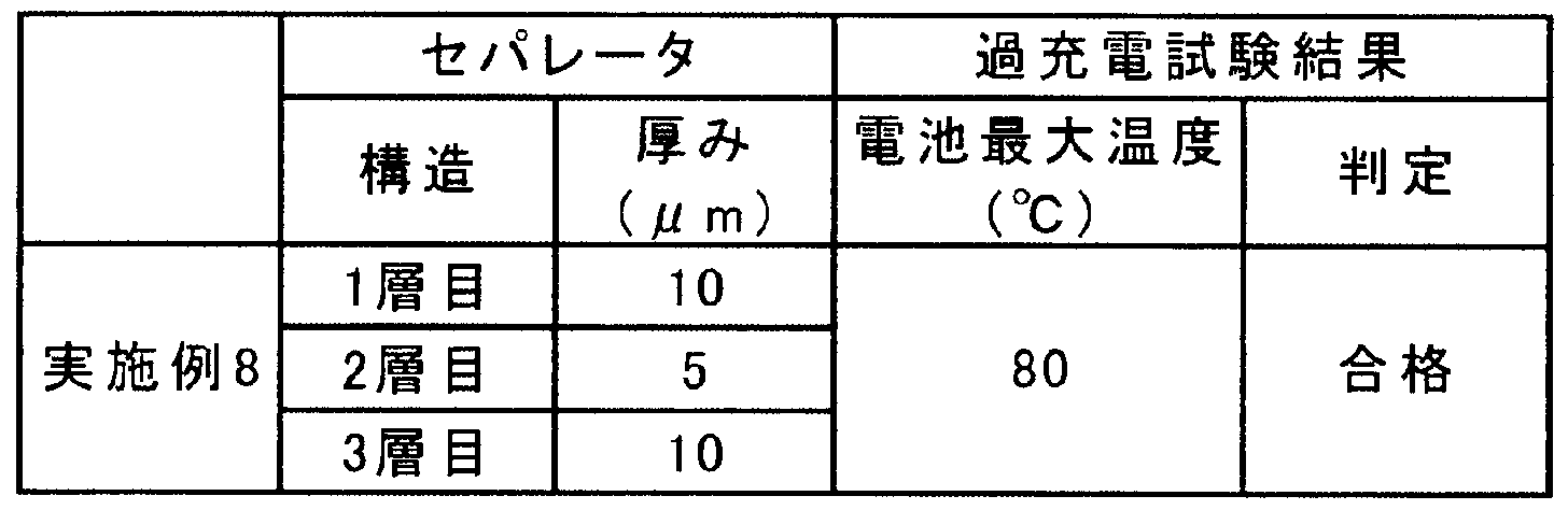
- a multilayer separator for a non-aqueous electrolyte secondary battery was produced as follows. A single polyethylene porous membrane with a thickness of 5 m is sandwiched between two polyethylene porous membranes with a thickness of 10 m that have been subjected to fluorine treatment. They were passed through and thermally bonded to obtain a separator having a three-layer structure. Here, this separator was measured and evaluated in the same manner as in Examples 1 to 6 described above. The results are shown together with Table 1 above!
- the multi-layer separator for a non-aqueous electrolyte secondary battery produced as described above was placed between the positive electrode and the negative electrode to produce a lithium ion secondary battery.
- LiCoO 95wt%, acetylene black 2wt% and PVDF 3wt% were mixed thoroughly and molded into 40mm x 40mm.
- Lithium metal was used for the negative electrode, and a mixed solvent (3: 7) of ethylene carbonate and jetyl carbonate containing lmol / 1 lithium hexafluorophosphate was used for the electrolyte.
- the lithium ion secondary battery according to the example was manufactured.
- the lithium ion secondary battery manufactured as described above is fully charged with a constant voltage charge of 4.2V (0.2 CA limit current), and then reaches a voltage of 2.7V with a constant current of 0.2 CA. Discharged. Next, it was connected to a stabilized power supply with an output voltage of 10V or more, and charged for 1.25 hours at 2CA current. At this time, if the safety device in the battery was activated, it was terminated at that time.
- the test environment temperature was 20 ⁇ 5 ° C, and the acceptance criteria were that the battery did not rupture or ignite. Moreover, even if it passed, it measured to the maximum temperature of the battery. Table 2 below shows the results of this overcharge test.
- Example 8 the liquid wettability was maintained, and the battery temperature at the time of overcharging was about 80 ° C. at the maximum.
- the overcharge current was suppressed at a relatively low temperature, and the increase in battery temperature was suppressed. This is because the liquid is held by 10 m separators on both outer sides of the three layers in contact with the positive electrode and the negative electrode, the reaction area increases, and the apparent overcharge current that contributes to the reaction is higher than that of separator batteries that cannot be held. The temperature is lowered and the exothermic reaction due to the growth of dendrites is suppressed if the deposition of metallic lithium.
- the electrolyte decomposes on the positive electrode to generate oxygen gas, and the exothermic reaction with LiC and metallic lithium occurs at the three-layer interface between the solid phase on the negative electrode surface, the electrolyte phase, and the spatial gas phase. Suppressed by the amount of liquid phase
- the present invention can be modified in design without departing from the scope of the claims, and is not limited to the above-described embodiments and examples.
- the separator of Example 8 an example of a porous film composed of a plurality of layers has been presented.
- the present invention is not limited to this example. The same effect can be obtained even in the case of separators that are combined or overlapped.
- a separator having both good electrolyte solution retention and appropriate shutdown properties can be obtained, which is suitable as a separator for a nonaqueous electrolyte secondary battery.
- FIG. 1 (a) is a schematic diagram showing a measurement apparatus for shutdown characteristics in the present invention, and (b) is (a).
- FIG. 6 is a plan view showing one of the nickel foils at, and (c) is a plan view showing the other of the nickel foils at ⁇ .
Landscapes
- Chemical & Material Sciences (AREA)
- Chemical Kinetics & Catalysis (AREA)
- Electrochemistry (AREA)
- General Chemical & Material Sciences (AREA)
- Engineering & Computer Science (AREA)
- Manufacturing & Machinery (AREA)
- Cell Separators (AREA)
- Secondary Cells (AREA)
- Manufacture Of Porous Articles, And Recovery And Treatment Of Waste Products (AREA)
Description
Claims
Priority Applications (5)
| Application Number | Priority Date | Filing Date | Title |
|---|---|---|---|
| EP07829661A EP2079119B1 (en) | 2006-10-13 | 2007-10-12 | Process for manufacturing a separator for a nonaqueous electrolyte secondary battery |
| JP2008538764A JPWO2008044761A1 (ja) | 2006-10-13 | 2007-10-12 | 非水電解質二次電池用セパレータ、及び、非水電解質二次電池用複数層セパレータ |
| US12/445,226 US20100009249A1 (en) | 2006-10-13 | 2007-10-12 | Separator for nonaqueous electrolyte secondary battery and multilayer separator for nonaqueous electrolyte secondary battery |
| KR1020097007244A KR101313458B1 (ko) | 2006-10-13 | 2007-10-12 | 비수전해질 이차전지용 세퍼레이터, 및 비수전해질 이차전지용 복수층 세퍼레이터 |
| CN2007800382502A CN101663778B (zh) | 2006-10-13 | 2007-10-12 | 非水电解质二次电池用隔板及非水电解质二次电池用多层隔板 |
Applications Claiming Priority (2)
| Application Number | Priority Date | Filing Date | Title |
|---|---|---|---|
| JP2006280212 | 2006-10-13 | ||
| JP2006-280212 | 2006-10-13 |
Publications (1)
| Publication Number | Publication Date |
|---|---|
| WO2008044761A1 true WO2008044761A1 (fr) | 2008-04-17 |
Family
ID=39282948
Family Applications (1)
| Application Number | Title | Priority Date | Filing Date |
|---|---|---|---|
| PCT/JP2007/069925 Ceased WO2008044761A1 (fr) | 2006-10-13 | 2007-10-12 | Séparateur pour accumulateur secondaire à électrolyte non aqueux et séparateur à couches multiples pour accumulateur secondaire à électrolyte non aqueux |
Country Status (6)
| Country | Link |
|---|---|
| US (1) | US20100009249A1 (ja) |
| EP (1) | EP2079119B1 (ja) |
| JP (1) | JPWO2008044761A1 (ja) |
| KR (1) | KR101313458B1 (ja) |
| CN (1) | CN101663778B (ja) |
| WO (1) | WO2008044761A1 (ja) |
Cited By (6)
| Publication number | Priority date | Publication date | Assignee | Title |
|---|---|---|---|---|
| JP2011165660A (ja) * | 2010-01-13 | 2011-08-25 | Sony Corp | セパレータおよび非水電解質電池 |
| JP2014107061A (ja) * | 2012-11-26 | 2014-06-09 | Toshiba Corp | 非水電解質電池 |
| DE102016114791A1 (de) | 2015-09-07 | 2017-03-09 | Toyota Jidosha Kabushiki Kaisha | Sekundärbatterie mit nicht-wässrigem Elektrolyt |
| JPWO2016157736A1 (ja) * | 2015-03-31 | 2018-01-25 | 三洋電機株式会社 | 非水電解質二次電池 |
| JP2019503571A (ja) * | 2016-05-30 | 2019-02-07 | エルジー・ケム・リミテッド | リチウム二次電池用分離膜及びこれを含むリチウム二次電池 |
| WO2025041623A1 (ja) * | 2023-08-23 | 2025-02-27 | 東レ株式会社 | 親水性多孔質フィルムおよびその製造方法 |
Families Citing this family (5)
| Publication number | Priority date | Publication date | Assignee | Title |
|---|---|---|---|---|
| US9083034B2 (en) * | 2013-03-15 | 2015-07-14 | Ford Global Technologies, Llc | Treated battery separator |
| KR20160139720A (ko) | 2015-05-28 | 2016-12-07 | (주)다위월드 | 광학 인식 기반의 시스템 매트 및 시스템 매트를 위한 광학 인식 장치 및 광학 인식 기반의 시스템 매트 제조 방법 |
| WO2017209495A1 (ko) * | 2016-05-30 | 2017-12-07 | 주식회사 엘지화학 | 리튬 이차전지용 분리막 및 이를 포함하는 리튬 이차전지 |
| CN106972139B (zh) * | 2017-03-10 | 2023-05-30 | 深圳中兴新材技术股份有限公司 | 一种聚烯烃微孔膜亲水性改性的方法及装置 |
| CN115799756A (zh) * | 2022-12-05 | 2023-03-14 | 湖南东舟能源有限公司 | 一种聚烯烃隔膜及其改性方法 |
Citations (10)
| Publication number | Priority date | Publication date | Assignee | Title |
|---|---|---|---|---|
| JPH06116436A (ja) | 1992-10-02 | 1994-04-26 | Mitsubishi Kasei Corp | 多孔質高分子膜の処理方法 |
| JPH09220453A (ja) | 1996-02-16 | 1997-08-26 | Asahi Chem Ind Co Ltd | 電池セパレーターに適した微多孔膜 |
| JPH11322989A (ja) | 1998-05-19 | 1999-11-26 | Asahi Chem Ind Co Ltd | ポリオレフィン製の電池セパレーター用微多孔膜 |
| JP2000173665A (ja) * | 1998-12-10 | 2000-06-23 | Mitsubishi Chemicals Corp | リチウム二次電池 |
| JP3235669B2 (ja) | 1991-12-20 | 2001-12-04 | セルガード・インコーポレーテッド | 電池用セパレータおよびその製造方法 |
| JP3258737B2 (ja) | 1993-01-19 | 2002-02-18 | 旭化成株式会社 | ポリエチレン微多孔性隔膜 |
| JP2002226639A (ja) * | 2001-01-31 | 2002-08-14 | Asahi Kasei Corp | 微多孔膜およびリチウム電池用セパレータ |
| JP2002343326A (ja) * | 2001-05-16 | 2002-11-29 | Asahi Kasei Corp | 電池セパレータ |
| JP3521523B2 (ja) | 1994-02-14 | 2004-04-19 | 三菱化学株式会社 | バッテリーセパレーター及びそれを用いた電池 |
| JP2005317217A (ja) * | 2004-04-26 | 2005-11-10 | Daiwabo Co Ltd | 有機電解液電池用セパレータ及びその製造方法 |
Family Cites Families (6)
| Publication number | Priority date | Publication date | Assignee | Title |
|---|---|---|---|---|
| JPS6119056A (ja) * | 1984-07-05 | 1986-01-27 | Fuji Elelctrochem Co Ltd | 電池用セパレ−タ |
| US5281491A (en) * | 1991-12-20 | 1994-01-25 | W. R. Grace & Co. | Battery separator |
| JP3482606B2 (ja) * | 1994-08-11 | 2003-12-22 | 日本電池株式会社 | 密閉形アルカリ蓄電池 |
| EP0743690A1 (en) * | 1995-05-17 | 1996-11-20 | Mitsubishi Chemical Corporation | Battery separator and method for its production |
| DE69939253D1 (de) * | 1998-12-02 | 2008-09-18 | Lg Chemical Ltd | Verfahren zur veränderung von polymeroberflächen zur besseren benetzbarkeit |
| US20070238017A1 (en) * | 2006-04-07 | 2007-10-11 | Celgard Llc | Multilayer separator exhibiting improved strength and stability |
-
2007
- 2007-10-12 EP EP07829661A patent/EP2079119B1/en not_active Not-in-force
- 2007-10-12 KR KR1020097007244A patent/KR101313458B1/ko not_active Expired - Fee Related
- 2007-10-12 JP JP2008538764A patent/JPWO2008044761A1/ja active Pending
- 2007-10-12 WO PCT/JP2007/069925 patent/WO2008044761A1/ja not_active Ceased
- 2007-10-12 US US12/445,226 patent/US20100009249A1/en not_active Abandoned
- 2007-10-12 CN CN2007800382502A patent/CN101663778B/zh not_active Expired - Fee Related
Patent Citations (10)
| Publication number | Priority date | Publication date | Assignee | Title |
|---|---|---|---|---|
| JP3235669B2 (ja) | 1991-12-20 | 2001-12-04 | セルガード・インコーポレーテッド | 電池用セパレータおよびその製造方法 |
| JPH06116436A (ja) | 1992-10-02 | 1994-04-26 | Mitsubishi Kasei Corp | 多孔質高分子膜の処理方法 |
| JP3258737B2 (ja) | 1993-01-19 | 2002-02-18 | 旭化成株式会社 | ポリエチレン微多孔性隔膜 |
| JP3521523B2 (ja) | 1994-02-14 | 2004-04-19 | 三菱化学株式会社 | バッテリーセパレーター及びそれを用いた電池 |
| JPH09220453A (ja) | 1996-02-16 | 1997-08-26 | Asahi Chem Ind Co Ltd | 電池セパレーターに適した微多孔膜 |
| JPH11322989A (ja) | 1998-05-19 | 1999-11-26 | Asahi Chem Ind Co Ltd | ポリオレフィン製の電池セパレーター用微多孔膜 |
| JP2000173665A (ja) * | 1998-12-10 | 2000-06-23 | Mitsubishi Chemicals Corp | リチウム二次電池 |
| JP2002226639A (ja) * | 2001-01-31 | 2002-08-14 | Asahi Kasei Corp | 微多孔膜およびリチウム電池用セパレータ |
| JP2002343326A (ja) * | 2001-05-16 | 2002-11-29 | Asahi Kasei Corp | 電池セパレータ |
| JP2005317217A (ja) * | 2004-04-26 | 2005-11-10 | Daiwabo Co Ltd | 有機電解液電池用セパレータ及びその製造方法 |
Non-Patent Citations (1)
| Title |
|---|
| See also references of EP2079119A4 |
Cited By (12)
| Publication number | Priority date | Publication date | Assignee | Title |
|---|---|---|---|---|
| JP2011165660A (ja) * | 2010-01-13 | 2011-08-25 | Sony Corp | セパレータおよび非水電解質電池 |
| JP2015099801A (ja) * | 2010-01-13 | 2015-05-28 | ソニー株式会社 | 非水電解質電池用セパレータおよび非水電解質電池 |
| US9786888B2 (en) | 2010-01-13 | 2017-10-10 | Sony Corporation | Separator and nonaqueous electrolyte battery |
| US9859540B2 (en) | 2010-01-13 | 2018-01-02 | Sony Corporation | Separator and nonaqueous electrolyte battery |
| JP2014107061A (ja) * | 2012-11-26 | 2014-06-09 | Toshiba Corp | 非水電解質電池 |
| JPWO2016157736A1 (ja) * | 2015-03-31 | 2018-01-25 | 三洋電機株式会社 | 非水電解質二次電池 |
| DE102016114791A1 (de) | 2015-09-07 | 2017-03-09 | Toyota Jidosha Kabushiki Kaisha | Sekundärbatterie mit nicht-wässrigem Elektrolyt |
| KR20170029384A (ko) * | 2015-09-07 | 2017-03-15 | 도요타지도샤가부시키가이샤 | 비수전해질 이차 전지 |
| US10270077B2 (en) | 2015-09-07 | 2019-04-23 | Toyota Jidosha Kabushiki Kaisha | Non-aqueous electrolyte secondary battery |
| JP2019503571A (ja) * | 2016-05-30 | 2019-02-07 | エルジー・ケム・リミテッド | リチウム二次電池用分離膜及びこれを含むリチウム二次電池 |
| US10886514B2 (en) | 2016-05-30 | 2021-01-05 | Lg Chem, Ltd. | Separator for lithium secondary battery and lithium secondary battery including the same |
| WO2025041623A1 (ja) * | 2023-08-23 | 2025-02-27 | 東レ株式会社 | 親水性多孔質フィルムおよびその製造方法 |
Also Published As
| Publication number | Publication date |
|---|---|
| KR20090069287A (ko) | 2009-06-30 |
| KR101313458B1 (ko) | 2013-10-01 |
| CN101663778A (zh) | 2010-03-03 |
| EP2079119B1 (en) | 2013-01-02 |
| JPWO2008044761A1 (ja) | 2010-02-18 |
| EP2079119A1 (en) | 2009-07-15 |
| US20100009249A1 (en) | 2010-01-14 |
| EP2079119A4 (en) | 2011-12-07 |
| CN101663778B (zh) | 2012-10-03 |
Similar Documents
| Publication | Publication Date | Title |
|---|---|---|
| EP3745492B1 (en) | Separator for non-aqueous secondary battery and non-aqueous secondary battery | |
| WO2008044761A1 (fr) | Séparateur pour accumulateur secondaire à électrolyte non aqueux et séparateur à couches multiples pour accumulateur secondaire à électrolyte non aqueux | |
| KR102771571B1 (ko) | 비수계 이차전지용 세퍼레이터 및 비수계 이차전지 | |
| JP6205525B1 (ja) | 非水系二次電池用セパレータ及び非水系二次電池 | |
| KR102743149B1 (ko) | 비수계 이차전지용 세퍼레이터 및 비수계 이차전지 | |
| JP5670811B2 (ja) | 非水系二次電池用セパレータおよび非水系二次電池 | |
| JP6988881B2 (ja) | ポリエチレン微多孔膜を含む二次電池用セパレータ | |
| US10714723B2 (en) | Separator for a non-aqueous secondary battery, and non-aqueous secondary battery | |
| CN106560938A (zh) | 多孔层、层叠体、包含多孔层的非水电解液二次电池用构件、以及包含多孔层的非水电解液二次电池 | |
| JP6078703B1 (ja) | 非水系二次電池用セパレータ、非水系二次電池及び非水系二次電池の製造方法 | |
| CN106848160A (zh) | 多孔层 | |
| EP3920264B1 (en) | Non-aqueous secondary battery separator and non-aqueous secondary battery | |
| TW201334263A (zh) | 非水系蓄電池用分隔器及非水系蓄電池 | |
| EP3920265B1 (en) | Separator for non-aqueous secondary battery, and non-aqueous secondary battery | |
| JP7482935B2 (ja) | 非水系二次電池用セパレータ及び非水系二次電池 | |
| JP2016181439A (ja) | 非水系二次電池用セパレータ及び非水系二次電池 | |
| WO2021181815A1 (ja) | 電池用セパレータ | |
| JP7483154B2 (ja) | 非水系二次電池用セパレータ及び非水系二次電池 | |
| HK1141897A (en) | Separator for nonaqueous electrolyte secondary battery and multilayer separator for nonaqueous electrolyte secondary battery |
Legal Events
| Date | Code | Title | Description |
|---|---|---|---|
| WWE | Wipo information: entry into national phase |
Ref document number: 200780038250.2 Country of ref document: CN |
|
| 121 | Ep: the epo has been informed by wipo that ep was designated in this application |
Ref document number: 07829661 Country of ref document: EP Kind code of ref document: A1 |
|
| WWE | Wipo information: entry into national phase |
Ref document number: 2008538764 Country of ref document: JP |
|
| WWE | Wipo information: entry into national phase |
Ref document number: 1020097007244 Country of ref document: KR |
|
| WWE | Wipo information: entry into national phase |
Ref document number: 12445226 Country of ref document: US |
|
| NENP | Non-entry into the national phase |
Ref country code: DE |
|
| WWE | Wipo information: entry into national phase |
Ref document number: 2007829661 Country of ref document: EP |