WO2008056660A1 - Vanishing point detecting system, vanishing point detecting method, and vanishing point detecting program - Google Patents
Vanishing point detecting system, vanishing point detecting method, and vanishing point detecting program Download PDFInfo
- Publication number
- WO2008056660A1 WO2008056660A1 PCT/JP2007/071546 JP2007071546W WO2008056660A1 WO 2008056660 A1 WO2008056660 A1 WO 2008056660A1 JP 2007071546 W JP2007071546 W JP 2007071546W WO 2008056660 A1 WO2008056660 A1 WO 2008056660A1
- Authority
- WO
- WIPO (PCT)
- Prior art keywords
- point
- straight line
- vanishing point
- evaluation value
- value
- Prior art date
- Legal status (The legal status is an assumption and is not a legal conclusion. Google has not performed a legal analysis and makes no representation as to the accuracy of the status listed.)
- Ceased
Links
Classifications
-
- G—PHYSICS
- G06—COMPUTING OR CALCULATING; COUNTING
- G06T—IMAGE DATA PROCESSING OR GENERATION, IN GENERAL
- G06T7/00—Image analysis
- G06T7/60—Analysis of geometric attributes
-
- G—PHYSICS
- G06—COMPUTING OR CALCULATING; COUNTING
- G06T—IMAGE DATA PROCESSING OR GENERATION, IN GENERAL
- G06T7/00—Image analysis
- G06T7/10—Segmentation; Edge detection
- G06T7/13—Edge detection
-
- G—PHYSICS
- G06—COMPUTING OR CALCULATING; COUNTING
- G06V—IMAGE OR VIDEO RECOGNITION OR UNDERSTANDING
- G06V10/00—Arrangements for image or video recognition or understanding
- G06V10/40—Extraction of image or video features
- G06V10/48—Extraction of image or video features by mapping characteristic values of the pattern into a parameter space, e.g. Hough transformation
-
- G—PHYSICS
- G06—COMPUTING OR CALCULATING; COUNTING
- G06V—IMAGE OR VIDEO RECOGNITION OR UNDERSTANDING
- G06V20/00—Scenes; Scene-specific elements
- G06V20/50—Context or environment of the image
- G06V20/56—Context or environment of the image exterior to a vehicle by using sensors mounted on the vehicle
- G06V20/588—Recognition of the road, e.g. of lane markings; Recognition of the vehicle driving pattern in relation to the road
-
- G—PHYSICS
- G06—COMPUTING OR CALCULATING; COUNTING
- G06T—IMAGE DATA PROCESSING OR GENERATION, IN GENERAL
- G06T2207/00—Indexing scheme for image analysis or image enhancement
- G06T2207/10—Image acquisition modality
- G06T2207/10016—Video; Image sequence
-
- G—PHYSICS
- G06—COMPUTING OR CALCULATING; COUNTING
- G06T—IMAGE DATA PROCESSING OR GENERATION, IN GENERAL
- G06T2207/00—Indexing scheme for image analysis or image enhancement
- G06T2207/30—Subject of image; Context of image processing
- G06T2207/30248—Vehicle exterior or interior
- G06T2207/30252—Vehicle exterior; Vicinity of vehicle
- G06T2207/30256—Lane; Road marking
-
- G—PHYSICS
- G08—SIGNALLING
- G08G—TRAFFIC CONTROL SYSTEMS
- G08G1/00—Traffic control systems for road vehicles
- G08G1/16—Anti-collision systems
- G08G1/167—Driving aids for lane monitoring, lane changing, e.g. blind spot detection
Definitions
- Vanishing point detection system Vanishing point detection system, vanishing point detection method, and vanishing point detection program
- the present invention relates to a vanishing point detection system, a vanishing point detection method, and a vanishing point detection program, and in particular, a vanishing point detection system capable of robustly detecting a vanishing point even with image power including noise.
- the present invention relates to a vanishing point detection method and a vanishing point detection program.
- FIG. 18 is a diagram showing a configuration of a conventional vanishing point detection system disclosed in Patent Document 1.
- this conventional vanishing point detection system includes a main control unit 1810, an image input unit 1820, an edge point detection unit 1821, a line segment detection unit 1822, a line segment selection unit 1823, and a vanishing point.
- An estimation unit 1830 is provided. The operation of this conventional vanishing point detection system is outlined below (for details, see the description of Patent Document 1).
- the image input unit 1820 inputs an image that is a target of vanishing point detection.
- the edge point detection unit 1821 detects an edge point in the image input by the image input unit 1820.
- the line segment detection unit 1822 detects a line segment as a continuous point sequence of edge points detected by the edge point detection unit 1821.
- the line segment selection unit 1823 selects a line segment that is considered useful for vanishing point estimation from the line segments detected by the line segment detection unit 1822.
- the vanishing point estimating unit 1830 estimates the vanishing point position from the line segment selected by the line segment selecting unit 1823.
- the vanishing point is generally defined as the intersection of the extension lines of a plurality of line segments. Considering the positional relationship between the two end points and the vanishing point, these three points (the two end points of the line segment and the vanishing point) are ideally aligned on a straight line. At this time, the area of the triangle between the end points of the line segment and the vanishing point is zero.
- Patent Document 1 Japanese Patent Laid-Open No. 2005-275500
- Patent Document 1 The disclosures of Patent Document 1 described above are incorporated herein by reference. The following is an analysis of the related art according to the present invention.
- the conventional vanishing point detection system described above has a problem that it is vulnerable to noise. In other words, the conventional vanishing point detection system cannot detect a robust vanishing point.
- an object of the present invention is to provide a vanishing point detection system, method, and program capable of performing robust vanishing point detection.
- the vanishing point detection system of the present invention includes a straight line detection means (120), a vanishing point detection means (130), and a vanishing point output means (140).
- the vanishing point detection means (130) Or, the angular force of a plurality of straight lines passing through the vicinity of the vanishing point is detected based on the evaluation index as one of the evaluation indices of the vanishing point whether or not it is distributed sparsely in a relatively wide range.
- Reference numerals in parentheses of the constituent elements are for facilitating understanding of the configuration of the present invention, and should not be construed to limit the present invention.
- a vanishing point detection system according to one aspect of the present invention includes:
- Straight line detection means for detecting a straight line from an image
- means for calculating an evaluation value of the degree of variation in the angle of the straight line, and the plurality of straight lines The evaluation value of the degree of variation in the angle of the straight line derived corresponding to the point passing through or in the vicinity thereof is used as an indicator of the probability of vanishing point, and the evaluation value of the degree of variation in the angle of the straight line
- a vanishing point detection system according to another aspect of the present invention
- Straight line detection means for detecting a straight line from an image
- Vanishing point detecting means for detecting, as a vanishing point, a point at which the linear angle variation evaluation value takes a relatively large value compared to others;
- a vanishing point detection system is as follows.
- a straight line detecting means for detecting a straight line from the image and giving a certainty degree as a straight line for each detected straight line;
- the straight line detecting means detects a straight line by a Hough transform, and uses a voting value in the Hough transform of the straight line as a certainty factor as the straight line.
- a statistical value for the angle of the straight line is used as the straight angle variation evaluation value.
- the statistical value for the angle of the straight line includes at least one of a variance and a standard deviation, a difference between a maximum value and a minimum value, and a ratio of the angle of the straight line.
- a certainty factor bias as the straight line between the lower right region and the lower left region of the point may be used.
- the image is image data obtained from an in-vehicle sensor, and a vanishing point relating to a lane marker representing a driving lane and / or a road end line is detected as the vanishing point.
- a vehicle surrounding environment recognition system of the present invention includes the vanishing point detection system of the present invention described above, and calculates the positional relationship between the vehicle and the surrounding environment based on the position of the vanishing point.
- the vehicle surrounding environment recognition system calculates a pitch angle between a direction of the vehicle and a road surface as a positional relationship between the vehicle and the surrounding environment.
- a vanishing point detection method includes:
- a step of calculating an evaluation value of the degree of variation in the angle of the straight line Among the points that pass through or in the vicinity thereof, the evaluation value power S of the degree of variation in the angle of the straight line derived corresponding to the above point, and the degree of variation in the angle of the straight line derived with respect to other points Points that are relatively large compared to the evaluation value Detecting as a goal loss.
- a vanishing point detection method includes:
- the angular force of a straight line passing through the point or a predetermined range around the point is more sparsely distributed over a relatively wide range.
- a vanishing point detection method includes:
- the angular force of a straight line passing through the point or a predetermined range around the point is more sparsely distributed over a relatively wide range.
- a straight line is detected by Hough transform, and the degree of certainty as the straight line is calculated as a Hoof of the straight line. Use the vote value in the conversion.
- the statistical value for the angle of the straight line is used as the linear angle variation evaluation value.
- the statistical value for the angle of the straight line includes at least one of a variance and a standard deviation, a difference between a maximum value and a minimum value, and a ratio of the angle of the straight line.
- a bias of certainty as the straight line between the lower right region and the lower left region of the point is used. May be.
- the vanishing point detection method In the vanishing point detection method according to the present invention, the vanishing point relating to a lane marker and / or a road end line representing a traveling lane as the vanishing point using image data obtained from an in-vehicle sensor as the image! Is detected.
- the vehicle surrounding environment recognition method calculates a positional relationship between the vehicle and the surrounding environment based on the position of the vanishing point obtained by the vanishing point detection method. As the positional relationship between the vehicle and the surrounding environment, a pitch angle between the direction in which the vehicle is facing and the road surface is calculated.
- a computer program according to one aspect of the present invention provides:
- a process of calculating an evaluation value of the degree of variation in the angle of the straight line, and the plurality of straight lines The evaluation value of the degree of variation in the angle of the straight line derived corresponding to the point passing through or in the vicinity thereof is used as an indicator of the probability of vanishing point, and the evaluation value of the degree of variation in the angle of the straight line
- the angular force of a straight line passing through the point or a predetermined range around the point is more sparsely distributed over a relatively wide range.
- Linear angle variation evaluation value giving process that gives a large value of linear angle variation evaluation value
- a vanishing point detecting process for detecting a point where the linear angle variation evaluation value takes a relatively large value as a vanishing point.
- a computer program according to another aspect of the present invention provides:
- Straight line detection processing for detecting a straight line from an image together with certainty as a straight line, and for each point in a space including at least a part of the image, the point or the periphery of the point
- a straight angle variation evaluation process for assigning a linear angle variation evaluation value that takes a larger value when the angular force of a straight line passing through a predetermined range of sparsely distributed over a relatively wide range
- a vanishing point evaluation value that takes a large value and assigns a vanishing point evaluation value that takes the linear angle variation evaluation value into consideration when calculating the vanishing point evaluation value, and the vanishing point evaluation value takes a relatively large value. It consists of a program that causes a computer to execute a disappearance inspection process for detecting points as vanishing points.
- a statistical value for the angle of the straight line is used as the straight angle variation evaluation value.
- the statistical value for the angle of the straight line includes at least one of a variance and a standard deviation, and a difference and a ratio between the maximum value and the minimum value of the angle of the straight line.
- data obtained from an in-vehicle sensor is used as the image, and a vanishing point relating to a lane marker representing a driving lane or a road edge line is detected as the vanishing point.
- the computer may execute a process of calculating the positional relationship between the vehicle and the surrounding environment based on the position of the vanishing point to recognize the environment around the vehicle.
- the angles of a plurality of straight lines passing through the point or the vicinity thereof are sparsely distributed over a wide range.
- robust vanishing point detection is realized. That The reason is that as the angles of a plurality of straight lines passing through a predetermined range around the point are sparsely distributed over a wide range, the point becomes easier to be detected as a vanishing point, and therefore the fake disappearance. This is because the detection of points is suppressed.
- FIG. 1 is a diagram showing a configuration of a first exemplary embodiment of the present invention.
- FIG. 2 is a diagram for explaining variation in linear angle.
- FIG. 3 is a flowchart for explaining the operation of the first exemplary embodiment of the present invention.
- FIG. 4 is a diagram showing a road image used in one embodiment of the present invention.
- FIGS. 5A and 5B are diagrams showing a camera setting and a camera coordinate system according to an embodiment of the present invention.
- FIG. 6 (A) and (B) are diagrams showing the configuration of one embodiment of the present invention.
- FIGS. 7A and 7B are diagrams showing a configuration of an embodiment of the present invention.
- FIG. 8 (A) and (B) are diagrams for explaining a Sobel filter.
- FIG. 10 is a flowchart for explaining the operation of the embodiment of the present invention.
- FIG. 11 is a diagram showing a configuration of a second exemplary embodiment of the present invention.
- FIG. 12 is a flowchart for explaining the operation of the second exemplary embodiment of the present invention.
- FIG. 13 is a diagram showing a configuration of a second exemplary embodiment of the present invention.
- FIGS. 14A and 14B are diagrams showing a configuration of a second example of the present invention.
- FIG. 15 is a diagram showing an example of the distribution of vanishing point vote values in the lower right region and the lower left region near the vanishing point.
- FIG. 16 is a diagram for explaining linear angle variation evaluation values in the second embodiment of the present invention.
- FIG. 17 is a flowchart for explaining the operation of the second exemplary embodiment of the present invention.
- FIG. 18 is a diagram showing a configuration of a conventional system.
- FIG. 19 is a diagram illustrating a vanishing point estimation unit in a conventional system.
- FIG. 20 is a diagram showing an example of vanishing point estimation failure in a conventional system.
- the angular force of a plurality of straight lines that pass through the point or its vicinity is sparsely distributed over a relatively wide range, and the points that are scattered are vanishing points. Detect as. This is because, for each point in the two-dimensional space including at least a part of the image, the angles of a plurality of straight lines passing through the point or a predetermined range around the point are sparsely distributed over a relatively wide range, This is because the more scattered, the more easily the point is detected as a vanishing point, and thus the detection of a false vanishing point is suppressed.
- FIG. 1 is a diagram showing a configuration of the first exemplary embodiment of the present invention.
- the system according to the first embodiment of the present invention includes a computer (central processing unit; processor; data processing unit) 100 that operates under program control, and an image input unit 110. ing.
- the computer (central processing unit; processor; data processing unit) 100 includes a straight line detection unit 120, a vanishing point detection unit 130, and a vanishing point output unit 140.
- the vanishing point detecting unit 130 includes a linear angle variation evaluation value providing unit 131, a vanishing point evaluation value providing unit 132, and a vanishing point determining unit 133. Each of these means behaves roughly as follows.
- the image input device 110 inputs an image as a target for detecting a vanishing point.
- the straight line detection means 120 detects a plurality of straight lines that are estimated to pass the vanishing point from the image input by the image input device 110.
- the straight angle variation evaluation value assigning means 131 calculates the point or a predetermined range around the point for each point in the two-dimensional space (hereinafter referred to as "straight voting space") including at least a part of the image.
- An evaluation value that evaluates the degree of variation in the angle of the passing straight line (hereinafter referred to as the “straight line angle variation evaluation value”) is assigned.
- the vanishing point evaluation value giving means 132 is
- the vanishing point evaluation value assigning means 132 may be omitted in some cases.
- the straight line variation evaluation value obtained by the straight angle variation evaluation value providing means 131 is
- the vanishing point determining means 133 determines the vanishing point using the vanishing point evaluation value assigned to each point in the straight line voting space.
- the vanishing point output unit 140 outputs the vanishing point determined by the vanishing point determination unit 133.
- FIG. 2 is a diagram for explaining the present embodiment.
- Figure 2 shows the case where the angles of the straight lines passing through the vanishing point in the image are different (A) and the case where the angles are different! /, TE! /, NA! /, (B) It is shown.
- angles ⁇ 1, ⁇ 2, ⁇ 3, ⁇ formed by a plurality of straight lines 212 passing through the vanishing point 211 in the image 210 and the horizontal line 4 is sparsely distributed over a relatively wide range.
- angles / 3 1, / 3 2, / 3 3, and / 3 4 formed by multiple straight lines 222 passing through 221 are relatively narrow! / And densely distributed in the range! /.
- the degree of angle variation means such a variation in angle of a plurality of straight lines.
- the angle variation evaluation value increases when the angle varies at each point of the image as shown in Fig. 2 (A). In this way, it is designed so that the angle varies, and the case is small!
- FIG. 3 is a flowchart for explaining the operation of the present embodiment. With reference to FIGS. 1 and 3, the overall operation of the present embodiment will be described in detail.
- the image input device 110 inputs an image as a vanishing point detection target (step A in FIG. 3).
- the Do image input device 110 stores image data (digital image data) in a storage device (not shown).
- the straight line detecting unit 120 passes the vanishing point from the image input by the image input device 110. A plurality of inferred straight lines are detected (step A2).
- the straight line angle variation evaluation value assigning unit 131 assigns, for each point in the straight line voting space, an angle variation evaluation value for a plurality of straight lines passing through the point or a predetermined range around the point (step). A3).
- the vanishing point evaluation value assigning means 132 for each point in the straight line voting space, disappears from the information on the plurality of straight lines passing through the point or a predetermined range around the point and the linear angle variation evaluation value.
- a point evaluation value is assigned (step A4).
- step A4 may be omitted, and the straight angle variation evaluation value may be used as the vanishing point evaluation value as described above.
- the vanishing point determining means 133 uses the vanishing point evaluation value assigned to each point in the linear voting space to determine, for example, the point that gives the maximum vanishing point evaluation value as the vanishing point. A point is detected (step A5). It goes without saying that the vanishing point determining means 133 may use other methods other than the configuration in which the point giving the maximum vanishing point evaluation value is the vanishing point. For example, the vanishing point can be detected by setting the point giving the maximum value of the vanishing point evaluation value as the vanishing point.
- the vanishing point output means 140 outputs the vanishing point detected by the vanishing point determination means 133 (step A6).
- the point is detected as a vanishing point as the degree of variation in the angle of the plurality of straight lines passing through the point or a predetermined range around the point increases.
- the vanishing point other than the infinity point it is easy to detect a false straight line that is similar in angle and position to the straight line that should be truly detected in the straight line detection.
- the true vanishing point can be detected robustly against the false vanishing point (as described above, such a false straight line can be detected by, for example, the Hough transform. May be easily detected by typical line detection methods such as Hereinafter, a specific example will be described.
- FIG. 4 and 5 are diagrams for explaining one specific example (one example) in which the present invention is implemented.
- Figure 4 is an image of the road ahead of the vehicle camera. That is, the vehicle 510 in FIG. Edge parts such as the white line 412 and road edge 413 representing the driving lane are detected as straight lines by the Hough transform from the road image 410 obtained by photographing the road from the mounted camera 520, and the vanishing points formed by them are detected.
- the pitch angle ⁇ is an angle between the host vehicle 510 and the road surface 530 (the pitch angle ⁇ will be described later).
- Fig. 5 (B) schematically shows the relationship (optical system) between the camera optical axis 521 of the camera 520 mounted on the vehicle 510 in Fig. 5 (A), the camera image plane 522, the focal point, and the focal length. ( Figure 5 (B) will be explained later).
- FIG. 6 (A) is a diagram illustrating an example of the configuration of the present example.
- FIG. 6 (B) is a diagram showing an example of the configuration of the vanishing point detecting means 630 in FIG. 6 (A).
- the present embodiment includes an image input device 610 that is a vehicle-mounted camera, a straight line detection means 620, a vanishing point detection means 630, and a vanishing point output means 640.
- vanishing point detecting means 630 includes a linear angle variation evaluation value giving means 631, vanishing point evaluation value giving means 632, and vanishing point determining means 633.
- vanishing point evaluation value giving means 632 includes straight line voting means 634 and vanishing point evaluation value calculating means 635.
- FIG. 7A is a diagram showing an example of the configuration of the straight line detection means 620 in FIG.
- FIG. 7B is a diagram showing an example of the configuration of the edge point detection means 710 in FIG. 7A.
- an edge point detection unit 710 a Hough conversion unit 720, and a straight line output unit 730 are included.
- the edge point detection means 710 includes 3 ⁇ 3 Sobel filter means 711, edge strength calculation means 712, edge strength threshold processing means 713, and edge point output means 714. Including.
- the edge point detection means 710 is not limited to the above configuration, and any edge point detection unit 710 may be used as long as it can detect a point of an edge portion (referred to as an "edge point") having a sharp pixel value change.
- a configuration is used.
- Hough transforming means 720 includes Hough space voting means 721, Hough space smoothing means 722, and Hough space peak detecting means 723.
- the image input device 610 in FIG. 6A inputs the road image 410 shown in FIG.
- the straight line detection means 620 in FIG. 6 (A) is a road image 410 (Fig. 4)), the edge part such as white line 412 representing the driving lane and road edge 413 (see Fig. 4)
- the vanishing point detecting means 630 in FIG. 6 (A) detects a point where the straight lines detected by the straight line detecting means 620 are concentrated as a vanishing point.
- the vanishing point output means 640 outputs the vanishing point.
- the 3x3 Sobel filter means 711 in Fig. 7 (B) performs pixel values in the vicinity of 3 X 3 for each point of the road image 410 (see Fig. 4), and Figs. 8 (A) and 8
- the sum of the products of the coefficients of the X-direction gradient kernel 801 and the y-direction gradient kernel 802 shown in (B) is taken. These sums of products are called “Sobel X component” and “Sobel y component”, respectively.
- Edge strength calculation means 712 in FIG. 7B calculates the square of the sum of squares of the Sobel X component and the Sobel y component or the sum of absolute values for each point of the road image 410 (see FIG. 4). And the edge strength of each point.
- the edge strength threshold processing means 713 in FIG. 7B determines whether the edge strength is a predetermined threshold, for example, 100 or more for each point of the road image 410 (see FIG. 4).
- the edge point output means 714 in FIG. 7B outputs, as edge points, the points at which the edge strength threshold processing means 713 has determined that the edge strength is greater than or equal to the threshold value ⁇ I.
- the Hough space voting means 721 in FIG. 7 (A) uses the edge points detected by the edge point detection means 710 in a space having a parameter representing a straight line as an axis (hereinafter referred to as "Hough space"). For each point on the corresponding trajectory, the weight corresponding to the edge point is voted.
- the edge strength is voted as a weight according to the edge point.
- the weight according to the edge point is not limited to the edge strength.For example, it is a constant, a gradient of the pixel value at the edge point calculated by the Sobel X component and the Sobel y component described later, and a point on the trajectory. Values calculated from pixel values at or near edge points, such as the angle formed by the slope of the corresponding straight line, or these values (values calculated from pixel values at or near edge points) and edge strength A value calculated from the above may be used.
- the Hough space smoothing means 722 in FIG. 7A uses the voting values of the points and neighboring points (hereinafter referred to as "linear voting values") for each point in the Hough space. Determine the smoothed straight vote value at the point.
- linear voting values the voting values of the points and neighboring points
- a straight line vote value that is smoothed is determined as an average value of points in the vicinity of 3 ⁇ 3 of the point.
- the method of determining the neighborhood range and the smoothed straight vote value is not limited to this.
- the Hough space smoothing means 722 in FIG. 7A may be omitted! /.
- the Hough space peak detecting means 723 in FIG. 7 (A) is equal to or greater than a predetermined threshold value in the Hough space, and has a maximum linear vote value in a neighborhood range such as 3 X 3 neighborhood, for example. A point is detected as a peak.
- the criteria for detecting a peak are not limited to this. For example, only the point having the maximum linear vote value in the Hough space is used as a peak, and a criterion according to the problem setting can be taken.
- the straight angle variation evaluation value giving means 631 in FIG. 6 (A) evaluates the straight angle variation for each point in the two-dimensional space (hereinafter referred to as “straight voting space”) including at least a part of the road image 410. Calculate and assign a value.
- the vanishing point evaluation value assigning means 632 in FIG. 6 (A) for each point in the straight line voting space, information on a plurality of straight lines detected by the straight line detecting means 620 and the disappearance in FIG. 6 (A).
- the road image 410 (see FIG. 4) or straight line is obtained from the road image 410 (see FIG. 4) or the straight line angle variation evaluation value given to each point in the straight voting space by the point evaluation value assigning means 632.
- a vanishing point evaluation value is calculated and given.
- vanishing point determining means 633 in FIG. 6 (A) determines, for example, the point having the maximum vanishing point evaluation value in the linear voting space as the vanishing point.
- the vanishing point determination criterion is not limited to the point where the vanishing point evaluation value is maximum in the linear voting space.
- the vanishing point determination criterion is that the vanishing point evaluation value is greater than or equal to a predetermined threshold value.
- a criterion corresponding to the problem setting such as a point having a maximum value within a predetermined neighborhood or a combination of these conditions can be taken.
- the straight voting means 634 in FIG. 6 (B) has a linear voting space corresponding to a point on the locus of each straight line detected by the Hough transforming means 720 in FIG. 7 (A).
- the peak voting value of the peak detected by the Hough space peak detecting means 723 is voted to the point (hereinafter referred to as “vanishing point voting value”).
- voting value used in the straight voting means 634 in FIG. 6 (B) is not limited to the above. Any vote value that has a value that is large enough to be sure to be a point on a straight line.
- the vanishing point evaluation value is calculated as the product of these and given to the point.
- the vanishing point evaluation value calculation method is not limited to this, and the calculation method is such that the vanishing point vote value and the linear angle variation evaluation value are monotonically increasing. If it is.
- the linear angle variation evaluation value is calculated so as to have a larger value as the angle of the straight line passing through the point or a predetermined range around the point varies.
- angle is, for example, an angle formed by each straight line and a horizontal line
- variation is a state in which the angle of a straight line is sparsely distributed over a wide range! means.
- N is the number of straight springs that pass through a road image 410 (see Fig. 4) or a straight voting space, or the surrounding area, and each straight spring is Ll, L2, ... , LN.
- the straight line variation evaluation value is not limited to this, and may be a value that increases as the angle of the straight line passing through the point or a predetermined range around the point varies.
- the image input device 610 in FIG. 6A inputs a road image (step Bl in FIG. 10).
- the 3 ⁇ 3 Sobel filter means 711 in FIG. 7B calculates a Sobel X component and a Sobel y component for each point of the road image 410 (see FIG. 4) (Step B2).
- the edge strength calculating means 712 in FIG. 7B calculates the edge strength for each point of the road image (step B3).
- the edge strength threshold processing means 713 in FIG. 7B performs threshold processing on the edge strength for each point of the road image (step B4).
- the edge point output means 714 in FIG. 7 (B) detects a point whose edge intensity is equal to or greater than a threshold value as an edge point (step B5).
- the Hough space voting means 721 in FIG. 7A performs voting on the trajectory in the Hough space for each edge point (step B6).
- the Hough space smoothing means 722 in FIG. 7A smoothes the vote value of each point in the Hough space (step B 7).
- the Hough space peak detecting means 723 in FIG. 7A detects a peak point in the Hough space (step B8).
- the straight line output means 730 in FIG. 7A detects a straight line corresponding to each Hough space peak point (step B9).
- step B10 the linear angle variation evaluation value giving means 631 in FIG. 6A calculates a linear angle variation evaluation value for each point in the straight voting space (step Bl 1).
- the straight voting means 634 in FIG. 6 (B) makes a point in the straight voting space corresponding to the point on the locus of each straight line detected by the Hough transforming means 720 in FIG. 7 (A). For example, the straight voting value of the peak detected by the Hough space peak detecting means 723 is voted (step B12).
- the vanishing point evaluation value calculation means 635 in Fig. 6 (B) calculates the vanishing point evaluation value at each point in the linear voting space from the vanishing point voting value and the linear angle variation evaluation value, for example, Calculate as the product (step B13).
- the vanishing point determining means 633 in FIG. 6 (A) detects the vanishing point corresponding to the peak point of the vanishing point voting value in the linear voting space (step B14).
- the vanishing point output means 640 in FIG. 6 (A) outputs the vanishing point detected by the vanishing point determining means 633 (step B15).
- the calculation of the pitch angle ⁇ is not limited to the expression (4), but may be performed by an arithmetic method that approximately calculates the expression (4).
- FIG. 11 is a diagram showing a configuration of the second exemplary embodiment of the present invention.
- the second embodiment of the present invention comprises a computer (central processing unit; processor; data processing unit) 1100 that operates under program control, and an image input unit 1 110. Is done.
- the computer (central processing unit; processor; data processing unit) 1100 includes a straight line detection unit 1120, a vanishing point detection unit 1130, and a vanishing point output unit 1140.
- Vanishing point detecting means 1130 includes straight line voting means 1131, linear angle variation evaluation value giving means 1132, vanishing point evaluation value giving means 1133, and vanishing point determining means 1134.
- the image input device 1110 inputs an image as a target for detecting a vanishing point.
- the straight line detection means 1120 detects a plurality of straight lines that are estimated to pass the vanishing point from the image input by the image input device 1110.
- the straight line voting means 1131 is a straight line detecting means 1 for each point in a two-dimensional space (hereinafter referred to as "straight line voting space") including at least a part of the image input by the image input device 1110.
- the vote value obtained based on a straight line passing through the point or a predetermined range around the point among the plurality of straight lines detected at 120 is given.
- the straight line angle variation evaluation value assigning means 1132 for each point in the straight line voting space, based on the voting value in the vicinity of the point given by the straight line voting means 1131, or a predetermined range around the point. A straight angle variation evaluation value that evaluates the degree of variation in the angle of the straight line passing through is given.
- the vanishing point evaluation value assigning means 1133 determines, for each point in the straight voting space, the degree of vanishing point of the point from the voting value assigned to each point in the straight voting means 1131 and the angle variation evaluation value. The vanishing point evaluation value evaluated is evaluated.
- the vanishing point evaluation value assigning means 1133 may be omitted in some cases.
- the linear variation evaluation value is used as the vanishing point evaluation value.
- the vanishing point determining means 1134 determines the vanishing point using the vanishing point evaluation value assigned to each point in the image or the straight voting space.
- the vanishing point output means 1140 outputs the vanishing point determined by the vanishing point determination means 1134.
- FIG. 12 is a flowchart for explaining the operation of the present embodiment. With reference to FIG. 11 and FIG. 12, the overall operation of the present embodiment will be described in detail.
- the straight line voting means 1131 performs a vote corresponding to the straight line detected in step C2 in the straight line voting space (step C3).
- Straight angle variation evaluation value assigning means 1132 passes each point in the straight voting space through the point or a predetermined range around the point based on the voting value in the vicinity of the point assigned in step C3. A straight line angle variation evaluation value is assigned for a plurality of straight lines (step C4).
- step C5 may be omitted, and the linear angle variation evaluation value may be used as the vanishing point evaluation value.
- the vanishing point determining means 1134 uses the vanishing point evaluation value assigned to each point in the straight voting space, for example, by using the point giving the maximum vanishing point evaluation value as the vanishing point. Is detected (step C6).
- the vanishing point detection method using the vanishing point evaluation value is not limited to this, and the vanishing point can also be detected by, for example, setting a point giving the maximum value of the vanishing point evaluation value as a vanishing point.
- the vanishing point detected by the vanishing point output means 1140 is output (step C7).
- the straight angle variation evaluation value is calculated based on the voting values in the vicinity of the straight voting space, the straight angle variation evaluation value is calculated with a small amount of processing. This makes it possible to detect vanishing points that are robust against false straight lines in a short processing time.
- the road image 410 shown in FIG. Force also detects the white line 412 representing the driving lane, the edge part of the road edge 413, etc. as a straight line by Hough transform and detects the vanishing point formed by them.
- the present embodiment includes an image input device 1310 that is a vehicle-mounted camera, a straight line detection means 1320, a vanishing point detection means 1330, and a vanishing point output means 1340.
- Vanishing point detecting means 1330 includes straight line voting means 1331, straight line angle variation evaluation value giving means 1332, vanishing point evaluation value giving means 1333, and vanishing point determining means 1334.
- FIG. 14 (A) is a diagram showing the configuration of the straight line detecting means of FIG. Figure 14 (B) is the same as Figure 14 (A
- the straight line detecting means 1320 includes an edge point detecting means 1410, a Hough converting means 1420, and a straight line output means 1430.
- the edge point detection means 1410 includes 3 ⁇ 3 Sobel filter means 14 11, edge strength calculation means 1412, edge strength threshold processing means 1413, and edge point output. Means 1414.
- the edge point detection means 1410 is not limited to the configuration, and may be any means that detects a point of an edge portion (hereinafter referred to as an edge point) that has a sharp change in pixel value.
- the image input device 1310 in FIG. 13 inputs a road image 410 (see FIG. 4).
- the straight line detection means 1320 detects edge portions such as a white line 412 and a road edge 413 representing a driving lane from the road image 410 (see Fig. 4) as a straight line by Hough transform.
- the vanishing point output means 1340 in FIG. 13 outputs the vanishing point.
- the 3x3 Sobel filter means 1411 in Fig. 14 (B) calculates the pixel values in the neighborhood of 3 X 3 for each point of the road image 410 (see Fig. 4), as well as Figs.
- the sum of the products of the X direction gradient kernel 80 l and the y direction gradient kernel 802 shown in B) is taken. These sums of products are called “Sobel X component” and “Sobel y component”, respectively.
- the edge strength calculation means 1412 in Fig. 14B is applied to each point of the road image 410 (see Fig. 4). Calculate the square of the sum of squares of the Sobel X component and the Sobel y component, or the sum of absolute values, and use it as the edge strength of each point.
- the edge strength threshold processing means 1413 in FIG. 14B determines whether or not the edge strength is a predetermined threshold, for example, 100 or more for each point of the road image 410 (see FIG. 4).
- the edge point output means 1414 in FIG. 14 (B) outputs, as edge points, points for which the edge strength threshold processing means 1413 has determined that the edge strength is greater than or equal to the threshold value.
- the edge strength is voted as a weight according to the edge point.
- the weight according to the edge point is not limited to this.
- the gradient and locus of the pixel value at the edge point calculated by a constant, a so-called so-called X component and Sobel y component described later, for example.
- a value calculated from the edge point or a pixel value in the vicinity of the edge point, such as an angle formed by the slope of the straight line corresponding to the upper point, or a value calculated from these values, edge strength, or the like may be used.
- the Hough space peak detecting means 1423 in Fig. 14 (A) is a point having a maximum linear vote value in a neighborhood range such as a neighborhood of 3 X 3 that is not less than a predetermined threshold value in the Hough space. Detect as a peak.
- the criteria for detecting a peak are not limited to this. For example, only the point having the maximum linear vote value in the Hough space is used as a peak, and a criterion according to the problem setting can be taken.
- the straight line voting means 1331 shown in FIG. 13 applies a point on the straight line voting space corresponding to a point on the locus of each straight line detected by the Hough transforming means 1420 shown in FIG. ) Ho Vote the straight line voting value of the peak detected by the ugh space peak detecting means 1423 (hereinafter referred to as “vanishing point voting value”).
- the voting value may be a voting value having such a large value that it is certain that the point is on a straight line.
- the straight line angle variation evaluation value assigning means 1332 in FIG. 13 calculates and assigns straight line angle variation evaluation values for each point in the straight line voting space based on the vanishing point vote value in the vicinity.
- the vanishing point evaluation value assigning means 1333 in FIG. 13 calculates and assigns a vanishing point evaluation value for each point in the linear voting space from the vanishing point voting value in the vicinity of the point and the linear angle variation evaluation value. To do.
- the vanishing point determining means 1334 in FIG. 13 determines, for example, a point having the maximum vanishing point evaluation value in the straight voting space as a vanishing point.
- the criteria for determining the vanishing point are not limited to this, for example, a point having a vanishing point evaluation value equal to or higher than a predetermined threshold, or a point having a maximum value within a predetermined neighborhood, or Criteria according to problem settings such as combinations of these conditions can be taken.
- the linear angle variation evaluation value is calculated so as to have a larger value as the angle of the straight line passing through the point or a predetermined range around the point varies.
- the straight line angle at vanishing point 15 10 in the sense that the straight line passing through lower right region 1520 of vanishing point 1510 and the straight line passing through lower left region 1530 exist without deviation.
- This situation is assumed to be large, and this situation is assumed to be image 1500, which is the case when the road image as in this example is targeted.
- a straight line angle variation evaluation value is calculated as follows based on the vanishing point vote value in the vicinity of the point.
- the sum of the vanishing point vote values in the lower right region 1620 of the point 1610 is Sr
- the sum of the vanishing point vote values in the lower left region 1630 is SI.
- the calculation of the linear angle variation evaluation value is not limited to the equation (5).
- FIG. 17 is a flowchart for explaining the operation of the present embodiment. The operation of this embodiment will be described in detail with reference to FIGS.
- the image input device 1310 in FIG. 13 inputs a road image (step Dl in FIG. 17).
- step D2 the Sobel X component and the Sobel y component are calculated for each point of the road image 410 (see FIG. 4) by the 3 ⁇ 3 Sobel filter means 1411 of FIG. 14B (step D2).
- the edge strength calculating means 1412 in FIG. 14B calculates the edge strength for each point of the road image (step D3).
- the edge strength threshold processing means 1413 in FIG. 14B performs threshold processing on the edge strength for each point of the road image (step D4).
- the edge point output means 1414 shown in FIG. 14B detects a point whose edge strength is equal to or greater than a threshold value as an edge point (step D5).
- the Hough space voting means 1421 shown in FIG. 14A performs voting on the locus in the Hough space for each edge point (step D6).
- the Hough space peak detection means 1423 in Fig. 14A detects the peak point in the Hough space. Detect (step D8).
- step D10 If a plurality of straight lines are detected! /, The process proceeds to step Dl1, and if a plurality of straight lines are not detected, the process ends (step D10).
- the straight line voting unit 1331 in FIG. 13 applies a point in the straight line voting space corresponding to the point on the locus of each straight line detected by the Hough transform unit 1420 in FIG.
- the straight line voting value of the peak detected by the Hough space peak detection means 1423 of A) is voted (step Dll).
- the linear angle variation evaluation value assigning means 1332 in FIG. 13 calculates a linear angle variation evaluation value for each point in the linear voting space based on the vanishing point vote value in the vicinity of the point (step D 12 ).
- the vanishing point evaluation value assigning means 1333 in FIG. 13 calculates the vanishing point evaluation value at each point in the linear voting space from, for example, the product of the vanishing point voting value and the linear angle variation evaluation value. (Step D 13).
- the vanishing point determining means 1334 of FIG. 13 detects the vanishing point corresponding to the peak point of the vanishing point vote value in the straight voting space (step D14).
- the vanishing point output means 1340 in FIG. 13 outputs the detected vanishing point (step D15).
- the present invention can be applied to any application for detecting a vanishing point other than an infinite point from an image.
- the present invention has been described with reference to the above-described embodiments, the present invention is not limited to the configurations of the above-described embodiments, and various modifications, which can be made by those skilled in the art within the scope of the present invention, Of course, modifications are included.
Landscapes
- Engineering & Computer Science (AREA)
- Physics & Mathematics (AREA)
- General Physics & Mathematics (AREA)
- Theoretical Computer Science (AREA)
- Multimedia (AREA)
- Computer Vision & Pattern Recognition (AREA)
- Geometry (AREA)
- Image Analysis (AREA)
- Image Processing (AREA)
- Traffic Control Systems (AREA)
Description
明 細 書
消失点検出システム、消失点検出方法および消失点検出用プログラム 技術分野
[0001] 本発明は消失点検出システム、消失点検出方法および消失点検出用プログラムに 関し、特に、雑音を含む画像力、らも頑健に消失点を検出することを可能とする消失点 検出システム、消失点検出方法および消失点検出用プログラムに関する。
[関連出願の記載]
本発明は、 日本国特許出願:特願 2006— 302955号(2006年 11月 08日出願)の 優先権主張に基づくものであり、同出願の全記載内容は引用をもって本書に組み込 み記載されてレヽるものとする。
背景技術
[0002] 図 18は、特許文献 1に開示される従来の消失点検出システムの構成を示す図であ る。図 18を参照すると、この従来の消失点検出システムは、主制御部 1810と、画像 入力部 1820と、エッジ点検出部 1821と、線分検出部 1822と、線分選別部 1823と 、消失点推定部 1830を備えている。この従来の消失点検出システムの動作につい て以下に概説する(詳細は特許文献 1の記載が参照される)。
[0003] 画像入力部 1820が、消失点検出の対象である画像を入力する。
[0004] エッジ点検出部 1821は、画像入力部 1820が入力した画像内のエッジ点を検出す
[0005] 線分検出部 1822は、エッジ点検出部 1821で検出されたエッジ点の連続点列とし て、線分を検出する。
[0006] 線分選別部 1823は、線分検出部 1822で検出された線分の内、消失点推定に有 用と考えられる線分を選別する。
[0007] 消失点推定部 1830は、線分選別部 1823で選別された線分から消失点位置を推 疋 。
[0008] 次に、消失点推定部 1830の動作について以下に説明する。
[0009] 消失点は、一般に、複数の線分の延長線の交点として定義されることから、各線分
の両端点と消失点との位置関係を考えると、これら 3点 (線分の両端点と消失点)は、 理想的には、一直線上に並ぶと考えられる。このとき、線分の両端点と消失点とがな す三角形の面積は 0となる。
[0010] そこで、図 19に示すように、各線分 1920の両端点と消失点 1910とがなす三角形 1 930の面積の全線分についての総和を求め、この三角形面積総和が最小となるよう な位置を消失点位置として推定する。この推定計算は解析的に行うことが出来る。
[0011] 特許文献 1 :特開 2005— 275500号公報
発明の開示
発明が解決しょうとする課題
[0012] 以上の特許文献 1の開示事項は、本書に引用をもって繰り込み記載されているもの とする。以下に本発明による関連技術の分析を与える。
上記した従来の消失点検出システムは、雑音に弱い、という問題点を有している。 すなわち、従来の消失点検出システムは、頑健 (robust)な消失点の検出ができない
。その理由は以下の通りである。
[0013] 例えば図 20に示すように、消失点推定に用いる線分の中に、消失点方向を向かな い不適切な線分 2020が含まれた場合、該不適切な線分と真の消失点とにより面積 の大きな三角形が形成される。この影響により、真の位置から大きく外れた位置を、 消失点位置として推定してしまうことになる。
[0014] したがって、本発明の目的は、頑健な消失点の検出を行うことができる消失点検出 システムと方法並びにプログラムを提供することにある。
課題を解決するための手段
[0015] 本願で開示される発明は、前記課題を解決するため、概略以下の構成とされる。
[0016] 本発明の消失点検出システムは、直線検出手段(120)と、消失点検出手段(130) と、消失点出力手段(140)を備え、消失点検出手段(130)において、当該点又はそ の近傍を通過する複数の直線の角度力 相対的に広い範囲に疎に分布しているか 否かを、消失点らしさの評価指標の 1つとして、該評価指標に基づき、消失点を検出 する。なお、構成要素の括弧内を参照符号は、本発明の構成の理解を容易とするた めのものであり、本発明を限定するために解釈すべきものではない。
[0017] 本発明の 1つのアスペクト(側面)に係る消失点検出システムは、
画像から直線を検出する直線検出手段と、
前記画像内において、複数の直線がその上を通過する点又は複数の直線がその 近傍を通過する点に関して、直線の角度のばらつき具合の評価値を算出する手段と 前記複数の直線がその上を通過するか又はその近傍を通過する点に対応して導 出された直線の角度のばらつき具合の評価値を、消失点らしさの指標として用い、直 線の角度のばらつき具合の評価値力 他の点に関して導出された直線の角度のばら つき具合の評価値に比べて相対的に大きい値の点を、消失点として検出する手段と を備えている。
[0018] 本発明の他のアスペクト(側面)に係る消失点検出システムは、
画像から直線を検出する直線検出手段と、
前記画像の少なくとも一部を含む空間内の各点について、該点又は該点の周囲の 所定の範囲内を通過する直線の角度力 相対的に広い範囲に疎に分布している場 合に、より大きな値をとる直線角度ばらつき評価値を付与する直線角度ばらつき評価 値付与手段と、
前記直線角度ばらつき評価値が、他と比べて相対的に大きな値をとる点を、消失点 として、検出する消失点検出手段と、
を備えている。
[0019] 本発明の他のアスペクト(側面)に係る消失点検出システムは、
画像から直線を検出し、検出された各前記直線について、直線としての確信度が 付与する直線検出手段と、
前記画像の少なくとも一部を含む空間内の各点について、当該点又は当該点周囲 の所定の範囲内を通過する直線の角度力、相対的に広い範囲に疎に分布している 場合に、より大きな値をとる直線角度ばらつき評価値を付与する直線角度ばらつき評 価値付与手段と、
前記画像の少なくとも一部を含む空間内の各点について、当該点又は当該点周囲
の所定の範囲内を通過する直線の確信度に基づき、相対的に直線が多数通過して いる場合に、より、大きな値をとる消失点評価値を付与する消失点評価値付与手段と 前記消失点評価値が相対的に大きな値をとる点を消失点として検出する消失点検 出手段と、を備え、前記消失点評価値の算出に際して、前記直線角度ばらつき評価 値を考慮する。
[0020] 本発明において、好ましくは、前記直線検出手段は、 Hough変換により直線を検出 し、前記直線としての確信度として当該直線の Hough変換での投票値を用いる。
[0021] 本発明において、好ましくは、前記直線角度ばらつき評価値として、前記直線の角 度についての統計値を用いる。前記直線の角度についての統計値は、前記直線の 角度の、分散と標準偏差、最大値と最小値の差と比、のうちの少なくとも 1つを含む。
[0022] 本発明において、前記直線角度ばらつき評価値として、当該点の右下領域と左下 領域との間の前記直線としての確信度の偏りを用いるようにしてもよい。
[0023] 本発明において、前記画像は、車載センサより得られる画像データであり、前記消 失点として、走行レーンを表すレーンマーカ及び/又は道路端線に関する消失点を 検出する。
[0024] 本発明の車両周辺環境認識システムは、前記した本発明の消失点検出システムを 備え、前記消失点の位置に基づき、車両と周辺環境との位置関係を算出する。
[0025] 本発明の車両周辺環境認識システムは、前記車両と周辺環境との位置関係として 、前記車両の向いている方向と道路面とのピッチ角を算出する。
[0026] 本発明の 1つのアスペクトに係る消失点検出方法は、
画像から直線を検出する工程と、
前記画像内において、複数の直線がその上を通過する点又は複数の直線がその 近傍を通過する点に関して、直線の角度のばらつき具合の評価値を算出する工程と 前記複数の直線がその上を通過するか又はその近傍を通過する前記点のうち、前 記点に対応して導出された直線の角度のばらつき具合の評価値力 S、他の点に関して 導出された直線の角度のばらつき具合の評価値に比べて相対的に大きい点を、消
失点として検出する工程と、を含む。
[0027] 本発明の他のアスペクトに係る消失点検出方法は、
画像から直線を検出する工程と、
前記画像の少なくとも一部を含む空間内の各点について、当該点又は当該点周囲 の所定の範囲内を通過する直線の角度力、相対的に広い範囲に疎に分布している 場合に、より大きな値をとる直線角度ばらつき評価値を付与する工程と、
前記直線角度ばらつき評価値が相対的に大きな値をとる点を消失点として検出す る工程と、を含む。
[0028] 本発明の他のアスペクトに係る消失点検出方法は、
画像から直線を、直線としての確信度とともに検出する工程と、
前記画像の少なくとも一部を含む空間内の各点について、当該点又は当該点周囲 の所定の範囲内を通過する直線の角度力、相対的に広い範囲に疎に分布している 場合に、より大きな値をとる直線角度ばらつき評価値を付与する工程と、
前記画像の少なくとも一部を含む空間内の各点について、当該点又は当該点周囲 の所定の範囲内を通過する直線の確信度に基づき、相対的に直線が多数通過して いる場合に、より大きな値をとる消失点評価値を付与する工程と、
前記消失点評価値が相対的に大きな値をとる点を消失点として検出する工程と、 を含み、前記消失点評価値の算出に際して前記直線角度ばらつき評価値を考慮 する。
[0029] 本発明に係る消失点検出方法にお!/、て、前記画像から直線を検出する工程にお いて、 Hough変換により直線を検出し、前記直線としての確信度として当該直線の Ho ugh変換での投票値を用いる。
[0030] 本発明に係る消失点検出方法において、前記直線角度ばらつき評価値として、前 記直線の角度についての統計値を用いる。前記直線の角度についての統計値は、 前記直線の角度の、分散と標準偏差、最大値と最小値の差と比、のうちの少なくとも 1つを含む。
[0031] 本発明に係る消失点検出方法において、前記直線角度ばらつき評価値として、当 該点の右下領域と左下領域との間の前記直線としての確信度の偏りを用いるようにし
てもよい。
[0032] 本発明に係る消失点検出方法にお!/、て、前記画像として車載センサより得られる 画像データを用い、前記消失点として走行レーンを表すレーンマーカ及び/又は道 路端線に関する消失点を検出する。
[0033] 本発明に係る車両周辺環境認識方法は、前記消失点検出方法で求めた前記消失 点の位置に基づき、車両と周辺環境との位置関係を算出する。前記車両と周辺環境 との位置関係として、車両の向いている方向と道路面とのピッチ角を算出する。
[0034] 本発明の 1つのアスペクトに係るコンピュータプログラムは、
画像から直線を検出する処理と、
前記画像内において、複数の直線がその上を通過する点又は複数の直線がその 近傍を通過する点に関して、直線の角度のばらつき具合の評価値を算出する処理と 前記複数の直線がその上を通過するか又はその近傍を通過する点に対応して導 出された直線の角度のばらつき具合の評価値を、消失点らしさの指標として用い、直 線の角度のばらつき具合の評価値力 他の点に関して導出された直線の角度のばら つき具合の評価値に比べて相対的に大きい値の点を、消失点として検出する処理と 、をコンピュータに実行させるプログラムよりなる。
[0035] 本発明の 1つのアスペクトに係るコンピュータプログラムは、
画像から直線を検出する直線検出処理と、
前記画像の少なくとも一部を含む空間内の各点について、当該点又は当該点周囲 の所定の範囲内を通過する直線の角度力、相対的に広い範囲に疎に分布している 場合に、より大きな値をとる直線角度ばらつき評価値を付与する直線角度ばらつき評 価値付与処理と、
前記直線角度ばらつき評価値が相対的に大きな値をとる点を消失点として検出す る消失点検出処理と、をコンピュータに実行させるプログラムよりなる。
[0036] 本発明の他のアスペクトに係るコンピュータプログラムは、
画像から直線を、直線としての確信度とともに検出する直線検出処理と、 前記画像の少なくとも一部を含む空間内の各点について、当該点又は当該点周囲
の所定の範囲内を通過する直線の角度力、相対的に広い範囲に疎に分布している 場合に、より大きな値をとる直線角度ばらつき評価値を付与する直線角度ばらつき評 価値付与処理と、
前記画像の少なくとも一部を含む空間内の各点について、当該点又は当該点周囲 の所定の範囲内を通過する直線の確信度に基づき、相対的に直線が多数通過して いる場合に、より大きな値をとる消失点評価値を付与し、前記消失点評価値の算出 に際して前記直線角度ばらつき評価値を考慮する消失点評価値付与処理と、 前記消失点評価値が相対的に大きな値をとる点を消失点として検出する消失点検 出処理と、をコンピュータに実行させるプログラムよりなる。
[0037] 本発明に係るプログラムにおいて、前記直線検出処理は、 Hough変換により直線を 検出し、前記直線としての確信度として当該直線の Hough変換での投票値を用いる。
[0038] 本発明に係るプログラムにお!/、て、前記直線角度ばらつき評価値として、前記直線 の角度についての統計値を用いる。前記直線の角度についての統計値は、前記直 線の角度の、分散と標準偏差、最大値と最小値の差と比、の少なくとも 1つを含む。
[0039] 本発明に係るプログラムにおいて、前記直線角度ばらつき評価値として、当該点の 右下領域と左下領域との間の前記直線としての確信度の偏りを用いる。
[0040] 本発明に係るプログラムにおいて、前記画像として車載センサより得られるデータを 用い、前記消失点として走行レーンを表すレーンマーカや道路端線に関する消失点 を検出する。
[0041] 本発明に係るプログラムにおいて、前記消失点の位置に基づき、車両と周辺環境と の位置関係を算出する処理を前記コンピュータに実行させ、車両周辺の環境認識を 行うようにしてもよい。
[0042] 本発明に係るプログラムにおいて、前記車両と周辺環境との位置関係として、車両 の向いて!/、る方向と道路面とのピッチ角を算出するようにしてもよ!/、。
発明の効果
[0043] 本発明によれば、画像の少なくとも一部分を含む 2次元空間内の各点について、当 該点又はその近傍を通過する複数の直線の角度が広い範囲に疎に分布しばらつい ている点を消失点として検出することで、頑健な消失点の検出を実現している。その
理由は、当該点周囲の所定の範囲を通過する複数の直線の角度が広い範囲に疎に 分布し、ばらついているほど、当該点が消失点として、より検出され易くなり、従って、 偽の消失点の検出が抑制される、ためである。
図面の簡単な説明
[図 1]本発明の第 1の実施の形態の構成を示す図である。
[図 2]直線角度のばらつきについて説明する図である。
[図 3]本発明の第 1の実施の形態の動作を説明するためのフローチャートである。
[図 4]本発明の一実施例で用いる道路画像を示す図である。
[図 5] (A)、 (B)は本発明の一実施例のカメラセッティングおよびカメラ座標系を示す 図である。
[図 6] (A)、 (B)は本発明の一実施例の構成を示す図である。
[図 7] (A)、 (B)は本発明の一実施例の構成を示す図である。
[図 8] (A)、 (B)はソーベルフィルタを説明する図である。
[図 9]本発明の一実施例の直線投票処理を説明する図である。
[図 10]本発明の一実施例の動作を説明するためのフローチャートである。
[図 11]本発明の第 2の実施の形態の構成を示す図である。
[図 12]本発明の第 2の実施の形態の動作を説明するためのフローチャートである。
[図 13]本発明の第 2の実施例の構成を示す図である。
[図 14] (A)、 (B)は本発明の第 2の実施例の構成を示す図である。
[図 15]消失点近傍の右下領域、左下領域での消失点投票値の分布の一例を示す図 である。
[図 16]本発明の第 2の実施例における直線角度ばらつき評価値を説明する図である
〇
[図 17]本発明の第 2の実施例の動作を説明するためのフローチャートである。
[図 18]従来のシステムの構成を示す図である。
[図 19]従来のシステムにおける消失点推定部を説明する図である。
[図 20]従来のシステムにおける消失点推定の失敗例を示す図である。
符号の説明
100、 600、 1100、 1300、 1800 コンピュータ(中央処理装置;プロセッサ;デー タ処理装置)
110、 610、 1110、 1310 画像入力装置
120、 620、 1120、 1320 直線検出手段
130、 630、 1130、 1330 消失点検出手段
131、 631、 1132、 1332 直線角度ばらつき評価値付与手段
132、 632、 1133、 1333 消失点評価値付与手段
133、 633、 1134、 1334 消失点決定手段
140、 640、 1140、 1340 消失点出力手段
210、 220、 1500、 1900、 2000 画像
211、 221、 1510、 1910、 2010 消失点
212、 222、 1540、 1640、 1920 直線
410 道路画像
411 道路面
412 白線
413 道路端
510 自車両
520 カメラ
521 カメラ光軸
522 カメラ画像面
530 路面
540 ピッチ角
634、 1131、 1331 直線投票手段
635 消失点評価値算出手段
710、 1410 エッジ点検出手段
711、 1411 3x3ソ一ベルフィルタ手段
712、 1412 エッジ強度計算手段
713、 1413 エッジ強度閾値処理手段
714、 1414 エッジ点出力手段
720、 1420 Hough変換手段
730、 1430 直線出力手段
721、 1421 Hough空間投票手段
722、 1422 Hough空間平滑化手段
723、 1423 Hough空間ピーク検出手段
801 X方向勾配カーネル
802 y方向勾配カーネル
910、 1500 直線投票空間
1520、 1620 消失点右下領域
1530、 1630 消失点左下領域
1610 当該点
1810 主制御部
1820 画像入力部
1821 エッジ点検出部
1822 線分検出部
1823 線分選別部
1830 消失点推定部
1930 両端点と消失点がなす三角形
2020 不適切な線分
発明を実施するための最良の形態
[0046] 次に、本発明を実施するための最良の形態について図面を参照して詳細に説明 する。
[0047] 前記したように、無限遠点以外の消失点を検出する場合、特に、 Hough変換 (画像 中のパラメータ曲線の検出手法)等の代表的な直線の検出手法では、直線の検出に おいて、真に検出すべき直線と角度や位置が類似した偽の直線が検出され易ぐ偽 の直線がなす交点(偽の消失点)を、誤まって、消失点として検出しやすい。本発明 は、偽の直線による偽の消失点に対して、頑健に、真の消失点を検出可能とするも
のであり、画像の少なくとも一部分を含む 2次元空間内の各点について、当該点又は その近傍を通過する複数の直線の角度力 相対的に広い範囲に疎に分布し、ばら ついている点を消失点として検出する。これは、画像の少なくとも一部分を含む 2次 元空間内の各点について、当該点又は当該点周囲の所定の範囲を通過する複数の 直線の角度が、相対的に広い範囲に疎に分布し、ばらついているほど、当該点が消 失点として、より検出され易くなり、従って、偽の消失点の検出が抑制される、ためで ある。
[0048] 図 1は、本発明の第 1の実施の形態の構成を示す図である。図 1を参照すると、本 発明の第 1の実施の形態のシステムは、プログラム制御により動作するコンピュータ( 中央処理装置;プロセッサ;データ処理装置) 100と、画像入力装置 110と、を備えて 構成されている。
[0049] 本実施形態のシステムにおいて、コンピュータ(中央処理装置;プロセッサ;データ 処理装置) 100は、直線検出手段 120と、消失点検出手段 130と、消失点出力手段 140と、を含む。
[0050] 消失点検出手段 130は、直線角度ばらつき評価値付与手段 131と、消失点評価値 付与手段 132と、消失点決定手段 133とを含む。これらの手段は、それぞれ概略つ ぎのように動作する。
[0051] 画像入力装置 110は、消失点を検出する対象となる画像を入力する。
[0052] 直線検出手段 120は、画像入力装置 110が入力した画像から、消失点を通過する と推測される複数の直線を検出する。
[0053] 直線角度ばらつき評価値付与手段 131は、画像の少なくとも一部分を含む 2次元 空間内(以下、「直線投票空間」という)の各点について、当該点又は当該点の周囲 の所定の範囲を通過する直線の角度のばらつき具合を評価した評価値 (以下、「直 線角度ばらつき評価値」という)を付与する。
[0054] 消失点評価値付与手段 132は、
直線投票空間内の各点について、
(a)当該点又は当該点周囲の所定の範囲を通過する直線に関する情報と、
(b)直線角度ばらつき評価値と、
から、当該点の消失点らしさ具合を評価した評価値 (以下、「消失点評価値」という) を、直線投票空間内の各点に付与する。
[0055] ただし、消失点評価値付与手段 132は、場合によっては、省略してもよく、この場合
、直線角度ばらつき評価値付与手段 131によって求められた直線ばらつき評価値を
、そのまま、消失点評価値として利用する。
[0056] 消失点決定手段 133は、直線投票空間内の各点に付与された消失点評価値を用 いて消失点を決定する。
[0057] 消失点出力手段 140は、消失点決定手段 133で決定された消失点を出力する。
[0058] ここで、角度のばらつき具合について説明する。
[0059] 図 2は、本実施形態を説明するための図である。図 2には、画像内の消失点を通過 する複数の直線の角度がばらつレ、てレ、る場合 (A)と、ばらつ!/、て!/、な!/、場合 (B)が 示されている。
[0060] 角度がばらついている場合、図 2 (A)に示すように、画像 210内の消失点 211を通 過する複数の直線 212が水平線となす角度《1、 《2、 《3、 α 4が、相対的に広い値 域に疎に分布している。
[0061] 一方、角度がばらついていない場合、図 2 (B)に示すように、画像 220内の消失点
221を通過する複数の直線 222が水平線となす角度 /3 1、 /3 2、 /3 3、 /3 4が、相対的 に狭!/、値域に密に分布して!/、る。
[0062] 角度のばらつき具合とは、このような複数の直線の角度のばらつきを意味する。
[0063] また、本実施の形態では、角度ばらつき評価値は、画像の各点において、図 2 (A) のように、角度がばらついている場合に値が大きくなり、図 2 (B)のように、角度がばら っレ、て!/、な!/、場合は小さくなるように、設計される。
[0064] 図 3は、本実施の形態の動作を説明するためのフローチャートである。図 1及び図 3 を参照して、本実施の形態の全体の動作について詳細に説明する。
[0065] 画像入力装置 110は、消失点検出の対象である画像を入力する(図 3のステップ A
D o画像入力装置 110は画像データ(デジタルイメージデータ)を不図示の記憶装 置に格納する。
[0066] 直線検出手段 120は、画像入力装置 110が入力した画像から消失点を通過すると
推測される複数の直線を検出する(ステップ A2)。
[0067] 直線角度ばらつき評価値付与手段 131は、直線投票空間内の各点について、当 該点又は当該点周囲の所定の範囲を通過する複数の直線についての角度ばらつき 評価値を付与する(ステップ A3)。
[0068] 消失点評価値付与手段 132は、直線投票空間内の各点について、当該点又は当 該点周囲の所定の範囲を通過する複数の直線に関する情報と直線角度ばらつき評 価値とから、消失点評価値を付与する(ステップ A4)。ただし、ステップ A4を省略し、 前述したように、直線角度ばらつき評価値を、消失点評価値として、禾 IJ用してもよい。
[0069] 消失点決定手段 133は、直線投票空間内の各点に付与された消失点評価値を用 いて、例えば最大の消失点評価値を与える点を、消失点と決定することで、消失点を 検出する(ステップ A5)。なお、消失点決定手段 133において、最大の消失点評価 値を与える点を消失点とする構成にのみ限定されるものでなぐ他の手法を用いても よいことは勿論である。例えば、消失点評価値の極大値を与える点を消失点とする等 により、消失点を検出することもできる。
[0070] 消失点出力手段 140は、消失点決定手段 133で検出された消失点を出力する(ス テツプ A6)。
[0071] 次に、本実施の形態の作用効果について説明する。
[0072] 本実施の形態では、直線投票空間内の各点について、当該点又は当該点周囲の 所定の範囲を通過する複数の直線の角度のばらつき具合が大きいほど当該点が消 失点として検出され易いように構成したことにより、無限遠点以外の消失点を検出す る場合、特に、直線検出において真に検出すべき直線と角度や位置が類似した偽の 直線が検出され易ぐそれらの偽の直線がなす交点を偽の消失点と誤りやすい状況 において、それら偽の消失点に対して頑健に真の消失点を検出できる(前述したよう に、このような偽の直線は、例えば Hough変換等の代表的な直線検出手法において 検出されやすい場合がある)。以下、具体的な実施例を用いて説明する。
[0073] <実施例 1〉
図 4、図 5は、本発明を実施した一具体例(一実施例)を説明する図である。図 4は、 車載カメラから前方の道路を撮影した画像である。すなわち、図 5 (A)の車両 510に
搭載したカメラ 520から道路を撮影した道路画像 410から走行レーンを表す白線 41 2や道路端 413等のエッジ部分を Hough変換により直線として検出し、それらのなす 消失点を検出する。なお、図 5 (A)において、ピッチ角 Θは自車両 510と道路面 530 との間の角度である(ピッチ角 Θについては後述する)。図 5 (B)は、図 5 (A)の車両 5 10に搭載したカメラ 520のカメラ光軸 521とカメラ画像面 522、焦点、焦点距離の関 係(光学系)を模式的に示したものである(図 5 (B)は後に説明される)。
[0074] 図 6 (A)は、本実施例の構成の一例を示す図である。図 6 (B)は、図 6 (A)の消失 点検出手段 630の構成の一例を示す図である。図 6 (A)を参照すると、本実施例は 、車載カメラである画像入力装置 610と、直線検出手段 620と、消失点検出手段 630 と、消失点出力手段 640とを含む。
[0075] 図 6 (A)を参照すると、消失点検出手段 630は、直線角度ばらつき評価値付与手 段 631と、消失点評価値付与手段 632と、消失点決定手段 633とを含む。
[0076] 図 6 (B)を参照すると、消失点評価値付与手段 632は、直線投票手段 634と、消失 点評価値算出手段 635とを含む。
[0077] 図 7 (A)は、図 6の直線検出手段 620の構成の一例を示す図である。図 7 (B)は、 図 7 (A)のエッジ点検出手段 710の構成の一例を示す図である。
[0078] 図 7 (A)を参照すると、エッジ点検出手段 710と、 Hough変換手段 720と、直線出力 手段 730とを含む。
[0079] 図 7 (B)を参照すると、エッジ点検出手段 710は、 3 X 3ソーベルフィルタ手段 711と 、エッジ強度計算手段 712と、エッジ強度閾値処理手段 713と、エッジ点出力手段 7 14とを含む。
[0080] ただし、エッジ点検出手段 710は、上記構成に限定されるものではなぐ画素値の 変化が急峻なエッジ部分の点(「エッジ点」と呼ぶ)を検出できるものであれば、任意 の構成が用いられる。
[0081] 図 7 (A)を参照すると、 Hough変換手段 720は、 Hough空間投票手段 721と、 Hough 空間平滑化手段 722と、 Hough空間ピーク検出手段 723とを含む。
[0082] 図 6 (A)の画像入力装置 610は、図 4に示した道路画像 410を入力する。
[0083] 図 6 (A)の直線検出手段 620は、画像入力装置 610が入力した道路画像 410 (図
4参照)から、走行レーンを表す白線 412や道路端 413 (図 4参照)等のエッジ部分を
Hough変換により直線として検出する。
[0084] 図 6 (A)の消失点検出手段 630は、直線検出手段 620により検出された直線が集 中する点を消失点として検出する。
[0085] 消失点出力手段 640は、消失点を出力する。
[0086] 図 7 (B)の 3x3ソーベルフィルタ手段 711は、道路画像 410 (図 4参照)の各点につ いて 3 X 3近傍中の各画素値と、図 8 (A)、図 8 (B)に示す X方向勾配カーネル 801、 y方向勾配カーネル 802の各係数の積の和をとる。これらの積和を、それぞれ、「ソー ベル X成分」、 「ソーベル y成分」と呼ぶ。
[0087] 図 7 (B)のエッジ強度計算手段 712は、道路画像 410 (図 4参照)の各点について、 ソーベル X成分とソーベル y成分の 2乗和の平方、又は絶対値の和を計算し、各点の エッジ強度とする。
[0088] 図 7 (B)のエッジ強度閾値処理手段 713は、道路画像 410 (図 4参照)の各点につ いてエッジ強度が予め定められた閾値、例えば 100以上か否かを判断する。
[0089] 図 7 (B)のエッジ点出力手段 714は、エッジ強度閾値処理手段 713でエッジ強度が 閾^ I以上と判断された点をエッジ点として出力する。
[0090] 図 7 (A)の Hough空間投票手段 721は、直線を表現するパラメータを軸とする空間( 以下、「Hough空間」という)内において、エッジ点検出手段 710で検出されたエッジ 点に対応する軌跡上の各点について、エッジ点に応じた重みを投票する。
[0091] ここで、エッジ点に応じた重みとしてエッジ強度を投票する。ただし、エッジ点に応じ た重みは、エッジ強度に限定されるものではなぐ例えば、定数、後述のソーベル X成 分とソーベル y成分により算出されるエッジ点における画素値の勾配と軌跡上の点に 対応する直線の傾きとのなす角など、エッジ点又はその近傍の画素値等から算出さ れる値、又は、これらの値 (エッジ点又はその近傍の画素値等から算出される値)や エッジ強度等から算出される値等を用いてもよい。
[0092] また、図 7 (A)の Hough空間平滑化手段 722は、 Hough空間の各点について、当該 点および近傍の点の投票値 (以下、「直線投票値」という)を用いて、当該点での平滑 化された直線投票値を決定する。
[0093] 特に制限されないが、本実施例では、例えば、当該点の 3 X 3近傍の点の平均値と して平滑化された直線投票値を決定する。近傍の範囲や平滑化された直線投票値 の決定方法は、これに限定されるものではない。なお、場合によっては、図 7 (A)の H ough空間平滑化手段 722を省略してもよ!/、。
[0094] 図 7 (A)の Hough空間ピーク検出手段 723は、 Hough空間内において予め定めら れた閾値以上であり、且つ、例えば 3 X 3近傍等の近傍範囲で最大の直線投票値を 持つ点をピークとして検出する。ただし、ピークを検出する基準はこれに限定されるも のではなぐ例えば、 Hough空間内での最大直線投票値をもつ点のみをピークとする 等、問題設定に応じた基準をとることが出来る。
[0095] 図 6 (A)の直線角度ばらつき評価値付与手段 631は、道路画像 410の少なくとも一 部分を含む 2次元空間(以下、「直線投票空間」という)内の各点について直線角度 ばらつき評価値を算出し、付与する。
[0096] また、図 6 (A)の消失点評価値付与手段 632は、直線投票空間の各点について、 直線検出手段 620により検出された複数の直線の情報と、図 6 (A)の消失点評価値 付与手段 632により、道路画像 410 (図 4参照)、又は直線投票空間の各点に付与さ れた直線角度ばらつき評価値と、から、道路画像 410 (図 4参照)、又は、直線投票 空間の各点について、消失点評価値を算出し、付与する。
[0097] 特に制限されないが、図 6 (A)の消失点決定手段 633は、例えば、直線投票空間 内で消失点評価値が最大である点を消失点として決定する。
[0098] なお、消失点決定の基準は、直線投票空間内で消失点評価値が最大である点に 限定されるものではなぐ例えば、予め定められた閾値以上の消失点評価値をもつ 点、または予め定められた近傍内にて極大値をもつ点、又はこれらの条件の組み合 わせ等、問題設定に応じた基準をとることが出来る。
[0099] 図 6 (B)の直線投票手段 634は、図 9に示すように、図 7 (A)の Hough変換手段 720 において検出された各直線の軌跡上の点に対応する直線投票空間の点に、例えば Hough空間ピーク検出手段 723で検出したピークの直線投票値を投票する(以下、「 消失点投票値」と呼ぶ)。
[0100] なお、図 6 (B)の直線投票手段 634で用いる投票値は、上記に限定されるものでは
なぐ直線上の点であることが確かであるほど大きな値をもつ投票値であればよい。
[0101] 図 6 (B)の消失点評価値算出手段 635は、直線投票空間の各点について、当該点 又はその近傍の点に関しての消失点投票値と直線角度ばらつき評価値とから、例え ばそれらの積として消失点評価値を算出し、当該点に付与する。
[0102] なお、消失点評価値算出手段 635において、消失点評価値の算出方法はこれに 限定されるものではなぐ消失点投票値および直線角度ばらつき評価値についての 単調増加であるような算出方法であればよい。
[0103] 直線角度ばらつき評価値について以下に説明する。
[0104] 前述したように、直線角度ばらつき評価値は、当該点又は当該点周囲の所定の範 囲を通過する直線の角度がばらついている程大きな値をもつように算出される。
[0105] ここで、「角度」とは、例えば各直線と水平線とがなす角度であり、「ばらつき」とは直 線の角度が、広レヽ範囲に疎に分布して!/、る状態を意味する。
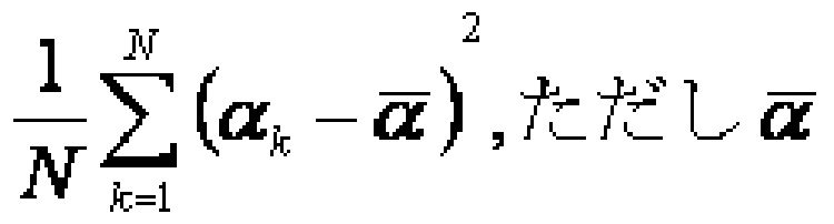
[0106] 道路画像 410(図 4参照)又は直線投票空間内のある点、又は、その周辺を通過す る直泉の本数を Nとし、各直泉を Ll、 L2、 ······、 LNとする。
[0107] また、直線 Lk、 k=l、 2、……、 Nの水平線とのなす角度および Hough変換手段での 投票値をそれぞれ a k、 wkとする。
[0108] ここで、直線ばらつき評価値を a kの分散 丄
•••(1)
kの重み付き分散

•••(2)
などの分散値や、これらの平方根をとつた標準偏差、又は《kの最大値と最小値の差
max ak _ miri ak
k k
•••(3)
等として算出することが出来る。
[0109] ただし、直線ばらつき評価値はこれに限定されるものではなぐ当該点又は当該点 周囲の所定の範囲を通過する直線の角度がばらついている程大きな値になるもので あればよい。
[0110] 次に、本実施例の動作について、図 6、図 7及び図 10のフローチャートを参照して 詳細に説明する。
[0111] 図 6 (A)の画像入力装置 610が、道路画像を入力する(図 10のステップ Bl)。
[0112] 次に、図 7 (B)の 3x3ソーベルフィルタ手段 711が、道路画像 410 (図 4参照)の各 点について、ソーベル X成分とソーベル y成分を算出する(ステップ B2)。
[0113] 次に、図 7 (B)のエッジ強度計算手段 712が、道路画像の各点についてエッジ強度 を計算する (ステップ B3)。
[0114] 次に、図 7 (B)のエッジ強度閾値処理手段 713が、道路画像の各点についてエッジ 強度を閾値処理する(ステップ B4)。
[0115] 次に、図 7 (B)のエッジ点出力手段 714が、エッジ強度が閾値以上の点をエッジ点 として検出する (ステップ B5)。
[0116] 次に、図 7 (A)の Hough空間投票手段 721が、各エッジ点について Hough空間内の 軌跡上に投票を行う(ステップ B6)。
[0117] 次に、図 7 (A)の Hough空間平滑化手段 722が、 Hough空間内の各点の投票値を 平滑化する(ステップ B 7)。
[0118] 次に、図 7 (A)の Hough空間ピーク検出手段 723が、 Hough空間内のピーク点を検 出する(ステップ B8)。
[0119] 次に、図 7 (A)の直線出力手段 730が、各 Hough空間ピーク点に対応する直線を 検出する(ステップ B9)。
[0120] ここで、直線が複数検出されて!/、れば、ステップ Bl 1に進み、直線が複数検出され ていなければ終了する(ステップ B10)。
[0121] 次に、図 6 (A)の直線角度ばらつき評価値付与手段 631が、直線投票空間の各点 について直線角度ばらつき評価値を算出する(ステップ Bl 1)。
[0122] 次に、図 6 (B)の直線投票手段 634が、図 7 (A)の Hough変換手段 720において検 出された各直線の軌跡上の点に対応する直線投票空間の点に、例えば Hough空間 ピーク検出手段 723で検出したピークの直線投票値を投票する (ステップ B12)。
[0123] 次に、図 6 (B)の消失点評価値算出手段 635が、直線投票空間の各点での消失点 評価値を消失点投票値と直線角度ばらつき評価値とから、例えばそれらの積として 算出する (ステップ B 13)。
[0124] 次に、図 6 (A)の消失点決定手段 633が、直線投票空間内での消失点投票値のピ ーク点に対応する消失点を検出する (ステップ B14)。
[0125] 次に、図 6 (A)の消失点出力手段 640が、消失点決定手段 633で検出した消失点 を出力する(ステップ B15)。
[0126] また、本実施例の応用例として、図 5 (A)に示すような自車両 510と道路面 530との 間のピッチ角( Θ ) 540を算出すること力 Sできる。
[0127] すなわち、図 5 (B)に示すように、焦点距離 S既知のカメラ画像面 522およびカメラ 座標系 (X, y)をとり、消失点の座標を (XV, yv)とすると、ピッチ角( Θ ) 540を式 (4)のよ うに定める。 yv=— fcos ( θ )より、
[0128]
θ = arccos
-•(4)
[0129] ただし、ピッチ角 Θの算出は、式 (4)に限定されるものではなぐ式 (4)を近似的に 算出するような算法によってもよい。
[0130] 次に、本発明の第 2の実施の形態について図面を参照して詳細に説明する。図 11 は、本発明の第 2の実施の形態の構成を示す図である。
[0131] 図 11を参照すると、本発明の第 2の実施の形態は、プログラム制御により動作する コンピュータ(中央処理装置;プロセッサ;データ処理装置) 1100と、画像入力装置 1 110とを備えて構成される。
[0132] コンピュータ(中央処理装置;プロセッサ;データ処理装置) 1100は、直線検出手 段 1120と、消失点検出手段 1130と、消失点出力手段 1140とを含む。
[0133] 消失点検出手段 1130は、直線投票手段 1131と、直線角度ばらつき評価値付与 手段 1132と、消失点評価値付与手段 1133と、消失点決定手段 1134とを含む。
[0134] これらの手段は、それぞれ概略つぎのように動作する。
[0135] 画像入力装置 1110は、消失点を検出する対象となる画像を入力する。
[0136] 直線検出手段 1120は、画像入力装置 1110が入力した画像から消失点を通過す ると推測される複数の直線を検出する。
[0137] 直線投票手段 1131は、画像入力装置 1110が入力した画像の少なくとも一部分を 含む 2次元空間内(以下、「直線投票空間」という)の各点について、直線検出手段 1
120で検出した複数の直線の内当該点又は当該点周囲の所定の範囲を通過する直 線に基づレ、た投票値を与える。
[0138] 直線角度ばらつき評価値付与手段 1132は、直線投票空間内の各点について、直 線投票手段 1131にて付与した当該点近傍の投票値に基づき、当該点又は当該点 周囲の所定の範囲を通過する直線の角度のばらつき具合を評価した直線角度ばら つき評価値を付与する。
[0139] 消失点評価値付与手段 1133は、直線投票空間内の各点について、直線投票手 段 1131にて各点に付与した投票値と角度ばらつき評価値とから当該点の消失点ら しさ具合を評価した消失点評価値を付与する。
[0140] ただし、消失点評価値付与手段 1133は、場合によっては省略してもよぐこの場合 は直線ばらつき評価値を消失点評価値として利用する。
[0141] 消失点決定手段 1134は、画像内又は直線投票空間内の各点に付与された消失 点評価値を用いて消失点を決定する。
[0142] 消失点出力手段 1140は、消失点決定手段 1134で決定された消失点を出力する
[0143] 次に、図 12は、本実施形態の動作を説明するフローチャートである。図 11、図 12 を参照して、本実施の形態の全体の動作について詳細に説明する。
[0144] まず、画像入力装置 1110が、消失点検出の対象である画像を入力する(図 12の
ステップ CI)。
[0145] 次に、直線検出手段 1120は、画像入力装置 1110が入力した画像から消失点を 通過すると推測される複数の直線を検出する (ステップ C2)。
[0146] 直線投票手段 1131が、直線投票空間においてステップ C2により検出した直線に 対応する投票を行う(ステップ C3)。
[0147] 直線角度ばらつき評価値付与手段 1132が、直線投票空間内の各点について、ス テツプ C3にて付与した当該点近傍の投票値に基づき当該点又は当該点周囲の所 定の範囲を通過する複数の直線についての直線角度ばらつき評価値を付与する(ス テツプ C4)。
[0148] 消失点評価値付与手段 1133が、画像内又は直線投票空間内の各点について、 ステップ C3にて各点に付与した投票値と直線角度ばらつき評価値とから消失点評価 値を付与する(ステップ C 5)。
[0149] ただし、ステップ C5を省略し、直線角度ばらつき評価値を前記消失点評価値として 禾 IJ用してあよい。
[0150] 消失点決定手段 1134が、直線投票空間内の各点に付与された消失点評価値を 用いて、例えば最大の消失点評価値を与える点を消失点とするなどして、消失点を 検出する(ステップ C6)。ただし、消失点評価値を用いた消失点検出方法は、これに 限定するものではなぐ例えば消失点評価値の極大値を与える点を消失点とする等 により消失点を検出することもできる。
[0151] 消失点出力手段 1140により検出された消失点を出力する(ステップ C7)。
[0152] 次に、本発明を第 2の実施形態の作用効果について説明する。
[0153] 本実施形態では、直線角度ばらつき評価値が直線投票空間内での近傍の投票値 に基づき算出するというように構成されているため、少ない処理量で直線角度ばらつ き評価値を算出でき、短!ヽ処理時間で偽の直線に対して頑健な消失点検出を行うこ と力 Sできる。
[0154] 次に、具体的な実施例に即して説明する。
[0155] <実施例 2〉
本実施例は、図 4に示した道路画像 410 (車載カメラから前方道路を撮像した画像
)力も走行レーンを表す白線 412や道路端 413等のエッジ部分を Hough変換により直 線として検出してそれらのなす消失点を検出する。
[0156] 図 13に示すように、本実施例は、車載カメラである画像入力装置 1310と、直線検 出手段 1320と、消失点検出手段 1330と、消失点出力手段 1340とを含む。
[0157] 消失点検出手段 1330は、直線投票手段 1331と、直線角度ばらつき評価値付与 手段 1332と、消失点評価値付与手段 1333と、消失点決定手段 1334とを含む。
[0158] 図 14 (A)は、図 13の直線検出手段の構成を示す図である。図 14 (B)は、図 14 (A
)のエッジ点検出手段 1410の構成を示す図である。図 14 (A)に示すように、直線検 出手段 1320は、エッジ点検出手段 1410と、 Hough変換手段 1420と、直線出力手 段 1430とを含む。
[0159] 図 14 (B)に示すように、エッジ点検出手段 1410は、 3 X 3ソーベルフィルタ手段 14 11と、エッジ強度計算手段 1412と、エッジ強度閾値処理手段 1413と、エッジ点出 力手段 1414とを含む。ただし、エッジ点検出手段 1410は構成に限定されるもので はなぐ画素値の変化が急峻なエッジ部分の点(以下、エッジ点と呼ぶ)を検出する 手段であればよい。
[0160] 図 14 (A)に示すように、 Hough変換手段 1420は、 Hough空間投票手段 1421と、 H ough空間平滑化手段 1422と、 Hough空間ピーク検出手段 1423とを含む。
[0161] 図 13の画像入力装置 1310は、道路画像 410 (図 4参照)を入力する。
[0162] 直線検出手段 1320は、道路画像 410 (図 4参照)から走行レーンを表す白線 412 や道路端 413等のエッジ部分を Hough変換により直線として検出する。
[0163] また、図 13の消失点検出手段 1330は、直線検出手段 1320により検出された直線 が集中する点を消失点として検出する。
[0164] 図 13の消失点出力手段 1340は、消失点を出力する。
[0165] 図 14 (B)の 3x3ソーベルフィルタ手段 1411は、道路画像 410 (図 4参照)の各点に ついて 3 X 3近傍中の各画素値と、図 8 (A)、図 8 (B)に示す X方向勾配カーネル 80 l、y方向勾配カーネル 802の各係数の積の和をとる。これらの積和をそれぞれ、「ソ 一ベル X成分」、「ソーベル y成分」と呼ぶ。
[0166] 図 14 (B)のエッジ強度計算手段 1412は、道路画像 410 (図 4参照)の各点につい
てソーベル X成分とソーベル y成分の 2乗和の平方、又は絶対値の和を計算し、各点 のエッジ強度とする。
[0167] 図 14 (B)のエッジ強度閾値処理手段 1413は、道路画像 410 (図 4参照)の各点に ついてエッジ強度が予め定められた閾値、例えば 100以上か否かを判断する。
[0168] 図 14 (B)のエッジ点出力手段 1414は、エッジ強度閾値処理手段 1413でエッジ強 度が閾値以上と判断された点をエッジ点として出力する。
[0169] 図 14 (A)の Hough空間投票手段 1421は、直線を表現するパラメータを軸とする空 間(以下、 Hough空間と呼ぶ)内において、エッジ点検出手段 1410で検出されたエツ ジ点に対応する軌跡上の各点について、エッジ点に応じた重みを投票する。
[0170] ここで、エッジ点に応じた重みとしてエッジ強度を投票する。ただし、エッジ点に応じ た重みはこれに限定されるものではなぐ前述したように、例えば定数、後述のソ一べ ル X成分とソーベル y成分により算出されるエッジ点における画素値の勾配と軌跡上 の点に対応する直線の傾きとのなす角など、エッジ点又はその近傍の画素値等から 算出される値、又はこれらの値やエッジ強度等から算出される値等を用いてもよい。
[0171] 図 14 (A)の Hough空間平滑化手段 1422は、 Hough空間の各点について、当該点 および近傍の点の投票値 (以下、「直線投票値」と呼ぶ)を用いて当該点での平滑化 された直線投票値を決定する。
[0172] ここでは、例えば、前記当該点の 3 X 3近傍の点の平均値として平滑化された直線 投票値を決定する。ただし、近傍の範囲や平滑化された直線投票値の決定方法はこ れに限定されるものではない。また、場合によっては、図 14 (A)の Hough空間平滑化 手段 1422を省略してもよい。
[0173] 図 14 (A)の Hough空間ピーク検出手段 1423は、 Hough空間内において予め定め られた閾値以上であり、かつ例えば 3 X 3近傍等の近傍範囲で最大の直線投票値を 持つ点をピークとして検出する。ただし、ピークを検出する基準はこれに限定されるも のではなぐ例えば、 Hough空間内での最大直線投票値をもつ点のみをピークとする 等、問題設定に応じた基準をとることが出来る。
[0174] 図 13の直線投票手段 1331は、図 14 (A)の Hough変換手段 1420において検出さ れた各直線の軌跡上の点に対応する直線投票空間の点に、例えば、図 14 (A)の Ho
ugh空間ピーク検出手段 1423で検出したピークの直線投票値を投票する(以下、「 消失点投票値」と呼ぶ)。ただし、投票値は、これに限定されるものではなぐ直線上 の点であることが確かであるほど大きな値をもつ投票値であればよい。
[0175] 図 13の直線角度ばらつき評価値付与手段 1332は、直線投票空間内の各点につ いて近傍の消失点投票値に基づき直線角度ばらつき評価値を算出し、付与する。
[0176] 図 13の消失点評価値付与手段 1333は、直線投票空間の各点について、当該点 又はその近傍の消失点投票値と直線角度ばらつき評価値とから消失点評価値を算 出し、付与する。
[0177] 図 13の消失点決定手段 1334は、例えば直線投票空間内で消失点評価値が最大 である点を消失点として決定する。ただし、消失点決定の基準は、これに限定される ものではなぐ例えば予め定められた閾値以上の消失点評価値をもつ点、または予 め定められた近傍内にて極大値をもつ点、又はこれらの条件の組み合わせ等、問題 設定に応じた基準をとることが出来る。
[0178] 直線角度ばらつき評価値について以下に説明する。
[0179] 前述のように、直線角度ばらつき評価値は当該点又は当該点周囲の所定の範囲を 通過する直線の角度がばらついている程大きな値をもつように算出される。
[0180] ここでは、特に図 15に示すような、消失点 1510の右下領域 1520を通過する直線 と左下領域 1530を通過する直線とが偏り無く存在するという意味において消失点 15 10における直線角度のばらつきが大きいと仮定できる場合を想定しており、このよう な状況は画像 1500として、本実施例のような道路画像を対象とした場合には当ては
[0181] そこで、本実施例では、直線投票空間内の各点において、当該点の近傍の消失点 投票値に基づき以下のように直線角度ばらつき評価値の算出を行う。
[0182] すなわち、図 16に示すように、当該点 1610の右下領域 1620での消失点投票値 の和を Sr、左下領域 1630での消失点投票値の和を SIとして、式(5)のように算出す
[0183]
2- 111111(5^^ )
•••(5)
[0184] ただし、直線角度ばらつき評価値の算出は式(5)に限定されるものではなぐ図 16 の当該点 1610の右下領域 1620内の消失点投票値と左下領域 1630内の消失点投 票値とが偏り無く存在する場合に値が大きくなるような他の算出式を用いることが出 来る。
[0185] また、右下領域 1620および左下領域 1630として、例えばサイズ 13 X 13の正方領 域等をとることが出来る力 これらはこれに限定されるものではなぐ用途に応じた領 域をとること力 S出来る。
[0186] 図 17は、本実施例の動作を説明するフローチャートである。図 13、図 14及び図 17 を参照して、本実施例の動作について詳細に説明する。
[0187] まず、図 13の画像入力装置 1310が、道路画像を入力する(図 17のステップ Dl)。
[0188] 次に、図 14 (B)の 3x3ソーベルフィルタ手段 1411により道路画像 410 (図 4参照)の 各点についてソーベル X成分とソーベル y成分を算出する(ステップ D2)。
[0189] 次に、図 14 (B)のエッジ強度計算手段 1412が、道路画像の各点についてエッジ 強度を計算する (ステップ D3)。
[0190] 次に、図 14 (B)のエッジ強度閾値処理手段 1413が、道路画像の各点についてェ ッジ強度を閾値処理する(ステップ D4)。
[0191] 次に、図 14 (B)のエッジ点出力手段 1414が、エッジ強度が閾値以上の点をエッジ 点として検出する (ステップ D5)。
[0192] 次に、図 14 (A)の Hough空間投票手段 1421が、各エッジ点について Hough空間 内の軌跡上に投票を行う(ステップ D6)。
[0193] 次に、図 14 (A)の Hough空間平滑化手段 1422が、 Hough空間内の各点の投票値 を平滑化する(ステップ D7)。
[0194] 次に、図 14 (A)の Hough空間ピーク検出手段 1423が、 Hough空間内のピーク点を
検出する(ステップ D8)。
[0195] 次に、図 14 (A)の直線出力手段 1430が、各 Hough空間ピーク点に対応する直線 を検出する(ステップ D9)。
[0196] ここで、直線が複数検出されて!/、れば、ステップ Dl 1に進み、直線が複数検出され ていなければ、終了する(ステップ D10)。
[0197] 次に、図 13の直線投票手段 1331が、図 14 (A)の Hough変換手段 1420において 検出された各直線の軌跡上の点に対応する直線投票空間の点に、例えば図 14 (A) の Hough空間ピーク検出手段 1423で検出したピークの直線投票値を投票する(ステ ップ Dl l)。
[0198] 次に、図 13の直線角度ばらつき評価値付与手段 1332が、直線投票空間の各点 について、当該点近傍の消失点投票値に基づき直線角度ばらつき評価値を算出す る(ステップ D 12)。
[0199] 次に、図 13の消失点評価値付与手段 1333が、直線投票空間の各点での消失点 評価値を消失点投票値と直線角度ばらつき評価値とから、例えばそれらの積として 算出する (ステップ D 13)。
[0200] 次に、図 13の消失点決定手段 1334が、直線投票空間内での消失点投票値のピ ーク点に対応する消失点を検出する (ステップ D14)。
[0201] 次に、図 13の消失点出力手段 1340が、検出した消失点を出力する (ステップ D15
)。
[0202] 本発明は、画像からの無限遠点以外の消失点の検出を行う任意の用途に適用でき る。以上、本発明を上記実施例に即して説明したが、本発明は上記実施例の構成に のみ制限されるものでなぐ本発明の範囲内で当業者であればなし得るであろう各種 変形、修正を含むことは勿論である。
Claims
[1] 画像から直線を検出する直線検出手段と、
前記画像の少なくとも一部を含む空間内の各点について、該点又は該点の周囲の 所定の範囲内を通過する直線の角度力 相対的に広い範囲に疎に分布している場 合に、より大きな値をとる直線角度ばらつき評価値を付与する直線角度ばらつき評価 値付与手段と、
前記直線角度ばらつき評価値を消失点評価値として用い、前記直線角度ばらつき 評価値が他と比べて相対的に大きな値をとる点を、消失点として、検出する消失点検 出手段と、
を備えた、ことを特徴とする消失点検出システム。
[2] 前記直線角度ばらつき評価値付与手段は、前記画像内において、複数の直線が その上を通過する点又は複数の直線がその近傍を通過する点に関して、直線の角 度のばらつき具合を表す評価値として前記直線角度ばらつき評価値を算出し、 前記消失点検出手段は、複数の直線がその上を通過するか又はその近傍を通過 する点に対応して導出された直線角度ばらつき評価値を、消失点らしさの指標として 用い、直線角度ばらつき評価値が、他の点に関して導出された直線角度ばらつき評 価値に比べて相対的に大きい値の点を、消失点として検出する、ことを特徴とする請 求項 1記載の消失点検出システム。
[3] 画像から直線を検出し、検出された各前記直線につ!/、て、直線としての確信度を 付与する直線検出手段と、
前記画像の少なくとも一部を含む空間内の各点について、該点又は該点周囲の所 定の範囲内を通過する直線の角度力 相対的に広い範囲に疎に分布している場合 に、より大きな値をとる直線角度ばらつき評価値を付与する直線角度ばらつき評価値 付与手段と、
前記画像の少なくとも一部を含む空間内の各点について、該点又は該点周囲の所 定の範囲内を通過する直線の確信度に基づき、直線が相対的に多数通過している 場合に、より大きな値をとる消失点評価値を付与する消失点評価値付与手段と、 前記消失点評価値が相対的に大きな値をとる点を、消失点として、検出する消失
点検出手段と、
を備え、
前記消失点評価値付与手段は、前記消失点評価値の算出に際して、前記直線角 度ばらつき評価値を考慮する、ことを特徴とする消失点検出システム。
[4] 前記直線検出手段は、 Hough変換により直線を検出し、
前記直線としての確信度として、該直線の Hough変換での投票値を用いる、ことを 特徴とする請求項 1乃至 3のいずれか一記載の消失点検出システム。
[5] 前記直線角度ばらつき評価値として、前記直線の角度の統計値が用いられる、こと を特徴とする請求項 1乃至 4のいずれか一に記載の消失点検出システム。
[6] 前記直線の角度の統計値は、前記直線の角度の分散と標準偏差、最大値と最小 値の差と比のうちの少なくとも 1つを含む、ことを特徴とする請求項 5記載の消失点検 出システム。
[7] 前記直線角度ばらつき評価値として、該点の右下領域と左下領域との間の前記直 線としての確信度の偏りが用いられる、ことを特徴とする請求項 1乃至 4のいずれか一 に記載の消失点検出システム。
[8] 前記画像は、車載センサより得られる画像データであり、
前記消失点として、走行レーンを表すレーンマーカ及び/又は道路端線に関する 消失点を検出する、ことを特徴とする請求項 1乃至 7のいずれか一に記載の消失点 検出システム。
[9] 請求項 1乃至 8のいずれか一に記載の消失点検出システムを備え、
前記消失点の位置に基づき、車両と周辺環境との位置関係を算出する、ことを特 徴とする車両周辺環境認識システム。
[10] 前記車両と周辺環境との位置関係として、前記車両の向いている方向と道路面と のピッチ角を算出する、ことを特徴とする請求項 9に記載の車両周辺環境認識システ ム。
[11] 画像から直線を検出する工程と、
前記画像の少なくとも一部を含む空間内の各点について、該点又は該点周囲の所 定の範囲内を通過する直線の角度力 相対的に広い範囲に疎に分布している場合
に、より大きな値をとる、直線角度ばらつき評価値を付与する工程と、 前記直線角度ばらつき評価値を消失点評価値として用い、前記直線角度ばらつき 評価値が相対的に大きな値をとる点を消失点として検出する工程と、
を含む、ことを特徴とする消失点検出方法。
[12] 画像から直線を、直線としての確信度とともに検出する工程と、
前記画像の少なくとも一部を含む空間内の各点について、該点又は該点周囲の所 定の範囲内を通過する直線の角度力 相対的に広い範囲に疎に分布している場合 に、より大きな値をとる直線角度ばらつき評価値を付与する工程と、
前記画像の少なくとも一部を含む空間内の各点について、該点又は該点周囲の所 定の範囲内を通過する直線の確信度に基づき、相対的に直線が多数通過している 場合に、より大きな値をとる消失点評価値を付与する工程と、
前記消失点評価値が相対的に大きな値をとる点を消失点として検出する工程と、 を含み、前記消失点評価値の算出に際して前記直線角度ばらつき評価値を考慮 する、ことを特徴とする消失点検出方法。
[13] 前記画像から直線を検出する工程にお!/ヽて、
Hough変換により直線を検出し、
前記直線としての確信度として、該直線の Hough変換での投票値を用いる、ことを 特徴とする請求項 11又は 12に記載の消失点検出方法。
[14] 前記直線角度ばらつき評価値として、前記直線の角度についての統計値を用いる
、ことを特徴とする請求項 11乃至 13のいずれか一に記載の消失点検出方法。
[15] 前記直線の角度についての統計値は、前記直線の角度の分散と標準偏差、最大 値と最小値の差と比、のうちの少なくとも 1つを含む、ことを特徴とする請求項 14記載 の消失点検出方法。
[16] 前記直線角度ばらつき評価値として、該点の右下領域と左下領域との間の前記直 線としての確信度の偏りを用いる、ことを特徴とする請求項 11乃至 13の!/、ずれか一 に記載の消失点検出方法。
[17] 前記画像として車載センサより得られる画像データを用い、
前記消失点として走行レーンを表すレーンマーカ及び/又は道路端線に関する消
失点を検出する、ことを特徴とする請求項 11乃至 16のいずれか一に記載の消失点 検出方法。
[18] 請求項 11乃至 17のいずれか一に記載の消失点検出方法で求めた前記消失点の 位置に基づき、車両と周辺環境との位置関係を算出する、ことを特徴とする車両周辺 環境認識方法。
[19] 前記車両と周辺環境との位置関係として、車両の向いている方向と道路面とのピッ チ角を算出する、ことを特徴とする請求項 18に記載の車両周辺環境認識方法。
[20] 消失点の検出を行うコンピュータに、
画像から直線を検出する直線検出処理と、
前記画像の少なくとも一部を含む空間内の各点について、該点又は該点周囲の所 定の範囲内を通過する直線の角度力 相対的に広い範囲に疎に分布している場合 に、より大きな値をとる直線角度ばらつき評価値を付与する直線角度ばらつき評価値 付与処理と、
前記直線角度ばらつき評価値を消失点評価値として用い、前記直線角度ばらつき 評価値が相対的に大きな値をとる点を消失点として検出する消失点検出処理と、 を実行させるプログラム。
[21] 前記直線検出処理として、画像から直線を、直線としての確信度とともに検出する 処理と、
前記直線角度ばらつき評価値付与処理として、前記画像の少なくとも一部を含む 空間内の各点について、該点又は該点周囲の所定の範囲内を通過する直線の角度 1S 相対的に広い範囲に疎に分布している場合に、より大きな値をとる直線角度ばら つき評価値を付与する処理と、
前記画像の少なくとも一部を含む空間内の各点について、該点又は該点周囲の所 定の範囲内を通過する直線の確信度に基づき、直線が相対的に多数通過している 場合よりも大きな値をとる消失点評価値を付与し、その際、前記直線角度ばらつき評 価値を考慮して前記消失点評価値を算出する消失点評価値付与処理と、
前記消失点検出処理として、前記消失点評価値が相対的に大きな値をとる点を消 失点として検出する処理と、
を前記コンピュータに実行させる請求項 20記載のプログラム。
[22] 前記直線検出処理は、 Hough変換により直線を検出し、前記直線としての確信度と して該直線の Hough変換での投票値を用いる、ことを特徴とする請求項 20又は 21に 記載のプログラム。
[23] 前記直線角度ばらつき評価値として、前記直線の角度についての統計値を用いる 、ことを特徴とする請求項 20乃至 22のいずれか一に記載のプログラム。
[24] 前記直線の角度についての統計値は、前記直線の角度の、分散と標準偏差、最大 値と最小値の差と比、の少なくとも 1つを含む、ことを特徴とする請求項 23記載のプロ グラム。
[25] 前記直線角度ばらつき評価値として、該点の右下領域と左下領域との間の前記直 線としての確信度の偏りを用いる、ことを特徴とする請求項 20乃至 22のいずれか一 に記載のプログラム。
[26] 前記画像として、車載センサより得られるデータを用い、
前記消失点として走行レーンを表すレーンマーカや道路端線に関する消失点を検 出する処理を、前記コンピュータに実行させる、ことを特徴とする請求項 20乃至 25の いずれか一に記載のプログラム。
[27] 導出された前記消失点の位置に基づき、車両と周辺環境との位置関係を算出し、 前記車両周辺の環境認識を行う処理を、前記コンピュータに実行させる、ことを特徴 とする請求項 20乃至 25のいずれか一に記載のプログラム。
[28] 前記車両と周辺環境との位置関係として、車両の向いている方向と道路面とのピッ チ角を算出する、ことを特徴とする請求項 25に記載のプログラム。
Priority Applications (2)
| Application Number | Priority Date | Filing Date | Title |
|---|---|---|---|
| EP07831278A EP2098992A4 (en) | 2006-11-08 | 2007-11-06 | LEAK POINT DETECTION SYSTEM, LEAK POINT DETECTING METHOD, AND LEAK POINT DETECTING PROGRAM |
| US12/514,108 US8396299B2 (en) | 2006-11-08 | 2007-11-06 | Vanishing point detecting system, vanishing point detecting method, and vanishing point detecting program |
Applications Claiming Priority (2)
| Application Number | Priority Date | Filing Date | Title |
|---|---|---|---|
| JP2006-302955 | 2006-11-08 | ||
| JP2006302955A JP4222411B2 (ja) | 2006-11-08 | 2006-11-08 | 消失点検出システム、消失点検出方法および消失点検出用プログラム |
Publications (1)
| Publication Number | Publication Date |
|---|---|
| WO2008056660A1 true WO2008056660A1 (en) | 2008-05-15 |
Family
ID=39364475
Family Applications (1)
| Application Number | Title | Priority Date | Filing Date |
|---|---|---|---|
| PCT/JP2007/071546 Ceased WO2008056660A1 (en) | 2006-11-08 | 2007-11-06 | Vanishing point detecting system, vanishing point detecting method, and vanishing point detecting program |
Country Status (4)
| Country | Link |
|---|---|
| US (1) | US8396299B2 (ja) |
| EP (1) | EP2098992A4 (ja) |
| JP (1) | JP4222411B2 (ja) |
| WO (1) | WO2008056660A1 (ja) |
Cited By (2)
| Publication number | Priority date | Publication date | Assignee | Title |
|---|---|---|---|---|
| EP2228666A1 (en) | 2009-03-11 | 2010-09-15 | Honeywell International Inc. | Vision-based vehicle navigation system and method |
| US8177381B2 (en) | 2010-03-30 | 2012-05-15 | Skc Haas Display Films Co., Ltd. | Diffusion bar with spacer collar ring |
Families Citing this family (31)
| Publication number | Priority date | Publication date | Assignee | Title |
|---|---|---|---|---|
| JP5011268B2 (ja) * | 2008-12-02 | 2012-08-29 | 三菱電機株式会社 | 画像検出装置及び画像検出方法 |
| JP5321497B2 (ja) * | 2010-02-22 | 2013-10-23 | 株式会社デンソー | 白線認識装置 |
| WO2011117950A1 (ja) | 2010-03-23 | 2011-09-29 | 日本電気株式会社 | 線状マーク検出システム、線状マーク検出方法および線状マーク検出用プログラムが格納された非一時的なコンピュータ可読媒体 |
| DE102010044112B4 (de) | 2010-06-16 | 2022-12-29 | Denso Corporation | Fluchtpunktbestimmungsvorrichtung und Fluchtpunktbestimmungsprogramm |
| JP2012093872A (ja) * | 2010-10-26 | 2012-05-17 | Fujitsu Ten Ltd | 画像認識装置、及び、画像認識方法 |
| KR101264282B1 (ko) * | 2010-12-13 | 2013-05-22 | 재단법인대구경북과학기술원 | 관심영역 설정을 이용한 도로상 차량의 검출방법 |
| JP2013050762A (ja) * | 2011-08-30 | 2013-03-14 | Mega Chips Corp | 線分および円弧検出装置 |
| EP2752817A4 (en) | 2011-08-30 | 2016-11-09 | Megachips Corp | DEVICE FOR DETECTION OF CABLE SEGMENTS AND BELLS |
| JP6049000B2 (ja) * | 2011-09-21 | 2016-12-21 | 株式会社メガチップス | 線分および円弧検出装置 |
| CN103164851B (zh) * | 2011-12-09 | 2016-04-20 | 株式会社理光 | 道路分割物检测方法和装置 |
| CN102609938B (zh) * | 2012-01-16 | 2014-04-16 | 浙江大学 | 一种从单幅图像检测道路消失点的方法 |
| CN103577790B (zh) * | 2012-07-26 | 2016-06-01 | 株式会社理光 | 道路转弯类型检测方法和装置 |
| ITVI20120303A1 (it) * | 2012-11-09 | 2014-05-10 | St Microelectronics Srl | Metodo per rilevare una linea retta in un'immagine digitale |
| CN103854008B (zh) * | 2012-12-04 | 2019-10-18 | 株式会社理光 | 路面检测方法和装置 |
| US9123113B2 (en) * | 2013-03-08 | 2015-09-01 | Raven Industries, Inc. | Row guidance parameterization with Hough transform |
| US9747507B2 (en) * | 2013-12-19 | 2017-08-29 | Texas Instruments Incorporated | Ground plane detection |
| KR101569165B1 (ko) | 2014-03-03 | 2015-11-13 | 서울대학교 산학협력단 | 소실점 검출 방법 및 장치 |
| JP6299371B2 (ja) | 2014-04-18 | 2018-03-28 | 富士通株式会社 | 撮像方向の傾き検出方法、撮像方向の傾き検出プログラムおよび撮像方向の傾き検出装置 |
| JP6264173B2 (ja) | 2014-04-18 | 2018-01-24 | 富士通株式会社 | 撮像方向の正常性判定方法、撮像装置取り付け状態評価プログラムおよび撮像装置取り付け状態評価装置 |
| JP6299373B2 (ja) | 2014-04-18 | 2018-03-28 | 富士通株式会社 | 撮像方向の正常性の判定方法、撮像方向の正常性の判定プログラムおよび撮像方向の正常性の判定装置 |
| DE102014220199B3 (de) * | 2014-10-06 | 2016-01-14 | Continental Automotive Gmbh | Verfahren für ein Kraftfahrzeug mit einer Kamera, Vorrichtung und System |
| WO2016178335A1 (ja) * | 2015-05-07 | 2016-11-10 | 株式会社日立製作所 | レーン検出装置およびレーン検出方法 |
| JP6208789B2 (ja) * | 2016-02-17 | 2017-10-04 | 株式会社メガチップス | 直線検出装置および直線検出方法 |
| US10650526B2 (en) * | 2016-06-28 | 2020-05-12 | Canon Kabushiki Kaisha | Image processing apparatus, image capturing apparatus, image processing method, and storage medium |
| RU2651176C1 (ru) * | 2016-11-17 | 2018-04-18 | Федеральное государственное бюджетное образовательное учреждение высшего образования "Рязанский государственный радиотехнический университет" | Способ обработки сигналов для обнаружения и определения толщины прямых линий на изображении |
| WO2020014683A1 (en) * | 2018-07-13 | 2020-01-16 | Kache.AI | Systems and methods for autonomous object detection and vehicle following |
| CN113486797B (zh) * | 2018-09-07 | 2023-08-11 | 百度在线网络技术(北京)有限公司 | 无人车位置检测方法、装置、设备、存储介质及车辆 |
| KR102677513B1 (ko) | 2018-10-23 | 2024-06-21 | 삼성전자주식회사 | 소실점 검출을 위한 학습 방법, 소실점 검출 방법 및 장치 |
| CN111798431B (zh) * | 2020-07-06 | 2023-09-15 | 苏州市职业大学 | 一种实时消失点检测方法、装置、设备及存储介质 |
| KR20220160850A (ko) | 2021-05-28 | 2022-12-06 | 삼성전자주식회사 | 소실점을 추정하는 방법 및 장치 |
| CN114037977B (zh) * | 2022-01-07 | 2022-04-26 | 深圳佑驾创新科技有限公司 | 道路灭点的检测方法、装置、设备及存储介质 |
Citations (4)
| Publication number | Priority date | Publication date | Assignee | Title |
|---|---|---|---|---|
| JP2000123300A (ja) * | 1998-10-14 | 2000-04-28 | Nec Corp | 消失点による補正を伴う白線検出方法及び装置 |
| JP2003228711A (ja) * | 2001-11-30 | 2003-08-15 | Hitachi Ltd | レーンマーク認識方法 |
| JP2005275500A (ja) | 2004-03-23 | 2005-10-06 | Zenrin Co Ltd | 消失点決定方法 |
| JP2006302955A (ja) | 2005-04-15 | 2006-11-02 | Sony Corp | 面発光半導体レーザ |
Family Cites Families (11)
| Publication number | Priority date | Publication date | Assignee | Title |
|---|---|---|---|---|
| DE19680415C2 (de) * | 1995-04-26 | 2003-02-06 | Hitachi Ltd | Bildbearbeitungsvorrichtung für Fahrzeuge |
| JP3556766B2 (ja) * | 1996-05-28 | 2004-08-25 | 松下電器産業株式会社 | 道路白線検出装置 |
| JPH10208056A (ja) * | 1997-01-16 | 1998-08-07 | Honda Motor Co Ltd | 直線検出方法 |
| JP2986439B2 (ja) * | 1998-01-12 | 1999-12-06 | 松下電器産業株式会社 | 車両用画像処理装置 |
| JP4157620B2 (ja) * | 1998-06-19 | 2008-10-01 | 株式会社東芝 | 移動物体検出装置及びその方法 |
| JP2000259998A (ja) * | 1999-03-12 | 2000-09-22 | Yazaki Corp | 車両用後側方監視装置 |
| JP3575346B2 (ja) * | 1999-09-03 | 2004-10-13 | 日本電気株式会社 | 道路白線検出システム、道路白線検出方法および道路白線検出用プログラムを記録した記録媒体 |
| US6963661B1 (en) * | 1999-09-09 | 2005-11-08 | Kabushiki Kaisha Toshiba | Obstacle detection system and method therefor |
| US6844871B1 (en) * | 1999-11-05 | 2005-01-18 | Microsoft Corporation | Method and apparatus for computer input using six degrees of freedom |
| JP4437714B2 (ja) * | 2004-07-15 | 2010-03-24 | 三菱電機株式会社 | 車線認識画像処理装置 |
| JP4466963B2 (ja) * | 2005-01-11 | 2010-05-26 | パイオニア株式会社 | 車両前方画像表示装置及び方法 |
-
2006
- 2006-11-08 JP JP2006302955A patent/JP4222411B2/ja active Active
-
2007
- 2007-11-06 EP EP07831278A patent/EP2098992A4/en not_active Withdrawn
- 2007-11-06 US US12/514,108 patent/US8396299B2/en active Active
- 2007-11-06 WO PCT/JP2007/071546 patent/WO2008056660A1/ja not_active Ceased
Patent Citations (4)
| Publication number | Priority date | Publication date | Assignee | Title |
|---|---|---|---|---|
| JP2000123300A (ja) * | 1998-10-14 | 2000-04-28 | Nec Corp | 消失点による補正を伴う白線検出方法及び装置 |
| JP2003228711A (ja) * | 2001-11-30 | 2003-08-15 | Hitachi Ltd | レーンマーク認識方法 |
| JP2005275500A (ja) | 2004-03-23 | 2005-10-06 | Zenrin Co Ltd | 消失点決定方法 |
| JP2006302955A (ja) | 2005-04-15 | 2006-11-02 | Sony Corp | 面発光半導体レーザ |
Non-Patent Citations (1)
| Title |
|---|
| See also references of EP2098992A4 |
Cited By (2)
| Publication number | Priority date | Publication date | Assignee | Title |
|---|---|---|---|---|
| EP2228666A1 (en) | 2009-03-11 | 2010-09-15 | Honeywell International Inc. | Vision-based vehicle navigation system and method |
| US8177381B2 (en) | 2010-03-30 | 2012-05-15 | Skc Haas Display Films Co., Ltd. | Diffusion bar with spacer collar ring |
Also Published As
| Publication number | Publication date |
|---|---|
| EP2098992A4 (en) | 2012-03-28 |
| US20100080467A1 (en) | 2010-04-01 |
| EP2098992A1 (en) | 2009-09-09 |
| JP2008123036A (ja) | 2008-05-29 |
| JP4222411B2 (ja) | 2009-02-12 |
| US8396299B2 (en) | 2013-03-12 |
Similar Documents
| Publication | Publication Date | Title |
|---|---|---|
| JP4222411B2 (ja) | 消失点検出システム、消失点検出方法および消失点検出用プログラム | |
| JP4794625B2 (ja) | 画像処理装置および画像処理方法 | |
| US7149327B2 (en) | Image processing apparatus and method | |
| US9076047B2 (en) | System and method for recognizing parking space line markings for vehicle | |
| US20150279021A1 (en) | Video object tracking in traffic monitoring | |
| JP5035371B2 (ja) | 横断歩道検出装置、横断歩道検出システム,横断歩道検出方法及びプログラム | |
| JP4577532B2 (ja) | 認識システム、認識方法および認識プログラム | |
| CN108345836A (zh) | 用于自主车辆的标志识别 | |
| US10013619B2 (en) | Method and device for detecting elliptical structures in an image | |
| US12299906B2 (en) | Estimating the movement of an image position | |
| CN104364796A (zh) | 用于处理立体数据的方法和设备 | |
| Kumar et al. | An efficient approach for highway lane detection based on the Hough transform and Kalman filter | |
| JP7072765B2 (ja) | 画像処理装置、画像認識装置、画像処理プログラム、及び画像認識プログラム | |
| JP6255944B2 (ja) | 画像解析装置、画像解析方法及び画像解析プログラム | |
| JP2019218022A (ja) | 線路検出装置 | |
| CN113147746A (zh) | 坡道车位的探测方法及装置 | |
| CN119964141A (zh) | 一种基于大模型优化的3d机器视觉检测方法 | |
| WO2018143278A1 (ja) | 画像処理装置、画像認識装置、画像処理プログラム、及び画像認識プログラム | |
| JP7595470B2 (ja) | 判定装置及び判定方法 | |
| KR101886856B1 (ko) | 이종센서 탐색기의 비정형 객체추적에 대한 데이터 결합시스템 및 방법 | |
| KR100946707B1 (ko) | 파노라마 이미지에 대한 이미지 매칭을 수행하기 위한 방법, 시스템 및 컴퓨터 판독 가능한 기록 매체 | |
| JPWO2008032375A1 (ja) | 画像補正装置及び方法、並びにコンピュータプログラム | |
| CN114627264A (zh) | 确定目标方向的方法以及用于追踪目标的方法和装置 | |
| CN119365899A (zh) | 借助机器学习方法识别车辆停车位的方法和装置 | |
| JP2005148784A (ja) | 路面走行レーン検出装置 |
Legal Events
| Date | Code | Title | Description |
|---|---|---|---|
| 121 | Ep: the epo has been informed by wipo that ep was designated in this application |
Ref document number: 07831278 Country of ref document: EP Kind code of ref document: A1 |
|
| WWE | Wipo information: entry into national phase |
Ref document number: 12514108 Country of ref document: US |
|
| NENP | Non-entry into the national phase |
Ref country code: DE |
|
| WWE | Wipo information: entry into national phase |
Ref document number: 2007831278 Country of ref document: EP |