WO2008109264A1 - Control of combined storage and generation in distributed energy resources - Google Patents
Control of combined storage and generation in distributed energy resources Download PDFInfo
- Publication number
- WO2008109264A1 WO2008109264A1 PCT/US2008/054572 US2008054572W WO2008109264A1 WO 2008109264 A1 WO2008109264 A1 WO 2008109264A1 US 2008054572 W US2008054572 W US 2008054572W WO 2008109264 A1 WO2008109264 A1 WO 2008109264A1
- Authority
- WO
- WIPO (PCT)
- Prior art keywords
- power
- set point
- energy storage
- determined
- storage device
- Prior art date
- Legal status (The legal status is an assumption and is not a legal conclusion. Google has not performed a legal analysis and makes no representation as to the accuracy of the status listed.)
- Ceased
Links
Classifications
-
- H—ELECTRICITY
- H02—GENERATION; CONVERSION OR DISTRIBUTION OF ELECTRIC POWER
- H02P—CONTROL OR REGULATION OF ELECTRIC MOTORS, ELECTRIC GENERATORS OR DYNAMO-ELECTRIC CONVERTERS; CONTROLLING TRANSFORMERS, REACTORS OR CHOKE COILS
- H02P9/00—Arrangements for controlling electric generators for the purpose of obtaining a desired output
- H02P9/04—Control effected upon non-electric prime mover and dependent upon electric output value of the generator
-
- H—ELECTRICITY
- H02—GENERATION; CONVERSION OR DISTRIBUTION OF ELECTRIC POWER
- H02J—ELECTRIC POWER NETWORKS; CIRCUIT ARRANGEMENTS OR SYSTEMS FOR SUPPLYING OR DISTRIBUTING ELECTRIC POWER; SYSTEMS FOR STORING ELECTRIC ENERGY
- H02J3/00—Circuit arrangements for AC mains or AC distribution networks
- H02J3/28—Arrangements for balancing of the load in networks by storage of energy
-
- H—ELECTRICITY
- H02—GENERATION; CONVERSION OR DISTRIBUTION OF ELECTRIC POWER
- H02J—ELECTRIC POWER NETWORKS; CIRCUIT ARRANGEMENTS OR SYSTEMS FOR SUPPLYING OR DISTRIBUTING ELECTRIC POWER; SYSTEMS FOR STORING ELECTRIC ENERGY
- H02J3/00—Circuit arrangements for AC mains or AC distribution networks
- H02J3/38—Arrangements for feeding a single network from two or more generators or sources in parallel; Arrangements for feeding already energised networks from additional generators or sources in parallel
- H02J3/381—Dispersed generators
-
- H—ELECTRICITY
- H02—GENERATION; CONVERSION OR DISTRIBUTION OF ELECTRIC POWER
- H02J—ELECTRIC POWER NETWORKS; CIRCUIT ARRANGEMENTS OR SYSTEMS FOR SUPPLYING OR DISTRIBUTING ELECTRIC POWER; SYSTEMS FOR STORING ELECTRIC ENERGY
- H02J9/00—Circuit arrangements for emergency or stand-by power supply, e.g. for emergency lighting
- H02J9/04—Circuit arrangements for emergency or stand-by power supply, e.g. for emergency lighting in which the distribution system is disconnected from the normal source and connected to a standby source
- H02J9/06—Circuit arrangements for emergency or stand-by power supply, e.g. for emergency lighting in which the distribution system is disconnected from the normal source and connected to a standby source with automatic change-over, e.g. UPS systems
- H02J9/062—Circuit arrangements for emergency or stand-by power supply, e.g. for emergency lighting in which the distribution system is disconnected from the normal source and connected to a standby source with automatic change-over, e.g. UPS systems for AC powered loads
-
- H—ELECTRICITY
- H02—GENERATION; CONVERSION OR DISTRIBUTION OF ELECTRIC POWER
- H02J—ELECTRIC POWER NETWORKS; CIRCUIT ARRANGEMENTS OR SYSTEMS FOR SUPPLYING OR DISTRIBUTING ELECTRIC POWER; SYSTEMS FOR STORING ELECTRIC ENERGY
- H02J2101/00—Supply or distribution of decentralised, dispersed or local electric power generation
- H02J2101/10—Dispersed power generation using fossil fuels, e.g. diesel generators
-
- H—ELECTRICITY
- H02—GENERATION; CONVERSION OR DISTRIBUTION OF ELECTRIC POWER
- H02J—ELECTRIC POWER NETWORKS; CIRCUIT ARRANGEMENTS OR SYSTEMS FOR SUPPLYING OR DISTRIBUTING ELECTRIC POWER; SYSTEMS FOR STORING ELECTRIC ENERGY
- H02J2101/00—Supply or distribution of decentralised, dispersed or local electric power generation
- H02J2101/20—Dispersed power generation using renewable energy sources
-
- H—ELECTRICITY
- H02—GENERATION; CONVERSION OR DISTRIBUTION OF ELECTRIC POWER
- H02J—ELECTRIC POWER NETWORKS; CIRCUIT ARRANGEMENTS OR SYSTEMS FOR SUPPLYING OR DISTRIBUTING ELECTRIC POWER; SYSTEMS FOR STORING ELECTRIC ENERGY
- H02J2101/00—Supply or distribution of decentralised, dispersed or local electric power generation
- H02J2101/20—Dispersed power generation using renewable energy sources
- H02J2101/22—Solar energy
- H02J2101/24—Photovoltaics
-
- H—ELECTRICITY
- H02—GENERATION; CONVERSION OR DISTRIBUTION OF ELECTRIC POWER
- H02J—ELECTRIC POWER NETWORKS; CIRCUIT ARRANGEMENTS OR SYSTEMS FOR SUPPLYING OR DISTRIBUTING ELECTRIC POWER; SYSTEMS FOR STORING ELECTRIC ENERGY
- H02J2101/00—Supply or distribution of decentralised, dispersed or local electric power generation
- H02J2101/20—Dispersed power generation using renewable energy sources
- H02J2101/28—Wind energy
-
- H—ELECTRICITY
- H02—GENERATION; CONVERSION OR DISTRIBUTION OF ELECTRIC POWER
- H02J—ELECTRIC POWER NETWORKS; CIRCUIT ARRANGEMENTS OR SYSTEMS FOR SUPPLYING OR DISTRIBUTING ELECTRIC POWER; SYSTEMS FOR STORING ELECTRIC ENERGY
- H02J3/00—Circuit arrangements for AC mains or AC distribution networks
- H02J3/38—Arrangements for feeding a single network from two or more generators or sources in parallel; Arrangements for feeding already energised networks from additional generators or sources in parallel
- H02J3/388—Arrangements for the handling of islanding, e.g. for disconnection or for avoiding the disconnection of power
-
- H—ELECTRICITY
- H02—GENERATION; CONVERSION OR DISTRIBUTION OF ELECTRIC POWER
- H02P—CONTROL OR REGULATION OF ELECTRIC MOTORS, ELECTRIC GENERATORS OR DYNAMO-ELECTRIC CONVERTERS; CONTROLLING TRANSFORMERS, REACTORS OR CHOKE COILS
- H02P2101/00—Special adaptation of control arrangements for generators
- H02P2101/15—Special adaptation of control arrangements for generators for wind-driven turbines
-
- Y—GENERAL TAGGING OF NEW TECHNOLOGICAL DEVELOPMENTS; GENERAL TAGGING OF CROSS-SECTIONAL TECHNOLOGIES SPANNING OVER SEVERAL SECTIONS OF THE IPC; TECHNICAL SUBJECTS COVERED BY FORMER USPC CROSS-REFERENCE ART COLLECTIONS [XRACs] AND DIGESTS
- Y02—TECHNOLOGIES OR APPLICATIONS FOR MITIGATION OR ADAPTATION AGAINST CLIMATE CHANGE
- Y02B—CLIMATE CHANGE MITIGATION TECHNOLOGIES RELATED TO BUILDINGS, e.g. HOUSING, HOUSE APPLIANCES OR RELATED END-USER APPLICATIONS
- Y02B10/00—Integration of renewable energy sources in buildings
- Y02B10/70—Hybrid systems, e.g. uninterruptible or back-up power supplies integrating renewable energies
-
- Y—GENERAL TAGGING OF NEW TECHNOLOGICAL DEVELOPMENTS; GENERAL TAGGING OF CROSS-SECTIONAL TECHNOLOGIES SPANNING OVER SEVERAL SECTIONS OF THE IPC; TECHNICAL SUBJECTS COVERED BY FORMER USPC CROSS-REFERENCE ART COLLECTIONS [XRACs] AND DIGESTS
- Y02—TECHNOLOGIES OR APPLICATIONS FOR MITIGATION OR ADAPTATION AGAINST CLIMATE CHANGE
- Y02E—REDUCTION OF GREENHOUSE GAS [GHG] EMISSIONS, RELATED TO ENERGY GENERATION, TRANSMISSION OR DISTRIBUTION
- Y02E10/00—Energy generation through renewable energy sources
- Y02E10/50—Photovoltaic [PV] energy
- Y02E10/56—Power conversion systems, e.g. maximum power point trackers
-
- Y—GENERAL TAGGING OF NEW TECHNOLOGICAL DEVELOPMENTS; GENERAL TAGGING OF CROSS-SECTIONAL TECHNOLOGIES SPANNING OVER SEVERAL SECTIONS OF THE IPC; TECHNICAL SUBJECTS COVERED BY FORMER USPC CROSS-REFERENCE ART COLLECTIONS [XRACs] AND DIGESTS
- Y02—TECHNOLOGIES OR APPLICATIONS FOR MITIGATION OR ADAPTATION AGAINST CLIMATE CHANGE
- Y02E—REDUCTION OF GREENHOUSE GAS [GHG] EMISSIONS, RELATED TO ENERGY GENERATION, TRANSMISSION OR DISTRIBUTION
- Y02E10/00—Energy generation through renewable energy sources
- Y02E10/70—Wind energy
- Y02E10/76—Power conversion electric or electronic aspects
-
- Y—GENERAL TAGGING OF NEW TECHNOLOGICAL DEVELOPMENTS; GENERAL TAGGING OF CROSS-SECTIONAL TECHNOLOGIES SPANNING OVER SEVERAL SECTIONS OF THE IPC; TECHNICAL SUBJECTS COVERED BY FORMER USPC CROSS-REFERENCE ART COLLECTIONS [XRACs] AND DIGESTS
- Y02—TECHNOLOGIES OR APPLICATIONS FOR MITIGATION OR ADAPTATION AGAINST CLIMATE CHANGE
- Y02E—REDUCTION OF GREENHOUSE GAS [GHG] EMISSIONS, RELATED TO ENERGY GENERATION, TRANSMISSION OR DISTRIBUTION
- Y02E70/00—Other energy conversion or management systems reducing GHG emissions
- Y02E70/30—Systems combining energy storage with energy generation of non-fossil origin
Definitions
- the field of the disclosure relates generally to power systems. More specifically, the disclosure relates to the control of storage and generation capabilities of a distributed energy resource included in a dynamic distribution system.
- DERs can provide reliable power in critical applications as a backup to the primary electrical supply. For example, an interruption of power to a hospital can have life-threatening consequences. Similarly, when power to a factory is interrupted, productivity is lost, materials in process are wasted, and other costs are incurred in association with restarting the production line. Additionally, power from a DER can be provided to the main power grid to reduce energy price peaks by arbitraging energy price differentials. Geographically distributed sources of power, such as wind, solar, or hydroelectric power, may be too limited or intermittent to be used as the basis for a centralized power plant.
- these types of power sources can supplement or replace conventional power sources when the main power grid is available and can provide a backup when the main power grid is unavailable to increase energy efficiency and to reduce pollution and greenhouse gas emissions through the use of combined heat and power DER systems.
- DERs also can be used to meet load growth requirements and to enhance the robustness of the transmission system with a minimal addition of new lines.
- DERs can include two broad categories of electrical power sources: Direct current (DC) sources, such as fuel cells, solar cells, and batteries; and high-frequency analog current (AC) sources, such as micro-turbines and wind turbines.
- DC Direct current
- AC high-frequency analog current
- Both types of sources are typically used to provide an intermediate DC voltage, that may be produced directly by DC sources, and produced indirectly from AC sources, for example by rectification.
- the intermediate DC voltage is subsequently converted to AC voltage or current at the required frequency, amplitude, and phase angle for use.
- the conversion from the intermediate DC voltage to the usable AC voltage is performed by a voltage inverter that can rapidly control the magnitude and phase of its output voltage.
- DERs may be designed to operate in one of two modes: (1 ) "isolation” or “island” mode, wherein the DER is isolated from the main grid, and (2) normal “grid” mode, wherein the DER is connected to the main grid to either import power from or export power to the main grid. Smooth and efficient transition between the two modes is a necessity to effectively integrate DERs into the distribution system without harming the integrity of the remaining system.
- a centralized electrical power utility is in a position to monitor and coordinate the production and distribution of power from multiple generators.
- DERs may include independent producers of power who have limited awareness or communication with each other. Even if the independent producers of power are able to communicate with each other, there may not be an effective way to ensure that they cooperate.
- Effective integration of DERs into the distribution system also benefits from fast acting energy sources, such as storage, which provide the energy required by the loads until slower sources ramp-up their energy output when a DER isolates from the distribution system.
- Storage sources also allow the exploitation of energy price differentials by charging of the DER when power costs are low (i.e. at night) and discharging of the DER when power costs are high (i.e. during peak loads).
- storage within an intermittent renewable such as a wind and/or a solar system can discharge when the renewable energy is low (no wind or sun) and charge when there is excess renewable energy (high wind at 2 a.m.).
- Both storage and generation can be clustered with each other to take advantage of the beneficial characteristics of both storage and generation.
- storage being inverter based can have a faster response to load demands than a generator.
- the storage can respond in a few electrical cycles while a traditional generator may take tens of cycles.
- generator cost generally is much less than energy storage based on a dollars/megawatt-hour comparison.
- a method and a system for effective utilization of power generation and storage resources within a DER system are provided in an exemplary embodiment.
- Each active component of the distribution system reacts to local information such as a voltage, a current, and a frequency to change its operating point.
- a coordination controller controls the operation of storage and generation through minimum and maximum power limits.
- the coordination controller controls the rate of charge and discharge and the charge level of the storage device and the mode of operation for the power generation device and the energy storage device. For example, the coordination controller determines which device tracks load and which may operate at a fixed output.
- a coordination controller for controlling an energy storage device and a power generation device used in a distributed energy resource.
- the controller determines a mode of operation for the energy storage device and the power generation device based on an energy level of the energy storage device and on a load to which the energy storage device and the power generation device are operably coupled for power transfer.
- the controller determines a first minimum power set point and a first maximum power set point for the energy storage device based on the determined mode of operation and on a storage output power.
- the storage output power is ⁇ measured at a first power bus operably coupled to the energy storage device.
- the controller determines a second minimum power set point and a second maximum power set point for the power generation device based on the determined mode of operation and on a generation output power.
- the generation output power is measured at a second power bus operably coupled to the power generation device.
- the controller controls a first output power of the energy storage device based on the determined first minimum power set point and the determined first maximum power set point.
- the controller also controls a second output power of the power generation device based on the determined second minimum power set point and the determined second maximum power set point.
- a microsource in an exemplary embodiment, includes an energy storage device, a power generation device, and a controller.
- the energy storage device is operably coupled for power transfer to a load through a first power bus.
- the power generation device is operably coupled for power transfer to the load through a second power bus.
- the controller determines a mode of operation for the energy storage device and the power generation device based on an energy level of the energy storage device and on the load.
- the controller further determines minimum power set points and maximum power set points for the energy storage device and the power generation device based on the determined mode of operation, on a storage output power measured at the first power bus, and on a generation output power measured at the second power bus.
- the controller controls an output power of the energy storage device and an output power of the power generation device based on the determined minimum and maximum power set points.
- a method of controlling an energy storage device and a power generation device used in a distributed energy resource is provided.
- a mode of operation for the energy storage device and the power generation device is determined based on an energy level of the energy storage device and on a load to which the energy storage device and the power generation device are operably coupled for power transfer.
- a first minimum power set point and a first maximum power set point for the energy storage device are determined based on the determined mode of operation and on a storage output power.
- the storage output power is measured at a first power bus operably coupled to the energy storage device.
- a second minimum power set point and a second maximum power set point for the power generation device are determined based on the determined mode of operation and on a generation output power.
- the generation output power is measured at a second power bus operably coupled to the power generation device.
- a first output power of the energy storage device is controlled based on the determined first minimum power set point and the determined first maximum power set point.
- a second output power of the power generation device is controlled based on the determined second minimum power set point and the determined second maximum power set point.
- Fig. 1 depicts a block diagram of a distributed energy resource (DER) system in accordance with an exemplary embodiment.
- DER distributed energy resource
- Fig. 2 is a diagram of a microgrid that includes a microsource implementing a unit power control scheme in accordance with an exemplary embodiment.
- Fig. 3 is a diagram of a microgrid that includes a microsource implementing a zone power control scheme in accordance with an exemplary embodiment.
- Fig. 4 is a graph depicting the relationship between steady state unit power vs. frequency (P- ⁇ ) for two exemplary microsources having different loads for use in a unit power control scheme in accordance with an exemplary embodiment.
- Fig. 5 is a graph depicting the relationship between steady state zone power vs. frequency (F- ⁇ ) for two exemplary microsources having different loads for use in a zone power control scheme in accordance with an exemplary embodiment.
- FIG. 6 is a diagram of two microsources used in a single zone in accordance with an exemplary embodiment.
- Fig. 7 is a diagram of two microsources used in multiple zones in accordance with an exemplary embodiment.
- Fig. 8a is a block diagram of a controller of a microsource used in a distributed energy resource that includes both a power generation system and an energy storage system in accordance with an exemplary embodiment.
- Fig. 8b is a block diagram of an energy storage system of Fig. 8a in accordance with an exemplary embodiment.
- Fig. 8c is a block diagram of an power generation system of Fig. 8a in accordance with an exemplary embodiment.
- Fig. 9a is a block diagram of a voltage regulator of the energy storage system of Fig. 8b in accordance with an exemplary embodiment.
- Fig. 9b is a block diagram of a voltage regulator of the power generation system of Fig. 8c in accordance with an exemplary embodiment.
- Fig. 10 is a graph depicting a sliding window for applying power limits in accordance with an exemplary embodiment.
- Fig. 11a is a block diagram of a P-co droop controller of the energy storage system of Fig. 8b in accordance with an exemplary embodiment.
- Fig. 11 b is a block diagram of a P- ⁇ droop governor of the power generation system of Fig. 8c in accordance with an exemplary embodiment.
- Fig. 12 is a graph of an exemplary voltage droop regulation characteristic for a voltage regulator in accordance with an exemplary embodiment.
- Fig. 13 is a graph of a load curve for a microsource including combined power generation and energy storage in accordance with an exemplary embodiment.
- Fig. 15 is a schematic diagram of a logic design circuit for the combined power generation and energy storage system of Figs. 14a-14d in accordance with an exemplary embodiment.
- a distributed energy resource (DER) system 100 is shown in accordance with an exemplary embodiment.
- DER distributed energy resource
- Such an exemplary system is described, for example, in U.S. Patent No. 7,116,010 and/or in U.S. Patent Publication No. 2006/000208574, the contents of which are incorporated by reference.
- the disclosure of the present application is limited by or in conflict with the disclosures of U.S. Patent No. 7,116,010 and U.S. Patent Publication No. 2006/000208574, the disclosure of the present application controls.
- DER system 100 may include a utility supply 102 connected to a feeder line 104 that interconnects one or more microsource systems 106a, 106b, 106c, and 106d and one or more loads 108a, 108b, and 108c.
- DER system 100 may include a plurality of feeder lines.
- Feeder line 104, the one or more microsource systems 106a, 106b, 106c, and 106d, and the one or more loads 108a, 108b, and 108c can form a microgrid 110.
- Utility supply 102 can connect microgrid 110 to other similar microgrids distributed throughout DER system 100.
- a microsource system can include exemplary microsource power sources, power storage, and power controllers.
- the power source can be, for example, a fuel cell, hydroelectric generator, photovoltaic array, windmill, microturbine, etc.
- the power storage if present, can be, for example, a battery or flywheel.
- Feeder line 104 may include one or more interface switches.
- An exemplary interface switch is described, for example, in U.S. Patent Application Serial No. 11/266,976, filed November 4, 2005 and entitled INTERFACE SWITCH FOR DISTRIBUTED ENERGY RESOURCES, the contents of which are incorporated by reference. Where the disclosure of the present application is limited by or in conflict with the disclosure of U.S. Patent Application Serial No. 11/266,976, the disclosure of the present application controls.
- the interface switch if used, can be positioned between feeder line 104 and utility supply 102 so that microgrid 110 can be isolated from utility supply 102. When microgrid 110 is isolated from utility supply 102, the microgrid 110 is said to be operating in "island mode".
- microgrid 110 When microgrid 110 is connected to the utility supply 110, the microgrid 110 is said to be operating in "grid mode".
- DER system 100 When DER system 100 is connected to the grid, the one or more loads 108a, 108b, and 108c may receive power from both the grid and local sources, depending on the current situational demands.
- microsources When a microsource or microgrid operates in island mode, load tracking problems can arise because typical power sources used in microsources, such as microturbines or fuel cells, tend to respond slowly, with time constants ranging from 10 to 200 seconds. Additionally, these types of power sources may be inertialess. Conventional utility power systems store energy in the inertia of the spinning mass of a generator. When a new load comes online, the initial energy balance can be met by the system's inertia, which results in a slight reduction in system frequency. Because power sources in microsources may be inertialess, a microsource may include power storage to ensure initial energy balance when loads are added during island mode.
- Each microsource system 106a, 106b, 106c, and 106d preferably includes a microsource controller.
- the microsource controller responds to events using local information to respond to voltage drops, faults, blackouts, etc. and to switch to island operation mode as needed.
- the microsource controller controls the change in the output power of the system components as they change from a dispatched power mode to one in which frequency is controlled and load following is provided.
- Control schemes for a power controller in DER system 100 can be classified into one of three broad classes: unit power control, zone power control, and a mixed system using both unit power control and zone power control. Using a unit power controller, load changes are matched by a corresponding power injection from the utility because a microsource holds its injection to a set point Po.
- each microsource system 106a, 106b, 106c, and 106d regulates the voltage magnitude at its connection point and the injected power using either a variable slope method or a fixed slope method.
- a zone power controller Using a zone power controller, power flow in zones is controlled instead of controlling the power flow from each microsource.
- Each microsource system 106a, 106b, 106c, and 106d regulates the voltage magnitude at its connection point and the power that is flowing in the feeder.
- the microsource systems 106a, 106b, 106c, and 106d pick-up extra load demands, and as a result, show a constant load to the utility grid.
- DER system 100 becomes a true dispatchable load as seen from the utility side supporting demand- side management arrangements.
- the symbol, F is used for power flow in a zone and the symbol, P, is used for the power output from a microsource.
- load changes are matched by a different power injection from the microsource because the controller holds the flow of power coming from the grid, Fi, ne , to a constant value.
- Fi, ne the flow of power coming from the grid
- Microgrid 200 may include a microsource 202 and a load 108.
- Microsource 202 may be connected to feeder line 104 by an inductor 204.
- An interface switch may be provided, for example, in feeder line 104. The interface switch can be opened to isolate microgrid 200 from the rest of DER system 100 and can be closed to connect microgrid 200 to the rest of DER system 100.
- Microsource 202 may include a controller capable of measuring a current through inductor 204 and of measuring a system voltage at a point 206 in feeder line 104 where inductor 204 joins feeder line 104.
- Microgrid 300 may include a microsource 302 and load 108.
- Microsource 302 may be connected to feeder line 104 by inductor 204.
- An interface switch may be provided, for example, in feeder line 104. The interface switch can be opened to isolate microgrid 300 from the rest of DER system 100 and can be closed to connect microgrid 300 to the rest of DER system 100.
- Microsource 302 may include a controller capable of measuring a current at a point 304 in feeder line 104 between utility supply 102 and inductor 204 and of measuring a system voltage at a point 206 in feeder line 104 where inductor 204 joins feeder line 104.
- a graph depicting the relationship between steady state unit power and frequency (P- ⁇ ) using a fixed minimum slope method and unit power control is shown in accordance with an exemplary embodiment.
- Fig. 4 shows steady state characteristics. The response may deviate from the characteristic during a transition period.
- Two exemplary microsources included in the microgrid are shown. The microsources have different power set points though this is not required.
- a first microsource has a first power set point 402.
- a second microsource has a second power set point 404.
- First power set point 402 and second power set point 404 are the amount of power injected by each source when connected to the grid at
- the resulting frequency of ⁇ , mp 420 will be smaller than the system frequency ⁇ 0 .
- the first microsource may move from the system frequency ⁇ 0 at first power set point 402 to a sixth power set point 414 operating at ⁇ , mp 420.
- the minimum and maximum power limits are enforced by switching the characteristic with constant slope to a vertical steady state characteristic when the minimum or maximum power limit is reached.
- the specific set points depend on the local demands and operating points of the microsources. A limit may not be reached by either microsource.
- a graph depicting the relationship between steady state zone power and frequency (F- ⁇ ) using a fixed minimum slope method and zone power control is shown in accordance with an exemplary embodiment.
- Two exemplary microsources are included in the microgrid.
- the microsources have different power set points.
- a first microsource has a first flow set point 500.
- a second microsource has a second flow set point 502.
- the slope is fixed at the minimum slope m, but has a reversed sign because of the relation between the microsource output power, P, and the zone power flow, F, which can be derived by inspection of Fig. 3 as F
- ine + Psource Load.
- j ne is the power (imported means positive) from the rest of DER system 100
- Psource is the power injected or absorbed by microsource 302.
- the power injected or absorbed by microsource 302 is assumed to be greater than the minimum power output, P m j n , of microsource 302 and less than the maximum power output, P ma ⁇ . of microsource 302.
- P m j n is positive or zero
- a bidirectional device capable of both power injection or power storage may have P mm ⁇ 0.
- Load is the overall loading level seen by microsource 302.
- the flow in the zones tracks the requested values at the system frequency ⁇ o .
- the two microsources readjust the flow depending on the arrangement of the microsources with respect to each other and utility supply 102.
- the relative location of loads and microsources is irrelevant, but when regulating zone power flow, the relative location of loads and microsources is important.
- a first microsource 604 and a second microsource 610 are arranged in series in a single zone.
- the use of a single zone is for illustrative purposes only. There can be a greater or a lesser number of microsources in a single zone.
- the zone includes a first load 606 and a second load 612 on a local power bus 614 connected by an interface switch 600 to utility supply 102.
- interface switch 600 opens.
- a first flow 602 nearest to the utility system is zero in island mode.
- a second flow 608 may increase to compensate for the first flow 602 transition to zero.
- first flow 602 moves from the system frequency ⁇ 0 at first flow set point 500 to a third flow set point 510 operating at the frequency ⁇ exp 514.
- Second flow 608 moves from the system frequency ⁇ o at second flow set point 502 to a fourth power set point 512.
- the system operates at frequency co exP 514 where first flow 602 is zero.
- Frequency ⁇ exp 514 is larger than the nominal system frequency ⁇ 0 because the system was exporting to the grid (
- a first microsource 706 and a second microsource 710 are arranged in parallel in two zones.
- the use of two zones each with a single microsource is for illustrative purposes only. There can be a greater or a lesser number of microsources in a greater or a lesser number of zones.
- a first load 708 is located on a first local power bus 714 connected by an interface switch 700 to utility supply 102.
- a second load 712 is located on a second local power bus 716 connected by interface switch 700 to utility supply 102.
- a first flow 702 flows through first local power bus 714, and a second flow 704 flows through second local power bus 716.
- the grid flow is the algebraic sum of first flow 702 and second flow 704.
- interface switch 700 opens.
- first flow 702 moves from the system frequency ⁇ 0 at first flow set point 500 to a fifth flow set point 504 operating at the frequency ⁇ par 508.
- Second flow 704 moves from the system frequency ⁇ 0 at second flow set point 502 to a sixth power set point 506 at the frequency cop ar 508.
- Microsource 800 may include an energy storage system 801 , a power generation system 803, a coordination controller 805, and an observer 807.
- Coordination controller 805 controls the operation of energy storage system 801 and power generation system 803 and the mode of operation of each device.
- Observer 807 provides characteristic parameters of microsource 800 and of a DER system to which microsource 800 is connected for use by energy storage system 801 , power generation system 803, and coordination controller 805.
- Microsource 800 and its various components may be implemented in or include hardware, firmware, software, and/or any combination of these methods.
- microsource 800 may include circuitry that can implement the processes indicated in the form of hardware, firmware, and/or a processor executing instructions embodied in software.
- microsource 800 connects to a grid through feeder lines 802.
- Feeder lines 802 extend toward utility supply 102 in a first direction 804 and away from utility supply 102 in a second direction 806.
- Microsource 800 connects to feeder lines 802 through bus lines 811 which connect with a first transformer 850.
- a first sensor 813 measures a feeder current 808 through feeder lines 802 and sends the measured feeder current to observer 807.
- a second sensor 810 measures a feeder bus voltage at the connection point of bus lines 811 with feeder lines 802 and sends the measured feeder bus voltage to observer 807.
- a third sensor 815 measures an inverter current 809 through bus lines 811 between first transformer 850 and feeder lines 802 and sends the measured inverter current to observer 807.
- Observer 807 captures local measurements 812 for input to energy storage system 801 , power generation system 803, and coordination controller 805.
- Energy storage system 801 may include an inductor 842, an inverter 852, a first voltage regulator 854, a P- ⁇ droop controller 856, and an energy storage device 858.
- Observer 807 sends droop controller inputs 814 to P- ⁇ droop controller 856.
- Observer 807 sends first voltage regulator inputs 816 to first voltage regulator 854.
- Observer 807 sends coordination controller inputs 818 to coordination controller 805.
- Inverter 852 connects to feeder lines 802 through inductor 842 and first transformer 850. Inverter 852 generates an output voltage at a phase angle of ⁇ .
- Inverter 852 generates an output voltage at a phase angle of ⁇ .
- Energy storage device 858 connects with inverter 852 through a DC bus 840.
- First voltage regulator 854 assists in decoupling interactions between DER microsources and includes a voltage vs. reactive power droop controller so that, as the reactive power Q generated by inverter 852 becomes more capacitive, a local voltage set point 826 is reduced. Conversely, as Q becomes more inductive, local voltage set point 826 is increased.
- Coordination controller 805 controls the rate of charge and discharge and the charge levels of energy storage device 858 by setting storage power output limits 834 input to P- ⁇ droop controller 856 based on an energy level 836 received from energy storage device 858.
- P- ⁇ droop controller 856 provides the P- ⁇ and/or F- ⁇ functions described with reference to Figs. 4 and 5.
- Coordination controller 805 further receives storage set points 820 and an operational mode 822 as inputs to control the operation of energy storage system 801 and power generation system 803.
- Power generation system 803 may include a second voltage regulator 860, a P- ⁇ droop governor 862, a prime mover 864, and a generator 866.
- Generator 866 connects to feeder lines 802 through a second transformer 851.
- a fourth sensor 817 measures a generator current 819 through bus lines 811 between second transformer 851 and feeder lines 802 and sends the measured generator current to observer 807.
- Generator 866 may be directly connected to the grid.
- second transformer 851 need not be included in microsource 800. For example, if the internal reactance is large enough to achieve the necessary isolation, second transformer 851 is not needed.
- Prime mover 864 attaches to a rotor shaft of generator 866 to drive generator 866.
- the electrical output provided by generator 866 is responsive to the excitation of a field coil in generator 866.
- Fuel is combusted in prime mover 864 to cause an output shaft to turn at a rotational speed or frequency cos h a f t, which in turn drives the frequency of the output of generator 866.
- Second voltage regulator 860 assists in decoupling interactions between DER microsources and includes a voltage vs. reactive power droop controller so that, as the reactive power Q generated by generator 866 becomes more capacitive, a local voltage set point 868 is reduced. Conversely, as Q becomes more inductive, local voltage set point 868 is increased.
- P- ⁇ droop governor 862 provides the P- ⁇ and/or F- ⁇ functions described with reference to Figs. 4 and 5.
- P- ⁇ droop governor 862 additionally provides control over prime mover 864.
- Prime mover 864 can be, for example, an engine, micro turbine, wind turbine, mechanical storage, etc.
- Local measurements 812 to observer 807 may include feeder current 808, the feeder bus voltage, inverter bus current 809, generator bus current 819, three phase reactive power Q injected onto utility supply 102 by generator 866 and energy storage device 858, the injected three phase power P injected onto utility supply 102 by generator 866 and energy storage device 858, the three phase grid power flow F, the angular velocity or frequency of the shaft ⁇ Sh aft of generator 866, etc.
- Observer 807 uses electrical measurements of current, voltage, power, energy storage levels, and generator state to calculate data needed by energy storage system 801 , power generation system 803, and coordination controller 805.
- Observer 807 sends droop governor inputs 878 to P- ⁇ droop governor 862.
- Observer 807 sends second voltage regulator inputs 870 to second voltage regulator 860.
- Coordination controller 805 controls the operation of power generation system 803 by setting generator power output limits 838 input to P- ⁇ droop governor 862 based on a generator power received from observer 807.
- First voltage regulator 854 may include a ⁇ block 900, a first summer 902, a second summer 904, and a controller 906.
- the local voltage set point 826 is input to first voltage regulator 854.
- a regulated output voltage 824 is output from first voltage " regulator 854 and input to inverter 852. Creating an appropriate regulated output voltage at the terminals of inverter 852 regulates the feeder bus voltage.
- a plurality of inputs 816 from observer 807 include a storage reactive power Q 908 and feeder bus voltage 910. Storage reactive power Q 908 is input to ⁇ block 900, which calculates a modified reactive power 912.
- the modified reactive power 912 is subtracted from local voltage set point 826 in first summer 902 to define a desired local voltage set point 914 based on a droop constant ⁇ defined in ⁇ block 900.
- ⁇ block 900 is implemented to exhibit a voltage vs. reactive current droop as shown with reference to Fig. 12.
- Droop constant ⁇ is the slope of the droop characteristic line 1220.
- feeder bus voltage 910 is subtracted from the desired local voltage set point 914.
- the resulting voltage error 916 is input to controller 906 to generate the regulated output voltage 824.
- controller 906 is a proportional-integral (Pl) controller.
- Second voltage regulator 860 may include a second ⁇ block 920, a third summer 922, a fourth summer 924, and a second controller 926.
- the local voltage set point 868 is input to second voltage regulator 860.
- Local voltage set point 868 of second voltage regulator 860 may or may not be the same as local voltage set point 826 of first voltage regulator 854.
- a regulated output voltage 872 is output from second voltage regulator 860 and input to generator 866. Creating an appropriate regulated output voltage at the terminals of generator 866 regulates the feeder bus voltage.
- a plurality of inputs 870 from observer 807 include a generator reactive power Q 928 and feeder bus voltage 910.
- Generator reactive power Q 928 is input to second ⁇ block 920, which calculates a modified reactive power 932.
- the modified reactive power 932 is subtracted from local voltage set point 868 in third summer 922 to define a desired local voltage set point 934 based on a droop constant ⁇ defined in ⁇ block 920 as discussed previously with reference to ⁇ block 900 of first voltage regulator 854.
- Feeder bus voltage 910 is compared to the desired local voltage set point 934 in fourth summer 924.
- feeder bus voltage 910 is subtracted from the desired local voltage set point 934.
- the resulting voltage error 936 is input to second controller 926 to generate the regulated output voltage 872.
- second controller 926 is a Pl controller.
- Energy storage device 858 normally operates in flow control mode with a F- ⁇ characteristic as shown in Fig. 5.
- energy storage device 858 may operate in unit power control mode with a P- ⁇ characteristic as shown in Fig. 4. In either case, the limits of power from energy storage device 858 are input from coordination controller 805 to P- ⁇ droop controller 856. With reference to Fig. 10, the range of output power, P, available from energy storage device 858 imposes a window 1007 on feeder flow, F, such that P[ oa d - Pmax ⁇ F ⁇ " Pioad - Pmin, where P
- a system F- ⁇ 0 operating point 1000 is defined for the system frequency ⁇ o .
- the limits for the feeder flow, F can be visualized on the F- ⁇ plane as a window whose width 1006 is the difference between F m ⁇ n 1002 and F max 1004 which equals the difference between P max and P m j n .
- the location of the window on the F-axis depends on the value of P
- An example flow set point 1008 falls within window 1007. Situations are possible that can result in the flow set point falling outside window 1007. For example, load levels while connected to the grid, an incorrect choice for the flow set point, a change in output power of other microsources, and a transfer to island mode all can cause the flow set point to fall outside window 1007. For example, a first flow set point 1010 falls to the left of window 1007. In this situation, P max is exceeded. As another example, a second flow set point 1012 falls to the right of window 1007. In this situation, P mm is exceeded. To avoid a flow set point falling outside window 1007, when the flow set point is outside window 1007, the controls reset the flow set point to the closest edge of window 1007.
- generator 866 can operate in flow control mode with an F- ⁇ characteristic as shown in Fig. 5 or in unit power control mode with a P- ⁇ characteristic as shown in Fig. 4. In either case, the limits of power from generator 866 are input from coordination controller 805 to P- ⁇ droop governor 862. With reference to Fig. 10, the range of output power, P, available from generator 866 imposes window 1007 on feeder flow, F, such that P
- P- ⁇ droop controller 856 is shown in accordance with an exemplary embodiment.
- P- ⁇ droop controller 856 may include a first mode switch 1100, a first summer 1102, a first Pl controller 1104, a second summer 1106, a second Pl controller 1108, a third summer 1112, a multiplier 1114, a fourth summer 1116, a fifth summer 1118, and an integrator 1120.
- a plurality of inputs 814 from observer 807 include a storage power 1132 and a measured power flow 1124.
- inputs of P- ⁇ droop controller 856 also include storage power limits 834 from coordination controller 805, a power set point 830, and a frequency set point 832.
- An inverter phase angle 828 is output from P- ⁇ droop controller 856 to inverter 852.
- P- ⁇ droop controller 856 may be used to provide zone power control or unit power control.
- power set point 830 may be P 0 or F 0 .
- a power flow 1148 input to third summer 1112 is three phase power P 1132 output from observer 807 based on inverter current 809 and feeder bus voltage 910.
- power flow 1148 is three phase grid power flow F 1124 output from observer 807 based on feeder current 808 and feeder bus voltage 910.
- Mode switch 1100 determines which power parameter, three phase power P 11-32 or three phase grid power flow F 1124, is input to third summer 1112. If unit power control is used, the sign of slope m in multiplier block 11 14 is reversed.
- Three phase power P 1132 is input to first summer 1102 and second summer 1106.
- Power limits 834 include a Ps max set point 1134 of energy storage device 858 and a Ps m ⁇ n set point 1140 of energy storage device 858. Changing the limits Ps max and Ps min controls the width of window 1007 shown with reference to Fig. 10.
- Coordination controller 805 controls the charge state of energy storage device 858 through the limits Ps max and PSmm.
- First summer 1102 compares Ps max set point 1134 with P meas 1132 to calculate a first power difference 1136 input to first Pl controller 1104. For example, first summer 1102 subtracts P meas 1132 from Ps 013x set point 1134.
- First Pl controller 1104 controls the maximum power through.
- Second summer 1106 compares Ps m ⁇ n set point 1140 with P me as 1132 to calculate a second power difference 1142 input to second Pl controller 1108. For example, second summer 1106 subtracts P meas 1132 from Ps min set point 1140. Second Pl controller 1108 controls the minimum power through a minimum frequency change 1144, ⁇ m ⁇ n , that is limited between 0 Hz and a maximum frequency. In an exemplary embodiment, the maximum frequency is 1 Hz. ⁇ ma ⁇ and ⁇ min are scaled as radians for input to fifth summer 1118. Maximum frequency change 1138 and minimum frequency change 1144 maintain the flow set point within window 1007. In general, control parameters of the first and second Pl controllers 1104, 1108 are set such that a steady state at a limit is reached in 10-20 cycles.
- Third summer 1112 compares power set point 830 with power flow 1148 to calculate a third power difference 1150 input to multiplier 1114.
- third summer 1 1 12 subtracts power flow 1148 from power set point 830.
- Multiplier 1114 multiplies third power difference 1150 by the slope m to determine a frequency change 1152.
- frequency change 1152 may be defined as m(F 0 - F meas ) or -m(P 0 - Pmeas)-
- Fourth summer 1116 adds frequency set point 832 to frequency change 1152 to calculate an operating frequency 1154 input to fifth summer 1118.
- Fifth summer 1118 adds operating frequency 1154 with maximum frequency change 1138 and minimum frequency change 1144 to calculate a requested frequency 1156 input to integrator 1120.
- the output of the integrator 1120 is inverter phase angle 828, which is rotating in time at frequency ⁇ req .
- Inverter phase angle 828 is reset to zero when it exceeds 2 ⁇ radians.
- energy storage system 801 can be implemented using a fewer or a greater number of elements than those depicted in Figs. 8b, 9a, and 11a. The elements shown are merely exemplary.
- P- ⁇ droop governor 862 is shown in accordance with an exemplary embodiment.
- P- ⁇ droop governor 862 may include a second mode switch block 1160, a first summer 1162, a third proportionalPI controller 1164, a second summer 1166, a fourth Pl controller 1168, a fuel controller block 1170, a third summer 1172, a second multiplier 1174, a fourth summer 1176, a fifth summer 1178, and a sixth summer 1180.
- a plurality of inputs 878 from observer 807 include a generator power 1182 and measured power flow 1124, and the angular velocity or revolutions per minute of the shaft, cos h a f t 1186 of generator 866.
- inputs of P- ⁇ droop governor 862- also include power limits 838, a power set point 876, and a frequency set point 874.
- a fuel command 880 is output from P- ⁇ droop governor 862 to prime mover 864.
- P- ⁇ droop governor 862 may be used to provide zone power control or unit power control.
- power set point 876 may be P 0 or F 0 .
- power flow 1202 is three phase power P 1182 output from observer 807 based on generator bus current 819 and feeder bus voltage 910.
- zone power control is used, power flow 1202 is three phase grid power flow F 1124.
- Second mode switch 1160 determines which power parameter, three phase power P 1182 or three phase grid power flow F 1124, is input to third summer 1172 of P- ⁇ droop governor 862. If unit power control is used, the sign of slope m in second multiplier block 1174 is reversed.
- Three phase power P 1182 is input to first summer 1162 and second summer 1166 of P- ⁇ droop governor 862.
- Power limits 838 include a Pg max set point 1 190 of generator 866 and a Pg m j ⁇ set point 1196 of generator 866. Changing the limits Pg ma ⁇ and Pgm, n controls the width of window 1007 shown with reference to Fig. 10.
- First summer 1162 of P- ⁇ droop governor 862 compares Pg ma ⁇ set point 1190 with three phase power P 1182 to calculate a first power difference 1192 input to third Pl controller 1164.
- first summer 1162 of P- ⁇ droop governor 862 subtracts three phase power P 1182 from Pg ma ⁇ set point 1190 so that first power difference 1192 is negative if the Pg ma ⁇ set point 1190 is exceeded.
- Third Pl controller 1164 controls the maximum power through a maximum frequency change 1194, ⁇ max, that is limited between a minimum frequency and 0 Hz. In an exemplary embodiment, the minimum frequency is -1 Hz.
- Second summer 1166 of P- ⁇ droop governor 862 compares Pg m i n set point 1196 with three phase power P 1182 to calculate a second power difference 1198 input to fourth Pl controller 1168.
- second summer 1166 of P- ⁇ droop governor 862 subtracts three phase power P 1182 from Pg min set point 1196 so that first power difference 1198 is positive if the Pg mi n set point 1196 is exceeded.
- Fourth Pl controller 1168 controls the minimum power through a minimum frequency change 1200, ⁇ m i n , that is limited between 0 Hz and a maximum frequency. In an exemplary embodiment, the maximum frequency is 1 Hz.
- ⁇ max and ⁇ comi n are scaled as radians for input to fifth summer 1178 of P- ⁇ droop governor 862.
- control parameters of the third and fourth Pl controllers 1164, 1168 are set such that a steady state at a limit is reached in 10-20 cycles. Maximum frequency change 1194 and minimum frequency change 1200 maintain the flow set point within window 1007.
- Third summer 1112 of P- ⁇ droop governor 862 compares power set point 876 with power flow 1202 to calculate a third power difference 1204 input to second multiplier 1174. For example, third summer 1112 of P- ⁇ droop governor 862 subtracts power flow 1202 from power set point 876. Power set point 876 of P- ⁇ droop governor 862 may be the same or different from power set point 830 of P- ⁇ droop controller 856. Second multiplier 1174 multiplies third power difference 1204 by the slope m to determine a frequency change 1206. Depending on the type of power control, frequency change 1206 may be defined as m(F 0 - F) or -m(P 0 - P).
- Fourth summer 1176 of P- ⁇ droop governor 862 adds frequency set point 874 to frequency change 1206 to calculate a total frequency 1208 input to fifth summer 1178 of P- ⁇ droop governor 862.
- Frequency set point 874 of P- ⁇ droop governor 862 may be the same or different from frequency set point 832 of P- ⁇ droop controller 856.
- Fifth summer 1178 of P- ⁇ droop governor 862 adds total frequency 1208 with maximum frequency change 1194 and minimum frequency change 1200 to calculate a requested shaft speed 1210 input to sixth summer 1180 of P- ⁇ droop governor 862.
- Sixth summer 1180 of P- ⁇ droop governor 862 compares coshaft 1186 with requested shaft speed 1210 to calculate a shaft rotation error 1212 input to fuel controller 1170. For example, sixth summer 1180 of P- ⁇ droop governor 862 subtracts ⁇ shaft 1186 from requested shaft speed 121.0 to determine shaft rotation error 1212. The output of fuel controller 1170 is fuel command 880 calculated based on shaft rotation error 1212 and input to prime mover 864. In an exemplary embodiment, fuel controller 1170 is a Pl controller. As known to those skilled in the art, power generation system 803 can be implemented using a fewer or a greater number of elements than those depicted in Figs. 8c, 9b, and 11 b. The elements shown are merely exemplary.
- Microsource 800 which includes a combined generation and storage capability, may have six basic modes of operation denoted here as A, B 1 C, D, E, F. Modes A and B are normally used for "peak shaving" during the high load periods of the day. In “peak shaving”, the utility provides a preset amount of load and microsource 800 provides for any excess load requirements. In contrast, in “base loading”; microsource 800 provides a preset amount of load and the utility provides for any excess load requirements. In mode A 1 generator 866 tracks the load and energy storage device 858 may be set to a fixed output, Ps, which is equal to or less than Ps 11n , which is the preferred discharge rate of energy storage device 858. The maximum sustained generator output is Pg PM .
- Mode B is the mirror image of mode A with energy storage device 858 tracking the load and generator 866 providing a constant output power, Pg.
- Ps 0011 may be set at the maximum rating of inverter 852.
- generator 866 is operated at the most efficient operating point. In both modes A and B, it is assumed that energy storage device 858 has the energy necessary to operate as required in the modes.
- Mode C is the expected mode used during low loads, (i.e. early morning) where the utility is providing more power than the loads needs.
- generator 866 is off and energy storage device 858 takes up any difference with its minimum limit set to the desired charging rate, -Ps chg .
- the maximum limit is set to the maximum possible discharge rate, Ps ⁇ to allow energy storage device 858 to handle a sudden load increase or loss of the utility while generator 866 comes up to help to meet the load.
- Mode D is used when the feeder transfers to island operation. Limits on both generator 866 and energy storage device 858 may be relaxed to facilitate the transition.
- Mode E is used when the energy level of energy storage device 858 falls below a minimum reserve value, Es_min_res.
- Es_min_res is the minimum reserve value of energy that energy storage device 858 should have to be able to provide short-term energy to loads during islanding.
- Mode E is activated to hold the energy level above Es_min_res.
- Generator 866 is set at it's maximum power to supply loads and to charge energy storage device 858.
- Mode F is used when the energy level of energy storage device 858 reaches a maximum reserve value, Es_max_res.
- Es_max_res is the maximum reserve value of energy that energy storage device 858 should not exceed except during a brief time in island operation (Mode D).
- Mode F is activated to reduce the storage level of energy storage device 858 to an acceptable level.
- coordination controller 805 controls energy storage system 801 and power generation system 803 to operate in one of the six possible modes as summarized below:
- Each mode has specific triggers and rules to move to another mode.
- a load profile is shown with reference to Fig. 13 in accordance with an exemplary embodiment in which "peak shaving" is provided by microsource 800.
- Fig. 13 shows a load curve 1300, for example, covering a 24-hour period.
- the power provided by the utility is defined by the F 0 set point.
- energy storage device 858 is charging (mode C).
- energy storage device 858 and generator 866 are providing power to hold the power from the utility to F 0 .
- Three different load regions can be defined for which microsource 800 operates in different modes.
- the load request is lower than the amount of power F 0 imported from the grid.
- this condition is illustrated in the time interval between a first time 1301 and a second time 1302.
- the power in excess of power F 0 is used to charge energy storage device 858 allowing the flow of power from the utility to remain constant at F 0 .
- the output power of generator 866 is zero and the minimum power limit for the storage is -Ps chg .
- the load request is higher than the amount of power F 0 imported from the grid with the excess power required to meet the load request less than the maximum output of the generator. For example, this condition is illustrated in the time interval between second time 1302 and a third time 1304 and also between a fourth time 1306 and a fifth time 1308.
- the load demand is higher than the power imported from the utility and the shortage of power is provided by generator 866 to allow the power from the utility to remain constant at F 0 .
- the output power from energy storage device 858 is zero.
- the load request is higher than the amount of power F 0 imported from the grid with the excess power required to meet the load request greater than the maximum output of the generator, Pg PM .
- this condition is illustrated in the time interval between third time 1304 and fourth time 1306.
- the load demand is larger than the sum of the flow of power coming from the grid F 0 and the nominal maximum power limit for generator 866 Pg ⁇ W .
- Energy storage device 858 provides the excess power required to satisfy the load demands while maintaining the power coming from the grid to F 0 . Thus, energy storage device 858 performs the load tracking function.
- Additional load profiles may be used to track load using the combined generation/storage system of microsource 800 based on different operating rules.
- exemplary operations performed by coordination controller 805 in determining a setting of Pg ⁇ n are shown.
- operation 1420 a determination is made concerning whether or not an energy level of energy storage device 858 is less than Es_min_res. If the energy level of energy storage device 858 is less than Es_min_res, processing continues at an operation 1422. If the energy level of energy storage device 858 is not less than Es_min_res, processing continues at an operation 1424.
- exemplary operations performed by coordination controller 805 in determining a setting of Ps mn are shown.
- Logic design 1500 includes Ps 1132, Pg aax 1502, Pg 1182, Ps pk 1504, and -P.y pt 1506 as inputs and p g m 1 19 °- p g ⁇ 1 196 ' Ps > TM 1 134 - Ps TM 1140 as outputs.
- Ps 1132 is provided as an input to integrator 1514 to form an integrated Ps 1516.
- Ps 1132 is input to a first block 1520 which determines if Ps ⁇ 0.
- Logic design 1500 is further comprised of inverters, non-inverting amplifiers, AND gates, and OR gates which provided the functionality discussed with reference to Figs. 14a-14d in setting Pg insx 1190, Pg ran 1196, Ps ⁇ x 1134, Ps mn 1140.
Landscapes
- Engineering & Computer Science (AREA)
- Power Engineering (AREA)
- Business, Economics & Management (AREA)
- Emergency Management (AREA)
- Supply And Distribution Of Alternating Current (AREA)
Abstract
A microsource is provided, which includes an energy storage device, a power generation device, and a controller. The energy storage device is operably coupled for power transfer to a load through a first power bus. The power generation device is operably coupled for power transfer to the load through a second power bus. The controller determines a mode of operation for the energy storage device and the power generation device based on an energy level of the energy storage device and on the load; determines minimum power set points and maximum power set points for the energy storage device and the power generation device based on the determined mode of operation, on a storage output power measured at the first power bus, and on a generation output power measured at the second power bus; and controls an output power of the energy storage device and an output power of the power generation device based on the determined minimum and maximum power set points.
Description
CONTROL OF COMBINED STORAGE AND GENERATION IN DISTRIBUTED
ENERGY RESOURCES
FIELD
[0001] The field of the disclosure relates generally to power systems. More specifically, the disclosure relates to the control of storage and generation capabilities of a distributed energy resource included in a dynamic distribution system.
BACKGROUND
[0002] The demand for electrical power continues to grow world-wide. At the same time, aging transmission and distribution systems remain subject to occasional failures. Massive failures covering wide geographical areas and affecting millions of people have occurred, even in the United States, which has historically enjoyed a relatively reliable electrical power system. Problems with the capacity and reliability of the public power grid have driven the development of distributed energy resources (DER), small independent power generation systems which may be owned by, and located near, consumers of electrical power. DERs include a wide range of technologies, such as internal combustion engines, gas turbines, micro-turbines, photovoltaic cells, fuel cells, wind-power, storage systems, etc.
[0003] DERs can provide reliable power in critical applications as a backup to the primary electrical supply. For example, an interruption of power to a hospital can have life-threatening consequences. Similarly, when power to a factory is interrupted, productivity is lost, materials in process are wasted, and other costs are incurred in association with restarting the production line. Additionally, power from a DER can be provided to the main power grid to reduce energy price peaks by arbitraging energy price differentials. Geographically distributed sources of power, such as wind, solar, or hydroelectric power, may be too limited or intermittent to be used as the basis for a centralized power plant. However, these types of power sources can supplement or replace conventional power sources when the main
power grid is available and can provide a backup when the main power grid is unavailable to increase energy efficiency and to reduce pollution and greenhouse gas emissions through the use of combined heat and power DER systems. DERs also can be used to meet load growth requirements and to enhance the robustness of the transmission system with a minimal addition of new lines.
[0004] Generally speaking, DERs can include two broad categories of electrical power sources: Direct current (DC) sources, such as fuel cells, solar cells, and batteries; and high-frequency analog current (AC) sources, such as micro-turbines and wind turbines. Both types of sources are typically used to provide an intermediate DC voltage, that may be produced directly by DC sources, and produced indirectly from AC sources, for example by rectification. In both types of sources, the intermediate DC voltage is subsequently converted to AC voltage or current at the required frequency, amplitude, and phase angle for use. In most cases, the conversion from the intermediate DC voltage to the usable AC voltage is performed by a voltage inverter that can rapidly control the magnitude and phase of its output voltage.
[0005] DERs may be designed to operate in one of two modes: (1 ) "isolation" or "island" mode, wherein the DER is isolated from the main grid, and (2) normal "grid" mode, wherein the DER is connected to the main grid to either import power from or export power to the main grid. Smooth and efficient transition between the two modes is a necessity to effectively integrate DERs into the distribution system without harming the integrity of the remaining system. A centralized electrical power utility is in a position to monitor and coordinate the production and distribution of power from multiple generators. In contrast, DERs may include independent producers of power who have limited awareness or communication with each other. Even if the independent producers of power are able to communicate with each other, there may not be an effective way to ensure that they cooperate. As a result, to realize the potential of integrating DERs into the distribution system, the integration should not depend on complex, centralized command and control systems. Thus, for effective integration of DERs into the distribution system, a method and a system capable of responding to events in a distribution system using only local information is needed.
[0006] Effective integration of DERs into the distribution system also benefits from fast acting energy sources, such as storage, which provide the energy required by the loads until slower sources ramp-up their energy output when a DER isolates from the distribution system. Storage sources also allow the exploitation of energy price differentials by charging of the DER when power costs are low (i.e. at night) and discharging of the DER when power costs are high (i.e. during peak loads). Additionally, storage within an intermittent renewable such as a wind and/or a solar system can discharge when the renewable energy is low (no wind or sun) and charge when there is excess renewable energy (high wind at 2 a.m.). Both storage and generation can be clustered with each other to take advantage of the beneficial characteristics of both storage and generation. For example, storage being inverter based can have a faster response to load demands than a generator. The storage can respond in a few electrical cycles while a traditional generator may take tens of cycles. On the other hand, generator cost generally is much less than energy storage based on a dollars/megawatt-hour comparison. Thus, what is further needed is a method and a system capable of effective utilization of power generation and storage resources within a DER system.
SUMMARY
[0007] A method and a system for effective utilization of power generation and storage resources within a DER system are provided in an exemplary embodiment. Each active component of the distribution system reacts to local information such as a voltage, a current, and a frequency to change its operating point. A coordination controller controls the operation of storage and generation through minimum and maximum power limits. The coordination controller controls the rate of charge and discharge and the charge level of the storage device and the mode of operation for the power generation device and the energy storage device. For example, the coordination controller determines which device tracks load and which may operate at a fixed output.
[0008] In an exemplary embodiment, a coordination controller for controlling an energy storage device and a power generation device used in a distributed energy
resource is provided. The controller determines a mode of operation for the energy storage device and the power generation device based on an energy level of the energy storage device and on a load to which the energy storage device and the power generation device are operably coupled for power transfer. The controller determines a first minimum power set point and a first maximum power set point for the energy storage device based on the determined mode of operation and on a storage output power. The storage output power is^measured at a first power bus operably coupled to the energy storage device. The controller determines a second minimum power set point and a second maximum power set point for the power generation device based on the determined mode of operation and on a generation output power. The generation output power is measured at a second power bus operably coupled to the power generation device. The controller controls a first output power of the energy storage device based on the determined first minimum power set point and the determined first maximum power set point. The controller also controls a second output power of the power generation device based on the determined second minimum power set point and the determined second maximum power set point.
[0009] In an exemplary embodiment, a microsource is provided. The microsource includes an energy storage device, a power generation device, and a controller. The energy storage device is operably coupled for power transfer to a load through a first power bus. The power generation device is operably coupled for power transfer to the load through a second power bus. The controller determines a mode of operation for the energy storage device and the power generation device based on an energy level of the energy storage device and on the load. The controller further determines minimum power set points and maximum power set points for the energy storage device and the power generation device based on the determined mode of operation, on a storage output power measured at the first power bus, and on a generation output power measured at the second power bus. The controller controls an output power of the energy storage device and an output power of the power generation device based on the determined minimum and maximum power set points.
[0010] In another exemplary embodiment, a method of controlling an energy storage device and a power generation device used in a distributed energy resource is provided. A mode of operation for the energy storage device and the power generation device is determined based on an energy level of the energy storage device and on a load to which the energy storage device and the power generation device are operably coupled for power transfer. A first minimum power set point and a first maximum power set point for the energy storage device are determined based on the determined mode of operation and on a storage output power. The storage output power is measured at a first power bus operably coupled to the energy storage device. A second minimum power set point and a second maximum power set point for the power generation device are determined based on the determined mode of operation and on a generation output power. The generation output power is measured at a second power bus operably coupled to the power generation device. A first output power of the energy storage device is controlled based on the determined first minimum power set point and the determined first maximum power set point. A second output power of the power generation device is controlled based on the determined second minimum power set point and the determined second maximum power set point.
[0011] Other principal features and advantages of the invention will become apparent to those skilled in the art upon review of the following drawings, the detailed description, and the appended claims.
BRIEF DESCRIPTION OF THE DRAWINGS
[0012] Exemplary embodiments of the invention will hereafter be described with reference to the accompanying drawings, wherein like numerals denote like elements.
[0013] Fig. 1 depicts a block diagram of a distributed energy resource (DER) system in accordance with an exemplary embodiment.
[0014] Fig. 2 is a diagram of a microgrid that includes a microsource implementing a unit power control scheme in accordance with an exemplary embodiment.
[0015] Fig. 3 is a diagram of a microgrid that includes a microsource implementing a zone power control scheme in accordance with an exemplary embodiment.
[0016] Fig. 4 is a graph depicting the relationship between steady state unit power vs. frequency (P-ω) for two exemplary microsources having different loads for use in a unit power control scheme in accordance with an exemplary embodiment.
[0017] Fig. 5 is a graph depicting the relationship between steady state zone power vs. frequency (F-ω) for two exemplary microsources having different loads for use in a zone power control scheme in accordance with an exemplary embodiment.
[0018] Fig. 6 is a diagram of two microsources used in a single zone in accordance with an exemplary embodiment.
[0019] Fig. 7 is a diagram of two microsources used in multiple zones in accordance with an exemplary embodiment.
[0020] Fig. 8a is a block diagram of a controller of a microsource used in a distributed energy resource that includes both a power generation system and an energy storage system in accordance with an exemplary embodiment.
[0021] Fig. 8b is a block diagram of an energy storage system of Fig. 8a in accordance with an exemplary embodiment.
[0022] Fig. 8c is a block diagram of an power generation system of Fig. 8a in accordance with an exemplary embodiment.
[0023] Fig. 9a is a block diagram of a voltage regulator of the energy storage system of Fig. 8b in accordance with an exemplary embodiment.
[0024] Fig. 9b is a block diagram of a voltage regulator of the power generation system of Fig. 8c in accordance with an exemplary embodiment.
[0025] Fig. 10 is a graph depicting a sliding window for applying power limits in accordance with an exemplary embodiment.
[0026] Fig. 11a is a block diagram of a P-co droop controller of the energy storage system of Fig. 8b in accordance with an exemplary embodiment.
[0027] Fig. 11 b is a block diagram of a P-ω droop governor of the power generation system of Fig. 8c in accordance with an exemplary embodiment.
[0028] Fig. 12 is a graph of an exemplary voltage droop regulation characteristic for a voltage regulator in accordance with an exemplary embodiment.
[0029] Fig. 13 is a graph of a load curve for a microsource including combined power generation and energy storage in accordance with an exemplary embodiment.
[0030] Fig. 14a-14d depict flow diagrams illustrating exemplary operations performed in combined control of both power generation and energy storage for a microsource in accordance with an exemplary embodiment.
[0031] Fig. 15 is a schematic diagram of a logic design circuit for the combined power generation and energy storage system of Figs. 14a-14d in accordance with an exemplary embodiment.
DETAILED DESCRIPTION
[0032] With reference to Fig. 1 , a distributed energy resource (DER) system 100 is shown in accordance with an exemplary embodiment. Such an exemplary system is described, for example, in U.S. Patent No. 7,116,010 and/or in U.S. Patent Publication No. 2006/000208574, the contents of which are incorporated by reference. Where the disclosure of the present application is limited by or in conflict with the disclosures of U.S. Patent No. 7,116,010 and U.S. Patent Publication No. 2006/000208574, the disclosure of the present application controls. DER system 100 may include a utility supply 102 connected to a feeder line 104 that interconnects one or more microsource systems 106a, 106b, 106c, and 106d and one or more loads 108a, 108b, and 108c. DER system 100 may include a plurality of feeder lines. Feeder line 104, the one or more microsource systems 106a, 106b, 106c, and 106d, and the one or more loads 108a, 108b, and 108c can form a microgrid 110. Utility supply 102 can connect microgrid 110 to other similar microgrids distributed throughout DER system 100. A microsource system can include exemplary microsource power sources, power storage, and power controllers. The power source can be, for example, a fuel cell, hydroelectric generator, photovoltaic array,
windmill, microturbine, etc. The power storage, if present, can be, for example, a battery or flywheel.
[0033] Feeder line 104 may include one or more interface switches. An exemplary interface switch is described, for example, in U.S. Patent Application Serial No. 11/266,976, filed November 4, 2005 and entitled INTERFACE SWITCH FOR DISTRIBUTED ENERGY RESOURCES, the contents of which are incorporated by reference. Where the disclosure of the present application is limited by or in conflict with the disclosure of U.S. Patent Application Serial No. 11/266,976, the disclosure of the present application controls. The interface switch, if used, can be positioned between feeder line 104 and utility supply 102 so that microgrid 110 can be isolated from utility supply 102. When microgrid 110 is isolated from utility supply 102, the microgrid 110 is said to be operating in "island mode". When microgrid 110 is connected to the utility supply 110, the microgrid 110 is said to be operating in "grid mode". When DER system 100 is connected to the grid, the one or more loads 108a, 108b, and 108c may receive power from both the grid and local sources, depending on the current situational demands.
[0034] When a microsource or microgrid operates in island mode, load tracking problems can arise because typical power sources used in microsources, such as microturbines or fuel cells, tend to respond slowly, with time constants ranging from 10 to 200 seconds. Additionally, these types of power sources may be inertialess. Conventional utility power systems store energy in the inertia of the spinning mass of a generator. When a new load comes online, the initial energy balance can be met by the system's inertia, which results in a slight reduction in system frequency. Because power sources in microsources may be inertialess, a microsource may include power storage to ensure initial energy balance when loads are added during island mode.
[0035] Each microsource system 106a, 106b, 106c, and 106d preferably includes a microsource controller. The microsource controller responds to events using local information to respond to voltage drops, faults, blackouts, etc. and to switch to island operation mode as needed. The microsource controller controls the change in the output power of the system components as they change from a dispatched power
mode to one in which frequency is controlled and load following is provided. Control schemes for a power controller in DER system 100 can be classified into one of three broad classes: unit power control, zone power control, and a mixed system using both unit power control and zone power control. Using a unit power controller, load changes are matched by a corresponding power injection from the utility because a microsource holds its injection to a set point Po. During island mode, the microsource matches the power demand as loads change. Each microsource system 106a, 106b, 106c, and 106d regulates the voltage magnitude at its connection point and the injected power using either a variable slope method or a fixed slope method.
[0036] Using a zone power controller, power flow in zones is controlled instead of controlling the power flow from each microsource. Each microsource system 106a, 106b, 106c, and 106d regulates the voltage magnitude at its connection point and the power that is flowing in the feeder. Using a zone power controller, the microsource systems 106a, 106b, 106c, and 106d pick-up extra load demands, and as a result, show a constant load to the utility grid. In this case, DER system 100 becomes a true dispatchable load as seen from the utility side supporting demand- side management arrangements. To reduce confusion, the symbol, F, is used for power flow in a zone and the symbol, P, is used for the power output from a microsource. When connected to the grid, load changes are matched by a different power injection from the microsource because the controller holds the flow of power coming from the grid, Fi,ne, to a constant value. During island mode, all of the microsources participate in matching the power demand as loads change.
[0037] With reference to Fig. 2, a diagram of a microgrid 200 is shown in accordance with an exemplary embodiment using a unit power controller. Microgrid 200 may include a microsource 202 and a load 108. Microsource 202 may be connected to feeder line 104 by an inductor 204. An interface switch may be provided, for example, in feeder line 104. The interface switch can be opened to isolate microgrid 200 from the rest of DER system 100 and can be closed to connect microgrid 200 to the rest of DER system 100. Microsource 202 may include a controller capable of measuring a current through inductor 204 and of measuring a
system voltage at a point 206 in feeder line 104 where inductor 204 joins feeder line 104.
[0038] With reference to Fig. 3, a diagram of a microgrid 300 is shown in accordance with an exemplary embodiment using a zone power controller. Microgrid 300 may include a microsource 302 and load 108. Microsource 302 may be connected to feeder line 104 by inductor 204. An interface switch may be provided, for example, in feeder line 104. The interface switch can be opened to isolate microgrid 300 from the rest of DER system 100 and can be closed to connect microgrid 300 to the rest of DER system 100. Microsource 302 may include a controller capable of measuring a current at a point 304 in feeder line 104 between utility supply 102 and inductor 204 and of measuring a system voltage at a point 206 in feeder line 104 where inductor 204 joins feeder line 104.
[0039] With reference to Fig. 4, a graph depicting the relationship between steady state unit power and frequency (P-ω) using a fixed minimum slope method and unit power control is shown in accordance with an exemplary embodiment. Fig. 4 shows steady state characteristics. The response may deviate from the characteristic during a transition period. Two exemplary microsources included in the microgrid are shown. The microsources have different power set points though this is not required. A first microsource has a first power set point 402. A second microsource has a second power set point 404. First power set point 402 and second power set point 404 are the amount of power injected by each source when connected to the grid at
_ Aω p a system frequency ωo. A constant slope 1^* allows power to change between P=O and
 as frequency changes over Δω. A lower bounding line 400 extends from P=O to
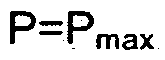 with a starting frequency of ω0. An upper bounding line 401 extends from P=O to P=Pmax with a starting frequency of coo+Δω. Because a constant slope is used by the controller, the response lines are all parallel to and extend between lower bounding line 400 and upper bounding line 401.
[0040] Movement along the lines of constant slope m in response to a transition to island mode depends on whether or not the microgrid is importing power from or
exporting power to the grid. If the system was exporting to the grid before islanding, the resulting frequency of ωexp 412 is greater than the system frequency ω0. For example, if the system was exporting to the grid before islanding, the second microsource may move from the system frequency ωo at second power set point 404 to a third power set point 410 operating at ωexp 412. The first microsource may shift from the system frequency ω0 at first power set point 402 to a fourth power set point 406 at P=O. When the P=O limit is reached, the slope of the characteristic is switched to vertical, as shown by the arrows, to move the first microsource frequency upwards to a fifth power set point 408 operating at ωexp 412. The specific set points, of course, depend on the local demands and operating points of the microsources. A P=O limit may not be reached by either microsource.
[0041] If the system was importing from the grid before islanding, the resulting frequency of ω,mp 420 will be smaller than the system frequency ω0. For example, if the system was importing to the grid before islanding, the first microsource may move from the system frequency ω0 at first power set point 402 to a sixth power set point 414 operating at ω,mp 420. The second microsource may move from the system frequency ω0 at second power set point 404 to a seventh power set point 416 at P= Pmax- When the P=Pmax limit is reached, the slope of the characteristic is switched to vertical, as shown by the arrows, to move the second microsource frequency downwards to an eighth power set point 418 operating at ω,mp 420. The minimum and maximum power limits are enforced by switching the characteristic with constant slope to a vertical steady state characteristic when the minimum or maximum power limit is reached. The specific set points, of course, depend on the local demands and operating points of the microsources. A
limit may not be reached by either microsource.
[0042] With reference to Fig. 5, a graph depicting the relationship between steady state zone power and frequency (F-ω) using a fixed minimum slope method and zone power control is shown in accordance with an exemplary embodiment. Two exemplary microsources are included in the microgrid. The microsources have different power set points. A first microsource has a first flow set point 500. A
second microsource has a second flow set point 502. The slope is fixed at the minimum slope m, but has a reversed sign because of the relation between the microsource output power, P, and the zone power flow, F, which can be derived by inspection of Fig. 3 as F|ine + Psource = Load. F|jne is the power (imported means positive) from the rest of DER system 100, and Psource is the power injected or absorbed by microsource 302. The power injected or absorbed by microsource 302 is assumed to be greater than the minimum power output, Pmjn, of microsource 302 and less than the maximum power output, Pmaχ. of microsource 302. For a microsource capable of power injection only, Pmjn is positive or zero, while a bidirectional device capable of both power injection or power storage may have Pmm < 0. Load is the overall loading level seen by microsource 302.
[0043] During connection with the grid, the flow in the zones tracks the requested values at the system frequency ωo. When the microgrid transfers to island mode, the two microsources readjust the flow depending on the arrangement of the microsources with respect to each other and utility supply 102. When regulating unit power, the relative location of loads and microsources is irrelevant, but when regulating zone power flow, the relative location of loads and microsources is important. For example, with reference to Fig. 6, a first microsource 604 and a second microsource 610 are arranged in series in a single zone. The use of a single zone is for illustrative purposes only. There can be a greater or a lesser number of microsources in a single zone.
[0044] The zone includes a first load 606 and a second load 612 on a local power bus 614 connected by an interface switch 600 to utility supply 102. During a transition to island mode, interface switch 600 opens. As a result, in a zone power control method for the circuit of Fig. 6, a first flow 602 nearest to the utility system is zero in island mode. A second flow 608 may increase to compensate for the first flow 602 transition to zero. Thus, with reference to Fig. 5, first flow 602 moves from the system frequency ω0 at first flow set point 500 to a third flow set point 510 operating at the frequency ωexp 514. Second flow 608 moves from the system frequency ωo at second flow set point 502 to a fourth power set point 512. As a result, in island mode, the system operates at frequency coexP 514 where first flow 602
is zero. Frequency ωexp 514 is larger than the nominal system frequency ω0 because the system was exporting to the grid (|first flow 602| < |second flow 608|), which is the same behavior seen using unit power control.
[0045] With reference to Fig. 7, a first microsource 706 and a second microsource 710 are arranged in parallel in two zones. The use of two zones each with a single microsource is for illustrative purposes only. There can be a greater or a lesser number of microsources in a greater or a lesser number of zones. A first load 708 is located on a first local power bus 714 connected by an interface switch 700 to utility supply 102. A second load 712 is located on a second local power bus 716 connected by interface switch 700 to utility supply 102. A first flow 702 flows through first local power bus 714, and a second flow 704 flows through second local power bus 716. The grid flow is the algebraic sum of first flow 702 and second flow 704. During a transition to island mode, interface switch 700 opens.
[0046] In a zone power control method for the arrangement of Fig. 7, during island mode, the frequency takes the value where the sum of the flows is zero. As a result, as shown on Fig. 5, the frequency in island mode is frequency copar 508 where F1 = - F2. With reference to Fig. 5, first flow 702 moves from the system frequency ω0 at first flow set point 500 to a fifth flow set point 504 operating at the frequency ωpar 508. Second flow 704 moves from the system frequency ω0 at second flow set point 502 to a sixth power set point 506 at the frequency copar 508.
[0047] With reference to Fig. 8a, a microsource 800 is shown in accordance with an exemplary embodiment. Microsource 800 may include an energy storage system 801 , a power generation system 803, a coordination controller 805, and an observer 807. Coordination controller 805 controls the operation of energy storage system 801 and power generation system 803 and the mode of operation of each device. Observer 807 provides characteristic parameters of microsource 800 and of a DER system to which microsource 800 is connected for use by energy storage system 801 , power generation system 803, and coordination controller 805. Microsource 800 and its various components may be implemented in or include hardware, firmware, software, and/or any combination of these methods. Thus, microsource
800 may include circuitry that can implement the processes indicated in the form of hardware, firmware, and/or a processor executing instructions embodied in software.
[0048] With reference to Fig. 8b, microsource 800 connects to a grid through feeder lines 802. Feeder lines 802 extend toward utility supply 102 in a first direction 804 and away from utility supply 102 in a second direction 806. Microsource 800 connects to feeder lines 802 through bus lines 811 which connect with a first transformer 850. A first sensor 813 measures a feeder current 808 through feeder lines 802 and sends the measured feeder current to observer 807. A second sensor 810 measures a feeder bus voltage at the connection point of bus lines 811 with feeder lines 802 and sends the measured feeder bus voltage to observer 807. A third sensor 815 measures an inverter current 809 through bus lines 811 between first transformer 850 and feeder lines 802 and sends the measured inverter current to observer 807. Observer 807 captures local measurements 812 for input to energy storage system 801 , power generation system 803, and coordination controller 805.
[0049] With continuing reference to Fig. 8b, energy storage system 801 is shown in accordance with an exemplary embodiment. Energy storage system 801 may include an inductor 842, an inverter 852, a first voltage regulator 854, a P-ω droop controller 856, and an energy storage device 858. Observer 807 sends droop controller inputs 814 to P- ω droop controller 856. Observer 807 sends first voltage regulator inputs 816 to first voltage regulator 854. Observer 807 sends coordination controller inputs 818 to coordination controller 805. Inverter 852 connects to feeder lines 802 through inductor 842 and first transformer 850. Inverter 852 generates an output voltage at a phase angle of δ. In general, the magnitude of δ is small enough to satisfy the approximation sin(δ) ~ δ. This implies that power is linear relative to δ. Inverter 852 generates an output voltage at a phase angle of δ. Energy storage device 858 connects with inverter 852 through a DC bus 840.
[0050] First voltage regulator 854 assists in decoupling interactions between DER microsources and includes a voltage vs. reactive power droop controller so that, as the reactive power Q generated by inverter 852 becomes more capacitive, a local
voltage set point 826 is reduced. Conversely, as Q becomes more inductive, local voltage set point 826 is increased.
[0051] Coordination controller 805 controls the rate of charge and discharge and the charge levels of energy storage device 858 by setting storage power output limits 834 input to P- ω droop controller 856 based on an energy level 836 received from energy storage device 858. P- ω droop controller 856 provides the P-ω and/or F-ω functions described with reference to Figs. 4 and 5. Coordination controller 805 further receives storage set points 820 and an operational mode 822 as inputs to control the operation of energy storage system 801 and power generation system 803.
[0052] With reference to Fig. 8c, power generation system 803 is shown in accordance with an exemplary embodiment. Power generation system 803 may include a second voltage regulator 860, a P-ω droop governor 862, a prime mover 864, and a generator 866. Generator 866 connects to feeder lines 802 through a second transformer 851. A fourth sensor 817 measures a generator current 819 through bus lines 811 between second transformer 851 and feeder lines 802 and sends the measured generator current to observer 807. Generator 866 may be directly connected to the grid. As a result, second transformer 851 need not be included in microsource 800. For example, if the internal reactance is large enough to achieve the necessary isolation, second transformer 851 is not needed. Prime mover 864 attaches to a rotor shaft of generator 866 to drive generator 866. Typically, the electrical output provided by generator 866 is responsive to the excitation of a field coil in generator 866. Fuel is combusted in prime mover 864 to cause an output shaft to turn at a rotational speed or frequency coshaft, which in turn drives the frequency of the output of generator 866.
[0053] Second voltage regulator 860 assists in decoupling interactions between DER microsources and includes a voltage vs. reactive power droop controller so that, as the reactive power Q generated by generator 866 becomes more capacitive, a local voltage set point 868 is reduced. Conversely, as Q becomes more inductive, local voltage set point 868 is increased. P-ω droop governor 862 provides the P-ω
and/or F-ω functions described with reference to Figs. 4 and 5. P-ω droop governor 862 additionally provides control over prime mover 864. Prime mover 864 can be, for example, an engine, micro turbine, wind turbine, mechanical storage, etc.
[0054] Local measurements 812 to observer 807 may include feeder current 808, the feeder bus voltage, inverter bus current 809, generator bus current 819, three phase reactive power Q injected onto utility supply 102 by generator 866 and energy storage device 858, the injected three phase power P injected onto utility supply 102 by generator 866 and energy storage device 858, the three phase grid power flow F, the angular velocity or frequency of the shaft ωShaft of generator 866, etc. Observer 807 uses electrical measurements of current, voltage, power, energy storage levels, and generator state to calculate data needed by energy storage system 801 , power generation system 803, and coordination controller 805. Observer 807 sends droop governor inputs 878 to P- ω droop governor 862. Observer 807 sends second voltage regulator inputs 870 to second voltage regulator 860. Coordination controller 805 controls the operation of power generation system 803 by setting generator power output limits 838 input to P- ω droop governor 862 based on a generator power received from observer 807.
[0055] With reference to Fig. 9a, a block diagram of first voltage regulator 854 is shown in accordance with an exemplary embodiment. First voltage regulator 854 may include a β block 900, a first summer 902, a second summer 904, and a controller 906. The local voltage set point 826 is input to first voltage regulator 854. A regulated output voltage 824 is output from first voltage "regulator 854 and input to inverter 852. Creating an appropriate regulated output voltage at the terminals of inverter 852 regulates the feeder bus voltage. A plurality of inputs 816 from observer 807 include a storage reactive power Q 908 and feeder bus voltage 910. Storage reactive power Q 908 is input to β block 900, which calculates a modified reactive power 912.
[0056] The modified reactive power 912 is subtracted from local voltage set point 826 in first summer 902 to define a desired local voltage set point 914 based on a droop constant β defined in β block 900. In an exemplary embodiment, β block 900
is implemented to exhibit a voltage vs. reactive current droop as shown with reference to Fig. 12. Droop constant β is the slope of the droop characteristic line 1220. As reactive power Q becomes more inductive, the desired local voltage set point 914 becomes larger than the local voltage set point 826. As reactive power Q becomes more capacitive, the desired local voltage set point 914 becomes smaller than the local voltage set point 826. A feeder bus voltage 910 is compared to the desired local voltage set point 914 in second summer 904. For example, feeder bus voltage 910 is subtracted from the desired local voltage set point 914. The resulting voltage error 916 is input to controller 906 to generate the regulated output voltage 824. In an exemplary embodiment, controller 906 is a proportional-integral (Pl) controller.
[0057] With reference to Fig. 9b, a block diagram of second voltage regulator 860 is shown in accordance with an exemplary embodiment. Second voltage regulator 860 may include a second β block 920, a third summer 922, a fourth summer 924, and a second controller 926. The local voltage set point 868 is input to second voltage regulator 860. Local voltage set point 868 of second voltage regulator 860 may or may not be the same as local voltage set point 826 of first voltage regulator 854. A regulated output voltage 872 is output from second voltage regulator 860 and input to generator 866. Creating an appropriate regulated output voltage at the terminals of generator 866 regulates the feeder bus voltage. A plurality of inputs 870 from observer 807 include a generator reactive power Q 928 and feeder bus voltage 910. Generator reactive power Q 928 is input to second β block 920, which calculates a modified reactive power 932.
[0058] The modified reactive power 932 is subtracted from local voltage set point 868 in third summer 922 to define a desired local voltage set point 934 based on a droop constant β defined in β block 920 as discussed previously with reference to β block 900 of first voltage regulator 854. Feeder bus voltage 910 is compared to the desired local voltage set point 934 in fourth summer 924. For example, feeder bus voltage 910 is subtracted from the desired local voltage set point 934. The resulting voltage error 936 is input to second controller 926 to generate the regulated output voltage 872. In an exemplary embodiment, second controller 926 is a Pl controller.
[0059] Energy storage device 858 normally operates in flow control mode with a F-ω characteristic as shown in Fig. 5. In some situations, energy storage device 858 may operate in unit power control mode with a P-ω characteristic as shown in Fig. 4. In either case, the limits of power from energy storage device 858 are input from coordination controller 805 to P- ω droop controller 856. With reference to Fig. 10, the range of output power, P, available from energy storage device 858 imposes a window 1007 on feeder flow, F, such that P[oad - Pmax < F<"Pioad - Pmin, where P|Oad is the load on the system, and Pmax and Pmin are the limits on energy storage device 858. When charging, Pmjή is negative. A system F-ω0 operating point 1000 is defined for the system frequency ωo. The limits for the feeder flow, F, can be visualized on the F-ω plane as a window whose width 1006 is the difference between Fmιn 1002 and Fmax 1004 which equals the difference between Pmax and Pmjn. The location of the window on the F-axis depends on the value of P|Oad- As P|Oad increases, window 1007 slides to the right on the F-ω plane. Conversely, if the load is reduced, window 1007 slides to the left on the F-ω plane.
[0060] An example flow set point 1008 falls within window 1007. Situations are possible that can result in the flow set point falling outside window 1007. For example, load levels while connected to the grid, an incorrect choice for the flow set point, a change in output power of other microsources, and a transfer to island mode all can cause the flow set point to fall outside window 1007. For example, a first flow set point 1010 falls to the left of window 1007. In this situation, Pmax is exceeded. As another example, a second flow set point 1012 falls to the right of window 1007. In this situation, Pmm is exceeded. To avoid a flow set point falling outside window 1007, when the flow set point is outside window 1007, the controls reset the flow set point to the closest edge of window 1007.
[0061] Similarly, generator 866 can operate in flow control mode with an F-ω characteristic as shown in Fig. 5 or in unit power control mode with a P-ω characteristic as shown in Fig. 4. In either case, the limits of power from generator 866 are input from coordination controller 805 to P- ω droop governor 862. With reference to Fig. 10, the range of output power, P, available from generator 866
imposes window 1007 on feeder flow, F, such that P|Oad - Pmax < F < P|Oad - Pmm, where Pιoad is the load on the system, and Pmax and Pmjn are the power limits of generator 866.
[0062] With reference to Fig. 11a, P- ω droop controller 856 is shown in accordance with an exemplary embodiment. P- ω droop controller 856 may include a first mode switch 1100, a first summer 1102, a first Pl controller 1104, a second summer 1106, a second Pl controller 1108, a third summer 1112, a multiplier 1114, a fourth summer 1116, a fifth summer 1118, and an integrator 1120. A plurality of inputs 814 from observer 807 include a storage power 1132 and a measured power flow 1124. With reference to Figs. 8b and 11a, inputs of P- ω droop controller 856 also include storage power limits 834 from coordination controller 805, a power set point 830, and a frequency set point 832. An inverter phase angle 828 is output from P- ω droop controller 856 to inverter 852.
[0063] With reference to Fig. 11a, P- ω droop controller 856 may be used to provide zone power control or unit power control. As a result, power set point 830 may be P0 or F0. If unit power control is used, a power flow 1148 input to third summer 1112 is three phase power P 1132 output from observer 807 based on inverter current 809 and feeder bus voltage 910. If zone power control is used, power flow 1148 is three phase grid power flow F 1124 output from observer 807 based on feeder current 808 and feeder bus voltage 910. Mode switch 1100 determines which power parameter, three phase power P 11-32 or three phase grid power flow F 1124, is input to third summer 1112. If unit power control is used, the sign of slope m in multiplier block 11 14 is reversed. Three phase power P 1132 is input to first summer 1102 and second summer 1106.
[0064] Power limits 834 include a Psmax set point 1134 of energy storage device 858 and a Psmιn set point 1140 of energy storage device 858. Changing the limits Psmax and Psmin controls the width of window 1007 shown with reference to Fig. 10. Coordination controller 805 controls the charge state of energy storage device 858 through the limits Psmax and PSmm. First summer 1102 compares Psmax set point 1134 with Pmeas 1132 to calculate a first power difference 1136 input to first Pl
controller 1104. For example, first summer 1102 subtracts Pmeas 1132 from Ps013x set point 1134. First Pl controller 1104 controls the maximum power through. a maximum frequency change 1138, Δωmax, that is limited between a minimum frequency and'O Hz. In an exemplary embodiment, the minimum frequency is -1 Hz. Second summer 1106 compares Psmιn set point 1140 with Pmeas 1132 to calculate a second power difference 1142 input to second Pl controller 1108. For example, second summer 1106 subtracts Pmeas 1132 from Psmin set point 1140. Second Pl controller 1108 controls the minimum power through a minimum frequency change 1144, Δωmιn, that is limited between 0 Hz and a maximum frequency. In an exemplary embodiment, the maximum frequency is 1 Hz. Δωmaχ and Δωmin are scaled as radians for input to fifth summer 1118. Maximum frequency change 1138 and minimum frequency change 1144 maintain the flow set point within window 1007. In general, control parameters of the first and second Pl controllers 1104, 1108 are set such that a steady state at a limit is reached in 10-20 cycles.
[0065] Third summer 1112 compares power set point 830 with power flow 1148 to calculate a third power difference 1150 input to multiplier 1114. For example, third summer 1 1 12 subtracts power flow 1148 from power set point 830. Multiplier 1114 multiplies third power difference 1150 by the slope m to determine a frequency change 1152. Depending on the type of power control, frequency change 1152 may be defined as m(F0 - Fmeas) or -m(P0 - Pmeas)- Fourth summer 1116 adds frequency set point 832 to frequency change 1152 to calculate an operating frequency 1154 input to fifth summer 1118. Fifth summer 1118 adds operating frequency 1154 with maximum frequency change 1138 and minimum frequency change 1144 to calculate a requested frequency 1156 input to integrator 1120. The output of the integrator 1120 is inverter phase angle 828, which is rotating in time at frequency ωreq. Inverter phase angle 828 is reset to zero when it exceeds 2π radians. As known to those skilled in the art, energy storage system 801 can be implemented using a fewer or a greater number of elements than those depicted in Figs. 8b, 9a, and 11a. The elements shown are merely exemplary.
[0066] With reference to Fig. 11 b, P-ω droop governor 862 is shown in accordance with an exemplary embodiment. P-ω droop governor 862 may include a
second mode switch block 1160, a first summer 1162, a third proportionalPI controller 1164, a second summer 1166, a fourth Pl controller 1168, a fuel controller block 1170, a third summer 1172, a second multiplier 1174, a fourth summer 1176, a fifth summer 1178, and a sixth summer 1180. A plurality of inputs 878 from observer 807 include a generator power 1182 and measured power flow 1124, and the angular velocity or revolutions per minute of the shaft, coshaft 1186 of generator 866. With reference to Figs. 8c and 11 b, inputs of P-ω droop governor 862-also include power limits 838, a power set point 876, and a frequency set point 874. A fuel command 880 is output from P-ω droop governor 862 to prime mover 864.
[0067] With reference to Fig. 11 b, P-ω droop governor 862 may be used to provide zone power control or unit power control. As a result, power set point 876 may be P0 or F0. If unit power control is used, power flow 1202 is three phase power P 1182 output from observer 807 based on generator bus current 819 and feeder bus voltage 910. If zone power control is used, power flow 1202 is three phase grid power flow F 1124. Second mode switch 1160 determines which power parameter, three phase power P 1182 or three phase grid power flow F 1124, is input to third summer 1172 of P-ω droop governor 862. If unit power control is used, the sign of slope m in second multiplier block 1174 is reversed.
[0068] Three phase power P 1182 is input to first summer 1162 and second summer 1166 of P-ω droop governor 862. Power limits 838 include a Pgmax set point 1 190 of generator 866 and a Pgmjπ set point 1196 of generator 866. Changing the limits Pgmaχ and Pgm,n controls the width of window 1007 shown with reference to Fig. 10. First summer 1162 of P-ω droop governor 862 compares Pgmaχ set point 1190 with three phase power P 1182 to calculate a first power difference 1192 input to third Pl controller 1164. For example, first summer 1162 of P-ω droop governor 862 subtracts three phase power P 1182 from Pgmaχ set point 1190 so that first power difference 1192 is negative if the Pgmaχ set point 1190 is exceeded. Third Pl controller 1164 controls the maximum power through a maximum frequency change 1194, Δωmax, that is limited between a minimum frequency and 0 Hz. In an exemplary embodiment, the minimum frequency is -1 Hz. Second summer 1166 of
P-ω droop governor 862 compares Pgmin set point 1196 with three phase power P 1182 to calculate a second power difference 1198 input to fourth Pl controller 1168. For example, second summer 1166 of P-ω droop governor 862 subtracts three phase power P 1182 from Pgmin set point 1196 so that first power difference 1198 is positive if the Pgmin set point 1196 is exceeded. Fourth Pl controller 1168 controls the minimum power through a minimum frequency change 1200, Δωmin, that is limited between 0 Hz and a maximum frequency. In an exemplary embodiment, the maximum frequency is 1 Hz. Δωmax and Δcomin are scaled as radians for input to fifth summer 1178 of P-ω droop governor 862. In general, control parameters of the third and fourth Pl controllers 1164, 1168 are set such that a steady state at a limit is reached in 10-20 cycles. Maximum frequency change 1194 and minimum frequency change 1200 maintain the flow set point within window 1007.
[0069] Third summer 1112 of P-ω droop governor 862 compares power set point 876 with power flow 1202 to calculate a third power difference 1204 input to second multiplier 1174. For example, third summer 1112 of P-ω droop governor 862 subtracts power flow 1202 from power set point 876. Power set point 876 of P-ω droop governor 862 may be the same or different from power set point 830 of P-ω droop controller 856. Second multiplier 1174 multiplies third power difference 1204 by the slope m to determine a frequency change 1206. Depending on the type of power control, frequency change 1206 may be defined as m(F0 - F) or -m(P0 - P).
[0070] Fourth summer 1176 of P-ω droop governor 862 adds frequency set point 874 to frequency change 1206 to calculate a total frequency 1208 input to fifth summer 1178 of P-ω droop governor 862. Frequency set point 874 of P-ω droop governor 862 may be the same or different from frequency set point 832 of P-ω droop controller 856. Fifth summer 1178 of P-ω droop governor 862 adds total frequency 1208 with maximum frequency change 1194 and minimum frequency change 1200 to calculate a requested shaft speed 1210 input to sixth summer 1180 of P-ω droop governor 862. Sixth summer 1180 of P-ω droop governor 862 compares coshaft 1186 with requested shaft speed 1210 to calculate a shaft rotation error 1212 input to fuel controller 1170. For example, sixth summer 1180 of P-ω
droop governor 862 subtracts ωshaft 1186 from requested shaft speed 121.0 to determine shaft rotation error 1212. The output of fuel controller 1170 is fuel command 880 calculated based on shaft rotation error 1212 and input to prime mover 864. In an exemplary embodiment, fuel controller 1170 is a Pl controller. As known to those skilled in the art, power generation system 803 can be implemented using a fewer or a greater number of elements than those depicted in Figs. 8c, 9b, and 11 b. The elements shown are merely exemplary.
[0071] Microsource 800, which includes a combined generation and storage capability, may have six basic modes of operation denoted here as A, B1 C, D, E, F. Modes A and B are normally used for "peak shaving" during the high load periods of the day. In "peak shaving", the utility provides a preset amount of load and microsource 800 provides for any excess load requirements. In contrast, in "base loading"; microsource 800 provides a preset amount of load and the utility provides for any excess load requirements. In mode A1 generator 866 tracks the load and energy storage device 858 may be set to a fixed output, Ps, which is equal to or less than Ps11n, which is the preferred discharge rate of energy storage device 858. The maximum sustained generator output is Pg PM .
[0072] Mode B is the mirror image of mode A with energy storage device 858 tracking the load and generator 866 providing a constant output power, Pg. In the case of storage, Ps0011 may be set at the maximum rating of inverter 852. In general, generator 866 is operated at the most efficient operating point. In both modes A and B, it is assumed that energy storage device 858 has the energy necessary to operate as required in the modes.
[0073] Mode C is the expected mode used during low loads, (i.e. early morning) where the utility is providing more power than the loads needs. In this case, generator 866 is off and energy storage device 858 takes up any difference with its minimum limit set to the desired charging rate, -Pschg . The maximum limit is set to the maximum possible discharge rate, Ps≠ to allow energy storage device 858 to handle a sudden load increase or loss of the utility while generator 866 comes up to help to meet the load.
[0074] Mode D is used when the feeder transfers to island operation. Limits on both generator 866 and energy storage device 858 may be relaxed to facilitate the transition. Mode E is used when the energy level of energy storage device 858 falls below a minimum reserve value, Es_min_res. Es_min_res is the minimum reserve value of energy that energy storage device 858 should have to be able to provide short-term energy to loads during islanding. Mode E is activated to hold the energy level above Es_min_res. Generator 866 is set at it's maximum power to supply loads and to charge energy storage device 858. Mode F is used when the energy level of energy storage device 858 reaches a maximum reserve value, Es_max_res. Es_max_res is the maximum reserve value of energy that energy storage device 858 should not exceed except during a brief time in island operation (Mode D). Mode F is activated to reduce the storage level of energy storage device 858 to an acceptable level.
[0075] Depending on the value of the energy in energy storage device 858, on the power allocation choice, and on the loading level of microsource 800, coordination controller 805 controls energy storage system 801 and power generation system 803 to operate in one of the six possible modes as summarized below:

[0076] Each mode has specific triggers and rules to move to another mode. As an example, a load profile is shown with reference to Fig. 13 in accordance with an exemplary embodiment in which "peak shaving" is provided by microsource 800. Fig. 13 shows a load curve 1300, for example, covering a 24-hour period. The power
provided by the utility is defined by the F0 set point. For loads less than F0, energy storage device 858 is charging (mode C). For loads greater than F0, energy storage device 858 and generator 866 are providing power to hold the power from the utility to F0. Three different load regions can be defined for which microsource 800 operates in different modes.
[0077] In a first region 1310, the load request is lower than the amount of power F0 imported from the grid. For example, this condition is illustrated in the time interval between a first time 1301 and a second time 1302. In first region 1310, the power in excess of power F0 is used to charge energy storage device 858 allowing the flow of power from the utility to remain constant at F0. The output power of generator 866 is zero and the minimum power limit for the storage is -Pschg . Thus, the time interval between first time 1301 and second time 1302 results in operation in Mode C, in which, energy storage device 858 is charged from the utility, i.e., Pgιmx =
Pg ™ = 0; Ps nux = 0; and Psmn = - Pschg .
[0078] In a second region 1312, the load request is higher than the amount of power F0 imported from the grid with the excess power required to meet the load request less than the maximum output of the generator. For example, this condition is illustrated in the time interval between second time 1302 and a third time 1304 and also between a fourth time 1306 and a fifth time 1308. In second region 1312, the load demand is higher than the power imported from the utility and the shortage of power is provided by generator 866 to allow the power from the utility to remain constant at F0. The output power from energy storage device 858 is zero. Thus, the time intervals between second time 1302 and third time 1304 and between fourth time 1306 and fifth time 1308 results in operation in Mode A, in which, generator 866 tracks the load and energy storage device 858 provides a fixed output power. Thus, Pg m = 0; Pg m = Pg PM : and Ps m = Ps^ = 0.
[0079] In a third region 1314, the load request is higher than the amount of power F0 imported from the grid with the excess power required to meet the load request greater than the maximum output of the generator, Pg PM . For example, this
condition is illustrated in the time interval between third time 1304 and fourth time 1306. In third region 1314, the load demand is larger than the sum of the flow of power coming from the grid F0 and the nominal maximum power limit for generator 866 Pg ΛW . Energy storage device 858 provides the excess power required to satisfy the load demands while maintaining the power coming from the grid to F0. Thus, energy storage device 858 performs the load tracking function. Thus, the time interval between third time 1304 and fourth time 1306 results in operation in Mode B such that Pgma = Pgmu = Pg m ; Ps m = Ps ≠; and Psιmn = 0. Additional load profiles may be used to track load using the combined generation/storage system of microsource 800 based on different operating rules.
[0080] With reference to Fig. 14a, exemplary operations performed by coordination controller 805 in determining a setting of Pg^x are shown based on
Modes A-F. In an operation 1400, a determination is made concerning whether or not energy storage device 858 is charging. If energy storage device 858 is charging, processing continues at an operation 1402. If energy storage device 858 is not charging, processing continues at an operation 1408. In operation 1402, a determination is made concerning whether or not an energy level of energy storage device 858 is less than Es_min_res. If the energy level of energy storage device 858 is less than Es_min_res, processing continues at an operation 1404. If the energy level of energy storage device 858 is not less than Es_min_res, processing continues at an operation 1406. In operation 1404, generator 866 is used to charge energy storage device 858 with Pgπax = Pg Pκl . In operation 1406, generator 866 is switched off and the grid charges energy storage device 858 with Pgx^x = 0.
[0081] In operation 1408, a determination is made concerning whether or not an energy level of energy storage device 858 is greater than Es_max_res. If the energy level of energy storage device 858 is greater than Es_max_res, processing continues at an operation 1410. If the energy level of energy storage device 858 is not greater than Es_max_res, processing continues at an operation 1412. In operation 1410, generator 866 is switched off and the grid discharges energy storage device 858 with Pg mx = 0. In operation 1412, generator 866 can be operated at maximum power
with Pg0011 = Pg pu and energy storage device 858 may be operated to provide "peak shaving".
[0082] With reference to Fig. 14b, exemplary operations performed by coordination controller 805 in determining a setting of Pg^n are shown. In operation 1420, a determination is made concerning whether or not an energy level of energy storage device 858 is less than Es_min_res. If the energy level of energy storage device 858 is less than Es_min_res, processing continues at an operation 1422. If the energy level of energy storage device 858 is not less than Es_min_res, processing continues at an operation 1424. In operation 1422, generator 866 is used to charge energy storage device 858 with Pg ran = Pg PM . In operation 1424, a determination is made concerning whether or not energy storage device 858 is charging. If energy storage device 858 is charging, processing continues at an operation 1426. If energy storage device 858 is not charging, processing continues at an operation 1428. In operation 1426, generator 866 is switched off and the grid charges energy storage device 858 with Pgmn = 0.
[0083] In operation 1428, a determination is made concerning whether or not an energy level of energy storage device 858 is greater than Es_max_res. If the energy level of energy storage device 858 is greater than Es_max_res, processing continues at an operation 1430. If the energy level of energy storage device 858 is not greater than Es_max_res, processing continues at an operation 1432. In operation 1430, generator 866 is switched off and the grid discharges energy storage device 858 with Pg In]n = 0. In operation 1432, generator 866 can be operated at maximum power with Pgnm = Pg PM and energy storage device 858 may be operated to provide "peak shaving".
[0084] With reference to Fig. 14c, exemplary operations performed by coordination controller 805 in determining a setting of Ps00x are shown. In operation
1440, a determination is made concerning whether or not generator 866 is providing a maximum power, Pg m . If generator 866 is providing a maximum power Pg m , processing continues at an operation 1442. If generator 866 is not providing a
maximum power, Pg PM , processing continues at an operation 1448. In operation 1442, a determination is made concerning whether or not an energy level of energy storage device 858 is less than Es_min_res. If the energy level of energy storage device 858 is less than Es_min_res, processing continues at an operation 1446. If the energy level of energy storage device 858 is not less than Es_min_res, processing continues at an operation 1444. In operation 1444, energy storage device 858 is allowed to inject maximum power with Ps1113x = Ps≠ to support "peak shaving". In operation 1446, energy storage device 858 is not allowed to inject power and Psnax = 0.
[0085] In operation 1448, a determination is made concerning whether or not an energy level of energy storage device 858 is greater than Es_max_res. If the energy level of energy storage device 858 is greater than Es_max_res, processing continues at an operation 1452. If the energy level of energy storage device 858 is not greater than Es_max_res, processing continues at an operation 1450. In operation 1450, generator 866 is controlled to provide "base loading" and energy storage device 858 is not allowed to inject power and Psn^x = 0. In operation 1452, energy storage device 858 injects power with Psam = Ps1111n = fixed Ps < Psώs such that generator 866 and energy storage device 858 share the load requirements.
[0086] With reference to Fig. 14d, exemplary operations performed by coordination controller 805 in determining a setting of Psmn are shown. In operation 1460, a determination is made concerning whether or not an energy level of energy storage device 858 is greater than Es_max_res. If the energy level of energy storage device 858 is greater than Es_max_res, processing continues at an operation 1464. If the energy level of energy storage device 858 is not greater than Es_max_res, processing continues at an operation 1462. In operation 1462, energy storage device 858 is allowed to charge with Ps mn = -Ps^ . In operation 1464, energy storage device 858 is prevented from charging such that Psmn = 0.
[0087] With reference to Fig. 15, a logic design 1500 for coordination controller 805 is shown in accordance with an exemplary embodiment. Logic design 1500
includes Ps 1132, Pgaax 1502, Pg 1182, Pspk 1504, and -P.ypt1506 as inputs and pgm 1 19°- pg∞ 1 196' Ps >™ 1 134- Ps™ 1140 as outputs. Ps 1132 is provided as an input to integrator 1514 to form an integrated Ps 1516. Ps 1132 is input to a first block 1520 which determines if Ps<0. Pg 1504 is input to a second block 1524 which determines if Pg= Pg^x ■ Integrated Ps 1516 or Es is input to a third block 1518 which determines if Es<Es_min_res. Es is also input to a fourth block 1522 which determines if Es>Es_max_res. Es is input to a fifth block 1526 which determines if Es=Es_max_res. Logic design 1500 is further comprised of inverters, non-inverting amplifiers, AND gates, and OR gates which provided the functionality discussed with reference to Figs. 14a-14d in setting Pginsx 1190, Pg ran 1196, Ps ^x 1134, Ps mn 1140.
[0088] The foregoing description of exemplary embodiments of the invention have been presented for purposes of illustration and of description. It is not intended to be exhaustive or to limit the invention to the precise form disclosed, and modifications and variations are possible in light of the above teachings or may be acquired from practice of the invention. The embodiments were chosen and described in order to explain the principles of the invention and as practical applications of the invention to enable one skilled in the art to utilize the invention in various embodiments and with various modifications as suited to the particular use contemplated. It is intended that the scope of the invention be defined by the claims appended hereto and their equivalents.
Claims
1. A controller for controlling an energy storage device and a power generation device used in a distributed energy resource, the controller comprising circuitry: to determine a mode of operation for an energy storage device and a power generation device based on an energy level of the energy storage device and on a load to which the energy storage device and the power generation device are operably coupled for power transfer; to determine a first minimum power set point and a first maximum power set point for the energy storage device based on the determined mode of operation and on a storage output power, wherein the storage output power is measured at a first power bus operably coupled to the energy storage device; to determine a second minimum power set point and a second maximum power set point for the power generation device based on the determined mode of operation and on a generation output power, wherein the generation output power is measured at a second power bus operably coupled to the power generation device; to control a first output power of the energy storage device based on the determined first minimum power set point and the determined first maximum power set point; and to control a second output power of the power generation device based on the determined second minimum power set point and the determined second maximum power set point.
2. The controller of claim 1 , wherein controlling the first output power of the energy storage device comprises: calculating a maximum frequency change for an inverter coupled with the energy storage device based on a first comparison between the determined first maximum power set point and the storage output power; calculating a minimum frequency change for the inverter based on a second comparison between the determined first minimum power set point and the storage output power; calculating an operating frequency for the inverter based on a third comparison between a power set point and a measured power flow; calculating a requested frequency for the inverter by combining the calculated maximum frequency change, the calculated minimum frequency change, and the calculated operating frequency; and integrating the calculated requested frequency to determine a phase angle of a voltage of the inverter to control the first output power.
3. The controller of claim 2, wherein the measured power flow is the storage output power.
4. The controller of claim 2, further comprising regulating an output voltage of the inverter using a voltage versus reactive power droop controller.
5. The controller of claim 1 , wherein controlling the second output power of the power generation comprises: calculating a maximum frequency change for the power generation device based on the determined second maximum power set point and the generation output power; calculating a minimum frequency change for the power generation device based on the determined second minimum power set point and the generation output power; calculating an operating frequency for the power generation device based on a third comparison between a power set point and a measured power flow; calculating a requested shaft speed for the power generation device by combining the calculated maximum frequency change, the calculated minimum frequency change, and the calculated operating frequency; calculating a shaft speed adjustment for the power generation device based on a fourth comparison between the calculated requested shaft speed and a measured shaft speed of the power generation device; calculating a fuel command for the power generation device based on the calculated shaft speed adjustment; and adjusting a rotation rate of a shaft of the power generation device based on the calculated fuel command to control the second output power.
6. The controller of claim 5, wherein the measured power flow is the generation output power.
7. The controller of claim 5, further comprising regulating an output voltage of the power generation device using a voltage versus reactive power droop controller.
8. The controller of claim 1 , wherein in a first mode of operation, the determined first minimum power set point is a constant power level, the determined first maximum power set point is the constant power level, the determined second minimum power set point is approximately zero, and the second maximum power set point is determined to provide an excess power level required by the load.
9. The controller of claim 8, wherein the constant power level is a preferred discharge rate of the energy storage device.
10. The controller of claim 1 , wherein in a first mode of operation, the determined second minimum power set point is a constant power level, the determined second maximum power set point is the constant power level, the determined first maximum power set point is a maximum discharge rate of the energy storage device, and the first minimum power set point is determined to provide an excess power level required by the load.
11. The controller of claim 1 , wherein in a first mode of operation, the determined first minimum power set point is a charge rate of the energy storage device and the determined first maximum power set point is a maximum discharge rate of the energy storage device.
12. The controller of claim 11 , wherein the determined second minimum power set point is approximately zero, the determined second maximum power set point is approximately zero, and further wherein the power transfer charges the energy storage device.
13. The controller of claim 1 , wherein in a first mode of operation, the determined first minimum power set point is a maximum charge rate of the energy storage device, the determined first maximum power set point is a maximum discharge rate of the energy storage device, the determined second minimum power set point is approximately zero, and the determined second maximum power set point is a maximum sustained power output of the power generation device.
14. The controller of claim 13, wherein the power transfer is zero.
15. The controller of claim 1 , wherein the energy level of the energy storage device is below a minimum reserve value, and further wherein the determined second minimum power set point is a maximum sustained power output of the power generation device, the determined second maximum power set point is the maximum sustained power output of the power generation device, and the second output power of the power generation device charges the energy storage device.
16. The controller of claim 15, wherein the determined first minimum power set point is a maximum charge rate of the energy storage device, and the determined first maximum power set point is a maximum discharge rate of the energy storage device.
17. The controller of claim 1 , wherein the energy level of the energy storage device is above a maximum reserve value, and further wherein the determined second minimum power set point is approximately zero, the determined second maximum power set point is approximately zero, the determined first minimum power set point is approximately zero, and the determined first maximum power set point is a maximum discharge rate of the energy storage device.
18. A method of controlling an energy storage device and a power generation device used in a distributed energy resource, the method comprising: determining a mode of operation for an energy storage device and a power generation device based on an energy level of the energy storage device and on a load to which the energy storage device and the power generation device are operably coupled for power transfer; determining a first minimum power set point and a first maximum power set point for the energy storage device based on the determined mode of operation and on a storage output power, wherein the storage output power is measured at a first power bus operably coupled to the energy storage device; determining a second minimum power set point and a second maximum power set point for the power generation device based on the determined mode of operation and on a generation output power, wherein the generation output power is measured at a second power bus operably coupled to the power generation device; controlling a first output power of the energy storage device based on the determined first minimum power set point and the determined first maximum power set point; and controlling a second output power of the power generation device based on the determined second minimum power set point and the determined second maximum power set point.
19. A microsource, the microsource comprising: an energy storage device operably coupled for power transfer to a load through a first power bus; a power generation device operably coupled for power transfer to the load through a second power bus; and a controller operably coupled with the energy storage device and the power generation device, the controller including circuitry to determine a mode of operation for the energy storage device and the power generation device based on an energy level of the energy storage device and on the load; to determine a first minimum power set point and a first maximum power set point for the energy storage device based on the determined mode of operation and on a storage output power measured at the first power bus; to determine a second minimum power set point and a second maximum power set point for the power generation device based on the determined mode of operation and on a generation output power measured at the second power bus; to control a first output power of the energy storage device based on the determined first minimum power set point and the determined first maximum power set point; and to control a second output power of the power generation device based on the determined second minimum power set point and the determined second maximum power set point.
Applications Claiming Priority (2)
| Application Number | Priority Date | Filing Date | Title |
|---|---|---|---|
| US11/681,017 | 2007-03-01 | ||
| US11/681,017 US7920942B2 (en) | 2007-03-01 | 2007-03-01 | Control of combined storage and generation in distributed energy resources |
Publications (1)
| Publication Number | Publication Date |
|---|---|
| WO2008109264A1 true WO2008109264A1 (en) | 2008-09-12 |
Family
ID=39539607
Family Applications (1)
| Application Number | Title | Priority Date | Filing Date |
|---|---|---|---|
| PCT/US2008/054572 Ceased WO2008109264A1 (en) | 2007-03-01 | 2008-02-21 | Control of combined storage and generation in distributed energy resources |
Country Status (2)
| Country | Link |
|---|---|
| US (1) | US7920942B2 (en) |
| WO (1) | WO2008109264A1 (en) |
Cited By (6)
| Publication number | Priority date | Publication date | Assignee | Title |
|---|---|---|---|---|
| WO2011134430A1 (en) * | 2010-04-30 | 2011-11-03 | 新奥科技发展有限公司 | System energy efficiency controller, energy efficiency gain device and smart energy service system used for energy utilization |
| EP2463674A1 (en) * | 2010-12-08 | 2012-06-13 | Siemens Aktiengesellschaft | Arrangement and method for testing an electric power generation system |
| CN102621989A (en) * | 2011-01-30 | 2012-08-01 | 中央大学 | Sun tracking method and sun tracking system device |
| EP2562411A3 (en) * | 2011-08-23 | 2014-03-19 | RWE Power Aktiengesellschaft | Power pant with a storage device for the material used to create energy |
| US9182471B2 (en) | 2011-01-27 | 2015-11-10 | National Central University | Sun tracking method and sun tracking system |
| US10008854B2 (en) | 2015-02-19 | 2018-06-26 | Enphase Energy, Inc. | Method and apparatus for time-domain droop control with integrated phasor current control |
Families Citing this family (54)
| Publication number | Priority date | Publication date | Assignee | Title |
|---|---|---|---|---|
| JP5037244B2 (en) * | 2006-07-10 | 2012-09-26 | ハイデルベルガー ドルツクマシーネン アクチエンゲゼルシヤフト | Controlled energy consumption of the electric drive in the machine |
| GB2449427B (en) * | 2007-05-19 | 2012-09-26 | Converteam Technology Ltd | Control methods for the synchronisation and phase shift of the pulse width modulation (PWM) strategy of power converters |
| US7930070B2 (en) * | 2008-09-25 | 2011-04-19 | Kingston Consulting, Inc. | System, method, and module capable of curtailing energy production within congestive grid operating environments |
| WO2010088545A2 (en) * | 2009-01-30 | 2010-08-05 | Board Of Regents, The University Of Texas System | Methods and apparatus for design and control of multi-port power electronic interface for renewable energy sources |
| US8315745B2 (en) | 2009-04-24 | 2012-11-20 | Hunter Defense Technologies, Inc. | Mobile micro-grid power system controller and method |
| US8219256B2 (en) * | 2009-07-14 | 2012-07-10 | Siemens Aktiengesellschaft | Bang-bang controller and control method for variable speed wind turbines during abnormal frequency conditions |
| US8224497B2 (en) * | 2009-08-21 | 2012-07-17 | International Business Machines Corporation | Energy limit in a sliding window in power and heat management |
| KR101038274B1 (en) * | 2010-04-09 | 2011-06-01 | 그리드온(주) | Micropower for Microgrid and its Control Method |
| US8447435B1 (en) * | 2010-04-15 | 2013-05-21 | Science Applications International Corporation | System and method for routing power across multiple microgrids having DC and AC buses |
| US8644997B2 (en) * | 2010-05-10 | 2014-02-04 | Hamilton Sundstrand Corporation | Load sharing architecture for redundant channel controllers |
| KR101713331B1 (en) * | 2010-07-30 | 2017-03-08 | 삼성전자주식회사 | Method and Apparatus for Controlling Energy Supply |
| WO2012034114A2 (en) * | 2010-09-10 | 2012-03-15 | Comverge, Inc. | A method and system for controlling a building load in tandem with a replenishable energy source in order to increase the apparent size of the replenishable energy source |
| GB2490510B (en) * | 2011-05-04 | 2013-10-30 | Rolls Royce Plc | A turbine array and a method of controlling a turbine array during a loss of grid event |
| CN102426663B (en) * | 2011-05-20 | 2014-05-28 | 新奥科技发展有限公司 | Method for controlling universal-energy network by universal-energy current sequence parameter |
| US10879727B1 (en) | 2011-05-26 | 2020-12-29 | James Carl Cooper | Power source load control |
| US11522365B1 (en) * | 2011-05-26 | 2022-12-06 | J. Carl Cooper | Inverter power source load dependent frequency control and load shedding |
| US11183843B1 (en) * | 2011-05-26 | 2021-11-23 | J. Carl Cooper | Power source load control |
| US9728969B2 (en) * | 2011-05-31 | 2017-08-08 | Vestas Wind Systems A/S | Systems and methods for generating an inertial response to a change in the voltage of an electricial grid |
| US10519931B2 (en) | 2011-05-31 | 2019-12-31 | Vestas Wind Systems A/S | Systems and methods for generating an inertial response to a change in the voltage of an electrical grid |
| DE102011078045A1 (en) | 2011-06-24 | 2012-12-27 | Siemens Aktiengesellschaft | Methods and apparatus for allocating energy |
| US10228667B2 (en) | 2011-08-02 | 2019-03-12 | Synaptic Power Inc. | System and a method of controlling a plurality of devices |
| US10935948B2 (en) | 2011-08-02 | 2021-03-02 | Synaptic Power Inc. | System and method for managing interactions between a plurality of devices |
| US8716885B2 (en) | 2011-10-19 | 2014-05-06 | Thomas & Betts International, Inc. | Disconnect switch for distributed energy system |
| US9190871B2 (en) | 2011-10-19 | 2015-11-17 | Thomas & Betts International, Llc | Distributed energy system disconnect switch with mechanical isolation |
| US8946929B2 (en) | 2011-11-04 | 2015-02-03 | Honeywell International Inc. | Method and apparatus for effective utilization of energy storage components within a microgid |
| US9287714B2 (en) * | 2011-11-30 | 2016-03-15 | Michael Ropp | Method and system for island detection and anti-islanding protection in distributed power generation systems |
| US9870593B2 (en) | 2011-12-05 | 2018-01-16 | Hatch Ltd. | System, method and controller for managing and controlling a micro-grid |
| ITTO20120181A1 (en) * | 2012-03-01 | 2013-09-02 | Sisvel Technology Srl | METHOD AND APPARATUS FOR THE MANAGEMENT OF ELECTRICITY PRODUCED LOCALLY FOR SELF-CONSUMPTION AND DISTRIBUTED TO MULTIPLE UTILITIES BELONGING TO ONE OR MORE COMMUNITIES OF UTILITIES |
| US11050249B2 (en) * | 2012-03-23 | 2021-06-29 | Concentric Power, Inc. | Systems and methods for power cogeneration |
| US10169832B2 (en) * | 2013-05-08 | 2019-01-01 | Instant Access Networks, Llc | Method and instrumentation for sustainable energy load flow management system performing as resilient adaptive microgrid system |
| JP6042133B2 (en) * | 2012-08-06 | 2016-12-14 | 京セラ株式会社 | Management system, management method, control device, and power storage device |
| WO2014058571A2 (en) * | 2012-10-08 | 2014-04-17 | Eaton Corporation | Generator dispatching or load shedding control method and system for microgrid applications |
| US10270251B1 (en) * | 2012-10-24 | 2019-04-23 | National Technology & Engineering Solutions Of Sandia, Llc | Emulator apparatus for microgrid testing and design |
| CA2809011C (en) * | 2012-11-06 | 2018-07-17 | Mcmaster University | Adaptive energy management system |
| JP6081178B2 (en) * | 2012-12-14 | 2017-02-15 | 株式会社日立製作所 | Power converter and control method of power converter |
| US20140265559A1 (en) * | 2013-03-15 | 2014-09-18 | Levant Power Corporation | Vehicular high power electrical system |
| US8841787B1 (en) * | 2013-03-15 | 2014-09-23 | Caterpillar Inc. | Generator set adaptive droop control method |
| US20140278699A1 (en) * | 2013-03-15 | 2014-09-18 | Honeywell International Inc. | Modeling energy conversion in systems |
| US9564757B2 (en) | 2013-07-08 | 2017-02-07 | Eaton Corporation | Method and apparatus for optimizing a hybrid power system with respect to long-term characteristics by online optimization, and real-time forecasts, prediction or processing |
| CA2920924A1 (en) * | 2013-09-06 | 2015-03-12 | Opus One Solutions Energy Corp. | Systems and methods for grid operating systems in electric power systems |
| US9471080B2 (en) | 2013-10-21 | 2016-10-18 | Restore Nv | Portfolio managed, demand-side response system |
| US9450516B2 (en) * | 2014-03-05 | 2016-09-20 | National Chung Shan Institute Of Science And Technology | Inverter system for energy-storing microgrid and controlling method thereof |
| US9964978B2 (en) | 2015-04-14 | 2018-05-08 | Princeton Power Systems, Inc. | Control systems for microgrid power inverter and methods thereof |
| JP6702408B2 (en) * | 2016-03-08 | 2020-06-03 | 日本電気株式会社 | Power control device, power control system, power control method, and program |
| US9887655B2 (en) * | 2016-05-31 | 2018-02-06 | Infineon Technologies Ag | Excitation current-limited power generator |
| US10516269B2 (en) | 2016-11-16 | 2019-12-24 | Alliance For Sustainable Energy, Llc | Real time feedback-based optimization of distributed energy resources |
| US10739842B2 (en) | 2017-04-01 | 2020-08-11 | Intel Corporation | Power management and protection |
| US10790682B2 (en) * | 2018-03-30 | 2020-09-29 | Intel Corporation | Hybrid power boost charging with peak power protection |
| EP3821515A4 (en) * | 2018-07-10 | 2022-03-16 | DD Dannar LLC | HYBRID POWER PLANT SYSTEMS AND METHODS |
| CN110620380B (en) * | 2019-09-05 | 2023-06-20 | 深圳供电局有限公司 | Virtual power plant control system |
| US11404907B2 (en) * | 2019-11-25 | 2022-08-02 | Hitachi Energy Switzerland Ag | Distributed voltage control for power networks |
| FI3869682T3 (en) * | 2020-02-24 | 2024-07-10 | Danfoss As | METHOD AND CONTROL DEVICE FOR ADJUSTING A POWER CONVERTER |
| US12166345B2 (en) * | 2020-09-11 | 2024-12-10 | Cummins Power Generation Inc. | Systems and methods for a hybrid power grid |
| US11955797B1 (en) | 2023-02-15 | 2024-04-09 | Zola Electric Labs Inc. | Methods and systems for managing power distribution in an electrical distribution network |
Citations (5)
| Publication number | Priority date | Publication date | Assignee | Title |
|---|---|---|---|---|
| US20020198648A1 (en) * | 1998-01-05 | 2002-12-26 | Mark Gilbreth | Method and system for control of turbogenerator power and temperature |
| US20030039132A1 (en) * | 2001-08-21 | 2003-02-27 | Alfred Engler | Device for equal-rated parallel operation of single-or three-phase voltage sources |
| EP1383224A1 (en) * | 2001-04-27 | 2004-01-21 | Kabushiki Kaisha Kobe Seiko sho | Hybrid construction equipment power control apparatus |
| US20040080165A1 (en) * | 2001-12-31 | 2004-04-29 | Capstone Turbine Corporation | Turbogenerator/motor controller with ancillary energy storage/discharge |
| US20060208574A1 (en) * | 2005-03-18 | 2006-09-21 | Wisconsin Alumni Research Foundation | Control of small distributed energy resources |
Family Cites Families (42)
| Publication number | Priority date | Publication date | Assignee | Title |
|---|---|---|---|---|
| CH584474A5 (en) * | 1975-03-25 | 1977-01-31 | Agie Ag Ind Elektronik | |
| US4315163A (en) * | 1980-09-16 | 1982-02-09 | Frank Bienville | Multipower electrical system for supplying electrical energy to a house or the like |
| US5041959A (en) * | 1990-08-14 | 1991-08-20 | General Electric Company | Control system for a current source converter supplying an AC bus |
| US5536976A (en) * | 1994-03-03 | 1996-07-16 | Gas Research Institute | Multiple service load solid state switching for controlled cogeneration system |
| US5198698A (en) * | 1991-02-11 | 1993-03-30 | Best Power Technology, Inc. | Auxiliary power supply system for providing dc power on demand |
| US5559704A (en) * | 1992-11-23 | 1996-09-24 | General Electric Company | Method to compute horsepower required by an internal combustion engine coupled to an auxiliary alternator |
| US5329222A (en) * | 1992-11-30 | 1994-07-12 | Westinghouse Electric Corporation | Apparatus and method for dynamic voltage restoration of utility distribution networks |
| WO1995020836A1 (en) * | 1994-01-26 | 1995-08-03 | Onan Corporation | Generator power system and method |
| US5614770A (en) * | 1994-06-06 | 1997-03-25 | Helionetics, Inc. | Structure and method for performing active injection mode filtering on an AC power system |
| US5596492A (en) * | 1994-06-14 | 1997-01-21 | Electric Power Research Institute, Inc. | Method and apparatus for de-centralized signal frequency restoration in a distributed UPS system |
| US5710699A (en) * | 1996-05-28 | 1998-01-20 | General Electric Company | Power electronic interface circuits for batteries and ultracapacitors in electric vehicles and battery storage systems |
| US5745356A (en) * | 1996-06-25 | 1998-04-28 | Exide Electronics Corporation | Independent load sharing of AC power systems connected in parallel |
| US5811960A (en) * | 1996-10-02 | 1998-09-22 | United Power Corporation | Battery-less uninterruptable sequel power supply |
| AU707433B2 (en) * | 1996-12-03 | 1999-07-08 | Kabushiki Kaisha Toshiba | Electric power system protection and control system and distributed control system |
| AU8696998A (en) * | 1997-08-08 | 1999-03-01 | Alpha Technologies, Inc. | Electrical generator employing rotary engine |
| JP4076721B2 (en) * | 1997-11-24 | 2008-04-16 | エイチ. ウィルス、ロバート | Isolated power-proof method and apparatus for distributed generation |
| US6347027B1 (en) * | 1997-11-26 | 2002-02-12 | Energyline Systems, Inc. | Method and apparatus for automated reconfiguration of an electric power distribution system with enhanced protection |
| US6219591B1 (en) * | 1998-05-15 | 2001-04-17 | Abb Power T&D Company Inc. | Voltage instability predictor (VIP)—method and system for performing adaptive control to improve voltage stability in power systems |
| TR200003395T2 (en) * | 1998-05-19 | 2001-03-21 | Sure Power Corporation | Energy system. |
| KR100698231B1 (en) * | 1998-10-12 | 2007-03-21 | 산요 덴키 가부시키가이샤 | Uninterruptible power supply |
| JP3792428B2 (en) * | 1999-03-09 | 2006-07-05 | 三菱電機株式会社 | Power system control apparatus and power system control method |
| US6134124A (en) * | 1999-05-12 | 2000-10-17 | Abb Power T&D Company Inc. | Universal distributed-resource interface |
| US6172432B1 (en) * | 1999-06-18 | 2001-01-09 | Gen-Tran Corporation | Automatic transfer switch |
| US6252310B1 (en) * | 1999-07-28 | 2001-06-26 | Nextek Power Systems, Inc. | Balanced modular power management system and method |
| US6249411B1 (en) * | 1999-10-07 | 2001-06-19 | International Business Machines Corporation | Over-voltage protection circuit and method for preventing system shutdown in a power system employing multiple power supplies |
| JP2001119860A (en) * | 1999-10-19 | 2001-04-27 | Toshiba Corp | Power system voltage adjustment method and device |
| US6356471B1 (en) * | 2000-07-10 | 2002-03-12 | Powerware Corporation | Dynamic feedback adaptive control system and method for paralleling electric power sources and an uninterruptible power supply including same |
| US6452289B1 (en) * | 2000-07-10 | 2002-09-17 | Satcon Technology Corporation | Grid-linked power supply |
| US6787933B2 (en) * | 2001-01-10 | 2004-09-07 | Capstone Turbine Corporation | Power generation system having transient ride-through/load-leveling capabilities |
| US6812586B2 (en) * | 2001-01-30 | 2004-11-02 | Capstone Turbine Corporation | Distributed power system |
| US6465910B2 (en) * | 2001-02-13 | 2002-10-15 | Utc Fuel Cells, Llc | System for providing assured power to a critical load |
| US6757590B2 (en) * | 2001-03-15 | 2004-06-29 | Utc Fuel Cells, Llc | Control of multiple fuel cell power plants at a site to provide a distributed resource in a utility grid |
| US6738692B2 (en) * | 2001-06-25 | 2004-05-18 | Sustainable Energy Technologies | Modular, integrated power conversion and energy management system |
| US6703719B1 (en) * | 2002-08-28 | 2004-03-09 | General Electric Company | Systems and methods for managing a battery source associated with a microturbine power generating system |
| US7116010B2 (en) * | 2002-09-17 | 2006-10-03 | Wisconsin Alumni Research Foundation | Control of small distributed energy resources |
| US7042110B2 (en) * | 2003-05-07 | 2006-05-09 | Clipper Windpower Technology, Inc. | Variable speed distributed drive train wind turbine system |
| CA2455689A1 (en) * | 2004-01-23 | 2005-07-23 | Stuart Energy Systems Corporation | System for controlling hydrogen network |
| JP4160919B2 (en) * | 2004-03-24 | 2008-10-08 | シャープ株式会社 | Inverter device |
| JP2005312138A (en) * | 2004-04-19 | 2005-11-04 | Canon Inc | Power controller, power generation system and power system |
| US7274975B2 (en) * | 2005-06-06 | 2007-09-25 | Gridpoint, Inc. | Optimized energy management system |
| US7346462B2 (en) * | 2006-03-29 | 2008-03-18 | General Electric Company | System, method, and article of manufacture for determining parameter values associated with an electrical grid |
| US7590472B2 (en) * | 2006-11-09 | 2009-09-15 | Gridpoint, Inc. | Energy arbitrage by load shifting |
-
2007
- 2007-03-01 US US11/681,017 patent/US7920942B2/en active Active
-
2008
- 2008-02-21 WO PCT/US2008/054572 patent/WO2008109264A1/en not_active Ceased
Patent Citations (5)
| Publication number | Priority date | Publication date | Assignee | Title |
|---|---|---|---|---|
| US20020198648A1 (en) * | 1998-01-05 | 2002-12-26 | Mark Gilbreth | Method and system for control of turbogenerator power and temperature |
| EP1383224A1 (en) * | 2001-04-27 | 2004-01-21 | Kabushiki Kaisha Kobe Seiko sho | Hybrid construction equipment power control apparatus |
| US20030039132A1 (en) * | 2001-08-21 | 2003-02-27 | Alfred Engler | Device for equal-rated parallel operation of single-or three-phase voltage sources |
| US20040080165A1 (en) * | 2001-12-31 | 2004-04-29 | Capstone Turbine Corporation | Turbogenerator/motor controller with ancillary energy storage/discharge |
| US20060208574A1 (en) * | 2005-03-18 | 2006-09-21 | Wisconsin Alumni Research Foundation | Control of small distributed energy resources |
Cited By (10)
| Publication number | Priority date | Publication date | Assignee | Title |
|---|---|---|---|---|
| WO2011134430A1 (en) * | 2010-04-30 | 2011-11-03 | 新奥科技发展有限公司 | System energy efficiency controller, energy efficiency gain device and smart energy service system used for energy utilization |
| US9690275B2 (en) | 2010-04-30 | 2017-06-27 | Enn Science & Technology Development Co., Ltd. | System energy efficiency controller, energy efficiency gain device and smart energy service system used for energy utilization |
| EP2463674A1 (en) * | 2010-12-08 | 2012-06-13 | Siemens Aktiengesellschaft | Arrangement and method for testing an electric power generation system |
| US9182471B2 (en) | 2011-01-27 | 2015-11-10 | National Central University | Sun tracking method and sun tracking system |
| CN102621989A (en) * | 2011-01-30 | 2012-08-01 | 中央大学 | Sun tracking method and sun tracking system device |
| CN102621989B (en) * | 2011-01-30 | 2014-02-12 | 中央大学 | Sun tracking method and solar tracking system device |
| EP2562411A3 (en) * | 2011-08-23 | 2014-03-19 | RWE Power Aktiengesellschaft | Power pant with a storage device for the material used to create energy |
| US10008854B2 (en) | 2015-02-19 | 2018-06-26 | Enphase Energy, Inc. | Method and apparatus for time-domain droop control with integrated phasor current control |
| US10951037B2 (en) | 2015-02-19 | 2021-03-16 | Enphase Energy, Inc. | Method and apparatus for time-domain droop control with integrated phasor current control |
| US11355936B2 (en) | 2015-02-19 | 2022-06-07 | Enphase Energy, Inc. | Method and apparatus for time-domain droop control with integrated phasor current control |
Also Published As
| Publication number | Publication date |
|---|---|
| US20090326724A1 (en) | 2009-12-31 |
| US7920942B2 (en) | 2011-04-05 |
Similar Documents
| Publication | Publication Date | Title |
|---|---|---|
| US7920942B2 (en) | Control of combined storage and generation in distributed energy resources | |
| US7787272B2 (en) | Inverter based storage in dynamic distribution systems including distributed energy resources | |
| US7715950B2 (en) | Non-inverter based distributed energy resource for use in a dynamic distribution system | |
| Mao et al. | Decentralized coordination power control for islanding microgrid based on PV/BES-VSG | |
| Tielens et al. | Grid inertia and frequency control in power systems with high penetration of renewables | |
| RU2611725C2 (en) | Electricity supply setting, equipped with means of energy storage, and control method of such facility | |
| Satpathy et al. | Control scheme for a stand-alone wind energy conversion system | |
| Braun | Reactive power supply by distributed generators | |
| EP2715904B1 (en) | System and method for integrating and managing demand/response between alternative energy sources, grid power, and loads | |
| US10554047B2 (en) | Control method of an electric microgrid | |
| US20230187942A1 (en) | Method for operating a power supply plant, and power supply plant | |
| CN117081177B (en) | A power control method for microgrid operation of hydropower main regulating unit in island mode | |
| Borsche et al. | A new frequency control reserve framework based on energy-constrained units | |
| CN114567002A (en) | Energy storage double-fed wind generating set and synchronous generator cooperative frequency modulation control method | |
| US20150028675A1 (en) | Electrical power system and method for operating an electrical power system | |
| CN116885733A (en) | A power system optimization operation method and device based on inertia demand assessment | |
| Pourebrahim et al. | Overview of energy storage systems for wind power integration | |
| US20140306537A1 (en) | Power Management System and Method for Optimizing Fuel Consumption | |
| WO2017089402A1 (en) | Hybrid power system including gensets and renewable energy resources, and method of control | |
| Prajapati et al. | Intelligent Frequency Regulation under a Deregulated Control System Using Distributed Energy Storage Systems | |
| Hu et al. | Modeling of frequency and power control in an autonomous power system with wind turbines and diesel generation units | |
| CN116529982A (en) | Operating a wind turbine in off-grid independent mode | |
| Bhuvaneswari et al. | Hybrid wind–diesel energy systems | |
| US20260121412A1 (en) | Grid power response with optimally sized storage | |
| Rapizza et al. | Innovative Strategies for Upward Frequency Regulation Provision by Renewables and Batteries |
Legal Events
| Date | Code | Title | Description |
|---|---|---|---|
| 121 | Ep: the epo has been informed by wipo that ep was designated in this application |
Ref document number: 08730385 Country of ref document: EP Kind code of ref document: A1 |
|
| NENP | Non-entry into the national phase |
Ref country code: DE |
|
| 122 | Ep: pct application non-entry in european phase |
Ref document number: 08730385 Country of ref document: EP Kind code of ref document: A1 |