WO2008123393A1 - ポリ塩化ビフェニル類の抽出方法 - Google Patents
ポリ塩化ビフェニル類の抽出方法 Download PDFInfo
- Publication number
- WO2008123393A1 WO2008123393A1 PCT/JP2008/056004 JP2008056004W WO2008123393A1 WO 2008123393 A1 WO2008123393 A1 WO 2008123393A1 JP 2008056004 W JP2008056004 W JP 2008056004W WO 2008123393 A1 WO2008123393 A1 WO 2008123393A1
- Authority
- WO
- WIPO (PCT)
- Prior art keywords
- column
- silica gel
- layer
- gel layer
- polychlorinated biphenyls
- Prior art date
- Legal status (The legal status is an assumption and is not a legal conclusion. Google has not performed a legal analysis and makes no representation as to the accuracy of the status listed.)
- Ceased
Links
Classifications
-
- G—PHYSICS
- G01—MEASURING; TESTING
- G01N—INVESTIGATING OR ANALYSING MATERIALS BY DETERMINING THEIR CHEMICAL OR PHYSICAL PROPERTIES
- G01N1/00—Sampling; Preparing specimens for investigation
- G01N1/28—Preparing specimens for investigation including physical details of (bio-)chemical methods covered elsewhere, e.g. G01N33/50, C12Q
- G01N1/40—Concentrating samples
- G01N1/4055—Concentrating samples by solubility techniques
-
- B—PERFORMING OPERATIONS; TRANSPORTING
- B01—PHYSICAL OR CHEMICAL PROCESSES OR APPARATUS IN GENERAL
- B01D—SEPARATION
- B01D15/00—Separating processes involving the treatment of liquids with solid sorbents; Apparatus therefor
-
- B—PERFORMING OPERATIONS; TRANSPORTING
- B01—PHYSICAL OR CHEMICAL PROCESSES OR APPARATUS IN GENERAL
- B01J—CHEMICAL OR PHYSICAL PROCESSES, e.g. CATALYSIS OR COLLOID CHEMISTRY; THEIR RELEVANT APPARATUS
- B01J20/00—Solid sorbent compositions or filter aid compositions; Sorbents for chromatography; Processes for preparing, regenerating or reactivating thereof
- B01J20/02—Solid sorbent compositions or filter aid compositions; Sorbents for chromatography; Processes for preparing, regenerating or reactivating thereof comprising inorganic material
- B01J20/10—Solid sorbent compositions or filter aid compositions; Sorbents for chromatography; Processes for preparing, regenerating or reactivating thereof comprising inorganic material comprising silica or silicate
- B01J20/103—Solid sorbent compositions or filter aid compositions; Sorbents for chromatography; Processes for preparing, regenerating or reactivating thereof comprising inorganic material comprising silica or silicate comprising silica
-
- B—PERFORMING OPERATIONS; TRANSPORTING
- B01—PHYSICAL OR CHEMICAL PROCESSES OR APPARATUS IN GENERAL
- B01J—CHEMICAL OR PHYSICAL PROCESSES, e.g. CATALYSIS OR COLLOID CHEMISTRY; THEIR RELEVANT APPARATUS
- B01J20/00—Solid sorbent compositions or filter aid compositions; Sorbents for chromatography; Processes for preparing, regenerating or reactivating thereof
- B01J20/30—Processes for preparing, regenerating, or reactivating
- B01J20/32—Impregnating or coating ; Solid sorbent compositions obtained from processes involving impregnating or coating
- B01J20/3202—Impregnating or coating ; Solid sorbent compositions obtained from processes involving impregnating or coating characterised by the carrier, support or substrate used for impregnation or coating
- B01J20/3204—Inorganic carriers, supports or substrates
-
- B—PERFORMING OPERATIONS; TRANSPORTING
- B01—PHYSICAL OR CHEMICAL PROCESSES OR APPARATUS IN GENERAL
- B01J—CHEMICAL OR PHYSICAL PROCESSES, e.g. CATALYSIS OR COLLOID CHEMISTRY; THEIR RELEVANT APPARATUS
- B01J20/00—Solid sorbent compositions or filter aid compositions; Sorbents for chromatography; Processes for preparing, regenerating or reactivating thereof
- B01J20/30—Processes for preparing, regenerating, or reactivating
- B01J20/32—Impregnating or coating ; Solid sorbent compositions obtained from processes involving impregnating or coating
- B01J20/3231—Impregnating or coating ; Solid sorbent compositions obtained from processes involving impregnating or coating characterised by the coating or impregnating layer
- B01J20/3234—Inorganic material layers
- B01J20/3236—Inorganic material layers containing metal, other than zeolites, e.g. oxides, hydroxides, sulphides or salts
-
- G—PHYSICS
- G01—MEASURING; TESTING
- G01N—INVESTIGATING OR ANALYSING MATERIALS BY DETERMINING THEIR CHEMICAL OR PHYSICAL PROPERTIES
- G01N1/00—Sampling; Preparing specimens for investigation
- G01N1/28—Preparing specimens for investigation including physical details of (bio-)chemical methods covered elsewhere, e.g. G01N33/50, C12Q
- G01N1/40—Concentrating samples
- G01N1/4022—Concentrating samples by thermal techniques; Phase changes
-
- G—PHYSICS
- G01—MEASURING; TESTING
- G01N—INVESTIGATING OR ANALYSING MATERIALS BY DETERMINING THEIR CHEMICAL OR PHYSICAL PROPERTIES
- G01N27/00—Investigating or analysing materials by the use of electric, electrochemical, or magnetic means
- G01N27/62—Investigating or analysing materials by the use of electric, electrochemical, or magnetic means by investigating the ionisation of gases, e.g. aerosols; by investigating electric discharges, e.g. emission of cathode
- G01N27/622—Ion mobility spectrometry
- G01N27/623—Ion mobility spectrometry combined with mass spectrometry
-
- G—PHYSICS
- G01—MEASURING; TESTING
- G01N—INVESTIGATING OR ANALYSING MATERIALS BY DETERMINING THEIR CHEMICAL OR PHYSICAL PROPERTIES
- G01N30/00—Investigating or analysing materials by separation into components using adsorption, absorption or similar phenomena or using ion-exchange, e.g. chromatography or field flow fractionation
- G01N30/02—Column chromatography
- G01N30/04—Preparation or injection of sample to be analysed
- G01N30/06—Preparation
-
- G—PHYSICS
- G01—MEASURING; TESTING
- G01N—INVESTIGATING OR ANALYSING MATERIALS BY DETERMINING THEIR CHEMICAL OR PHYSICAL PROPERTIES
- G01N30/00—Investigating or analysing materials by separation into components using adsorption, absorption or similar phenomena or using ion-exchange, e.g. chromatography or field flow fractionation
- G01N30/02—Column chromatography
- G01N30/26—Conditioning of the fluid carrier; Flow patterns
- G01N30/38—Flow patterns
- G01N30/46—Flow patterns using more than one column
- G01N30/461—Flow patterns using more than one column with serial coupling of separation columns
- G01N30/462—Flow patterns using more than one column with serial coupling of separation columns with different eluents or with eluents in different states
-
- G—PHYSICS
- G01—MEASURING; TESTING
- G01N—INVESTIGATING OR ANALYSING MATERIALS BY DETERMINING THEIR CHEMICAL OR PHYSICAL PROPERTIES
- G01N30/00—Investigating or analysing materials by separation into components using adsorption, absorption or similar phenomena or using ion-exchange, e.g. chromatography or field flow fractionation
- G01N30/02—Column chromatography
- G01N30/60—Construction of the column
- G01N30/6034—Construction of the column joining multiple columns
- G01N30/6039—Construction of the column joining multiple columns in series
-
- G—PHYSICS
- G01—MEASURING; TESTING
- G01N—INVESTIGATING OR ANALYSING MATERIALS BY DETERMINING THEIR CHEMICAL OR PHYSICAL PROPERTIES
- G01N30/00—Investigating or analysing materials by separation into components using adsorption, absorption or similar phenomena or using ion-exchange, e.g. chromatography or field flow fractionation
- G01N30/02—Column chromatography
- G01N30/88—Integrated analysis systems specially adapted therefor, not covered by a single one of the groups G01N30/04 - G01N30/86
-
- G—PHYSICS
- G01—MEASURING; TESTING
- G01N—INVESTIGATING OR ANALYSING MATERIALS BY DETERMINING THEIR CHEMICAL OR PHYSICAL PROPERTIES
- G01N33/00—Investigating or analysing materials by specific methods not covered by groups G01N1/00 - G01N31/00
- G01N33/26—Oils; Viscous liquids; Paints; Inks
- G01N33/28—Oils, i.e. hydrocarbon liquids
- G01N33/2835—Specific substances contained in the oils or fuels
-
- G—PHYSICS
- G01—MEASURING; TESTING
- G01N—INVESTIGATING OR ANALYSING MATERIALS BY DETERMINING THEIR CHEMICAL OR PHYSICAL PROPERTIES
- G01N1/00—Sampling; Preparing specimens for investigation
- G01N1/28—Preparing specimens for investigation including physical details of (bio-)chemical methods covered elsewhere, e.g. G01N33/50, C12Q
- G01N1/40—Concentrating samples
- G01N1/4055—Concentrating samples by solubility techniques
- G01N2001/4061—Solvent extraction
-
- G—PHYSICS
- G01—MEASURING; TESTING
- G01N—INVESTIGATING OR ANALYSING MATERIALS BY DETERMINING THEIR CHEMICAL OR PHYSICAL PROPERTIES
- G01N30/00—Investigating or analysing materials by separation into components using adsorption, absorption or similar phenomena or using ion-exchange, e.g. chromatography or field flow fractionation
- G01N30/02—Column chromatography
- G01N30/88—Integrated analysis systems specially adapted therefor, not covered by a single one of the groups G01N30/04 - G01N30/86
- G01N2030/8809—Integrated analysis systems specially adapted therefor, not covered by a single one of the groups G01N30/04 - G01N30/86 analysis specially adapted for the sample
- G01N2030/884—Integrated analysis systems specially adapted therefor, not covered by a single one of the groups G01N30/04 - G01N30/86 analysis specially adapted for the sample organic compounds
- G01N2030/8845—Integrated analysis systems specially adapted therefor, not covered by a single one of the groups G01N30/04 - G01N30/86 analysis specially adapted for the sample organic compounds involving halogenated organic compounds
-
- G—PHYSICS
- G01—MEASURING; TESTING
- G01N—INVESTIGATING OR ANALYSING MATERIALS BY DETERMINING THEIR CHEMICAL OR PHYSICAL PROPERTIES
- G01N30/00—Investigating or analysing materials by separation into components using adsorption, absorption or similar phenomena or using ion-exchange, e.g. chromatography or field flow fractionation
- G01N30/02—Column chromatography
- G01N30/88—Integrated analysis systems specially adapted therefor, not covered by a single one of the groups G01N30/04 - G01N30/86
- G01N2030/8809—Integrated analysis systems specially adapted therefor, not covered by a single one of the groups G01N30/04 - G01N30/86 analysis specially adapted for the sample
- G01N2030/884—Integrated analysis systems specially adapted therefor, not covered by a single one of the groups G01N30/04 - G01N30/86 analysis specially adapted for the sample organic compounds
- G01N2030/8854—Integrated analysis systems specially adapted therefor, not covered by a single one of the groups G01N30/04 - G01N30/86 analysis specially adapted for the sample organic compounds involving hydrocarbons
-
- Y—GENERAL TAGGING OF NEW TECHNOLOGICAL DEVELOPMENTS; GENERAL TAGGING OF CROSS-SECTIONAL TECHNOLOGIES SPANNING OVER SEVERAL SECTIONS OF THE IPC; TECHNICAL SUBJECTS COVERED BY FORMER USPC CROSS-REFERENCE ART COLLECTIONS [XRACs] AND DIGESTS
- Y10—TECHNICAL SUBJECTS COVERED BY FORMER USPC
- Y10T—TECHNICAL SUBJECTS COVERED BY FORMER US CLASSIFICATION
- Y10T436/00—Chemistry: analytical and immunological testing
- Y10T436/25—Chemistry: analytical and immunological testing including sample preparation
- Y10T436/25375—Liberation or purification of sample or separation of material from a sample [e.g., filtering, centrifuging, etc.]
- Y10T436/255—Liberation or purification of sample or separation of material from a sample [e.g., filtering, centrifuging, etc.] including use of a solid sorbent, semipermeable membrane, or liquid extraction
Definitions
- the present invention relates to a method for extracting polychlorinated biphenyls, and more particularly, to a method for extracting polychlorinated biphenyls from an oily liquid containing polychlorinated biphenyls.
- PCBs mineral oils containing polyphenyl chlorides
- electrical insulation oils containing PCBs, etc. used in the past have a concern of causing environmental pollution in the treatment process, so electrical equipment manufacturers or operators themselves or waste disposal operators For example, it has been stored for a long time until now.
- PCB wastes that are required to be treated under the Special Measures Law for PCBs are electrical insulating oils that were originally manufactured and used before the manufacture and use of PCBs was prohibited. It was assumed that it was limited to those that had been stored. However, because of the discovery of PCBs that appear to have been mixed in the manufacturing process from electrical insulating oils manufactured after the use of PCBs was banned, transformers currently in use, etc. Some of the electrical insulating oil used in electrical equipment in this area may fall under the category of PCB waste subject to the PCB Special Measures Law. Therefore, existing electrical equipment is Therefore, it is determined whether or not the electrical insulating oil used in the product falls under the category of PCB waste subject to the same law (including those containing PCBs of 0.5 mg / kg or more). There is an urgent need to make a decision (this is called PCB screening).
- Whether a sample collected from a judgment object such as electrical insulating oil contains a certain concentration of PCBs is usually determined by gas chromatography / mass spectrometry (GC / MS) or gas-mouth-matograph electron capture detection ( Since the determination is based on the result of analysis using a highly sensitive analyzer such as the GC / ECD method, the sample needs to be highly pre-treated to remove interfering components that affect the analysis result. Such pretreatment is usually performed according to the method described in Appendix 2 “Examination Methods for Specially Controlled General Waste and Specially Controlled Industrial Waste” of the Ministry of Health, Welfare Notification No. 192 (hereinafter referred to as “official law”). ”).
- JISK 0311 Metal for measuring dioxins in exhaust gas
- An object of the present invention is to enable extraction of PCBs in a short time by a simple operation from an oily liquid such as an electrical insulating oil containing PCBs. Disclosure of the invention
- the present invention relates to a method for extracting polychlorinated biphenyls from an oily liquid containing polychlorinated biphenyls, the extraction method comprising adding an oily liquid to a sulfuric acid silica gel layer, Maintaining the added silicic acid sulfate gel layer at a temperature of at least 35 ° C. for a predetermined time and then cooling it to room temperature, and adding an aliphatic hydrocarbon solvent to the sulfuric acid silica gel layer cooled to room temperature for 8 hours.
- Supplying the aliphatic hydrocarbon solvent that has passed through the sulfuric acid silica gel layer to the silver nitrate silica gel layer, and supplying the aliphatic hydrocarbon solvent that has passed through the silver nitrate silica gel layer to the alumina layer to pass therethrough A step of supplying a hydrophobic solvent capable of dissolving polychlorinated bibiphenyls to the alumina layer, and a step of passing the hydrophobic solvent that has passed through the alumina layer. And a step of holding.
- the sulfuric acid silica gel layer to which the oily liquid is added is maintained for a predetermined time in a state heated to at least 35 ° C, it is mainly an aromatic component other than polychlorinated biphenyls contained in the oily liquid.
- Group compounds are rapidly decomposed by reaction with the sulfuric acid silica gel layer. This decomposition product is retained in the silica gel sulfate layer together with the polybiphenyl chlorides.
- an aliphatic hydrocarbon solvent is supplied to the silica sulfate gel layer cooled to room temperature, the aliphatic hydrocarbon solvent passes through the sulfuric acid gel layer and is supplied to the silver nitrate gel layer. Siri passes through the gel layer.
- part of the polychlorinated biphenyls and decomposition products retained in the sulfuric acid silica gel layer are dissolved in the aliphatic hydrocarbon solvent supplied to the sulfuric acid silica gel layer and supplied from the sulfuric acid silica gel layer to the silver nitrate silica gel layer.
- the A part of the decomposition product contained in the aliphatic hydrocarbon solvent supplied to the silver nitrate silica gel layer is adsorbed and retained by the silver nitrate silica gel layer.
- polychlorinated biphenyls contained in the aliphatic hydrocarbon solvent supplied to the silver nitrate silica gel layer pass through the silver nitrate silica gel layer in a state dissolved in the aliphatic hydrocarbon solvent.
- an aliphatic hydrocarbon solvent that has passed through the silver nitrate silica gel layer that is, an aliphatic hydrocarbon solvent in which polyvinyl chloride is dissolved, is supplied to the alumina layer and allowed to pass through, it dissolves in the aliphatic hydrocarbon solvent.
- Polychlorinated biphenyls are trapped in the alumina layer, and impure components other than polychlorinated biphenyls remaining in the aliphatic hydrocarbon solvent (when the oily liquid is an electrical insulating oil made of mineral oil) (Mainly paraffins) pass through the alumina layer together with the aliphatic hydrocarbon solvent without being trapped in the alumina layer. Then, when a hydrophobic solvent is supplied and passed through the alumina layer through which the aliphatic hydrocarbon solvent has passed, the polychlorinated biphenyls trapped in the alumina layer are dissolved in the hydrophobic solvent and become alumina. Extracted from the layer and secured as a hydrophobic solvent solution.
- polychlorinated biphenyls can be extracted in a short time from an oily liquid containing polychlorinated biphenyls by a simple operation.
- the silica gel silica gel layer, the silver nitrate silica gel layer, and the alumina layer are not particularly limited in use, and may be used by being packed in a column or arranged in an appropriate filter. Although it may be used, it is usually preferable to use it in a column.
- a column that is packed with a silica gel silica gel layer, a silver nitrate silica gel layer, and an alumina layer is preferable, for example, in which a silica sulfate gel layer and a silver nitrate gel layer are stacked and packed in the first column.
- the alumina layer is filled in a second force ram that can be attached to and detached from the silver nitrate silica gel layer side of the first force ram.
- the supply direction of the hydrophobic solvent to the alumina layer can be arbitrarily set. That is, the method of supplying the hydrophobic solvent to the alumina layer may be set to be the same as the passing direction of the aliphatic hydrocarbon solvent, or may be set to the opposite direction to the passing direction. However, when the alumina layer is packed in the second column of the first column and the second force ram as described above, the direction of passage of the aliphatic hydrocarbon solvent is opposite to the alumina layer. Supply hydrophobic solvent to It is preferable to pass through. In the alumina layer, polybiphenyl chlorides are mainly captured at the end of the supply side of the aliphatic hydrocarbon solvent.
- the hydrophobic solvent solution of polychlorinated biphenyls obtained by this extraction method can be a small amount that can be easily applied in the degradation treatment (detoxification treatment) of polychlorinated biphenyls and various analyses.
- the aliphatic hydrocarbon solvent is supplied to and passed through the metal hydrous salt silica gel layer.
- the process of making it contain further.
- the extraction rate (recovery rate) of polychlorinated biphenyls with a small number of chlorines can be increased.
- the extraction rate (recovery rate) of biphenyls can be further increased.
- a preferable metal hydrate salt silica gel layer used here is, for example, a copper hydrate salt silica gel layer.
- the aliphatic hydrocarbon solvent in the process until the aliphatic hydrocarbon solvent that has passed through the sulfuric acid silica gel layer is supplied to the alumina layer A, the aliphatic hydrocarbon solvent can be supplied to and passed through the carbon material layer.
- the carbon material layer is preferably a layer made of dullite.
- the extraction method using a carbon material layer impurities such as polychlorinated naphthalenes contained in the oily liquid can be captured and removed by the carbon material layer, so that polychlorinated biphenyls can be removed from the oily liquid. It can be extracted with high purity. Therefore, the extraction method using the carbon material layer is particularly effective in the case of extracting polychlorinated bichlors from an oily liquid further containing polychlorinated naphthalenes, for example, electrical insulating oil composed of mineral oil.
- a hydrocarbon solvent having a boiling point equal to or higher than the heating temperature of the sulfuric acid silica gel layer and capable of dissolving the oil liquid can be added to the silica gel layer A together with the oil liquid.
- the oily liquid is diluted with the hydrocarbon solvent, the contact efficiency between the oily liquid and the silica sulfate gel layer is improved, and the reaction efficiency is increased. For this reason, in the silica gel layer, it is contained in the oily liquid in a shorter time.
- Impure components other than polychlorinated biphenyls, especially aromatic compounds, can be decomposed, and the time required for extraction of polychlorinated biphenyls can be shortened.
- the extraction method of the present invention preferably further includes a step of removing the aliphatic hydrocarbon solvent remaining in the alumina layer before supplying the hydrophobic solvent to the alumina layer. In this way, an aliphatic hydrocarbon solvent and a higher-purity extract with less impure components dissolved therein, that is, a hydrophobic solvent solution of polychlorinated biphenyls, can be obtained. The resulting hydrophobic solvent solution is further reduced.
- the extraction method of the present invention it is usually preferable to supply a hydrophobic solvent to the alumina layer while heating the alumina layer to at least 35 ° C. In this way, since the polybiphenyl chlorides trapped in the alumina layer are extracted with a smaller amount of the hydrophobic solvent, the resulting amount of the resulting polychlorinated biphenyls in the hydrophobic solvent is further reduced.
- the present invention according to another aspect relates to a method for measuring polychlorinated biphenyls contained in an oily liquid containing polychlorinated biphenyls.
- a sample collected from an oily liquid is added to the silica gel layer, and the silica gel layer to which the sample is added is heated to at least 35 ° C for a predetermined time and then cooled to room temperature.
- the method includes a step of securing a hydrophobic solvent that has passed through the alumina layer, and a step of analyzing the secured hydrophobic solvent by a gas chromatography method.
- a silica sulfate gel layer to which a sample collected from an oily liquid is added is maintained at a temperature of at least 35 ° C for a predetermined time, an impure component other than polychlorinated bifuninyls contained in the sample (oily liquid)
- an electrically insulating oil composed of mineral oil aromatic compounds are mainly decomposed quickly by reaction with the sulfuric acid silica gel layer.
- This decomposition product is a combination of poly (biphenyl chloride) and silica sulfate. Retained in the gel layer.
- the aliphatic hydrocarbon solvent is supplied to the sulfuric acid silica gel layer cooled to room temperature
- the aliphatic hydrocarbon solvent is supplied to the silver nitrate silica gel layer through the sulfuric acid silica gel layer and passes through the silver nitrate silica gel layer.
- part of the polychlorinated biphenyls and decomposition products retained in the sulfuric acid silica gel layer are dissolved in the aliphatic hydrocarbon solvent supplied to the sulfuric acid silica gel layer and supplied from the sulfuric acid silica gel layer to the silver nitrate silica gel layer.
- an aliphatic hydrocarbon solvent that has passed through the silver nitrate silica gel layer that is, an aliphatic hydrocarbon solvent in which polyvinyl chloride is dissolved
- an aliphatic hydrocarbon solvent in which polyvinyl chloride is dissolved dissolves in the aliphatic hydrocarbon solvent.
- Polychlorinated biphenyls are trapped in the alumina layer, and impure components other than polychlorinated biphenyls remaining in the aliphatic hydrocarbon solvent (electrical insulating oil whose mineral liquid is mineral oil) In this case, mainly paraffins) are not trapped in the alumina layer and pass through the alumina layer together with the aliphatic hydrocarbon solvent.
- hydrophobic solvent solution of polychlorinated biphenyls can be applied to an analysis by a gas chromatography method as it is or by concentrating as appropriate.
- the measurement method of the present invention can prepare an analysis sample of polychlorinated biphenyls in a short time from a sample of an oily liquid containing polychlorinated biphenyls by a simple operation. Polychlorinated biphenyls in liquid can be measured quickly by gas chromatography.
- the silica gel sulfate layer, the silver nitrate silica gel layer and the alumina layer are usually packed in a column.
- a sulfuric acid silica gel layer and a silver nitrate silica gel layer are laminated and filled in the first force ram, and the alumina layer is a second force ram that can be attached to and detached from the silver nitrate silica gel layer side of the first force ram. Filled in ing.
- a hydrophobic solvent is supplied to the alumina layer in a direction opposite to the direction of passage of the aliphatic hydrocarbon solvent and allowed to pass therethrough.
- polyphenyl chlorides are trapped mainly at the end of the supply side of the aliphatic hydrocarbon solvent.
- the hydrophobic solvent solution of polychlorinated biphenyls obtained by this measurement method becomes a small amount of analytical sample suitable for analysis by the gas chromatography method. Therefore, it can be easily applied to analysis by gas chromatography.
- This measurement method can be modified in the same manner as the extraction method described above. That is, before supplying the aliphatic hydrocarbon solvent that has passed through the sulfate silica gel layer to the silver nitrate silica gel layer, supplying the aliphatic hydrocarbon solvent to the metal hydrated silica gel layer, for example, the copper hydrated silica gel layer, and passing it through. May further be included. Further, in the process until the aliphatic hydrocarbon solvent that has passed through the sulfated silica gel layer is supplied to the alumina layer, the aliphatic hydrocarbon solvent is supplied to and passed through the carbon material layer, for example, a layer made of graphite.
- Such a measurement method using a carbon material layer is particularly suitable for measuring polychlorinated biphenyls contained in an oily liquid further containing polychlorinated naphthalenes, for example, an electrical insulating oil made of mineral oil. It is effective for.
- a hydrocarbon solvent having a boiling point equal to or higher than the heating temperature of the sulfuric acid silica gel layer and capable of dissolving the oily liquid can be added to the silica gel layer together with the oily liquid.
- the step of removing the aliphatic hydrocarbon solvent remaining in the alumina layer may be further included before supplying the hydrophobic solvent.
- the hydrophobic solvent can be supplied to the alumina layer while heating the alumina layer to at least 35 ° C.
- the gas chromatography method used in the measurement method of the present invention is suitable for the measurement of a trace amount of polychlorinated biphenyls, and is usually one of a gas chromatograph mass spectrometry method and a gas chromatograph electron capture detection method.
- the present invention according to still another aspect relates to a column used for extracting polychlorinated biphenyls from an oily liquid containing polychlorinated biphenyls.
- This column is detachable from one end to the other end of the first force ram, filled with a silica gel silica layer, metal hydrated silica gel layer, and silver nitrate silica gel layer in this order from one end to the other.
- a second column packed with an alumina layer.
- the first column is preferably further filled with a carbon material layer at an arbitrary position from the sulfuric acid silica gel layer to the other end.
- this carbon material layer is preferably filled between the sulfuric acid silica gel layer and the metal hydrate salt silica gel layer.
- a column according to another aspect of the present invention is also used for extracting polychlorinated biphenyls from an oily liquid containing polychlorinated biphenyls, and includes a sulfated silica gel layer, a metal hydrate A first column in which a silica gel layer and a silver nitrate silica gel layer are packed in this order, a second column in which an alumina layer is packed, and a third column in which a carbon material layer is packed are provided. The third column removably connects the end of the first column on the silver nitrate force gel layer side and one end of the second column.
- the extraction rate (recovery rate) of polychlorinated biphenyls can be increased.
- the measurement accuracy of polychlorinated biphenyls can be increased.
- a column according to still another aspect of the present invention is used for purifying oily liquid in the process of extracting polychlorinated biphenyls from oily liquid containing polychlorinated biphenyls. From one end to the other, a silica gel silica layer, a metal hydrated silica gel layer, and a silver nitrate silica gel layer are packed in this order.
- This column is preferably further filled with a carbon material layer at an arbitrary position from the sulfuric acid silica gel layer to the other end.
- the carbon material layer is preferably filled between the sulfuric acid silica gel layer and the metal hydrate salt silica gel layer.
- Such a column for purifying an oily liquid containing polychlorinated biphenyls is used for carrying out the extraction method or the measuring method of the present invention.
- the extraction rate (recovery rate) can be increased, and the measurement accuracy of polychlorinated biphenyls can be increased.
- the present invention according to still another aspect relates to a treating agent for purifying an oily liquid in the process of extracting polychlorinated biphenyls from an oily liquid containing polychlorinated biphenyls. It consists of metal hydrated silica gel.
- this treating agent is used in the extraction method or measuring method or column of the present invention, the extraction rate (recovery rate) of polychlorinated biphenyls having a small number of chlorines can be increased, so that polychlorinated biphenyls from oily liquids can be obtained.
- the overall extraction rate (recovery rate) can be increased, and the measurement accuracy of polychlorinated biphenyls contained in oily liquids can be increased.
- FIG. 1 is a schematic view of an example of a column that can be used in the method for extracting PCBs according to the present invention.
- FIG. 2 is a diagram showing one step of the extraction operation using the column.
- FIG. 3 is a diagram showing another step of the extraction operation using the column.
- FIG. 4 is a diagram showing still another process of the extraction operation using the column.
- FIG. 5 is a diagram showing still another process of the extraction operation using the column.
- FIG. 6 is a partial schematic diagram of another example of a column that can be used in the method for extracting PCBs according to the present invention.
- FIG. 7 is a partial schematic view of still another example of a column that can be used in the method for extracting PCBs according to the present invention.
- FIG. 8 is a partial schematic view of still another example of a column that can be used in the method for extracting PCBs according to the present invention.
- FIG. 9 is a partial schematic view of still another example of a column that can be used in the method for extracting PCBs according to the present invention.
- FIG. 10 is a partial schematic view of another example of columns that can be used in the method for extracting PCBs according to the present invention.
- FIG. 1 is a partial schematic view of another example.
- FIG. 12 is a schematic view of another example of columns that can be used in the method for extracting PCBs according to the present invention.
- Figure 13 shows the comparison example 4 with ⁇ [scale 0. / 111] ⁇ This is a chromatogram of the monitor channel of the standard material for mass calibration, which was observed when the three-method analysis was performed.
- the method for extracting polychlorinated biphenyls (PCBs) relates to a method for extracting PCBs from an oily liquid containing PCBs.
- oily liquids containing PCBs include electrical insulating oils used in electrical equipment such as transformers and capacitors, waste organic solvents containing PCBs produced in chemical experiments and chemical factories, and for analysis. Extracts obtained by extracting PCBs from a sample containing PCBs with an organic solvent. Examples include decomposition solutions and cleaning solutions generated at PCB decomposition facilities.
- Electrical insulating oil is usually composed of mineral oil mainly composed of relatively high boiling point paraffin, naphthene, or aromatic compound obtained by rectifying petroleum, and it is necessary to improve electrical insulation.
- PCBs may be included when PCBs are added for the purpose or when PCBs are mixed in during the manufacturing process.
- PCBs are those containing a homologue having a chlorine number in the range of 1 to 10 PCBs contained in the electrical insulating oil as described above are usually those having a chlorine number of 2-8.
- the column 1 mainly includes a first column 10, a second column 20, and a connecting member 30 for connecting both the columns 10 0 and 20.
- the first column 10 is formed in a cylindrical shape in which the outer diameter and inner diameter of the lower end portion 10 a are reduced, and the upper end portion and the lower end portion have openings 11 and 12 respectively. Yes.
- the first column 10 is formed using, for example, glass or plastic having solvent resistance and heat resistance, and is filled with multilayer silica gel 13 inside.
- Multilayer silica gel 13 is a laminate of upper layer 14 and lower layer 15.
- the upper layer 14 is a silica gel layer filled with sulfuric acid silica gel, and the sulfuric acid silica gel used here is prepared by uniformly adding concentrated sulfuric acid to the silica gel surface.
- the packing density of the sulfuric acid silica gel is not particularly limited, but is usually preferably set to 0.3 to 1. I gZcm 3 , and is preferably 0.5 to 1.0 gZc m 3. It is more preferable to set to.
- the lower layer 15 is filled with silver nitrate silica gel, that is, a silver nitrate silica gel layer.
- the silver nitrate silica gel used here removes water by heating under reduced pressure after uniformly adding an aqueous solution of silver nitrate to the silica gel surface. It was prepared.
- the packing density of the silver nitrate silica gel is not particularly limited, but it is usually preferable to set the packing density to 0.3 to 0.8 g / cm 3 , and 0.4 to 0.7. It is more preferable to set to gZc m 3 .
- silver nitrate silica gel prepared using the aqueous solution is different from the metal hydrated silica gel described later.
- the ratio of the upper layer 14 to the lower layer 15 is preferably set to 1.0 to 50 times the weight ratio of silica gel sulfate to the silver nitrate silica gel, and set to 3.0 to 30 times. More preferably. If the weight ratio of sulfuric acid silica gel exceeds 50 times, the ratio of silver nitrate silica gel will be small, and the refining of electrical insulating oil by adsorption may be insufficient. Conversely, when the weight ratio of the silica sulfate gel is less than 1.0 times, the refining of the electrical insulating oil by the decomposition action may be insufficient.
- the second column 20 is formed in a cylindrical shape whose outer diameter and inner diameter are set to be substantially the same as the lower end portion 10a of the first column 10, and has opening portions 21 and 22 at the upper end portion and the lower end portion, respectively. is doing.
- the second column 20 is formed using, for example, glass or plastic having solvent resistance and heat resistance, and is filled with a layer filled with alumina, that is, an alumina layer 23.
- the alumina used in the alumina layer 23 is not particularly limited as long as it can adsorb PCBs, and may be any of basic alumina, neutral alumina, and acidic alumina. In addition, as alumina, various Can be used.
- the packing density of alumina in the alumina layer 23 is not particularly limited, but it is usually preferably set to 0.5 to 1.2 gZcm 3, and 0.8 to 1.1 g / cm 3. It is more preferable to set to.
- the connecting member 30 is a cylindrical member capable of inserting the lower end portion 10a of the first column 10 and the upper end portion of the second column 20 and is a material that is stable against various solvents, particularly hydrocarbon solvents. For example, it is formed using a plastic having solvent resistance and heat resistance.
- the connecting member 30 removably connects the lower end portion 10 a of the first column 10 and the upper end portion of the second column 20. Therefore, in the column 1 composed of the first column 10 and the second column 20, the alumina layer 23 portion can be separated from the upper layer 14 and the lower layer 15 independently.
- the size of the column 1 can be appropriately set according to the purpose of extracting PCBs from the oily liquid described later.
- the purpose of pretreatment is to extract PCBs from an oily liquid in order to measure the concentration of PCBs contained in the oily liquid
- a small or trace amount of the sample is collected from the oily liquid and extracted according to the present invention. Since it is sufficient to apply the method, column 1 can be set to be small accordingly.
- PCBs are extracted from oily liquids and PCBs are decomposed (detoxified) in this extract, it is necessary to process a relatively large amount of oily liquids.
- Column 1 can be set to a large size depending on the amount of oily liquid to be processed.
- the size is preferably an inner diameter of 10 to 2 Omm and a length of 30 to 11 Omm
- the size of the second column 20 alumina
- the size of the portion that can be filled with the layer 23 is preferably an inner diameter of 2.0 to: L O. Omm and a length of 10 to 20 Omm.
- the first heating device 40 is arranged around the upper layer 14 of the first column 10, and the suction device is provided at the lower end of the second column 20. 5 Place 0.
- the first heating device 40 is a heater, a Peltier element, etc., for heating the entire upper layer 14 to a required temperature.
- the suction device 50 includes a container 51 that can hermetically accommodate the lower end of the second column 20, and a pump 52 that decompresses the inside of the container 51.
- a solvent container 53 for receiving an aliphatic hydrocarbon solvent to be described later that passes through the column 1 is arranged.
- a small or trace amount sample (usually about 1.0 to 500 mg) is taken from the oily liquid, and this sample is added to the upper layer 14 from the opening 11 at the upper end of the first column 10.
- the first heating device 40 is operated and the upper layer 14 is heated and maintained for a predetermined time.
- the added sample is held in the upper layer 14 of the first column 10.
- impurities other than PCBs, particularly aromatic compounds, contained in the sample react with the silica gel of the upper layer 14 and are quickly decomposed.
- the decomposition product of this reaction is captured in the upper layer 14 and held in the first column 10.
- the heating temperature of the upper layer 14 is set to at least 35 ° C., preferably 50 ° C. or higher, more preferably 60 ° C. or higher.
- the upper limit of the heating temperature is not particularly limited, but is usually about 90 ° C.
- the heating time of the upper layer 14 is usually preferably set to 10 minutes to 8 hours. If the heating time is less than 10 minutes, the above-mentioned impurities contained in the sample will not be decomposed sufficiently, and the final extract may contain impurities other than PCBs. .
- the sample is added to the upper layer 14 of the first column 10 and the upper layer 14 sample, that is, It is preferable to add a hydrocarbon solvent capable of dissolving the oily liquid.
- a hydrocarbon solvent capable of dissolving the oily liquid.
- the hydrocarbon solvents available here are usually aliphatic saturated hydrocarbon solvents having 5 to 8 carbon atoms, such as n-pentane, n-hexane, n-heptane, n-octane, isooctane. And cyclohexane.
- the hydrocarbon solvent is usually added immediately after the sample is added to the upper layer 14 of the first column 10 or may be added to the sample in advance.
- the upper layer 14 heated for a predetermined time in the above-described process is removed from the first heating device 40 after the heating is completed, or the first heating device 40 is turned off and left as it is. Cool down to room temperature (usually about 10 to 30 ° C).
- the first reservoir 60 for supplying the solvent to the first force ram 10 is attached to the opening 11 on the upper end side of the first column 10.
- An aliphatic hydrocarbon solvent is stored in the reservoir 60.
- the pump 52 is operated, the inside of the container 51 is depressurized, and the aliphatic hydrocarbon solvent stored in the first reservoir 60 is gradually and gradually supplied into the first column 10.
- the aliphatic hydrocarbon solvent supplied from the first reservoir 60 into the first power ram 10 is supplied to the upper layer 14, passes through the upper layer 14, and is supplied to the lower layer 15. 1 Go through 5. Then, the aliphatic hydrocarbon solvent that has passed through the lower layer 15 flows from the opening 21 to the second column 20 through the connecting member 30 from the opening 12 of the first column 10. At this time, the PCBs retained in the upper layer 14 are dissolved in the aliphatic hydrocarbon solvent, and flow into the second column 20 through the lower layer 15 together with the aliphatic hydrocarbon solvent.
- the aliphatic hydrocarbon solvent that has flowed into the second ram 20 is supplied to the alumina layer 23 in the second column 20, passes through this layer, is discharged from the opening 22, and is stored in the container 51.
- the solvent container 5 3 is received.
- the aliphatic coal from the first column 10 6 PCBs dissolved in the hydrogen fluoride solvent are captured by the alumina layer 23 and retained in the second column 20.
- PCBs are easily captured by the alumina layer 23, they are mainly held near the opening 21 at the upper end in the second column 20.
- paraffins and the like which are impure components other than aromatic compounds contained in the sample, dissolve in the aliphatic hydrocarbon solvent from the first reservoir 60 and pass through the alumina layer 23 together with the aliphatic hydrocarbon solvent. And received by the solvent container 53.
- the aliphatic hydrocarbon solvent used in this step is capable of dissolving PCBs held in the first column 10 and is usually an aliphatic saturated hydrocarbon solvent having 5 to 8 carbon atoms, for example, N-pentane, n-hexane, n-heptane, n-octane, isooctane, and cyclohexane. In particular, n- ⁇ xan is preferred.
- the amount of the aliphatic hydrocarbon solvent stored in the first reservoir 60 that is, the total amount of the aliphatic hydrocarbon solvent supplied to the first column 10 is usually preferably set to 10 to 120 ml. .
- the supply rate of the aliphatic hydrocarbon solvent from the first reservoir 60 is normally set to 0.2 to 5.0 ml / min by adjusting the reduced pressure state in the container 51 by the pump 52. Is preferred.
- the connecting member 30 is removed to separate the second column 20 and the first column 10, and a second heating device 70 is disposed around the second force ram 20 as shown in FIG. To do.
- the second heating device 70 used here is the same as the first heating device 40.
- the pump 52 is operated while the second heating ram 20 is heated to about 35 to 90 ° C. by the second heating device 70, and nitrogen is introduced into the second column 20 from the opening 21 at the upper end.
- Supply inert gas such as gas or air.
- the solvent such as the aliphatic hydrocarbon solvent remaining in the second column 20 is discharged together with the inert gas from the opening 22 at the lower end of the second force ram 20, and from the alumina layer 23.
- Solvents such as group hydrocarbon solvents are removed.
- the alumina layer 23 in the second column 20 is dried.
- the second column 20 is removed from the suction device 50, and the upper and lower sides of the second column 20 are inverted together with the second heating device 70.
- a second reservoir 80 for supplying the solvent to the opening 22 moved to the upper end side of the second force ram 20 by reversal is mounted, and this second reservoir 80 A predetermined amount of a hydrophobic solvent is supplied inside. 7
- the hydrophobic solvent supplied to the second reserver 80 flows naturally from the second reserver 80 into the second force ram 20 by its own weight, is supplied to the alumina layer 23, and passes through the alumina layer 23. And discharged from the opening 21 moved to the lower end side of the second column 20.
- the hydrophobic solvent from the second reservoir 80 dissolves the PCBs captured by the alumina layer 23 and is discharged from the opening 21 together with the PCBs. Therefore, if the hydrophobic solvent discharged from the opening 21 is secured, a hydrophobic solvent solution for PCBs, that is, an extraction solution for the target PCBs can be obtained.
- the PCBs are mainly captured in the vicinity of the opening 2 1 side of the alumina layer 2 3, the substantially total amount of the PCBs captured by the alumina layer 2 3 is the second column 2 0 It is in a state of being mainly dissolved in the hydrophobic solvent in the first flow part discharged from the water.
- the target PCB extract can be obtained simply by securing the hydrophobic solvent in the initial flow portion discharged from the opening 21. Since this extract is composed of the above-described initial flow portion with a small amount, the amount becomes small that can be easily used in the analysis operation described later. Also, the PCB extract obtained here is obtained by removing the aliphatic hydrocarbon solvent from the alumina layer 23 and then supplying the hydrophobic solvent to the second column 20. An aliphatic hydrocarbon solvent and a high-purity extract with little contamination by impure components dissolved in it.
- the extraction method according to the present embodiment it is usually possible to obtain the above-described extract in a short time of about 2 to 10 hours from the work start process (sample addition process to the first column 10). it can.
- the second column 20 is preferably supplied with a hydrophobic solvent while being heated by the second heating device 70.
- the heating temperature of the second column 20 is usually preferably set so that the temperature of the alumina layer 23 is at least 35 ° C., more preferably 60 ° C. or higher.
- the upper limit of the heating temperature is not particularly limited, but is usually about 90 ° C.
- the hydrophobic solvent used in this extraction process can dissolve PCBs.
- toluene, toluene and an aliphatic hydrocarbon solvent for example, n-pentane, n-xane, n-heptane, n-octane, isooctane, cyclohexane, etc.
- organochlorine solvents eg, dichloromethane, trichloromethane, tetrachloromethane, etc.
- aliphatic hydrocarbon solvents eg, n-pentane, n-xane, n-heptane, n-octane, isooctane, cyclohexane
- toluene which can extract PCBs from the alumina layer 23 in a smaller amount, is preferable.
- the extraction liquid obtained in the above extraction operation is used as an analytical sample and analyzed by gas chromatography.
- Gas chromatography can be carried out using gas chromatography equipped with various detectors, but usually gas chromatography / mass spectrometry (GC / MS method) or gas chromatography with good sensitivity to PCBs.
- GC / MS method gas chromatography / mass spectrometry
- the electron capture detection method is preferred.
- PCBs contained in analytical samples can be quantified in units of isomers and homologs, so more knowledge can be obtained from the analysis results.
- the extract obtained in the above-described extraction operation can be concentrated and used as necessary for analysis by a gas chromatography method.
- the above-described embodiment can be modified as follows, for example.
- the first column 10 is constituted by a single force ram, and the upper layer 14 made of a silica sulfate gel and the lower layer 15 made of a silver nitrate gel are contained therein.
- the first force ram 10 is separated into an upper column 100a and a lower column 100b, which are arranged one above the other. It may be detachably connected by a connecting member 100 c similar to the connecting member 30.
- the upper column 100 a is filled with silica gel sulfate to form the upper layer 14, and the lower column 100 b is filled with silver nitrate silica gel to form the lower layer 15.
- the first 9 Heat only the upper column 100 a with the heating device 40.
- the aliphatic hydrocarbon solvent that has passed through the upper layer 14 made of the silica gel silica gel layer is supplied to the lower layer 15 made of the silver nitrate silica gel, but passed through the upper layer 14.
- the aliphatic hydrocarbon solvent can be supplied to and passed through the metal hydrate salt silica gel layer before being supplied to the lower layer 15.
- an intermediate layer 16 made of metal hydrated silica gel is disposed between the upper layer 14 and the lower layer 15. Can be implemented.
- the metal hydrated silica gel used in the intermediate layer 16 can be prepared by uniformly adding an aqueous solution of a metal hydrate to the surface of the silica gel and then removing the water by heating under reduced pressure.
- the metal hydrate used here is a metal salt compound having hydrated water, for example, copper sulfate hydrate such as copper sulfate pentahydrate, copper nitrate hydrate such as copper nitrate trihydrate, etc.
- Calcium nitrate hydrates such as calcium nitrate tetrahydrate, and iron nitrate (III) hydrates such as iron nitrate ( ⁇ ) nonahydrate.
- copper hydrates such as copper sulfate pentahydrate and copper nitrate trihydrate are preferred.
- the packing density of the metal hydrated silica gel is usually preferably set to 0.3 to 0.8 g / cm 3, and preferably set to 0.4 to 0.7 gZ cm 3 . More preferred. If this packing density is less than 0.3 g / cm 3 , it may be difficult to obtain the effects described below by using metal hydrated silica gel. Conversely, if it exceeds 0.8 g / cm 3 , the rate of chromatographic development of PCBs in the intermediate layer 16 will be slow, so a large amount of aliphatic hydrocarbon solvent may be required for the extraction operation described above. There is sex.
- the amount of the metal hydrated silica gel used in the intermediate layer 16 is preferably set to 0.3 to 4.0 times by weight with respect to the silver nitrate silica gel forming the lower layer 15. It is more preferable to set 5 times.
- the weight ratio of the metal hydrated silica gel is less than 0.3 times, it may be difficult to obtain the effects described below by using the metal hydrated silica gel.
- it exceeds 4.0 times the chromatography development rate of PCBs in the intermediate layer 16 will be slow, so a large amount of aliphatic hydrocarbon solvent may be required in the extraction operation described above. .
- the aliphatic hydrocarbon solvent that has passed through the upper layer 14 made of silica gel sulfate is supplied to the intermediate layer 16 and passes through the intermediate layer 16.
- the lower layer 15 made of silver nitrate silica gel.
- some of the impure components contained in the aliphatic hydrocarbon solvent from the upper layer 14, particularly the electron donating substance, are bonded to the metal hydrate silica gel of the intermediate layer 16 and removed.
- the electron donating substances contained in the aliphatic hydrocarbon solvent from the upper layer 14 are PCBs that bind to silver nitrate silica gel and have a low number of chlorines (hereinafter sometimes referred to as “low chlorine PCBs”), especially Adsorbents of PCBs with two chlorines (hereinafter sometimes referred to as “dichlorine PCBs”) may be formed.
- low chlorine PCBs especially Adsorbents of PCBs with two chlorines
- the low chlorine contained in the aliphatic hydrocarbon solvent is supplied.
- PCBs are adsorbed on the lower layer 15 and removed from the aliphatic hydrocarbon solvent, which may reduce the extraction rate (recovery rate) of low-chlorine PCBs.
- the electron donating substance contained in the aliphatic hydrocarbon solvent from the upper layer 14 is removed by the intermediate layer 16 made of the metal hydrated silica gel, it is made of the silver nitrate silica gel.
- the intermediate layer 16 made of the metal hydrated silica gel it is made of the silver nitrate silica gel.
- the lower layer 15 formation of adsorbents of low chlorine PCBs is suppressed.
- the PCBs contained in the aliphatic hydrocarbon solvent from the upper layer 14 pass through the lower layer 15 made of nitric acid silica gel including the low chlorine PCBs, and the alumina layer 2 3 of the second column 20 stably. Supplied to.
- the extraction rate (recovery rate) of low-chlorine PCBs especially the extraction rate (recovery rate) of dichlorinated PCBs, can be increased.
- the overall extraction rate (recovery rate) of PCBs contained in electrical insulating oil can be increased.
- the first column 10 is composed of a single column, and the upper layer 14, the intermediate layer 16 and the lower layer 15 are laminated in multiple layers as an example.
- the first column 10 with the layer 16 can also be modified.
- the first column 10 is separated into an upper column 1 0 0 a and a lower column 1 0 0 b arranged above and below, and both columns are the same as the connecting member 30 described above. It is also possible to detachably connect the connecting member 1 0 0 c.
- the first column 10 is composed of the upper column 14 in which the upper column 10 0 a is filled with silica gel sulfate and the metal content.
- the intermediate layer 16 filled with hydrated silica gel is formed in multiple layers, and the lower column 10 0 0 b is filled with silver nitrate silica gel to form the lower layer 15.
- the PCBs are extracted from the oily liquid using such a first column 10, only the upper layer 14 portion of the upper ram 10 100 a is heated by the first heating device 40.
- the first column 10 that can be used in this modification example includes an upper column 1 0 0 a, a middle column 1 0 0 d, and a lower column 1 0 0 b arranged vertically.
- the same connection as the above-mentioned connecting member 30 between the upper column 1 0 0 a and the middle column 1 0 0 d and between the middle column 1 0 0 d and the lower column 1 0 0 b It may be detachably connected by the member 100c.
- the upper force ram 100 a is filled with a silica gel and an upper layer 14 is formed.
- Layer 16 is formed, and lower column 100 b is filled with silver nitrate silica gel to form lower layer 15.
- first heating device 40 When extracting PCBs from an oily liquid using such a first column 10, only the upper column 100 0 a is heated by the first heating device 40.
- the aliphatic hydrocarbon solvent that has passed through the silica sulfate gel layer is the carbon material layer in the process until it is supplied to the alumina layer. Can also be passed through.
- the carbon material layer is arranged between the upper layer 14 made of silica gel sulfate and the lower layer 15 made of silver nitrate silica gel or between the lower layer 15 and the alumina layer 2 3 in the first column 10 of the column 1.
- a carbon material layer is placed at an arbitrary position from the upper layer 14 of the first force ram 10 to the lower end 10 a. be able to. That is, the carbon material layer can be disposed between the upper layer 14 and the intermediate layer 16, between the intermediate layer 16 and the lower layer 15, or on the lower end 10 a side of the lower layer 15.
- the carbon material layer is preferably disposed at a position close to the upper layer 14 because the effects described later are easily obtained.
- An example of a preferable column 1 with a carbon material layer is a multilayer silica gel 13 of a first column 10 consisting of a single column, as shown in FIG. Material layer 17 is arranged.
- Another example of a preferable column 1 with a carbon material layer is a single column consisting of a top layer 14, an intermediate layer 16 and a lower layer 15 as shown in Fig. 12.
- a third column 25 is arranged between one end of the second column 20.
- one end of the third column 25 is connected to the end of the first column 10 on the lower layer 15 side using a connecting member 100 c similar to the connecting member 30 described above, and the other end is connected to the third column 25.
- a similar connecting member 100 c is used to connect to one end of the second column 20.
- the carbon material forming the carbon material layer used in this modification is activated carbon or graphite, preferably in the form of particles that can increase the contact area with the aliphatic hydrocarbon solvent that passes through the carbon material layer. belongs to.
- Oily liquids containing PCBs may contain polychlorinated naphthalenes (PCNs) that are similar in structure and molecular weight to PCBs.
- PCNs are dissolved in aliphatic hydrocarbon solvents together with PCBs, and pass through the upper layer 14 and the lower layer 15 and pass through the intermediate layer 16 when applicable, and are captured by the alumina layer 23, and are hydrophobic to the alumina layer 23. May be extracted with a hydrophobic solvent together with PCBs. For this reason, PC.Ns hinder the extraction of PCBs from oily liquids with high purity.
- the carbon material layer is an aliphatic hydrocarbon solvent in which PCBs and PCNs are dissolved.
- the PCNs are selectively captured from the PCN and the PCNs are separated from the aliphatic hydrocarbon solvent. Therefore, the extraction method of this modification using a carbon material layer can extract PCBs with high purity even when the oily liquid contains PCNs together with PCBs.
- the intermediate layer 16 and the carbon material layer 17 are used when the upper layer 14 and the lower layer 15 are used in the above-described embodiments.
- a layer made of ordinary silica gel a layer of cotton, which is made of glass that is stable against PCBs and aliphatic hydrocarbon solvents, or plastic that is resistant to solvents and heat. It can also be arranged.
- the cotton-like layer can also be disposed above the upper layer 14, below the lower layer 15, or below the carbon material layer 17.
- the force for detachably connecting the columns such as between the first column 10 and the second column 20 by the connecting member 30 or the connecting member 100 c.
- Other means can be used to connect the columns.
- a rubbing portion may be provided at the coupling portion of the columns, and the columns may be detachably coupled by connecting the rubbing portions.
- the suction device 50 is provided at the lower end of the second force ram 20, and the aliphatic hydrocarbon solvent stored in the first reservoir 60 is sucked by the suction device 50.
- the aliphatic hydrocarbon solvent in the first reservoir 60 may be allowed to flow down naturally to the first column 10 without using the suction device 50. it can.
- the aliphatic hydrocarbon solvent can also be supplied to the first column 10 using a constant volume pump such as a syringe pump or a pressurizing device. Further, the aliphatic hydrocarbon solvent can be supplied to the first force ram 10 by manual operation using a supply device such as a pipette.
- the hydrophobic solvent supplied to the second reservoir 80 is naturally supplied to the second column 20 by its own weight, but the hydrophobic solvent is a syringe pump or the like. It is also possible to supply to the second column 20 using a metering pump or pressurizing apparatus.
- the second column 20 is separated from the first column 10 when the inert gas or the hydrophobic solvent is supplied to the second force ram 20.
- An inert gas or hydrophobic solvent may be set to be supplied to the second column 20 without separating 20 from the first column 10. This can be realized, for example, by connecting the first column 10 and the second column 20 using a connecting device having a flow path switching valve.
- the flow path switching valve used in this case has an inert gas inlet and a hydrophobic solvent outlet, and a flow path for communicating the first column 10 and the second force ram 20, It has a flow path for connecting the inert gas inlet and the second column 20 and a flow path for connecting the second column 20 and the hydrophobic solvent outlet.
- Supply of aliphatic hydrocarbon solvent from the first column 10 to the second column 20 introduction of inert gas from the inert gas inlet to the second column 20, and hydrophobicity supplied to the second column 20 It is possible to select either discharge from the discharge port of the soluble solvent.
- the electrical insulating oils A, B, C and D used in the following examples and comparative examples are as follows. Of these, electrical insulation oils A, B, and C were confirmed to be substantially free of PCNs by analysis using the GC / ECD method. / ECD analysis confirmed that it contains PCNs.
- the concentration of PCNs in Electrical Insulating Oil D is equivalent to approximately 24 mg / kg in terms of PCB concentration conversion, which is not compared with the concentration of coexisting PCBs. Always high concentration.
- the first force ram and the second force ram used in Examples 1 to 14 and Comparative Examples 1 to 6 below are as follows.
- alumina (trade name “MP A l um ina B— Su pe” by M.P Biomedicals, Inc. in a column of 2.5 mm ID and 100 mm length. r I ”) filled.
- the first power ram and the second column were separated, and n-hexane remaining in the second column was removed.
- the second column is 80. While heating to C, nitrogen gas was supplied to the second column.
- toluene was supplied to the second column at room temperature (20 ° C) in the direction opposite to the n-hexane passage direction, and PCBs captured in the second column were extracted.
- the feed rate of toluene was set to 50 microliters / minute, and the initial stream of 3400 microliters discharged from the second column was collected as an extract of PCBs.
- the time required from the start of the operation until this extract was obtained was about 2.2 hours.
- the concentration of PCB was measured.
- an analytical sample was prepared by adding 50 microliters of the internal standard substance solution for calculating the recovery rate to the extract, and this analytical sample was presented by the Environment Agency in October 1998.
- the HRGCZL RMS analysis was performed according to the method described in the “Exogenous Endocrine Disrupting Chemicals Survey Interim Manual” and the PCB concentrations were calculated using the method described in this manual.
- toluene was supplied to the second column in the direction opposite to the passing direction of n-hexane, and PCBs captured in the second column were extracted.
- the feed rate of toluene is set to 50 microliters, and the initial flow of 170 microliters discharged from the second column is extracted from PCBs. Collected as a liquid. The time required for obtaining this extract from the start of the operation was about 2 hours.
- the concentration of PCB was measured.
- the extract is used as it is as an analytical sample, and this analytical sample is used in accordance with the method described in Japanese Industrial Standard JISK 0 093 “Industrial water. Test method for polychlorinated biphenyl (PCB) in industrial wastewater”.
- PCB concentrations were calculated by the method described in the Japanese Industrial Standard.
- Example 2 Use electric insulating oil B instead of electric insulating oil A, and operate in the same manner as in Example 2.
- the internal standard substance solution for calculating the eight-side concentration at the upper end of the first column 5 0 The extract was collected. It took about 2 hours from the start of the operation until this extract was obtained.
- the PCB concentrations were measured in the same manner as in Example 1.
- the extract was collected in the same manner as in Example 2 except that electrical insulation oil B was used instead of electrical insulation oil A. It took about 2 hours from the start of the operation until this extract was obtained. The concentration of PCBs in the collected extract was measured in the same manner as in Example 2.
- Example 2 Use electric insulating oil C instead of electric insulating oil A, and operate in the same manner as in Example 2 (however, as in Example 1, the internal standard solution for calculating the concentration at the upper end of the first column 50 micron The extract was collected. It took about 2 hours from the start of the operation until this extract was obtained. About the extracted extract The PCB concentrations were measured in the same manner as in Example 1.
- Extracted liquid was collected in the same manner as in Example 2 except that electric insulating oil C was used instead of electric insulating oil A. It took about 2 hours from the start of the operation until this extract was obtained. The concentration of PCBs in the collected extract was measured in the same manner as in Example 2.
- silica gel silica gel layer is the upper layer
- electric insulating oil A 85 mg, internal standard solution for concentration calculation 50 microliters and 0.4 milliliters isooctane was added.
- the silica gel gel layer of the first column was heated to 40 ° C. for 6 hours and cooled to room temperature, and then the second column was connected to the lower end side of the first column. Then, 20 ml of n-hexane was supplied to the upper end of the first column at a rate of 1 ml / min and allowed to flow out from the lower end of the second column.
- the first column and the second column were separated, and the n-hexane remaining in the second column was removed.
- nitrogen gas was supplied to the second power ram while heating the second column to 80 ° C.
- toluene was supplied to the second column in the direction opposite to the passage direction of n-hexane, and PCBs captured in the second column were extracted.
- the toluene feed rate was set to 50 microliters / minute, and the first 170 microliters discharged from the second column It was collected as an extract. The time required from the start of the operation until this extract was obtained was about 7.5 hours.
- the concentration of PCB was measured.
- an analytical sample was prepared by adding 50 microliters of the internal standard substance solution for calculating the recovery rate to the extract, and this analytical sample was presented by the Environment Agency in October 1998. According to the method described in “Exogenous Endocrine Disrupting Chemicals Interim Manual”, the HRGC / L RMS method was used for analysis, and the PCB concentrations were calculated using the method described in this manual.
- PCB Polychlorine biphenyl
- Example 8 Operate in the same manner as in Example 7 except that the heating condition of the silica gel gel layer in the first column was changed to 60 ° C for 1 hour (however, the upper end of the first column was used for concentration calculation. Standard solution 50 microliters was not added), and PCB extracts were extracted from electrical insulating oil A. It took about 2.5 hours from the start of the operation until this extract was obtained. For this extract, the concentration of PCBs was measured in the same manner as in Example 8.
- Example 7 Same as Example 7 except that the isooctane added to the first column was changed to n-hexane, and the heat treatment conditions of the sulfuric acid silica gel layer of the first column were changed to 60 ° C for 1 hour.
- the extraction liquid of PCBs was collected from electrical insulating oil A. The time required from the start of the operation until this extract was obtained was about 2.5 hours. For this extract, the concentration of PCB was measured in the same manner as in Example 7.
- the heat treatment condition of the sulfuric acid silica gel layer of the first column was changed to 30 minutes at 80 ° C, the heating temperature of the second column was changed to 40 ° C, and toluene supplied to the second column was extracted in the same manner as in Example 7 except that the solution was changed to n-hexane containing dichloromethane (dichloromethane concentration 20% by volume). It took about 2 hours from the start of the operation until this extract was obtained. Then, the concentration of PCB in this extract was measured in the same manner as in Example 7.
- Example 8 Operate in the same way as in Example 1 3 (boil, do not add 50 microliters of the internal standard substance solution for concentration calculation to the upper end of the first column), and extract PCB extracts from electrical insulating oil A did. It took about 2 hours from the start of the operation until this extract was obtained. For this extract, the concentration of PCB was measured in the same manner as in Example 8.
- a sample for analysis of the concentration of PCBs was prepared from electrical insulating oil A, and the concentration of PCBs in electrical insulating oil A was measured.
- the preparation of analytical samples and the measurement of PCB concentrations are based on Appendix 2 of 1992, Ministry of Health, Labor and Welfare Notification No. 192, “Standard Test Methods for Specially Controlled General Waste and Specially Controlled Industrial Waste”. The method described (ie the official method explained earlier) was followed. The time required to prepare the sample for analysis was about 3 days.
- the concentration of PCins in electrical insulating oil was measured. Specifically, 85 mg of electrical insulating oil A is added to the upper end of the multilayer silica gel column specified in the same measurement method, and n-hexane is added from the upper end of the multilayer silica gel column at a rate of 2.5 ml Z. Supplied. Then, the total amount of n-hexane solution that passed through the multilayer silica gel column was collected and concentrated by a rotary evaporator.
- PCB extracts The concentration of PCBs was measured for the concentrate (PCB extracts) thus obtained.
- an analytical sample is prepared by adding 50 microliters of the internal standard material solution for calculating the recovery rate to the concentrate, and this analytical sample is analyzed by the HRGC / HRMS method according to the same method as in Comparative Example 1. At the same time, we attempted to calculate PCB concentrations using the method described in the manual.
- Extracts of PCBs from electrical insulating oil A were collected in the same manner as in Example 7 except that the heating conditions of the first strength ram sulfuric acid gel layer were changed to 20 hours at 20 ° C for 8 hours. . It took about 9.5 hours from the start of operation until this extract was obtained. And for this extract, the concentration of PCBs in the same way as in Example 7. was measured.
- Example 8 Operate in the same manner as in Example 7 except that the heating condition of the silica gel layer of the first strength ram was changed from 20 to 8 hours.
- the extract of PCBs was collected from the electrical insulating oil A). It took about 9.5 hours from the start of the operation until this extract was obtained. For this extract, the concentration of PCBs was measured in the same manner as in Example 8.
- Examples 1 to 14 and Comparative Examples 1 to 6 are collectively shown in Table 1 1-1 and Table 1-2.
- the measurement results of PCB concentrations in Examples 1 to 14 and Comparative Examples 1 to 6 are shown in Tables 2-1 and 2-2.
- Examples 1 to 14 and Comparative Example 1 Table 3 shows the recovery rate of PCBs in a part of ⁇ 6.
- the recovery rates for PCBs shown in Table 3 are based on the internal standard material for calculating the recovery rate of the reference material for concentration calculation.
- the concentration of PCBs in electrical insulation oil A measured in Examples 1, 2 and 7 to 14 is the concentration of PCBs in electrical insulation oil A according to the official method. This is almost the same as the result of Comparative Example 1 in which is measured.
- the concentrations of PCBs in electrical insulating oil B measured in Examples 3 and 4 are substantially the same as the results of Comparative Example 2 in which the concentrations of PCBs in electrical insulating oil B were measured by an official method.
- the PCB concentrations of the electrical insulating oil C measured in Examples 5 and 6 are substantially the same as the results of Comparative Example 3 in which the PCBs concentration of the electrical insulating oil C was measured by an official method. Therefore, the method for extracting PCBs from each electrical insulating oil in Examples 1 to 14 is easier to operate than the official method and the processing time is shorter for each stage. This means that the electrical insulation oil has been pretreated with the same degree of accuracy.
- Table 2-2 shows that PCBs concentrations could not be measured in Comparative Example 4.
- fluctuations rock mass fluctuation
- Table 2-2 shows that PCBs concentrations could not be measured in Comparative Examples 5 and 6. This is because, as in Comparative Example 4, the impure components were not sufficiently removed during the extraction of P CBs from the electrical insulating oil A. Therefore, it was suspected that the analysis accuracy was greatly lowered during the analysis by the HRGCZLRMS method or the GCZE CD method. It is.
- the concentration of dichlorinated PCBs (D 2 CB s) that should be included in each electrical insulating oil is “ND” except for some parts. This is because the content of dichlorinated PCBs in the four types of standard PCBs used in electrical insulating oils A and B was very small, and was below the lower detection limit in the HRGC / LRMS method. .
- Example II The first columns A, B, C and D and the second column used in Examples 1 to 30 and Comparative Examples 7 to 9 below are as follows.
- a column with a diameter of 13 mm and a length of 55 mm is packed with 0.3 g of silver nitrate silica gel to a height of 5 mm, and 0.6 g of copper nitrate silica gel is added to the column. Filled to a height, and further filled with 3.5 g of sulfuric acid silica gel to a height of 40 mm.
- the copper nitrate silica gel used here was prepared as follows. 1.0 g of water was added to 3.5 g of copper nitrate trihydrate and dissolved sufficiently to prepare an aqueous solution. This aqueous solution was uniformly added to the surface of 10 g of silica gel using a pipette, and then heated under reduced pressure at 70 ° C. for 2 hours using a rotary evaporator to remove moisture. The copper nitrate silica gel thus obtained contains 20% by weight of copper nitrate.
- the copper nitrate silica gel was changed to the copper sulfate silica gel.
- the copper sulfate silica gel used here was prepared as follows. An aqueous solution was prepared by adding 10 g of water to 4.0 g of copper sulfate pentahydrate and sufficiently dissolving it. This aqueous solution was uniformly added to the surface of 10 g of silica gel using a pipette, and then heated under reduced pressure at 70 ° C. for 2 hours using a rotary evaporator to remove moisture. The resulting copper sulfate silica gel is 20 weight. Contains 0 copper sulfate.
- the copper nitrate silica gel is changed to calcium nitrate silica gel.
- the calcium nitrate silica gel used here was prepared as follows. An aqueous solution was prepared by adding 2.0 g of water to 4.0 g of calcium nitrate tetrahydrate and sufficiently dissolving it. This aqueous solution was uniformly added to the surface of 10 g of silica gel using a pipette, and then heated under reduced pressure at 70 ° C. for 2 hours using a rotary evaporator to remove moisture. The calcium nitrate silica gel thus obtained contains 20% by weight of calcium nitrate.
- First column D In the first column A, copper nitrate silica gel is changed to iron (III) nitrate silica gel.
- the iron nitrate (III) silica gel used here was prepared as follows. An aqueous solution was prepared by adding 2.Og of water to iron (III) nitrate nonahydrate 6.Og and dissolving sufficiently. This aqueous solution was uniformly added to the surface of 10 g of silica gel using a pipette, and then heated under reduced pressure at 70 ° C. for 2 hours using a rotary evaporator to remove moisture. The resulting iron nitrate ( ⁇ ) silica gel contains 26 wt% iron nitrate ( ⁇ ).
- toluene was supplied to the second column at room temperature (20 ° C) in the direction opposite to the n-hexane passage direction, and PCBs captured in the second column were extracted.
- the feed rate of toluene was set to 50 microliters / minute, and the initial stream of 3400 microliters discharged from the second column was collected as an extract of PCBs.
- the time required from the start of the operation until this extract was obtained was about 2.2 hours.
- the concentration of PCBs was measured for the collected extract.
- an analytical sample was prepared by adding 50 microliters of the internal standard substance solution for calculating the recovery rate to the extract, and this analytical sample was presented by the Environment Agency in October 1998. Analyze by the HRGC / L RMS method according to the method described in the “Exogenous Endocrine Disrupting Chemical Substances Temporary Manual” and use the method described in this manual The degree was calculated.
- the first force ram A and the second column were separated, and the n-hexane remaining in the second column was removed.
- nitrogen gas was supplied to the second column while heating the second column to 80 ° C.
- toluene was supplied to the second column in the direction opposite to the passing direction of n-hexane, and the PCBs captured in the second column were extracted.
- the toluene feed rate was set to 50 microliters / minute, and the initial flow of 170 microliters discharged from the second column was used as the PCB extract. Collected. The time required for obtaining this extract from the start of the operation was about 2 hours.
- PCB Polychlorinated Biphenyls
- the sulfuric acid silica gel layer of the first column A was heated at 40 ° C. for 6 hours and cooled to room temperature, and then the second column was connected to the lower end side of the first column A. Then, 20 ml of n-hexane was supplied to the upper end of the first column A at a rate of 1 milliliter Z and allowed to flow out from the lower end of the second column. After the n-hexane supply is completed, connect the first column A and the second column. The n-hexane remaining in the second column was removed. Here, nitrogen gas was supplied to the second column while heating the second column to 80 ° C.
- toluene was supplied to the second column in the direction opposite to the passage direction of n-hexane, and the PCBs captured in the second column were extracted.
- the toluene feed rate was set to 50 microliters / minute, and the first 170 microliters discharged from the second column was used as the PCB extract. Collected. The time required from the start of the operation until this extract was obtained was about 7.5 hours.
- the concentration of PCBs was measured for the collected extract.
- an analytical sample was prepared by adding 50 microliters of internal standard substance solution for calculating the recovery rate to the extract, and this analytical sample was provided by the Environment Agency in October 1998.
- the HRG C / LRMS method was used for analysis according to the method described in the Interim Survey of Sexual Endocrine Disrupting Chemical Substances, and the concentration of PCBs was calculated using the method described in the manual.
- PCB concentrations were measured.
- the extract is used as an analytical sample as it is, and this analytical sample is analyzed by the GCZECD method according to the method described in Japanese Industrial Standard JISK 0093 “Industrial water. Polychlorinated biphenyl (PCB) test method in factory wastewater”. The PCB concentrations were calculated by the method described in the Japanese Industrial Standard.
- Example 6 except that isooctane added to the first column A was changed to n-hexane and the heat treatment condition of the silica gel silica gel layer of the first ram A was changed to 60 ° C for 1 hour The same procedure as in 1-7 was performed, and PCB extracts were collected from electrical insulating oil C. It took about 2.5 hours from the start of operation until this extract was obtained. For this extract, the concentration of PCB was measured in the same manner as in Example 17.
- the heat treatment condition of the sulfuric acid silica gel layer of the first column A was changed to 30 minutes at 80 ° C, the heating temperature of the second column was changed to 40 ° C, and the heat treatment condition was applied to the second column.
- Extracts of PCBs were collected from the electrical insulating oil C in the same manner as in Example 17 except that the toluene to be fed was changed to n-hexane containing dichloromethane (dichloromethane concentration of 20 vol%). It took about 2 hours from the start of operation until this extract was obtained. This extract is the same as in Example 17 The PCB concentration was measured by the same method.
- Example 2 3 Operate in the same manner as in Example 2 3 (however, 50 microliters of the internal standard solution for concentration calculation is not added to the upper end of the first column A), and an extract of PCBs was collected from the electrical insulating oil C. . The time required from the start of the operation until this extract was obtained was about 2 hours. For this extract, the concentration of PCB was measured in the same manner as in Example 18.
- the first column B was used in place of the first column A, and the operation was performed in the same manner as in Example 17 except that the heating condition of the sulfuric acid silica gel layer was changed to 80 ° C. for 30 minutes.
- PCB extracts were extracted from insulating oil C. It took about 2 hours from the start of operation until this extract was obtained. For this extract, the concentration of PCB was measured in the same manner as in Example 17.
- the first column C was used in place of the first column A, and the operation was performed in the same manner as in Example 17 except that the heating condition of the sulfuric acid silica gel layer was changed to 80 ° C. for 30 minutes.
- PCB extracts were extracted from insulating oil C. It took about 2 hours from the start of operation until this extract was obtained. For this extract, the concentration of PCB was measured in the same manner as in Example 17.
- the first column D was used instead of the first column A, and the operation was performed in the same manner as in Example 17 except that the heating condition of the sulfuric acid silica gel layer was changed to 30 minutes at 80 ° C.
- PCB extracts were extracted from insulating oil C. It took about 2 hours from the start of operation until this extract was obtained. For this extract, the concentration of PCB was measured in the same manner as in Example 17.
- the concentration of P C soot in electrical insulating oil C was measured. Specifically, 5 mg of electrical insulating oil C 85 mg was added to the upper end of the multilayer silica gel column specified in the same measurement method, and the liquid was transferred from the upper end of this multilayer silica gel column to n- at a rate of 2.5 ml Z. Xane was fed. Then, the total amount of n-hexane solution that passed through the multilayer silica gel column was collected and concentrated by a rotary evaporator.
- the entire amount of the concentrated n-hexane solution is added to the top of the alumina column specified in the same measurement method, and from the top of the alumina column to the 10 milliliter n- at a rate of 2.5 milliliters.
- Xane was fed.
- 60 ml of dichloromethane-containing n-hexane (dichloromethane concentration 5% by volume) was supplied from the top of the alumina column at a rate of 2.5 ml, and the dichloromethane-containing n-hexane passed through the alumina column.
- the total amount of solution was collected.
- the dichloromethane-containing n-hexane solution was concentrated by a rotary evaporator and then transferred to a small concentration tube, and further concentrated gently while supplying a nitrogen stream to the small concentration tube. The time required so far was 6 hours.
- PCB extract obtained in this way The degree was measured.
- an analytical sample is prepared by adding 50 microliters of the internal standard substance solution for calculating the recovery rate to the concentrate, and this analytical sample is prepared by the HRGC / H RMS method according to the same method as in Comparative Example 1.
- Example 17 Except that the heating condition of the first strength ram A sulfuric acid gel layer was changed to 20 ° C for 8 hours, the same procedure as in Example 17 was performed to extract the PCB extracts from the electrical insulating oil C. Collected. It took about 9.5 hours from the start of operation until this extract was obtained. For this extract, the P C B concentration was measured in the same manner as in Example 17.
- Example 18 Operate in the same manner as in Example 17 except that the heating condition of the Siri-powered sulfuric acid gel layer of the first ram A was changed from 20 to 8 hours (however, the concentration was calculated at the upper end of the first column A PCB extract was collected from electrical insulating oil. It took about 9.5 hours from the start of operation until this extract was obtained. For this extract, the concentration of PCB was measured in the same manner as in Example 18.
- Example 1 to 30 and Comparative Examples 7 to 9 are collectively shown in Tables 4-1 and 4-2.
- Tables 5-1 and 5-2 the measurement results of PCB concentrations in Examples 15 to 30 and Comparative Examples 7 to 9 are shown in Tables 5-1 and 5-2, and Examples 15 to 30 and Comparative Examples 7 to 9 are shown.
- Table 6 shows the recovery rate of PCBs for some of these.
- the recovery rates for PCBs shown in Table 6 are based on internal standard materials for concentration calculation and internal standard materials for recovery rate calculation.
- Tables 5-1 and 5_2 and Table 6 also show the results of Comparative Example 3 that is a comparison target of Examples 15 to 30.
- the PCB concentrations of electrical insulating oil C measured in Examples 15 to 30 are the same as the results of Comparative Example 3 in which the concentration of PCBs of electrical insulating oil C was measured by the official method. It is almost coincident. Therefore, the extraction method of PCBs from the electrical insulating oil C in Examples 15 to 30 is easier to operate than the official method and the time required for processing is shorter in each stage. This means that the electrical insulation oil C can be pretreated with the same degree of accuracy.
- Table 5-2 shows that in Comparative Example 7, the concentration of PCBs could not be measured.
- Comparative Example 7 since impurities were not sufficiently removed during extraction of PCBs from electrical insulating oil C, the same rock mass fluctuation as in Comparative Example 4 was observed when HRGCZHRMS analysis was performed. This is because a large drop in accuracy was suspected.
- Table 5-2 shows that PCB concentrations could not be measured in Comparative Examples 8 and 9. This is because, as in Comparative Example 7, the impure components were not sufficiently removed during the extraction of PCBs from the electrical insulating oil C, and it was suspected that the analysis accuracy would be greatly reduced during the analysis by the HRGC / LRMS method or the GCZECD method. This is because of this.
- Example II has a higher recovery rate of D 2 CB s than Example I. This is because the extraction rate of D 2 CB s contained in the electrical insulating oil C was increased because the first columns A, B, C and D used in Example II had a metal hydrated silica gel layer.
- Example 3 To 42 and Comparative Examples 10 to 13, the first columns A, A 1, A2 and A3, the first column B 1, the first column C 1, the first column D 1 and the second column are as follows: It is.
- the particulate graphite used in the first column is “En vi—Carb 120/400” from Spellco, USA.
- Example I In the first column A used in I, 0.1 g of particulate graphite was packed to a height of 2 mm between sulfuric acid silica gel and copper nitrate silica gel.
- Example I In the first column A used in I, 0.1 g of particulate graphite was packed to a height of 2 mm between copper nitrate silica gel and silver nitrate silica gel.
- Example I In the first column A used in I, 0.1 g of particulate graphite was packed under a silver nitrate silica gel to a height of 2 mm.
- Example I In the first column B used in I, 0.1 g of particulate graphite was packed to a height of 2 mm between sulfuric acid silica gel and copper sulfate silica gel.
- Example I In the first column C used in I I, 0.1 g of particulate graphite was packed to a height of 2 mm between sulfated silica gel and nitrated silica gel.
- Example I In the first column D used in I ′, a particulate graphite of 0.1 lg was packed between silica gel sulfate and iron (III) nitrate to a height of 2 mm.
- the first column A1 and the second power ram were separated, and the n-hexane remaining in the second column was removed.
- nitrogen gas was supplied to the second column while heating the second column to 80 ° C.
- the second column fed the door Ruen at 80 D C in a direction opposite to the hexane in the passing direction to n-, and extracted PCB compounds which are trapped in the second column.
- the supply rate of toluene was set at 50 microliters / minute, and the initial flow of 170 microliters discharged from the second column was collected as an extract of PCBs. The time required from the start of the operation until this extract was obtained was about 2 hours.
- the concentration of PCBs was measured for the collected extract.
- an analytical sample was prepared by adding 50 microliters of the internal standard solution for calculating the recovery rate to the extract, and this analytical sample was presented by the Environment Agency in October 1998.
- the HR GCZLRMS method was used for analysis according to the method described in the “Exogenous Endocrine Disrupting Chemical Substances Temporary Manual” and the PCB concentrations were calculated using the method described in this manual.
- the first column A1 and the second column were separated, and the n-hexane remaining in the second column was removed.
- nitrogen gas was supplied to the second column while heating the second column to 80 ° C.
- toluene was supplied to the second column in the direction opposite to the passage direction of n-hexane, and the PCBs captured in the second column were extracted.
- the second column is heated to 80 ° C while the toluene feed rate is 50 microliters.
- the initial flow of 170 microliters discharged from the second column was collected as the PCB extract.
- the time required for obtaining this extract from the start of the operation was about 2 hours.
- the concentration of PCB was measured.
- the extract is used as it is as an analytical sample, and this analytical sample is GCZECD according to the method described in Japanese Industrial Standards JISK 0 0 9 3 “Industrial Water / Polychlorinated Biphenyl (PCB) Test Method in Factory Wastewater”.
- the concentration of PCBs was calculated by the method described in the Japanese Industrial Standard.
- the first column A 2 was used in place of the first column A 1 and the same procedure as in Example 3 2 was performed to extract an extract of PCBs from the electrical insulating oil D. It took about 2 hours from the start of the operation until this extract was obtained. For this extract, the concentration of PCB was measured in the same manner as in Example 32.
- the first column A 3 was used in place of the first column A 1, and the same procedure as in Example 32 was performed to extract an extract of P C Bs from the electrical insulating oil D. It took about 2 hours from the start of the operation until this extract was obtained. For this extract, the concentration of PCB was measured in the same manner as in Example 32.
- the second column was connected to the lower end side of the glass tube using a connecting tube. Then, 20 ml of n-hexane was supplied to the upper end of the first column A at a rate of 1 milliliter and allowed to flow out from the lower end of the second force ram. After the supply of n-hexane, the second power ram was separated from the glass tube to remove n-hexane remaining in the second column. here, Nitrogen gas was supplied to the second column while heating the second column to 80 ° C.
- toluene was supplied to the second column in the direction opposite to the passing direction of n-hexane, and PCBs captured in the second column were extracted.
- the toluene supply rate is set to 50 microliters Z, and the initial flow of 170 microliters discharged from the second column is collected as the PCB extract. did.
- the time required for obtaining this extract from the start of the operation was about 2 hours.
- PCB Polychlorinated biphenyl
- Example except that the solvent added to the first power ram A 1 was changed from isooctane to n-hexane, and the heating condition of the sulfuric acid silica gel layer was changed from 30 minutes at 80 ° C to 6 hours at 40 ° C.
- an extract of PCBs from electric insulating oil D was collected. The time required from the start of the operation until this extract was obtained was about 7.5 hours. With respect to this extract, the PCB concentration was measured in the same manner as in Example 32.
- Example 32 Same as Example 32, except that no isooctane was added to the first column A 1 and the heating conditions of the silica sulfate gel layer were changed from 30 minutes at 80 ° C to 1 hour at 60 ° C. And extracted PCB extracts from electrical insulating oil D. It took about 2.5 hours from the start of operation until this extract was obtained. With respect to this extract, the PCB concentrations were measured in the same manner as in Example 32.
- Example 32 Except that the first column B 1 was used in place of the first column A 1, the same procedure as in Example 32 was performed, and the PCB extracts were collected from the electrical insulating oil D. It took about 2 hours from the start of operation until this extract was obtained. And this drawing About the liquid discharge, the PCB concentration was measured in the same manner as in Example 32.
- Example 32 Except that the first column C 1 was used instead of the first column A 1, the same operation as in Example 32 was performed, and an extract of PCBs was collected from the electric insulating oil D. It took about 2 hours from the start of operation until this extract was obtained. Then, with respect to this extracted liquid, the concentration of PCB was measured in the same manner as in Example 32.
- Example 32 Except that the first column D 1 was used instead of the first column A 1, the same operation as in Example 32 was performed, and an extract of PCBs was collected from the electric insulating oil D. It took about 2 hours from the start of operation until this extract was obtained. Then, with respect to this extracted liquid, the concentration of PCB was measured in the same manner as in Example 32.
- Example 31 The same procedure as in Example 31 was performed except that the electrical insulating oil D was changed to the electrical insulating oil C, and extracts of PCBs were collected from the electrical insulating oil C. It took about 2 hours from the start of the operation until this extract was obtained. For this extract, the concentration of PCBs was measured in the same manner as in Example 31.
- Example 32 The same procedure as in Example 32 was performed except that the electrical insulating oil D was changed to the electrical insulating oil C, and extracts of PCBs were collected from the electrical insulating oil C. It took about 2 hours from the start of the operation until this extract was obtained. For this extract, the concentration of PCBs was measured in the same manner as in Example 32.
- the concentration of PCBs in electrical insulating oil D was measured. Specifically, the electric insulating oil D is applied to the upper end of the multilayer silica gel column specified in the measurement method. 5 mg was added, and n-hexane was fed from the upper end of the multilayer silica gel column at a rate of 2.5 ml / min. Then, the entire amount of the n-hexane solution that passed through the multilayer silica gel column was collected and concentrated with a rotary evaporator.
- n-hexane solution is added to the top of the alumina column specified in the measurement method, and 10 milliliters of n is added from the top of the alumina column at a rate of 2.5 milliliters Z. —Supplied hexane.
- 60 milliliters of dichloromethane-containing n-hexane (dichloromethane concentration 5% by volume) was supplied from the top of the alumina column at a rate of 2.5 milliliters, and the dichloromethane-containing n-hexane solution passed through the alumina column. The total amount of was collected.
- the dichloromethane-containing n-hexane solution was concentrated with a rotary evaporator and then transferred to a small concentration tube. The solution was further concentrated with a nitrogen stream supplied to the small concentration tube. The time required so far was 6 hours.
- the concentration of PCBs was measured for the concentrated solution (extracted PCBs) thus obtained.
- an analytical sample was prepared by adding 50 microliters of the internal standard substance solution for calculating the recovery rate to the concentrated solution.
- Table 7 summarizes the extraction conditions and the like in Examples 31 to 42 and Comparative Examples 10 to 13.
- the measurement results of PCB concentrations in Examples 31 to 42 and Comparative Examples 10 to 13 are shown in Tables 8-1 and 8-2, and a part of Examples 31 to 42 and Comparative Examples 10 to 13 are shown.
- Table 9 shows the recovery rate of PCBs. The PCB recovery rates shown in Table 9 are based on the internal standard for concentration calculation and the internal standard for recovery rate calculation.
- Tables 8-2 and 9 also show the results of Comparative Example 3 that is a comparison target of Examples 41 and 42.
- the concentrations of PCBs in electrical insulating oil D measured in Examples 31 to 40 are the same as those in Comparative Example 10 in which the concentrations of PCBs in electrical insulating oil D were measured by the official method. It is almost consistent with the result. Therefore, the method for extracting PCBs from the electrical insulating oil D in Examples 31 to 40 is that the electrical insulating oil D is effectively removed in a short time even though the electrical insulating oil D contains PCNs. It is possible to pre-process.
- Table 8-2 shows that the concentration of PCBs in Comparative Example 11 could not be measured.
- Comparative Example 1 the impurity components were not sufficiently removed during the extraction of PCBs from Electrical Insulating Oil D. Therefore, when HRGCZHRMS analysis was performed, the same rock mass fluctuation as in Comparative Example 4 was observed. This is because a large drop in accuracy was suspected.
- Table 8-2 shows that the concentration of PCBs in Comparative Examples 12 and 13 could not be measured. This is because, as in Comparative Example 7, the impure components were not sufficiently removed during the extraction of PCBs from the electrical insulating oil D. Therefore, the analysis accuracy was greatly reduced during analysis using the HRGCZLRM S method or the GC / E CD method. This is because it was suspected.
- the present invention can be implemented in various other forms without departing from the spirit or main features thereof. Therefore, the above-described embodiments or examples are merely examples in all respects, and should not be interpreted in a limited manner. The scope of the present invention is indicated by the scope of claims, and is not restricted by the text of the specification. Further, all modifications and changes belonging to the equivalent scope of the claims are within the scope of the present invention.
Landscapes
- Chemical & Material Sciences (AREA)
- Analytical Chemistry (AREA)
- Health & Medical Sciences (AREA)
- Life Sciences & Earth Sciences (AREA)
- Chemical Kinetics & Catalysis (AREA)
- Physics & Mathematics (AREA)
- Pathology (AREA)
- Biochemistry (AREA)
- General Health & Medical Sciences (AREA)
- General Physics & Mathematics (AREA)
- Immunology (AREA)
- Organic Chemistry (AREA)
- Inorganic Chemistry (AREA)
- Engineering & Computer Science (AREA)
- Oil, Petroleum & Natural Gas (AREA)
- General Chemical & Material Sciences (AREA)
- Food Science & Technology (AREA)
- Medicinal Chemistry (AREA)
- Spectroscopy & Molecular Physics (AREA)
- Molecular Biology (AREA)
- Electrochemistry (AREA)
- Sampling And Sample Adjustment (AREA)
- Solid-Sorbent Or Filter-Aiding Compositions (AREA)
- Other Investigation Or Analysis Of Materials By Electrical Means (AREA)
- Treatment Of Liquids With Adsorbents In General (AREA)
Abstract
Description


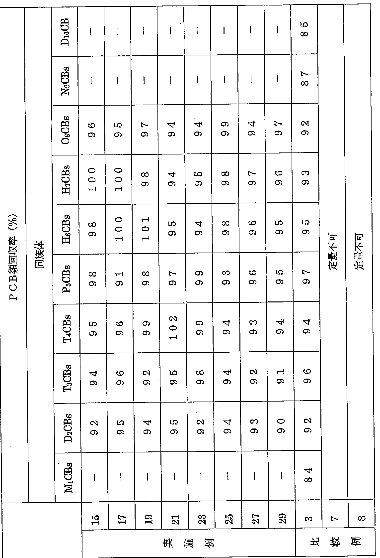


Claims
Priority Applications (5)
| Application Number | Priority Date | Filing Date | Title |
|---|---|---|---|
| CN200880010976XA CN101652651B (zh) | 2007-03-29 | 2008-03-21 | 多氯联苯类的抽提方法 |
| EP08739128.0A EP2136196B1 (en) | 2007-03-29 | 2008-03-21 | Method of extracting polychlorinated biphenyls |
| JP2008551380A JP4465430B2 (ja) | 2007-03-29 | 2008-03-21 | ポリ塩化ビフェニル類の抽出方法 |
| US12/593,483 US8329473B2 (en) | 2007-03-29 | 2008-03-21 | Method for extracting polychlorinated biphenyls |
| KR1020097019144A KR101163431B1 (ko) | 2007-03-29 | 2008-03-21 | 폴리염화비페닐류의 추출 방법 |
Applications Claiming Priority (4)
| Application Number | Priority Date | Filing Date | Title |
|---|---|---|---|
| JP2007-089876 | 2007-03-29 | ||
| JP2007089876 | 2007-03-29 | ||
| JP2007240424 | 2007-09-18 | ||
| JP2007-240424 | 2007-09-18 |
Publications (1)
| Publication Number | Publication Date |
|---|---|
| WO2008123393A1 true WO2008123393A1 (ja) | 2008-10-16 |
Family
ID=39830878
Family Applications (1)
| Application Number | Title | Priority Date | Filing Date |
|---|---|---|---|
| PCT/JP2008/056004 Ceased WO2008123393A1 (ja) | 2007-03-29 | 2008-03-21 | ポリ塩化ビフェニル類の抽出方法 |
Country Status (7)
| Country | Link |
|---|---|
| US (1) | US8329473B2 (ja) |
| EP (1) | EP2136196B1 (ja) |
| JP (1) | JP4465430B2 (ja) |
| KR (1) | KR101163431B1 (ja) |
| CN (1) | CN101652651B (ja) |
| TW (1) | TWI399235B (ja) |
| WO (1) | WO2008123393A1 (ja) |
Cited By (8)
| Publication number | Priority date | Publication date | Assignee | Title |
|---|---|---|---|---|
| WO2010073818A1 (ja) | 2008-12-25 | 2010-07-01 | 国立大学法人愛媛大学 | ポリ塩化ビフェニル類含有油性液体の精製剤 |
| JP2011133453A (ja) * | 2009-11-30 | 2011-07-07 | Hideki Toida | 被分析液抽出装置 |
| JP2013148539A (ja) * | 2012-01-23 | 2013-08-01 | Miura Co Ltd | ポリ塩化ビフェニル類の抽出方法 |
| CN103884812A (zh) * | 2014-03-26 | 2014-06-25 | 昆山洛丹伦生物科技有限公司 | 一种电子元器件塑料部件中多氯化萘的检测方法 |
| JP2015021869A (ja) * | 2013-07-19 | 2015-02-02 | 三浦工業株式会社 | ポリ塩化ビフェニル類の抽出方法 |
| JP2019138774A (ja) * | 2018-02-09 | 2019-08-22 | 三浦工業株式会社 | ポリ塩化ビフェニル類の抽出方法 |
| WO2021033404A1 (ja) | 2019-08-22 | 2021-02-25 | 三浦工業株式会社 | 油類の精製方法 |
| WO2022064749A1 (ja) * | 2020-09-28 | 2022-03-31 | 三浦工業株式会社 | 有機ハロゲン化合物の抽出方法 |
Families Citing this family (11)
| Publication number | Priority date | Publication date | Assignee | Title |
|---|---|---|---|---|
| KR101021690B1 (ko) * | 2010-05-12 | 2011-03-22 | (주)원창에너지 | 폴리염화비페닐을 함유하는 폐절연유의 처리 방법 |
| CN102359994B (zh) * | 2011-07-21 | 2014-01-08 | 广东出入境检验检疫局检验检疫技术中心 | 电子电气产品橡胶部件中多氯萘含量的检测方法 |
| CN103364238B (zh) * | 2012-04-10 | 2015-09-09 | 中国科学院大连化学物理研究所 | 复杂样品中PCNs、HBCDs和TBBPA的选择性分离 |
| CN104084180B (zh) * | 2014-06-30 | 2015-06-17 | 中华人民共和国湖北出入境检验检疫局 | 检测多溴联苯类化合物的多层硅胶净化色谱柱的制备方法 |
| CN106501431B (zh) * | 2016-10-19 | 2017-11-10 | 中国检验认证集团湖北有限公司 | 一种采用硅胶色谱柱检测乳制品中多氯联苯的方法 |
| CN107064395B (zh) * | 2017-06-09 | 2018-12-25 | 中国环境科学研究院 | 复合硅胶柱和用于分析样品中有机污染物的前处理方法 |
| CN111939597A (zh) * | 2020-08-07 | 2020-11-17 | 青岛理工大学 | 一种串联式层析柱装置及方法 |
| CN114264758B (zh) * | 2020-09-16 | 2023-04-07 | 南京理工大学 | 检测沉积物中PCBs、PBDEs和EHFRs的前处理方法 |
| CN113311083B (zh) * | 2021-05-24 | 2022-12-16 | 广东产品质量监督检验研究院(国家质量技术监督局广州电气安全检验所、广东省试验认证研究院、华安实验室) | 一种鱼鳞中七种指示性多氯联苯的测定方法 |
| CN113800657B (zh) * | 2021-10-12 | 2022-11-04 | 中国石油化工股份有限公司 | 一种地下水DNAPLs原位处理方法及处理装置 |
| CN113990407B (zh) * | 2021-10-27 | 2022-08-05 | 北京中科三清环境技术有限公司 | 对多氯萘及其同系物的含量及来源进行解析的解析方法 |
Citations (6)
| Publication number | Priority date | Publication date | Assignee | Title |
|---|---|---|---|---|
| JP2000088825A (ja) * | 1998-09-17 | 2000-03-31 | Ebara Corp | 絶縁油中のポリ塩化ビフェニル類(pcb)分析法 |
| JP2002365273A (ja) * | 2001-06-11 | 2002-12-18 | Nippon Soda Co Ltd | 難分解性ハロゲン化合物の含有量の測定方法。 |
| JP2003114222A (ja) | 2001-07-30 | 2003-04-18 | Central Res Inst Of Electric Power Ind | Pcb分離方法 |
| JP2005140522A (ja) * | 2003-11-04 | 2005-06-02 | Sumika Chemical Analysis Service Ltd | ポリ塩化ビフェニル類を含む油性試料の前処理方法 |
| JP2006047044A (ja) * | 2004-08-03 | 2006-02-16 | Shimadzu Corp | 絶縁油中pcbの分析法 |
| WO2006132027A1 (ja) * | 2005-06-07 | 2006-12-14 | Miura Co., Ltd. | ダイオキシン類の分析用試料調製方法 |
Family Cites Families (8)
| Publication number | Priority date | Publication date | Assignee | Title |
|---|---|---|---|---|
| JPS6168119A (ja) * | 1984-09-11 | 1986-04-08 | Shinryo Air Conditioning Co Ltd | 吸湿剤およびそれを用いた除湿方法 |
| JP2000028598A (ja) * | 1998-07-14 | 2000-01-28 | Ebara Corp | 全自動試料連続精製・分析装置及び精製・分析方法 |
| JP2001330598A (ja) | 2000-05-22 | 2001-11-30 | Fuji Chemical Industries Ltd | 多層充填剤充填カラム |
| US7588725B2 (en) * | 2001-04-25 | 2009-09-15 | Biotrove, Inc. | High throughput autosampler |
| JP4744044B2 (ja) * | 2001-09-27 | 2011-08-10 | 関東化学株式会社 | 脱水剤を分散した繊維マトリックス、その製造方法およびそれを用いたクリーンアップ用カラム |
| EA012032B1 (ru) | 2003-05-15 | 2009-06-30 | Раджу, Канумуру Рахул | Новые функциональные силикаты переходных металлов (ftms) |
| US7344686B2 (en) * | 2004-10-07 | 2008-03-18 | Mesoscopic Devices, Inc. | Desulfurization apparatus with individually controllable heaters |
| JP4003083B2 (ja) * | 2005-08-03 | 2007-11-07 | 株式会社エコアップ | 絶縁油の精製方法 |
-
2008
- 2008-03-21 US US12/593,483 patent/US8329473B2/en not_active Expired - Fee Related
- 2008-03-21 CN CN200880010976XA patent/CN101652651B/zh active Active
- 2008-03-21 KR KR1020097019144A patent/KR101163431B1/ko not_active Expired - Fee Related
- 2008-03-21 JP JP2008551380A patent/JP4465430B2/ja active Active
- 2008-03-21 EP EP08739128.0A patent/EP2136196B1/en active Active
- 2008-03-21 WO PCT/JP2008/056004 patent/WO2008123393A1/ja not_active Ceased
- 2008-03-25 TW TW097110484A patent/TWI399235B/zh active
Patent Citations (6)
| Publication number | Priority date | Publication date | Assignee | Title |
|---|---|---|---|---|
| JP2000088825A (ja) * | 1998-09-17 | 2000-03-31 | Ebara Corp | 絶縁油中のポリ塩化ビフェニル類(pcb)分析法 |
| JP2002365273A (ja) * | 2001-06-11 | 2002-12-18 | Nippon Soda Co Ltd | 難分解性ハロゲン化合物の含有量の測定方法。 |
| JP2003114222A (ja) | 2001-07-30 | 2003-04-18 | Central Res Inst Of Electric Power Ind | Pcb分離方法 |
| JP2005140522A (ja) * | 2003-11-04 | 2005-06-02 | Sumika Chemical Analysis Service Ltd | ポリ塩化ビフェニル類を含む油性試料の前処理方法 |
| JP2006047044A (ja) * | 2004-08-03 | 2006-02-16 | Shimadzu Corp | 絶縁油中pcbの分析法 |
| WO2006132027A1 (ja) * | 2005-06-07 | 2006-12-14 | Miura Co., Ltd. | ダイオキシン類の分析用試料調製方法 |
Non-Patent Citations (3)
| Title |
|---|
| FUJITA H. ET AL.: "Dioxin-rui Bunseki ni Okeru Kanetsu Taso Silica Gel Column Seiseiho no Kento", JOURNAL OF ENVIRONMENTAL CHEMISTRY, vol. 15, no. 1, 25 March 2005 (2005-03-25), pages 117 - 128, XP008120826 * |
| FUJITA H. ET AL.: "GC-MS-ho Oyobi Seibutsu Kenteiho ni yoru Dioxin-rui Sokutei no Tamento Kan'i Seisei. Noshukuho ni Kansuru Kento", JOURNAL OF ENVIRONMENTAL CHEMISTRY, vol. 15, no. 3, 22 September 2005 (2005-09-22), pages 585 - 596, XP008120814 * |
| NONDEK L. ET AL.: "LC Clean-up and GC/MS Analysis of Polycyclic Aromatic Hydrocarbons in River Sediment", CHROMATOGRAPHIA, vol. 37, no. 7/8, October 1993 (1993-10-01), pages 381 - 386, XP008120654 * |
Cited By (18)
| Publication number | Priority date | Publication date | Assignee | Title |
|---|---|---|---|---|
| CN102077073B (zh) * | 2008-12-25 | 2013-08-14 | 国立大学法人爱媛大学 | 含多氯联苯类的油性液体的净化剂 |
| US9157899B2 (en) | 2008-12-25 | 2015-10-13 | Ehime University | Purifying agent for oily liquid containing polychlorinated biphenyls |
| CN102077073A (zh) * | 2008-12-25 | 2011-05-25 | 国立大学法人爱媛大学 | 含多氯联苯类的油性液体的净化剂 |
| WO2010073818A1 (ja) | 2008-12-25 | 2010-07-01 | 国立大学法人愛媛大学 | ポリ塩化ビフェニル類含有油性液体の精製剤 |
| JPWO2010073818A1 (ja) * | 2008-12-25 | 2012-06-14 | 国立大学法人愛媛大学 | ポリ塩化ビフェニル類含有油性液体の精製剤 |
| EP2345883A4 (en) * | 2008-12-25 | 2012-09-05 | Univ Ehime | CLEANSING AGENT FOR OILY LIQUIDS WITH POLYBIPHENYL CHLORIDE |
| KR101250025B1 (ko) * | 2008-12-25 | 2013-04-03 | 미우라고교 가부시키카이샤 | 폴리염화비페닐류 함유 유성 액체의 정제제 |
| TWI425983B (zh) * | 2008-12-25 | 2014-02-11 | Univ Ehime | 用以精製含有多氯聯苯類物質之油性液體之製劑 |
| JP4538615B2 (ja) * | 2008-12-25 | 2010-09-08 | 国立大学法人愛媛大学 | ポリ塩化ビフェニル類含有油性液体の精製剤 |
| JP2014145779A (ja) * | 2009-11-30 | 2014-08-14 | Hideki Toida | 被分析液抽出装置 |
| JP2011133453A (ja) * | 2009-11-30 | 2011-07-07 | Hideki Toida | 被分析液抽出装置 |
| JP2013148539A (ja) * | 2012-01-23 | 2013-08-01 | Miura Co Ltd | ポリ塩化ビフェニル類の抽出方法 |
| JP2015021869A (ja) * | 2013-07-19 | 2015-02-02 | 三浦工業株式会社 | ポリ塩化ビフェニル類の抽出方法 |
| CN103884812A (zh) * | 2014-03-26 | 2014-06-25 | 昆山洛丹伦生物科技有限公司 | 一种电子元器件塑料部件中多氯化萘的检测方法 |
| JP2019138774A (ja) * | 2018-02-09 | 2019-08-22 | 三浦工業株式会社 | ポリ塩化ビフェニル類の抽出方法 |
| JP7015705B2 (ja) | 2018-02-09 | 2022-02-03 | 三浦工業株式会社 | ポリ塩化ビフェニル類の抽出方法 |
| WO2021033404A1 (ja) | 2019-08-22 | 2021-02-25 | 三浦工業株式会社 | 油類の精製方法 |
| WO2022064749A1 (ja) * | 2020-09-28 | 2022-03-31 | 三浦工業株式会社 | 有機ハロゲン化合物の抽出方法 |
Also Published As
| Publication number | Publication date |
|---|---|
| EP2136196A4 (en) | 2012-09-05 |
| KR101163431B1 (ko) | 2012-07-13 |
| EP2136196B1 (en) | 2018-06-27 |
| CN101652651A (zh) | 2010-02-17 |
| TW200902485A (en) | 2009-01-16 |
| US20100116023A1 (en) | 2010-05-13 |
| EP2136196A1 (en) | 2009-12-23 |
| JPWO2008123393A1 (ja) | 2010-07-15 |
| US8329473B2 (en) | 2012-12-11 |
| TWI399235B (zh) | 2013-06-21 |
| CN101652651B (zh) | 2012-03-21 |
| KR20100014393A (ko) | 2010-02-10 |
| JP4465430B2 (ja) | 2010-05-19 |
Similar Documents
| Publication | Publication Date | Title |
|---|---|---|
| WO2008123393A1 (ja) | ポリ塩化ビフェニル類の抽出方法 | |
| JP4538615B2 (ja) | ポリ塩化ビフェニル類含有油性液体の精製剤 | |
| EP3913362A1 (en) | Method for fractionating dioxin-type compounds | |
| JP5696861B2 (ja) | ポリ塩化ビフェニル類の抽出方法 | |
| JP5626538B2 (ja) | ポリ塩化ビフェニル類の抽出方法 | |
| JP6086597B2 (ja) | ポリ塩化ビフェニル類の抽出方法 | |
| JP5891816B2 (ja) | ダイオキシン類の抽出方法 | |
| JP5691120B2 (ja) | 高濃度硫酸含有シリカゲルの製造法 | |
| JP4956768B2 (ja) | ポリ塩化ビフェニル類の抽出方法 | |
| JP4764215B2 (ja) | ポリ塩化ビフェニル類の定量方法およびこれに用いるアンプル | |
| WO2023119935A1 (ja) | モノオルソポリ塩化ビフェニル類含有脂肪族炭化水素溶媒溶液の処理器具 | |
| JP4609696B2 (ja) | 電線ケーブル中の有機塩素化合物の抽出方法およびこれを用いる有機塩素化合物の分析方法 | |
| JP4632813B2 (ja) | ポリ塩化ビフェニル類の定量方法 | |
| JP2009168459A (ja) | 抽出装置 | |
| WO2022176252A1 (ja) | 有機ハロゲン化合物の抽出方法 | |
| Toader et al. | SPME EXTRACTION OF THE PCB'S CONTAINING TRANSFORMER OILS | |
| Ferri et al. | Remediation of Contaminated Soils By Supercritical Carbon Dioxide Extraction |
Legal Events
| Date | Code | Title | Description |
|---|---|---|---|
| WWE | Wipo information: entry into national phase |
Ref document number: 200880010976.X Country of ref document: CN |
|
| WWE | Wipo information: entry into national phase |
Ref document number: 2008551380 Country of ref document: JP |
|
| 121 | Ep: the epo has been informed by wipo that ep was designated in this application |
Ref document number: 08739128 Country of ref document: EP Kind code of ref document: A1 |
|
| WWE | Wipo information: entry into national phase |
Ref document number: 1020097019144 Country of ref document: KR |
|
| WWE | Wipo information: entry into national phase |
Ref document number: 12593483 Country of ref document: US |
|
| NENP | Non-entry into the national phase |
Ref country code: DE |
|
| WWE | Wipo information: entry into national phase |
Ref document number: 2008739128 Country of ref document: EP |