WO2009018522A1 - High hardness, high toughness iron-base alloys and methods for making same - Google Patents
High hardness, high toughness iron-base alloys and methods for making same Download PDFInfo
- Publication number
- WO2009018522A1 WO2009018522A1 PCT/US2008/071931 US2008071931W WO2009018522A1 WO 2009018522 A1 WO2009018522 A1 WO 2009018522A1 US 2008071931 W US2008071931 W US 2008071931W WO 2009018522 A1 WO2009018522 A1 WO 2009018522A1
- Authority
- WO
- WIPO (PCT)
- Prior art keywords
- alloy
- hbn
- hardness
- armor
- samples
- Prior art date
- Legal status (The legal status is an assumption and is not a legal conclusion. Google has not performed a legal analysis and makes no representation as to the accuracy of the status listed.)
- Ceased
Links
Classifications
-
- C—CHEMISTRY; METALLURGY
- C22—METALLURGY; FERROUS OR NON-FERROUS ALLOYS; TREATMENT OF ALLOYS OR NON-FERROUS METALS
- C22C—ALLOYS
- C22C38/00—Ferrous alloys, e.g. steel alloys
- C22C38/18—Ferrous alloys, e.g. steel alloys containing chromium
- C22C38/40—Ferrous alloys, e.g. steel alloys containing chromium with nickel
- C22C38/44—Ferrous alloys, e.g. steel alloys containing chromium with nickel with molybdenum or tungsten
-
- C—CHEMISTRY; METALLURGY
- C21—METALLURGY OF IRON
- C21D—MODIFYING THE PHYSICAL STRUCTURE OF FERROUS METALS; GENERAL DEVICES FOR HEAT TREATMENT OF FERROUS OR NON-FERROUS METALS OR ALLOYS; MAKING METAL MALLEABLE, e.g. BY DECARBURISATION OR TEMPERING
- C21D1/00—General methods or devices for heat treatment, e.g. annealing, hardening, quenching or tempering
- C21D1/56—General methods or devices for heat treatment, e.g. annealing, hardening, quenching or tempering characterised by the quenching agents
-
- C—CHEMISTRY; METALLURGY
- C21—METALLURGY OF IRON
- C21D—MODIFYING THE PHYSICAL STRUCTURE OF FERROUS METALS; GENERAL DEVICES FOR HEAT TREATMENT OF FERROUS OR NON-FERROUS METALS OR ALLOYS; MAKING METAL MALLEABLE, e.g. BY DECARBURISATION OR TEMPERING
- C21D6/00—Heat treatment of ferrous alloys
- C21D6/004—Heat treatment of ferrous alloys containing Cr and Ni
-
- C—CHEMISTRY; METALLURGY
- C21—METALLURGY OF IRON
- C21D—MODIFYING THE PHYSICAL STRUCTURE OF FERROUS METALS; GENERAL DEVICES FOR HEAT TREATMENT OF FERROUS OR NON-FERROUS METALS OR ALLOYS; MAKING METAL MALLEABLE, e.g. BY DECARBURISATION OR TEMPERING
- C21D6/00—Heat treatment of ferrous alloys
- C21D6/005—Heat treatment of ferrous alloys containing Mn
-
- C—CHEMISTRY; METALLURGY
- C21—METALLURGY OF IRON
- C21D—MODIFYING THE PHYSICAL STRUCTURE OF FERROUS METALS; GENERAL DEVICES FOR HEAT TREATMENT OF FERROUS OR NON-FERROUS METALS OR ALLOYS; MAKING METAL MALLEABLE, e.g. BY DECARBURISATION OR TEMPERING
- C21D6/00—Heat treatment of ferrous alloys
- C21D6/008—Heat treatment of ferrous alloys containing Si
-
- C—CHEMISTRY; METALLURGY
- C21—METALLURGY OF IRON
- C21D—MODIFYING THE PHYSICAL STRUCTURE OF FERROUS METALS; GENERAL DEVICES FOR HEAT TREATMENT OF FERROUS OR NON-FERROUS METALS OR ALLOYS; MAKING METAL MALLEABLE, e.g. BY DECARBURISATION OR TEMPERING
- C21D7/00—Modifying the physical properties of iron or steel by deformation
- C21D7/13—Modifying the physical properties of iron or steel by deformation by hot working
-
- C—CHEMISTRY; METALLURGY
- C21—METALLURGY OF IRON
- C21D—MODIFYING THE PHYSICAL STRUCTURE OF FERROUS METALS; GENERAL DEVICES FOR HEAT TREATMENT OF FERROUS OR NON-FERROUS METALS OR ALLOYS; MAKING METAL MALLEABLE, e.g. BY DECARBURISATION OR TEMPERING
- C21D8/00—Modifying the physical properties of ferrous metals or ferrous alloys by deformation combined with, or followed by, heat treatment
- C21D8/02—Modifying the physical properties of ferrous metals or ferrous alloys by deformation combined with, or followed by, heat treatment during manufacturing of plates or strips
- C21D8/0221—Modifying the physical properties of ferrous metals or ferrous alloys by deformation combined with, or followed by, heat treatment during manufacturing of plates or strips characterised by the working steps
- C21D8/0226—Hot rolling
-
- C—CHEMISTRY; METALLURGY
- C21—METALLURGY OF IRON
- C21D—MODIFYING THE PHYSICAL STRUCTURE OF FERROUS METALS; GENERAL DEVICES FOR HEAT TREATMENT OF FERROUS OR NON-FERROUS METALS OR ALLOYS; MAKING METAL MALLEABLE, e.g. BY DECARBURISATION OR TEMPERING
- C21D8/00—Modifying the physical properties of ferrous metals or ferrous alloys by deformation combined with, or followed by, heat treatment
- C21D8/02—Modifying the physical properties of ferrous metals or ferrous alloys by deformation combined with, or followed by, heat treatment during manufacturing of plates or strips
- C21D8/0247—Modifying the physical properties of ferrous metals or ferrous alloys by deformation combined with, or followed by, heat treatment during manufacturing of plates or strips characterised by the heat treatment
- C21D8/0263—Modifying the physical properties of ferrous metals or ferrous alloys by deformation combined with, or followed by, heat treatment during manufacturing of plates or strips characterised by the heat treatment following hot rolling
-
- C—CHEMISTRY; METALLURGY
- C21—METALLURGY OF IRON
- C21D—MODIFYING THE PHYSICAL STRUCTURE OF FERROUS METALS; GENERAL DEVICES FOR HEAT TREATMENT OF FERROUS OR NON-FERROUS METALS OR ALLOYS; MAKING METAL MALLEABLE, e.g. BY DECARBURISATION OR TEMPERING
- C21D9/00—Heat treatment, e.g. annealing, hardening, quenching or tempering, adapted for particular articles; Furnaces therefor
- C21D9/0075—Heat treatment, e.g. annealing, hardening, quenching or tempering, adapted for particular articles; Furnaces therefor for rods of limited length
-
- C—CHEMISTRY; METALLURGY
- C21—METALLURGY OF IRON
- C21D—MODIFYING THE PHYSICAL STRUCTURE OF FERROUS METALS; GENERAL DEVICES FOR HEAT TREATMENT OF FERROUS OR NON-FERROUS METALS OR ALLOYS; MAKING METAL MALLEABLE, e.g. BY DECARBURISATION OR TEMPERING
- C21D9/00—Heat treatment, e.g. annealing, hardening, quenching or tempering, adapted for particular articles; Furnaces therefor
- C21D9/42—Heat treatment, e.g. annealing, hardening, quenching or tempering, adapted for particular articles; Furnaces therefor for armour plate
-
- C—CHEMISTRY; METALLURGY
- C21—METALLURGY OF IRON
- C21D—MODIFYING THE PHYSICAL STRUCTURE OF FERROUS METALS; GENERAL DEVICES FOR HEAT TREATMENT OF FERROUS OR NON-FERROUS METALS OR ALLOYS; MAKING METAL MALLEABLE, e.g. BY DECARBURISATION OR TEMPERING
- C21D9/00—Heat treatment, e.g. annealing, hardening, quenching or tempering, adapted for particular articles; Furnaces therefor
- C21D9/46—Heat treatment, e.g. annealing, hardening, quenching or tempering, adapted for particular articles; Furnaces therefor for sheet metals
-
- C—CHEMISTRY; METALLURGY
- C22—METALLURGY; FERROUS OR NON-FERROUS ALLOYS; TREATMENT OF ALLOYS OR NON-FERROUS METALS
- C22C—ALLOYS
- C22C38/00—Ferrous alloys, e.g. steel alloys
- C22C38/001—Ferrous alloys, e.g. steel alloys containing N
-
- C—CHEMISTRY; METALLURGY
- C22—METALLURGY; FERROUS OR NON-FERROUS ALLOYS; TREATMENT OF ALLOYS OR NON-FERROUS METALS
- C22C—ALLOYS
- C22C38/00—Ferrous alloys, e.g. steel alloys
- C22C38/005—Ferrous alloys, e.g. steel alloys containing rare earths, i.e. Sc, Y, Lanthanides
-
- C—CHEMISTRY; METALLURGY
- C22—METALLURGY; FERROUS OR NON-FERROUS ALLOYS; TREATMENT OF ALLOYS OR NON-FERROUS METALS
- C22C—ALLOYS
- C22C38/00—Ferrous alloys, e.g. steel alloys
- C22C38/02—Ferrous alloys, e.g. steel alloys containing silicon
-
- C—CHEMISTRY; METALLURGY
- C22—METALLURGY; FERROUS OR NON-FERROUS ALLOYS; TREATMENT OF ALLOYS OR NON-FERROUS METALS
- C22C—ALLOYS
- C22C38/00—Ferrous alloys, e.g. steel alloys
- C22C38/04—Ferrous alloys, e.g. steel alloys containing manganese
-
- C—CHEMISTRY; METALLURGY
- C22—METALLURGY; FERROUS OR NON-FERROUS ALLOYS; TREATMENT OF ALLOYS OR NON-FERROUS METALS
- C22C—ALLOYS
- C22C38/00—Ferrous alloys, e.g. steel alloys
- C22C38/06—Ferrous alloys, e.g. steel alloys containing aluminium
-
- C—CHEMISTRY; METALLURGY
- C22—METALLURGY; FERROUS OR NON-FERROUS ALLOYS; TREATMENT OF ALLOYS OR NON-FERROUS METALS
- C22C—ALLOYS
- C22C38/00—Ferrous alloys, e.g. steel alloys
- C22C38/18—Ferrous alloys, e.g. steel alloys containing chromium
- C22C38/40—Ferrous alloys, e.g. steel alloys containing chromium with nickel
- C22C38/46—Ferrous alloys, e.g. steel alloys containing chromium with nickel with vanadium
-
- C—CHEMISTRY; METALLURGY
- C22—METALLURGY; FERROUS OR NON-FERROUS ALLOYS; TREATMENT OF ALLOYS OR NON-FERROUS METALS
- C22C—ALLOYS
- C22C38/00—Ferrous alloys, e.g. steel alloys
- C22C38/18—Ferrous alloys, e.g. steel alloys containing chromium
- C22C38/40—Ferrous alloys, e.g. steel alloys containing chromium with nickel
- C22C38/50—Ferrous alloys, e.g. steel alloys containing chromium with nickel with titanium or zirconium
-
- C—CHEMISTRY; METALLURGY
- C22—METALLURGY; FERROUS OR NON-FERROUS ALLOYS; TREATMENT OF ALLOYS OR NON-FERROUS METALS
- C22C—ALLOYS
- C22C38/00—Ferrous alloys, e.g. steel alloys
- C22C38/18—Ferrous alloys, e.g. steel alloys containing chromium
- C22C38/40—Ferrous alloys, e.g. steel alloys containing chromium with nickel
- C22C38/52—Ferrous alloys, e.g. steel alloys containing chromium with nickel with cobalt
-
- C—CHEMISTRY; METALLURGY
- C22—METALLURGY; FERROUS OR NON-FERROUS ALLOYS; TREATMENT OF ALLOYS OR NON-FERROUS METALS
- C22C—ALLOYS
- C22C38/00—Ferrous alloys, e.g. steel alloys
- C22C38/18—Ferrous alloys, e.g. steel alloys containing chromium
- C22C38/40—Ferrous alloys, e.g. steel alloys containing chromium with nickel
- C22C38/54—Ferrous alloys, e.g. steel alloys containing chromium with nickel with boron
-
- C—CHEMISTRY; METALLURGY
- C22—METALLURGY; FERROUS OR NON-FERROUS ALLOYS; TREATMENT OF ALLOYS OR NON-FERROUS METALS
- C22C—ALLOYS
- C22C38/00—Ferrous alloys, e.g. steel alloys
- C22C38/60—Ferrous alloys, e.g. steel alloys containing lead, selenium, tellurium, or antimony, or more than 0.04% by weight of sulfur
Definitions
- the present disclosure relates to iron-base alloys having hardness greater than 550 HBN and demonstrating substantial and unexpected penetration resistance in standard ballistic testing, and to armor and other articles of manufacture including the alloys.
- the present disclosure further relates to methods of processing certain iron-base alloys so as to improve resistance to ballistic penetration.
- Armor plate, sheet, and bar are commonly provided to protect structures against forcibly launched projectiles.
- armor plate, sheet, and bar are typically used in military applications as a means to protect personnel and property within, for example, vehicles and mechanized armaments, the products also have various civilian uses. Such uses include, for example, sheathing for armored civilian vehicles and blast-fortified property enclosures.
- Armor has been produced from a variety of materials including, for example, polymers, ceramics, and metallic alloys. Because armor is often mounted on mobile articles, armor weight is typically an important factor. Also, the costs associated with producing armor can be substantial, and particularly so in connection with exotic armor alloys, ceramics, and specialty polymers. As such, an objective has been to provide lower-cost yet effective alternatives to existing armors, and without significantly increasing the weight of armor necessary to achieve the desired level of ballistic performance (penetration resistance).
- titanium alloy armors examples include Ti-6AI-4V, Ti-6AI-4V ELI, and Ti-4AI-2.5V-Fe-O.
- Titanium alloys offer many advantages relative to more conventional rolled homogenous steel armor. Titanium alloys have a high mass efficiency compared with rolled homogenous steel and aluminum alloys across a broad spectrum of ballistic threats, and also provide favorable multi-hit ballistic penetration resistance capability. Titanium alloys also exhibit generally higher strength-to-weight ratios, as well as substantial corrosion resistance, typically resulting in lower asset maintenance costs. Titanium alloys may be readily fabricated in existing production facilities, and titanium scrap and mill revert can be remelted and recycled on a commercial scale. Nevertheless, titanium alloys do have disadvantages.
- a spall liner typically is required, and the costs associated with manufacturing the titanium armor plate and fabricating products from the material (for example, machining and welding costs) are substantially higher than for rolled homogenous steel armors.
- PMCs offer some advantages (for example, freedom from spalling against chemical threats, quieter operator environment, and high mass efficiency against ball and fragment ballistic threats), they also suffer from a number of disadvantages.
- the cost of fabricating PMC components is high compared with the cost for fabricating components from rolled homogenous steel or titanium alloys, and PMCs cannot readily be fabricated in existing production facilities.
- non-destructive testing of PMC materials may not be as well advanced as for testing of alloy armors.
- multi-hit ballistic penetration resistance capability and automotive load-bearing capacity of PMCs can be adversely affected by structural changes that occur as the result of an initial projectile strike.
- Metallic alloys are often the material of choice when selecting an armor material.
- Metallic alloys offer substantial multi-hit protection, typically are inexpensive to produce relative to exotic ceramics, polymers, and composites, and may be readily fabricated into components for armored combat vehicles and mobile armament systems. It is conventionally believed that it is advantageous to use materials having very high hardnesses in armor applications because projectiles are more likely to fragment when impacting higher hardness materials.
- Certain metallic alloys used in armor application may be readily processed to high hardnesses, typically by quenching the alloys from very high temperatures.
- composite armors for example, combine a front-facing layer of high-hardness steel metallurgically bonded to a tough, penetration resistant steel base layer.
- the high-hardness steel layer is intended to break up the projectile, while the tough underlayer is intended to prevent the armor from cracking, shattering, or spalling.
- Conventional methods of forming a composite armor of this type include roll bonding stacked plates of the two steel types.
- K12 ® armor plate which is a dual hardness, roll bonded composite armor plate available from ATI Allegheny Ludlum, Pittsburgh, Pennsylvania.
- K12 ® armor plate includes a high hardness front side and a softer back side.
- K12 ® armor plate Both faces of the K12 ® armor plate are Ni-Mo-Cr alloy steel, but the front side includes higher carbon content than the back side.
- K12 ® armor plate has superior ballistic performance properties compared to conventional homogenous armor plate and meets or exceeds the ballistic requirements for numerous government, military, and civilian armoring applications.
- clad and composite steel armors offer numerous advantages, the additional processing involved in the cladding or roll bonding process necessarily increases the cost of the armor systems.
- Relatively inexpensive low alloy content steels also are used in certain armor applications.
- certain low alloy steel armors can be produced with very high hardness properties, greater than 550 BHN (Brinell hardness number).
- Such high hardness steels are commonly known as "600 BHN" steels.
- Table 1 provides reported compositions and mechanical properties for several examples of available 600 BHN steels used in armor applications.
- MARS 300 and MARS 300 Ni+ are produced by the French company Arcelor.
- ARMOX 600T armor is available from SSAB Oxelosund AB, Sweden.
- an iron- base alloy having favorable multi-hit ballistic resistance, hardness greater than 550 HBN, and including, in weight percentages based on total alloy weight: 0.48 to 0.52 carbon; 0.15 to 1.00 manganese; 0.15 to 0.45 silicon; 0.95 to 1.70 chromium; 3.30 to 4.30 nickel; 0.35 to 0.65 molybdenum; 0.0008 to 0.0030 boron; 0.001 to 0.015 cerium; 0.001 to 0.015 lanthanum; no greater than 0.002 sulfur; no greater than 0.015 phosphorus; no greater than 0.010 nitrogen; iron; and incidental impurities.
- an alloy mill product such as, for example, a plate, a bar, or a sheet, having hardness greater than 550 HBN and including, in weight percentages based on total alloy weight: 0.48 to 0.52 carbon; 0.15 to 1.00 manganese; 0.15 to 0.45 silicon; 0.95 to 1.70 chromium; 3.30 to 4.30 nickel; 0.35 to 0.65 molybdenum; 0.0008 to 0.0030 boron; 0.001 to 0.015 cerium; 0.001 to 0.015 lanthanum; no greater than 0.002 sulfur; no greater than 0.015 phosphorus; no greater than 0.010 nitrogen; iron; and incidental impurities.
- an armor mill product selected from an armor plate, an armor bar, and an armor sheet having hardness greater than 550 HBN and a V 50 ballistic limit (protection) that meets or exceeds performance requirements under specification MIL-DTL- 46100E.
- the armor mill product also has a V 50 ballistic limit that is at least as great as a V 50 ballistic limit 150 ft/sec less than the performance requirements under specification MIL-A-46099C with minimal crack propagation.
- the mill product is an alloy including, in weight percentages based on total alloy weight: 0.48 to 0.52 carbon; 0.15 to 1.00 manganese; 0.15 to 0.45 silicon; 0.95 to 1.70 chromium; 3.30 to 4.30 nickel; 0.35 to 0.65 molybdenum; 0.0008 to 0.0030 boron; 0.001 to 0.015 cerium; 0.001 to 0.015 lanthanum; no greater than 0.002 sulfur; no greater than 0.015 phosphorus; no greater than 0.010 nitrogen; iron; and incidental impurities.
- An additional aspect according to the present disclosure is directed to a method of making an alloy having favorable multi-hit ballistic resistance with minimal crack propagation and hardness greater than 550 HBN, and wherein the mill product is an alloy including, in weight percentages based on total alloy weight: 0.48 to 0.52 carbon; 0.15 to 1.00 manganese; 0.15 to 0.45 silicon; 0.95 to 1.70 chromium; 3.30 to 4.30 nickel; 0.35 to 0.65 molybdenum; 0.0008 to 0.0030 boron; 0.001 to 0.015 cerium; 0.001 to 0.015 lanthanum; no greater than 0.002 sulfur; no greater than 0.015 phosphorus; no greater than 0.010 nitrogen; iron; and incidental impurities.
- the alloy is austenitized by heating the alloy to a temperature of at least 1500oF and holding for at least 30 minutes time-at-temperature.
- the alloy is then cooled from the austenitizing temperature in a manner that differs from the conventional manner of cooling armor alloy from the austenitizing temperature and which alters the path of the cooling curve of the alloy relative to the path the curve would assume if the alloy were cooled in a conventional manner.
- cooling the alloy from the austenitizing temperature provides the alloy with a V 5 o ballistic limit that meets or exceeds the required V 50 under specification MIL-DTL-46100E.
- cooling the alloy from the austenitizing temperature provides the alloy with a V 50 ballistic limit that is no less than 150 ft/sec less than the required V 50 under specification MIL-A-46099C with minimal crack propagation.
- the V 50 ballistic limit preferably is at least as great as a V 5 o 150 ft/sec less than the required V 50 under specification MIL-A-46099C with minimal crack propagation
- the step of cooling the alloy comprises simultaneously cooling multiple plates of the alloy from the austenitizing temperature with the plates arranged in contact with one another.
- articles of manufacture comprising embodiments of alloys according to the present disclosure.
- Such articles of manufacture include, for example, armored vehicles, armored enclosures, and items of armored mobile equipment.
- Figure 1 is a plot of HRc hardness as a function of austenitizing treatment heating temperature for certain experimental plate samples processed as described hereinbelow;
- Figure 2 is a plot of HRc hardness as a function of austenitizing treatment heating temperature for certain non-limiting experimental plate samples processed as described hereinbelow;
- Figure 3 is a plot of HRc hardness as a function of austenitizing treatment heating temperature for certain non-limiting experimental plate samples processed as described hereinbelow;
- Figures 4, 5 and 7 are schematic representations of arrangements of test samples used during cooling from austenitizing temperature;
- Figure 6 is a plot of V 50 velocity over required minimum V 5 o velocity (as per MIL-A-46099C) as a function of tempering practice for certain test samples;
- Figures 8 and 9 are plots of sample temperature over time during steps of cooling of certain test samples from an austenitizing temperature
- Figures 10 and 11 are schematic representations of arrangements of test samples used during cooling from austenitizing temperature.
- Figures 12-14 are graphs plotting samples temperature over time for several experimental samples cooled from austenitizing temperature, as discussed herein.
- the present disclosure in part, is directed to low-alloy steels having significant hardness and demonstrating a substantial and unexpected level of multi-hit ballistic resistance with minimal crack propagation imparting a level of ballistic penetration resistance suitable for military armor applications.
- Certain embodiments of the steels according to the present disclosure exhibit hardness values in excess of 550 HBN and demonstrate a substantial level of ballistic penetration resistance when evaluated as per MIL-DTL-46100E, and preferably also when evaluated per MIL-A- 46099C.
- certain embodiments of the alloys according to the present disclosure are significantly less susceptible to cracking and penetration when tested against armor piercing projectiles.
- Certain embodiments of the alloys also have demonstrated ballistic performance that is comparable to the performance of certain high-alloy armor materials, such as K-12 ® armor plate.
- the ballistic performance of certain embodiments of steel alloys according to the present disclosure was wholly unexpected given, for example, the low alloy content of the alloys and the alloys' relatively moderate hardness compared with certain conventional 600 BHN steel armor materials. More particularly, it was unexpectedly observed that although certain embodiments of alloys according to the present disclosure exhibit relatively moderate hardnesses (which can be provided by cooling the alloys from austenitizing temperatures at a relatively slow cooling rate), the samples of the alloys exhibited substantial ballistic performance, which was at least comparable to the performance of K-12 ® armor plate.
- Certain embodiments of steels according to the present disclosure include low levels of the residual elements sulfur, phosphorus, nitrogen, and oxygen. Also, certain embodiments of the steels may include concentrations of one or more of cerium, lanthanum, and other rare earth metals. Without being bound to any particular theory of operation, the inventors believe that the rare earth additions act to bind some portion of sulfur, phosphorus, and/or oxygen present in the alloy so that these residuals are less likely to concentrate in grain boundaries and reduce the multi-hit ballistic resistance of the material.
- Certain embodiments of the steels according to the present disclosure also include relatively high nickel content, for example 3.30 to 4.30 weight percent, to provide a relatively tough matrix, thereby significantly improving ballistic performance.
- the inventors In addition to developing a unique alloy system, the inventors also conducted studies, discussed below, to determine how one may process steels within the present disclosure to improve hardness and ballistic performance as evaluated per known military specifications MIL-DTL-46100E and MIL-A-46099C. The inventors also subjected samples of steel according to the present disclosure to various temperatures intended to dissolve carbide particles within the steel and to allow diffusion and produce a reasonable degree of homogeneity within the steel. An objective of this testing was to determine heat treating temperatures that do not produce excessive carburization or result in excessive and unacceptable grain growth, which would reduce material toughness and thereby degrade ballistic performance. In certain processes, the plates of the steel were cross rolled to provide some degree of isotropy.
- a novel composition for low-alloy steel armors was formulated.
- the present inventors concluded that such alloy composition preferably should include relatively high nickel content and low levels of sulfur, phosphorus, and nitrogen residual elements, and should be processed to plate form in a way that promotes homogeneity.
- Table 2 indicates the desired minimum and maximum, preferred minimum and preferred maximum (if any), and aim levels of the alloying ingredients, as well as the actual chemistry of the alloy produced.
- the balance of the alloy included iron and incidental impurities.
- Non-limiting examples of elements that may be present as incidental impurities include copper, aluminum, titanium, tungsten, and cobalt.
- Other potential incidental impurities which may be derived from the starting materials and/or through alloy processing, will be known to persons having ordinary skill in metallurgy. Alloy compositions are reported in Table
- Ingot surfaces were ground using conventional practices. The ingots were then heated to about 1300oF (704oC), equalized, held at this first temperature for 6 to 8 hours, heated at about 200°F/hour (93°C/hour) up to about 2050°F (1121 oC)1 and held at the second temperature for about 30 minutes per inch of thickness. Ingots were then hot rolled to 7 inch (17.8 cm) thickness, end cropped and, if necessary, reheated to about 2050oF (1121 oC) before subsequent additional hot rolling to reslabs of about 1.50-2.50 inches (38.1-63.5 cm) in thickness.
- the reslabs were stress relief annealed using conventional practices, and slab surfaces were then blast cleaned and finish rolled to long plates having thicknesses of either about 0.310 inch (7.8 mm) or about 0.275 inch (7 mm).
- the long plates were then fully annealed, blast cleaned, flattened, and sheared to form multiple individual plates having a thickness of either about 0.310 inch (7.8 mm) or about 0.275 inch (7 mm).
- the reslabs were reheated to rolling temperature immediately before the final rolling step necessary to achieve finished gauge. More specifically, the plate samples were final rolled as shown in Table 3. Tests were conducted on samples of the 0.0275 and 0.310 inch (7 and 7.8 mm) gauge (nominal) plates that were final rolled as shown in Table 3 to assess possible heat treatment parameters optimizing surface hardness and ballistic performance properties.
- Plates produced as in Section 1 above were subjected to an austenitizing treatment and a hardening step, cut into thirds to form samples for further testing and, optionally, subjected to a tempering treatment.
- the austenitizing treatment involved heating the samples to 1550-1650oF (843-899°C) for 40 minutes time-at-temperature.
- Hardening involved air-cooling the samples or quenching the samples in oil from the austenitizing treatment temperature to room temperature ("RT").
- RT room temperature
- the remaining two samples cut from each austenitized and hardened plate were temper annealed by holding at either 250oF (121 oC) or 300oF (149°C) for 90 minutes time-at-temperature.
- HR C Rockwell C
- the two samples exhibiting the highest HRc values in the as-hardened state were also tested to determine Brinell hardness (BHN) in the as-hardened state (i.e., before any tempering treatment).
- Table 4 lists austenitizing treatment temperatures, quench type, gauge, and HRc values for samples tempered at either 250°F (121 oC) or 300oF (149°C). Table 4 also indicates whether the plates used in the testing were subjected to reheating immediately prior to rolling to final gauge.
- Table 4 lists BHN hardness for the untempered, as-hardened samples exhibiting the highest HRc values in the as-hardened condition.
- Table 5 provides average HRc values for the samples included in Table 4 in the as-hardened state and after temper anneals of either 250oF (121 oC) or 300oF (149°C) for 90 minutes time-at-temperature.
- Brinell hardness is determined per specification ASTM E-10 by forcing an indenter in the form of a hard steel or carbide sphere of a specified diameter under a specified load into the surface of the sample and measuring the diameter of the indentation left after the test.
- the Brinell hardness number or "BHN" is obtained by dividing the indenter load used (in kilograms) by the actual surface area of the indentation (in square millimeters). The result is a pressure measurement, but the units are rarely stated when BHN values are reported.
- a desk top machine is used to press a 10 mm diameter tungsten carbide sphere indenter into the surface of the test specimen.
- the machine applies a load of 3000 kilograms, usually for 10 seconds. After the ball is retracted, the diameter of the resulting round impression is determined.
- the BHN value is calculated according to the following formula:
- BHN tests may be carried out on a surface region of an armor plate and each test might result in a slightly different hardness number. This variation in hardness can be due to minor variations in the local chemistry and microstructure of the plate since even homogenous armors are not absolutely uniform. Small variations in hardness measures also can result from errors in measuring the diameter of the indenter impression on the specimen. Given the expected variation of hardness measurements on any single specimen, BHN values often are provided as ranges, rather than as single discrete values.
- the highest Brinell hardnesses measured for the samples were 624 and 587. Those particular as-hardened samples were austenitized at 1550oF (843°C) (BHN 624) or 1600oF (871 oC) (BHN 587). One of the two samples was oil quenched (BHN 624), and the other was air-cooled, and only one of the two samples (BHN 624) was reheated prior to rolling to final gauge.
- Figures 2 and 3 consider the effects on hardness of quench type and whether the reslabs were reheated prior to rolling to 0.275 and 0.310 inch (7 and 7.8 mm) nominal final gauge.
- Figure 2 plots HRc hardness as a function of austenitizing temperature for non-reheated 0.275 inch (7 mm) samples (upper left panel), reheated 0.275 inch (7 mm) samples (lower left panel), non-reheated 0.310 inch (7.8 mm) samples (upper right panel), and reheated 0.310 inch (7.8 mm) samples (lower right panel) in the as-hardened state (“AgeN”) or after tempering at either 25OoF (121 oC) ("Age25”) or 300°F (149°C) ("Age30").
- Figure 3 plots HR 0 hardness as a function of austenitizing temperature for air-cooled 0.275 inch (7 mm) samples (upper left panel), oil-quenched 0.275 inch (7 mm) samples (lower left panel), air-cooled 0.310 inch (7.8 mm) samples (upper right panel), and oil-quenched 0.310 inch (7.8 mm) samples (lower right panel) in the as-hardened state (“AgeN”) or after tempering at either 250oF (121 oC) ("Age25”) or 300°F (149°C) ("Age30").
- the average hardness of samples processed at each of the austenitizing temperatures and satisfying the conditions pertinent to each of the panels in Figures 2 and 3 is plotted in each panel as a square-shaped data point, and each such data point in each panel is connected by dotted lines so as to better visualize any trend.
- the overall average hardness of all samples considered in each panel of Figures 2 and 3 is plotted in each panel as a diamond-shaped data point.
- the experimental alloy samples included a high concentration of retained austenite after the austenitizing anneals. Greater plate thickness and higher austenitizing treatment temperatures tended to produce greater retained austenite levels. Also, it was observed that at least some portion of the austenite transformed to martensite during the temper annealing. Any untempered martensite present after the temper annealing treatment may lower the toughness of the final material. To better ensure optimum toughness, it was concluded that an additional temper anneal could be used to further convert any retained austenite to martensite. Based on the inventors' observations, an austenitizing temperature of at least about 1500oF (815oC) 1 more preferably at least about 1550oF (843°C) appears to be satisfactory for the articles evaluated in terms of achieving high hardnesses.
- Three additional test panels prepared as described in Section 1 above were further processed as follows and then subjected to ballistic performance testing.
- Each of the three panels was austenitized at 1950oF (1065oC) for 35 minutes (+/- 5 minutes), allowed to air cool to room temperature, and hardness tested.
- Each of the three panels was next tempered at 300oF for 90 minutes (+/- 5 minutes), air cooled to room temperature, and hardness tested.
- Two of three tempered, air-cooled panels were then re-tempered at 300oF (149°C) for 90 minutes (+/- 5 minutes), air cooled, and then tested for hardness.
- One of the re-tempered panels was next cryogenically cooled to -120oF (-84oC), allowed to warm to room temperature, and hardness tested.
- the eleven panels identified in Table 6 were individually evaluated for ballistic performance by assessing V 5 o ballistic limit (protection) using 7.62 mm (.30 caliber) M2 AP projectiles as per MIL-DTL-46100E.
- the V 50 ballistic limit is the calculated projectile velocity at which the probability is 50% that the projectile will penetrate the armor test panel.
- V 50 ballistic limit is the average velocity of six fair impact velocities comprising the three lowest projectile velocities resulting in complete penetration and the three highest projectile velocities resulting in partial penetration.
- a maximum spread of 150 feet/second (fps) is permitted between the lowest and highest velocities employed in determining V 50 .
- the ballistic limit is based on ten velocities (the five lowest velocities that result in complete penetration and the five highest velocities that result in partial penetrations).
- the velocity spread must be reduced to the lowest partial level, and as close to 150 fps as possible.
- the normal up and down firing method is used in determining V 50 ballistic limit (protection), all velocities being corrected to striking velocity.
- V 50 ballistic limit is less than 30 fps above the minimum required and if a gap (high partial penetration velocity below the low complete penetration velocity) of 30 fps or more exists, projectile firing is continue as needed to reduce the gap to 25 fps or less.
- V 5 o ballistic limit calculated for a test panel may be compared with the required minimum V 50 for the particular thickness of the test panel. If the calculated V 50 for the test panel exceeds the required minimum V 50 , then it may be said that the test panel has "passed” the requisite ballistic performance criteria.
- Minimum V 50 ballistic limit values for plate armor are set out in various U.S. military specifications, including MIL-DTL-46100E and MIL-A-46099C ("Armor Plate, Steel, Roll-Bonded, DNAL Hardness (0.187 Inches To 0.700 Inches Inclusive”)).
- Table 6 lists the following information for each of the eleven ballistic test panels: sample ID number; austenitizing temperature; BHN hardness after cooling to room temperature from the austenitizing treatment ("as-hardened”); tempering treatment parameters (if used); BHN hardness after cooling to room temperature from the tempering temperature; re-tempering treatment parameters (if used); BHN hardness after cooling to room temperature from the re-tempering temperature; and the difference in fps between the panel's calculated ballistic limit V 50 and the required minimum V 50 ballistic limit as per MIL-DTL-46100E and as per MIL-A-46099C.
- Positive V 50 difference values in Table 6 indicate that the calculated V 50 ballistic limit for a panel exceeded the required V 50 by the indicated extent.
- Negative difference values e.g., "-44" indicate that the calculated V 50 for the panel was less than the required V 50 per the indicated military specification by the indicated extent.
- Panels 13-19 were subjected to the individual tempering steps listed in Table 7, air cooled to room temperature, and then evaluated for ballistic performance in the same way as panels 1-11 above. Each of the tempering times listed in Table 7 are approximations and were actually within +/- 5 minutes of the listed durations.
- Table 8 lists the calculated V 50 ballistic limit (performance) of each of test panels 12-19, along with the required minimum V 50 as per MIL-DTL-46100E and as per MIL-A-46099C for the particular panel thickness listed in Table 7.
- Mill products in the forms of, for example, plate, bars, sheet may be made from the alloys according to the present disclosure by processing including steps formulated with the foregoing observations and conclusions in mind in order to optimize hardness and ballistic performance of the alloy.
- a "plate” product has a thickness of at least 3/16 inch and a width of at least 10 inches
- a "sheet” product has a thickness no greater than 3/16 inch and a width of at least 10 inches.
- Groups of 0.275 x 18 x 18 inch samples having the actual chemistry shown in Table 2 were processed through an austenitizing cycle by heating the samples at 1600 ⁇ 10oF (871 ⁇ 6°C) for 35 minutes ⁇ 5 minutes, and were then cooled to room temperature using different methods to influence the cooling path. The cooled samples were then tempered for a defined time, and allowed to air cool to room temperature. The samples were Brinell hardness tested and ballistic tested. Ballistic V 50 values meeting the requirements under specification MIL-DTL-46100E were desired. Preferably, the ballistic performance as evaluated by ballistic V 50 values is no less 150 ft/sec less than the V 50 values required under specification MIL-A-46099C.
- MIL-A-46099C requires significantly higher V 50 values that are generally 300-400 fps greater than required under MIL-DTL-46100E.
- Table 9 lists hardness and V 50 results for samples cooled from the austenitizing temperature by vertically racking the samples on a cooling rack with 1 inch spacing between the samples and allowing the samples to cool to room temperature in still air in a room temperature environment.
- Figure 4 schematically illustrates the stacking arrangement for these samples.
- Table 10 provides hardness and V 50 values for samples cooled from the austenitizing temperature using the same general cooling conditions and the same vertical samples racking arrangement of the samples in Table 9, but wherein a cooling fan circulated room temperature air around the samples. Thus, the average rate at which the samples listed in Table 10 cooled from the austenitizing temperature exceeded that of the samples listed in Table 9.
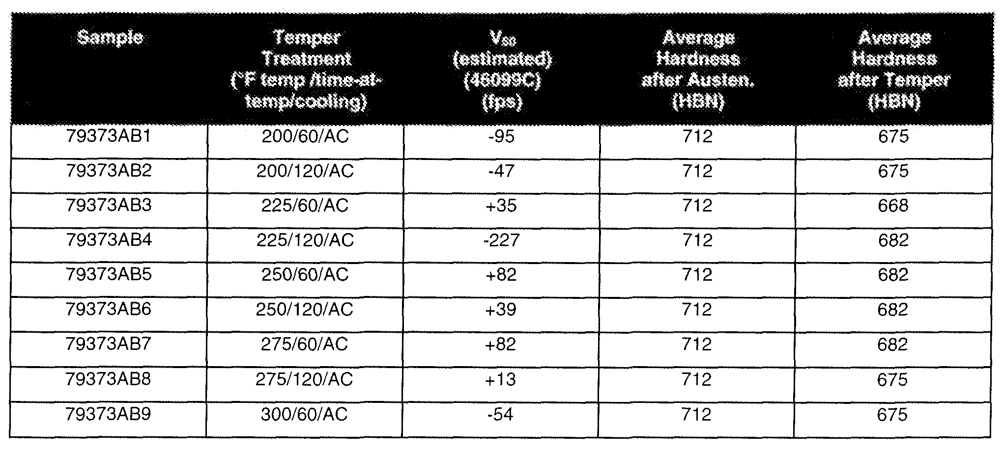
- Table 11 lists hardnesses and V 50 results for still air-cooled samples arranged horizontally on the cooling rack and stacked in contact with adjacent samples so as to influence the rate at which the samples cooled from the austenitizing temperature.
- the V 50 values included in Table 1 1 are plotted as a function of tempering practice in Figure 6.
- Four different stacking arrangements were used for the samples of Table 11. In one arrangement, shown on the top portion of Figure 5, two samples were placed in contact with one another. In another arrangement, shown in the bottom portion of Figure 5, three samples were placed in contact with one another.
- Figure 8 is a plot of the cooling curves for the samples stacked as shown in the top and bottom portions of Figure 5.
- Figure 7 shows two additional stacking arrangements wherein either four plates (top portion) or five plates (bottom portion) were placed in contact with one another while cooling from the austenitizing temperature.
- Figure 9 is a plot of the cooling curves for the samples stacked as shown in the top and bottom portions of Figure 7. For each sample listed in Table 11 , the second column of the table indicates the total number of samples associated in the stacking arrangement. It is expected that circulating air around the samples (versus, cooling in still air) and placing differing number of samples in contact with one another, as with the samples in Tables 9, 10, and 11 , influenced the shape of the cooling curves for the various samples.
- the particular paths followed by the cooling curves differed for the various arrangements of samples in Tables 9, 10, and 11.
- the cooling rate in one or more regions of the cooling curve for a sample cooled in contact with other samples may be less than the cooling rate for a vertically racked, spaced-apart sample in the same cooling curve region. It is believed that the differences in cooling of the samples resulted in microstructural differences in the samples that unexpectedly influenced the ballistic penetration resistance of the samples, as discussed below.
- Tables 9-11 identify the tempering treatment used with each sample listed in those tables.
- the V 50 results in Tables 9-11 are listed as a difference in feet/second (fps) relative to the required minimum V 50 velocity for the particular test sample size under specification MIL-A-46099C.
- a value of "-156” means that the V 50 for the sample, evaluated per the military specification using 7.62 mm (.30 caliber) armor piercing ammunition, was 156 fps less than the required value under the military specification
- a value of "+82” means that the V 50 velocity exceeded the required value by 82 fps.
- large, positive difference values are most desirable as they reflect ballistic penetration resistance that exceeds the required V 50 under the military specification.
- the V 50 values reported in Table 9 were estimated since the target plates cracked (degraded) during the ballistic testing. Ballistic results of samples listed in Tables 9 and 10 experienced a higher incidence of cracking.
- V 50 velocity for the samples under MIL-A-46099C V 50 velocity for the samples under MIL-A-46099C.
- the experimental data in Table 11 shows that embodiments of steel armors according to the present disclosure have V 50 velocities that approach or exceed the required values under MIL-A-46099C.
- the average V 50 listed in Table 10 for the samples cooled at a higher rate was only 2 fps greater than that required under the specification, and the samples experienced unacceptable multi-hit crack resistance.
- V 50 velocity requirements of MIL-A-46099C are approximately 300-400 fps greater than under specification MIL-DTL-461000E, certain steel armor embodiments according to the present disclosure will also approach or meet the required values under MIL-DTL- 46100E.
- the V 50 velocities preferably are no less than 150 ft/sec less than the required values under MIL-A-46099C. In other words, the V 50 velocities preferably are at least as great as a V 50 150 ft/sec less than the required V 50 under specification MIL-A-46099C with minimal crack propagation
- the average penetration resistance performance of the embodiments of Table 11 is substantial and is believed to be at least comparable to certain more costly high alloy armor materials, or K- 12 ® dual hardness armor plate.
- the steel armor samples in Table 11 had significantly lower surface hardness than the samples in Tables 9 and 10, they unexpectedly demonstrated substantially greater ballistic penetration resistance, with reduced incidence to crack propagation, and is comparable to ballistic resistance of certain premium, high alloy armor alloys.
- cooling curve was modified from that of a conventional air quench step by placing the samples in contact with one another in a horizontal orientation on the cooling rack, based on the inventors' observations discussed herein it is believed that other means of modifying the conventional cooling curve may be used to beneficially influence the ballistic performance of the alloys according to the present disclosure.
- examples of possible ways to beneficially modify the cooling curve of the alloys include cooling from the austenitizing temperature in a controlled cooling zone or covering the alloy with a thermally insulating material such as, for example, Kaowool material, during all or a portion of the step of cooling the alloy from the austenitizing temperature.
- low alloy steels according to the present disclosure preferably have hardness of at least 550 HBN.
- steels according to the present invention preferably have hardness that is greater than 550 HBN and less than 700 HBN, and more preferably is greater than 550 HBN and less than 675.
- steels according to the present disclosure have hardness that is at least 600 HBN and is less than 675 HBN. Hardness likely plays an important role in establishing ballistic performance.
- the experimental armor alloys produced according to the present methods also derive their unexpected substantial penetration resistance from microstructural changes resulting from the unconventional manner of cooling the samples, which modified the samples' cooling curves from a curve characterizing a conventional step of cooling samples from austenitizing temperature in air. b. Trial 2
- a first thermocouple (referred to as "channel 1") was positioned on the face of the middle sample (DA-8) of the racked samples.
- a second thermocouple (channel 2) was positioned on the outside face (i.e., not facing the middle plate) of an outer plate (DA-7).
- DA-7 outer plate
- a first thermocouple (channel 3) was disposed on the top surface of the bottom sample, and a second thermocouple (channel 4) was disposed on the bottom surface of the top sample (opposite the top surface of the middle sample).
- the cooling curve shown in Figure 12 plots sample temperature recorded at each of channels 1-4 from a time just after the samples were removed from the austenitizing furnace until reaching a temperature in the range of about 200-400oF (93-204oC).
- Figure 12 also shows a possible continuous cooling transformation (CCT) curve for the alloy, illustrating various phase regions for the alloy as it cools from high temperature.
- CCT continuous cooling transformation
- Figure 13 shows a detailed view of a portion of the cooling curve of Figure 1 1 including the region in which each of the cooling curves for channels 1 -4 intersect the theoretical CCT curve.
- Figure 14 shows a portion of the cooling curve and CCT curves shown in Figure 12, in the 500-900oF (260-482oC) sample temperature range.
- the cooling curves for channels 1 and 2 are similar to the curves for channels 3 and 4 (the stacked samples). However, the curves for channels 1 and 2 follow different paths than the curves for channels 3 and 4, and especially so in the early portion of the cooling curves (during the beginning of the cooling step). Subsequently, the shapes of the curves for channels 1 and 2 reflect a faster cooling rate than for channels 3 and 4.
- the cooling rate for channels 1 and 2 was approximately 136°F/min (75.6°C/min), and for channels 3 and 4 (stacked samples) were approximately 98°F/min (54.4°C/min) and approximately 107°F/min (59.4°C/min), respectively.
- the cooling rates for channels 3 and 4 fall between the cooling rates measured for the cooling trials involving two stacked plates (111 °F/min (61.7°C/min)) and 5 stacked plates (95°F/min (52.8°C/min)), discussed above.
- the cooling curves for the two stacked plate (“2Pl”) and 5 stacked plate (“5Pl”) cooling trials also are shown in Figures 12-14.
- Steel armors according to the present disclosure would provide substantial value inasmuch as they can exhibit ballistic performance at least commensurate with premium, high alloy armor alloys, while including substantially lower levels of costly alloying ingredients such as, for example, nickel, molybdenum, and chromium. Given the performance and cost advantages of embodiments of steel armors according to the present disclosure, it is believed that such armors are a very substantial advance over many existing armor alloys.
- the alloys plate and other mill products made according to the present disclosure may be used in conventional armor applications.
- Such applications include, for example, armored sheathing and other components for combat vehicles, armaments, armored doors and enclosures, and other article of manufacture requiring or benefiting from protection from projectile strikes, explosive blasts, and other high energy insults.
- These examples of possible applications for alloys according to the present disclosure are offered by way of example only, and are not exhaustive of all applications to which the present alloys may be applied.
- Those having ordinary skill, upon reading the present disclosure will readily identify additional applications for the alloys described herein. It is believed that those having ordinary skill in the art will be capable of fabricating all such articles of manufacture from alloys according to the present disclosure based on knowledge existing within the art. Accordingly, further discussion of fabrication procedures for such articles of manufacture is unnecessary here.
Landscapes
- Chemical & Material Sciences (AREA)
- Engineering & Computer Science (AREA)
- Materials Engineering (AREA)
- Mechanical Engineering (AREA)
- Metallurgy (AREA)
- Organic Chemistry (AREA)
- Crystallography & Structural Chemistry (AREA)
- Thermal Sciences (AREA)
- Physics & Mathematics (AREA)
- Heat Treatment Of Articles (AREA)
- Heat Treatment Of Steel (AREA)
- Aiming, Guidance, Guns With A Light Source, Armor, Camouflage, And Targets (AREA)
- Powder Metallurgy (AREA)
Abstract
Description


Claims
Priority Applications (14)
| Application Number | Priority Date | Filing Date | Title |
|---|---|---|---|
| AU2008283824A AU2008283824B2 (en) | 2007-08-01 | 2008-08-01 | High hardness, high toughness iron-base alloys and methods for making same |
| KR1020107004727A KR101873582B1 (en) | 2007-08-01 | 2008-08-01 | High hardness, high toughness iron-base alloys and methods for making same |
| CN2008801095266A CN101809181B (en) | 2007-08-01 | 2008-08-01 | H hardness, high toughness iron-base alloys and methods for making same |
| ES08826748.9T ES2666697T3 (en) | 2007-08-01 | 2008-08-01 | Alloys based on iron, high toughness and high hardness and method for manufacturing |
| CA2694052A CA2694052C (en) | 2007-08-01 | 2008-08-01 | High hardness, high toughness iron-base alloys and methods for making same |
| EP08826748.9A EP2183401B1 (en) | 2007-08-01 | 2008-08-01 | High hardness, high toughness iron-base alloys and method for making same |
| JP2010520225A JP5432900B2 (en) | 2007-08-01 | 2008-08-01 | High hardness, high toughness iron base alloy and method for producing the same |
| NO08826748A NO2183401T3 (en) | 2007-08-01 | 2008-08-01 | |
| MX2010000967A MX2010000967A (en) | 2007-08-01 | 2008-08-01 | High hardness, high toughness iron-base alloys and methods for making same. |
| RU2010107249/02A RU2481417C2 (en) | 2007-08-01 | 2008-08-01 | High-strength high-ductility iron-based alloys and methods of their production |
| PL08826748T PL2183401T3 (en) | 2007-08-01 | 2008-08-01 | High hardness, high toughness iron-base alloys and method for making same |
| BRPI0814141A BRPI0814141A8 (en) | 2007-08-01 | 2008-08-01 | IRON-BASED ALLOYS WITH HIGH HARDNESS AND STRENGTH, ROUND SHIELD PRODUCT, ARTICLE OF MANUFACTURING COMPRISING SUCH ALLOY AND METHOD FOR MANUFACTURING A ROUND SHIELD PRODUCT |
| KR1020157032798A KR20150133863A (en) | 2007-08-01 | 2008-08-01 | High hardness, high toughness iron-base alloys and methods for making same |
| DK08826748.9T DK2183401T3 (en) | 2007-08-01 | 2008-08-01 | Iron-based alloys with high hardness and high toughness, and methods for making them |
Applications Claiming Priority (2)
| Application Number | Priority Date | Filing Date | Title |
|---|---|---|---|
| US95326907P | 2007-08-01 | 2007-08-01 | |
| US60/953,269 | 2007-08-01 |
Publications (1)
| Publication Number | Publication Date |
|---|---|
| WO2009018522A1 true WO2009018522A1 (en) | 2009-02-05 |
Family
ID=39865176
Family Applications (1)
| Application Number | Title | Priority Date | Filing Date |
|---|---|---|---|
| PCT/US2008/071931 Ceased WO2009018522A1 (en) | 2007-08-01 | 2008-08-01 | High hardness, high toughness iron-base alloys and methods for making same |
Country Status (15)
| Country | Link |
|---|---|
| US (2) | US9121088B2 (en) |
| EP (1) | EP2183401B1 (en) |
| JP (1) | JP5432900B2 (en) |
| KR (2) | KR20150133863A (en) |
| CN (1) | CN101809181B (en) |
| AU (1) | AU2008283824B2 (en) |
| BR (1) | BRPI0814141A8 (en) |
| CA (1) | CA2694052C (en) |
| DK (1) | DK2183401T3 (en) |
| ES (1) | ES2666697T3 (en) |
| MX (1) | MX2010000967A (en) |
| NO (1) | NO2183401T3 (en) |
| PL (1) | PL2183401T3 (en) |
| RU (1) | RU2481417C2 (en) |
| WO (1) | WO2009018522A1 (en) |
Cited By (7)
| Publication number | Priority date | Publication date | Assignee | Title |
|---|---|---|---|---|
| EP2093304A1 (en) * | 2008-02-20 | 2009-08-26 | Benteler Automobiltechnik GmbH | Armour for a vehicle |
| WO2011049755A1 (en) * | 2009-10-19 | 2011-04-28 | Ati Properties, Inc. | High hardness, high toughness iron-base alloys and methods for making same |
| US20120174760A1 (en) * | 2011-01-07 | 2012-07-12 | Ati Properties, Inc. | Dual hardness steel article and method of making |
| JP2013505836A (en) * | 2009-09-24 | 2013-02-21 | エイティーアイ・プロパティーズ・インコーポレーテッド | Process for reducing flatness errors in alloy articles |
| US9121088B2 (en) | 2007-08-01 | 2015-09-01 | Ati Properties, Inc. | High hardness, high toughness iron-base alloys and methods for making same |
| US9657363B2 (en) | 2011-06-15 | 2017-05-23 | Ati Properties Llc | Air hardenable shock-resistant steel alloys, methods of making the alloys, and articles including the alloys |
| EP3754290B1 (en) | 2019-06-17 | 2022-05-11 | Benteler Automobiltechnik GmbH | Method for manufacturing an armored component for motor vehicles |
Families Citing this family (8)
| Publication number | Priority date | Publication date | Assignee | Title |
|---|---|---|---|---|
| US9835416B1 (en) * | 2010-04-12 | 2017-12-05 | The United States Of America, As Represented By The Secretary Of The Navy | Multi-ply heterogeneous armor with viscoelastic layers |
| US9499890B1 (en) | 2012-04-10 | 2016-11-22 | The United States Of America As Represented By The Secretary Of The Navy | High-strength, high-toughness steel articles for ballistic and cryogenic applications, and method of making thereof |
| CN105369150B (en) * | 2014-08-27 | 2017-03-15 | 宝钢特钢有限公司 | A kind of superhigh intensity armor manufacture method |
| CN104894483B (en) * | 2015-05-15 | 2018-07-31 | 安泰科技股份有限公司 | Powder metallurgy wear resistant tools steel |
| GB2546808B (en) * | 2016-02-01 | 2018-09-12 | Rolls Royce Plc | Low cobalt hard facing alloy |
| GB2546809B (en) * | 2016-02-01 | 2018-05-09 | Rolls Royce Plc | Low cobalt hard facing alloy |
| CN107310218B (en) * | 2016-04-26 | 2019-03-29 | 宝山钢铁股份有限公司 | A kind of composite bulletproof steel plate and its manufacturing method |
| CN107310219B (en) * | 2016-04-26 | 2019-03-29 | 宝山钢铁股份有限公司 | A kind of bulletproof steel plate with excellent cold bending performance and its manufacturing method |
Citations (5)
| Publication number | Priority date | Publication date | Assignee | Title |
|---|---|---|---|---|
| GB874488A (en) * | 1958-08-11 | 1961-08-10 | Henri Georges Bouly | Steel alloys |
| FR2106939A5 (en) * | 1970-09-30 | 1972-05-05 | Creusot Forges Ateliers | Weldable clad steel sheet - for armour plate |
| SU404889A2 (en) * | 1972-05-24 | 1973-10-22 | ||
| US5122336A (en) * | 1989-10-09 | 1992-06-16 | Creusot-Loire Industrie | High hardness steel for armouring and process for the production of such a steel |
| EP0731332A2 (en) * | 1995-03-06 | 1996-09-11 | Allegheny Ludlum Corporation | Ballistic resistant metal armor plate |
Family Cites Families (71)
| Publication number | Priority date | Publication date | Assignee | Title |
|---|---|---|---|---|
| US1016560A (en) | 1906-09-06 | 1912-02-06 | Anonima Italiano Gio Ansaldo Armstrong & Co Soc | Armor-plate and other steel article. |
| US1563420A (en) | 1921-08-08 | 1925-12-01 | John B Johnson | Process of manufacture of armor plate |
| US2249629A (en) | 1938-03-02 | 1941-07-15 | Kellogg M W Co | Armored article |
| US2562467A (en) | 1946-05-14 | 1951-07-31 | United States Steel Corp | Armor plate and method for making same |
| GB763442A (en) | 1952-04-03 | 1956-12-12 | Wilbur Thomas Bolkcom | Improvements in or relating to low alloy steels and a method of manufacturing them |
| US3379582A (en) | 1967-02-15 | 1968-04-23 | Harry J. Dickinson | Low-alloy high-strength steel |
| US3785801A (en) | 1968-03-01 | 1974-01-15 | Int Nickel Co | Consolidated composite materials by powder metallurgy |
| JPS499899A (en) | 1972-04-26 | 1974-01-28 | ||
| US3888637A (en) | 1972-12-29 | 1975-06-10 | Komatsu Mfg Co Ltd | Ripper point part |
| US3944442A (en) | 1973-07-13 | 1976-03-16 | The International Nickel Company, Inc. | Air hardenable, formable steel |
| SU685711A1 (en) | 1975-02-07 | 1979-09-15 | Азербайджанский Политехнический Институт Им. Ч.Ильдрыма | Structural steel |
| DE7920376U1 (en) | 1979-07-17 | 1980-01-31 | Industrie-Werke Karlsruhe Augsburg Ag, 7500 Karlsruhe | BALLISTIC AND / OR SPLITTER PROTECTION |
| JPS5741351A (en) | 1980-08-27 | 1982-03-08 | Kobe Steel Ltd | Super-hightensile steel |
| US4443254A (en) | 1980-10-31 | 1984-04-17 | Inco Research & Development Center, Inc. | Cobalt free maraging steel |
| JPS5783575A (en) | 1980-11-11 | 1982-05-25 | Fuji Fiber Glass Kk | Friction material |
| JPS604884B2 (en) | 1981-03-30 | 1985-02-07 | 科学技術庁金属材料技術研究所所 | Manufacturing method of super strong Kamalage steel |
| FR2509640A1 (en) | 1981-07-17 | 1983-01-21 | Creusot Loire | PROCESS FOR PRODUCING A COMPOSITE METAL PART AND PRODUCTS OBTAINED |
| JPS58157950A (en) | 1982-03-11 | 1983-09-20 | Kobe Steel Ltd | High tensile steel for extralow temperature use |
| JPS58199846A (en) | 1982-05-18 | 1983-11-21 | Kobe Steel Ltd | Superhigh tensile steel |
| JPS596356A (en) | 1982-06-30 | 1984-01-13 | Kobe Steel Ltd | Ultra-high tensile steel |
| JPS5947363A (en) | 1982-09-01 | 1984-03-17 | Hitachi Metals Ltd | Co-free maraging steel with superior delayed rupture characteristic |
| JPS6029446A (en) | 1983-07-28 | 1985-02-14 | Riken Seikou Kk | Alloy steel for precision plastic die parts |
| DE3340031C2 (en) | 1983-11-05 | 1985-11-21 | Thyssen Stahl AG, 4100 Duisburg | Armored sheet metal and process for its manufacture |
| JPS60230693A (en) | 1984-04-27 | 1985-11-16 | インタ−ナショナル ビジネス マシ−ンズ コ−ポレ−ション | Color image display system |
| DE3628395C1 (en) | 1986-08-21 | 1988-03-03 | Thyssen Edelstahlwerke Ag | Use of steel for plastic molds |
| US4832909A (en) | 1986-12-22 | 1989-05-23 | Carpenter Technology Corporation | Low cobalt-containing maraging steel with improved toughness |
| DE3742539A1 (en) | 1987-12-16 | 1989-07-06 | Thyssen Stahl Ag | METHOD FOR PRODUCING PLATED WARM RIBBON AND FOLLOWING PRODUCED PLATED WARM RIBBON |
| US4871511A (en) | 1988-02-01 | 1989-10-03 | Inco Alloys International, Inc. | Maraging steel |
| JPH01296098A (en) | 1988-05-24 | 1989-11-29 | Seiko:Kk | Protective board |
| US4941927A (en) | 1989-04-26 | 1990-07-17 | The United States Of America As Represented By The Secretary Of The Army | Fabrication of 18% Ni maraging steel laminates by roll bonding |
| US5268044A (en) | 1990-02-06 | 1993-12-07 | Carpenter Technology Corporation | High strength, high fracture toughness alloy |
| JPH0426738A (en) | 1990-05-19 | 1992-01-29 | Sumitomo Metal Ind Ltd | Steel for hot tube manufacturing tool and hot tube manufacturing tool thereof |
| JPH0426739A (en) | 1990-05-19 | 1992-01-29 | Sumitomo Metal Ind Ltd | Steel for hot tube manufacturing tool and hot tube manufacturing tool thereof |
| US5180450A (en) | 1990-06-05 | 1993-01-19 | Ferrous Wheel Group Inc. | High performance high strength low alloy wrought steel |
| DD295195A5 (en) | 1990-06-11 | 1991-10-24 | Gisag Ag,Giesserei Und Maschinenbau Leipzig,De | WEAR-RESISTANT STEEL ALLOY |
| JP2510783B2 (en) | 1990-11-28 | 1996-06-26 | 新日本製鐵株式会社 | Method for producing clad steel sheet with excellent low temperature toughness |
| FR2690166A1 (en) | 1992-04-16 | 1993-10-22 | Creusot Loire | A method of manufacturing a plated sheet having an abrasion-resistant layer of tool steel and plated sheet obtained. |
| US5332545A (en) | 1993-03-30 | 1994-07-26 | Rmi Titanium Company | Method of making low cost Ti-6A1-4V ballistic alloy |
| US6087013A (en) | 1993-07-14 | 2000-07-11 | Harsco Technologies Corporation | Glass coated high strength steel |
| JPH07173573A (en) | 1993-12-17 | 1995-07-11 | Kobe Steel Ltd | Free-cutting steel excellent in machinability by carbide tool and internal quality |
| DE4344879C2 (en) | 1993-12-29 | 1997-08-07 | G & S Tech Gmbh Schutz Und Sic | Composite steel for the protection of vehicles, process for its production and use as a vehicle trim part |
| RU2090828C1 (en) | 1994-06-24 | 1997-09-20 | Леонид Александрович Кирель | Bulletproof heterogeneous armor of alloyed steel for means of personal protection and method of its production |
| US5720829A (en) | 1995-03-08 | 1998-02-24 | A. Finkl & Sons Co. | Maraging type hot work implement or tool and method of manufacture thereof |
| RU2102688C1 (en) * | 1996-02-20 | 1998-01-20 | Чивилев Владимир Васильевич | Multilayer armor barrier |
| US5866066A (en) | 1996-09-09 | 1999-02-02 | Crs Holdings, Inc. | Age hardenable alloy with a unique combination of very high strength and good toughness |
| FR2774099B1 (en) | 1998-01-23 | 2000-02-25 | Imphy Sa | STEEL MARAGING WITHOUT COBALT |
| JP2000031397A (en) | 1998-07-10 | 2000-01-28 | Toshiba Corp | Semiconductor device |
| RU2139357C1 (en) * | 1999-04-14 | 1999-10-10 | Бащенко Анатолий Павлович | Method of manufacture of steel monosheet armored members b 100 st |
| DE19921961C1 (en) | 1999-05-11 | 2001-02-01 | Dillinger Huettenwerke Ag | Process for producing a composite steel sheet, in particular for protecting vehicles against shelling |
| DE19961948A1 (en) | 1999-12-22 | 2001-06-28 | Dillinger Huettenwerke Ag | Composite steel sheet, in particular for protecting vehicles against shelling |
| DE10128544C2 (en) | 2001-06-13 | 2003-06-05 | Thyssenkrupp Stahl Ag | High-strength, cold-workable sheet steel, process for its production and use of such a sheet |
| US7926180B2 (en) | 2001-06-29 | 2011-04-19 | Mccrink Edward J | Method for manufacturing gas and liquid storage tanks |
| US7475478B2 (en) | 2001-06-29 | 2009-01-13 | Kva, Inc. | Method for manufacturing automotive structural members |
| FR2838138B1 (en) | 2002-04-03 | 2005-04-22 | Usinor | STEEL FOR THE MANUFACTURE OF PLASTIC INJECTION MOLDS OR FOR THE MANUFACTURE OF WORKPIECES FOR METAL WORKING |
| JP4430284B2 (en) | 2002-07-23 | 2010-03-10 | 新日本製鐵株式会社 | Steel material with few alumina clusters |
| FR2847271B1 (en) | 2002-11-19 | 2004-12-24 | Usinor | METHOD FOR MANUFACTURING AN ABRASION RESISTANT STEEL SHEET AND OBTAINED SHEET |
| ATE477350T1 (en) | 2003-01-24 | 2010-08-15 | Ellwood Nat Forge Company | EGLIN STEEL- A LOW ALLOY HIGH STRENGTH COMPOSITION |
| WO2004111277A1 (en) | 2003-06-12 | 2004-12-23 | Nippon Steel Corporation | Steel product reduced in alumina cluster |
| UA84607C2 (en) | 2005-05-12 | 2008-11-10 | Индустель Крюзо | STEEL OF HIGH mechanical strength AND wear-resistance |
| EP1951923B1 (en) | 2005-08-30 | 2016-12-07 | ATI Properties LLC | Steel compositions, methods of forming the same, and articles formed therefrom |
| RU2297460C1 (en) | 2006-04-05 | 2007-04-20 | Закрытое акционерное общество "Ижевский опытно-механический завод" | Method for making elongated, mainly cylindrical product of construction high-strength steel, product of construction high-strength steel |
| JP4150054B2 (en) | 2006-06-21 | 2008-09-17 | 株式会社神戸製鋼所 | FORGING STEEL, PROCESS FOR PRODUCING THE SAME AND FORGED PRODUCT |
| CN100503893C (en) | 2006-10-13 | 2009-06-24 | 燕山大学 | Manufacturing process of gears with hard bainite structure on the surface |
| KR20150133863A (en) | 2007-08-01 | 2015-11-30 | 에이티아이 프로퍼티즈, 인코퍼레이티드 | High hardness, high toughness iron-base alloys and methods for making same |
| US8444776B1 (en) | 2007-08-01 | 2013-05-21 | Ati Properties, Inc. | High hardness, high toughness iron-base alloys and methods for making same |
| US8529708B2 (en) | 2007-10-22 | 2013-09-10 | Jay Carl Locke | Carburized ballistic alloy |
| RU2388986C2 (en) | 2008-05-14 | 2010-05-10 | ЗАО "ФОРТ Технология" | Multilayer armored barrier (versions) |
| US9822422B2 (en) | 2009-09-24 | 2017-11-21 | Ati Properties Llc | Processes for reducing flatness deviations in alloy articles |
| CN101906588B (en) | 2010-07-09 | 2011-12-28 | 清华大学 | Preparation method for air-cooled lower bainite/martensite multi-phase wear-resistant cast steel |
| US9182196B2 (en) | 2011-01-07 | 2015-11-10 | Ati Properties, Inc. | Dual hardness steel article |
| US9657363B2 (en) | 2011-06-15 | 2017-05-23 | Ati Properties Llc | Air hardenable shock-resistant steel alloys, methods of making the alloys, and articles including the alloys |
-
2008
- 2008-08-01 KR KR1020157032798A patent/KR20150133863A/en not_active Ceased
- 2008-08-01 PL PL08826748T patent/PL2183401T3/en unknown
- 2008-08-01 ES ES08826748.9T patent/ES2666697T3/en active Active
- 2008-08-01 CN CN2008801095266A patent/CN101809181B/en not_active Expired - Fee Related
- 2008-08-01 DK DK08826748.9T patent/DK2183401T3/en active
- 2008-08-01 BR BRPI0814141A patent/BRPI0814141A8/en not_active Application Discontinuation
- 2008-08-01 JP JP2010520225A patent/JP5432900B2/en not_active Expired - Fee Related
- 2008-08-01 KR KR1020107004727A patent/KR101873582B1/en not_active Expired - Fee Related
- 2008-08-01 AU AU2008283824A patent/AU2008283824B2/en not_active Ceased
- 2008-08-01 WO PCT/US2008/071931 patent/WO2009018522A1/en not_active Ceased
- 2008-08-01 US US12/184,573 patent/US9121088B2/en not_active Expired - Fee Related
- 2008-08-01 RU RU2010107249/02A patent/RU2481417C2/en not_active IP Right Cessation
- 2008-08-01 EP EP08826748.9A patent/EP2183401B1/en not_active Not-in-force
- 2008-08-01 CA CA2694052A patent/CA2694052C/en not_active Expired - Fee Related
- 2008-08-01 MX MX2010000967A patent/MX2010000967A/en active IP Right Grant
- 2008-08-01 NO NO08826748A patent/NO2183401T3/no unknown
-
2015
- 2015-07-21 US US14/804,391 patent/US9951404B2/en not_active Expired - Fee Related
Patent Citations (5)
| Publication number | Priority date | Publication date | Assignee | Title |
|---|---|---|---|---|
| GB874488A (en) * | 1958-08-11 | 1961-08-10 | Henri Georges Bouly | Steel alloys |
| FR2106939A5 (en) * | 1970-09-30 | 1972-05-05 | Creusot Forges Ateliers | Weldable clad steel sheet - for armour plate |
| SU404889A2 (en) * | 1972-05-24 | 1973-10-22 | ||
| US5122336A (en) * | 1989-10-09 | 1992-06-16 | Creusot-Loire Industrie | High hardness steel for armouring and process for the production of such a steel |
| EP0731332A2 (en) * | 1995-03-06 | 1996-09-11 | Allegheny Ludlum Corporation | Ballistic resistant metal armor plate |
Cited By (24)
| Publication number | Priority date | Publication date | Assignee | Title |
|---|---|---|---|---|
| US9121088B2 (en) | 2007-08-01 | 2015-09-01 | Ati Properties, Inc. | High hardness, high toughness iron-base alloys and methods for making same |
| US9951404B2 (en) | 2007-08-01 | 2018-04-24 | Ati Properties Llc | Methods for making high hardness, high toughness iron-base alloys |
| US8444776B1 (en) | 2007-08-01 | 2013-05-21 | Ati Properties, Inc. | High hardness, high toughness iron-base alloys and methods for making same |
| US9593916B2 (en) | 2007-08-01 | 2017-03-14 | Ati Properties Llc | High hardness, high toughness iron-base alloys and methods for making same |
| EP2093304A1 (en) * | 2008-02-20 | 2009-08-26 | Benteler Automobiltechnik GmbH | Armour for a vehicle |
| US10260120B2 (en) | 2009-09-24 | 2019-04-16 | Ati Properties Llc | Processes for reducing flatness deviations in alloy articles |
| JP2013505836A (en) * | 2009-09-24 | 2013-02-21 | エイティーアイ・プロパティーズ・インコーポレーテッド | Process for reducing flatness errors in alloy articles |
| US9822422B2 (en) | 2009-09-24 | 2017-11-21 | Ati Properties Llc | Processes for reducing flatness deviations in alloy articles |
| KR101874271B1 (en) * | 2009-10-19 | 2018-07-03 | 에이티아이 프로퍼티즈 엘엘씨 | High hardness, high toughness iron-base alloys and methods for making same |
| CN102686753A (en) * | 2009-10-19 | 2012-09-19 | Ati资产公司 | Iron-based alloy with high hardness and high toughness and preparation method thereof |
| CN104805373A (en) * | 2009-10-19 | 2015-07-29 | Ati资产公司 | High hardness, high toughness iron-base alloys and methods for making same |
| RU2551737C2 (en) * | 2009-10-19 | 2015-05-27 | ЭйТиАй ПРОПЕРТИЗ, ИНК. | Alloys based on iron with high hardness, strength and method of their manufacturing |
| CN102686753B (en) * | 2009-10-19 | 2015-06-10 | Ati资产公司 | Iron-based alloy with high hardness and high toughness and preparation method thereof |
| AU2010308415B2 (en) * | 2009-10-19 | 2014-05-15 | Ati Properties, Inc. | High hardness, high toughness iron-base alloys and methods for making same |
| WO2011049755A1 (en) * | 2009-10-19 | 2011-04-28 | Ati Properties, Inc. | High hardness, high toughness iron-base alloys and methods for making same |
| KR101745743B1 (en) * | 2009-10-19 | 2017-06-12 | 에이티아이 프로퍼티즈 엘엘씨 | High hardness, high toughness iron-base alloys and methods for making same |
| JP2013508542A (en) * | 2009-10-19 | 2013-03-07 | エイティーアイ・プロパティーズ・インコーポレーテッド | High-hardness and high-toughness iron-based alloy and method for producing the same |
| US9182196B2 (en) | 2011-01-07 | 2015-11-10 | Ati Properties, Inc. | Dual hardness steel article |
| US20120174760A1 (en) * | 2011-01-07 | 2012-07-12 | Ati Properties, Inc. | Dual hardness steel article and method of making |
| US10113211B2 (en) | 2011-01-07 | 2018-10-30 | Ati Properties Llc | Method of making a dual hardness steel article |
| US10858715B2 (en) | 2011-01-07 | 2020-12-08 | Ati Properties Llc | Dual hardness steel article |
| AU2016238855B2 (en) * | 2011-06-15 | 2018-11-08 | Ati Properties Llc | Air hardenable shock-resistant steel alloys, methods of making the alloys, and articles including the alloys |
| US9657363B2 (en) | 2011-06-15 | 2017-05-23 | Ati Properties Llc | Air hardenable shock-resistant steel alloys, methods of making the alloys, and articles including the alloys |
| EP3754290B1 (en) | 2019-06-17 | 2022-05-11 | Benteler Automobiltechnik GmbH | Method for manufacturing an armored component for motor vehicles |
Also Published As
| Publication number | Publication date |
|---|---|
| US9951404B2 (en) | 2018-04-24 |
| KR101873582B1 (en) | 2018-08-02 |
| RU2010107249A (en) | 2011-09-10 |
| PL2183401T3 (en) | 2018-08-31 |
| BRPI0814141A2 (en) | 2015-02-03 |
| JP2010535292A (en) | 2010-11-18 |
| US20150322554A1 (en) | 2015-11-12 |
| ES2666697T3 (en) | 2018-05-07 |
| US9121088B2 (en) | 2015-09-01 |
| MX2010000967A (en) | 2010-03-09 |
| KR20100059832A (en) | 2010-06-04 |
| KR20150133863A (en) | 2015-11-30 |
| US20120183430A1 (en) | 2012-07-19 |
| JP5432900B2 (en) | 2014-03-05 |
| RU2481417C2 (en) | 2013-05-10 |
| DK2183401T3 (en) | 2018-05-07 |
| AU2008283824A1 (en) | 2009-02-05 |
| EP2183401B1 (en) | 2018-03-07 |
| BRPI0814141A8 (en) | 2017-04-04 |
| EP2183401A1 (en) | 2010-05-12 |
| NO2183401T3 (en) | 2018-08-04 |
| AU2008283824B2 (en) | 2012-04-12 |
| CN101809181A (en) | 2010-08-18 |
| CN101809181B (en) | 2013-11-13 |
| CA2694052A1 (en) | 2009-02-05 |
| CA2694052C (en) | 2016-09-27 |
Similar Documents
| Publication | Publication Date | Title |
|---|---|---|
| AU2008283824B2 (en) | High hardness, high toughness iron-base alloys and methods for making same | |
| CA2775348C (en) | High hardness, high toughness iron-base alloys and methods for making same | |
| AU2014203070B2 (en) | High hardness, high toughness iron-base alloys and methods for making same | |
| HK1144206B (en) | High hardness, high toughness iron-base alloys and method for making same | |
| HK1144206A (en) | High hardness, high toughness iron-base alloys and method for making same | |
| HK1212399B (en) | High hardness, high toughness iron-base alloys and methods for making same | |
| HK1175505B (en) | High hardness, high toughness iron-base alloys and methods for making same | |
| HK1191066B (en) | Air hardenable shock-resistant steel alloys, methods of making the alloys, and articles including the alloys |
Legal Events
| Date | Code | Title | Description |
|---|---|---|---|
| WWE | Wipo information: entry into national phase |
Ref document number: 200880109526.6 Country of ref document: CN |
|
| 121 | Ep: the epo has been informed by wipo that ep was designated in this application |
Ref document number: 08826748 Country of ref document: EP Kind code of ref document: A1 |
|
| WWE | Wipo information: entry into national phase |
Ref document number: 2008283824 Country of ref document: AU |
|
| WWE | Wipo information: entry into national phase |
Ref document number: 2694052 Country of ref document: CA |
|
| WWE | Wipo information: entry into national phase |
Ref document number: 203438 Country of ref document: IL |
|
| WWE | Wipo information: entry into national phase |
Ref document number: MX/A/2010/000967 Country of ref document: MX |
|
| WWE | Wipo information: entry into national phase |
Ref document number: 2010520225 Country of ref document: JP |
|
| NENP | Non-entry into the national phase |
Ref country code: DE |
|
| WWE | Wipo information: entry into national phase |
Ref document number: 801/DELNP/2010 Country of ref document: IN |
|
| ENP | Entry into the national phase |
Ref document number: 2008283824 Country of ref document: AU Date of ref document: 20080801 Kind code of ref document: A |
|
| WWE | Wipo information: entry into national phase |
Ref document number: 2008826748 Country of ref document: EP |
|
| WWE | Wipo information: entry into national phase |
Ref document number: 2010107249 Country of ref document: RU |
|
| ENP | Entry into the national phase |
Ref document number: 20107004727 Country of ref document: KR Kind code of ref document: A |
|
| ENP | Entry into the national phase |
Ref document number: PI0814141 Country of ref document: BR Kind code of ref document: A2 Effective date: 20100127 |