WO2009021407A1 - A method and device for modulating the information of tfci - Google Patents
A method and device for modulating the information of tfci Download PDFInfo
- Publication number
- WO2009021407A1 WO2009021407A1 PCT/CN2008/001463 CN2008001463W WO2009021407A1 WO 2009021407 A1 WO2009021407 A1 WO 2009021407A1 CN 2008001463 W CN2008001463 W CN 2008001463W WO 2009021407 A1 WO2009021407 A1 WO 2009021407A1
- Authority
- WO
- WIPO (PCT)
- Prior art keywords
- tfci information
- power point
- point
- tfci
- constellation
- Prior art date
- Legal status (The legal status is an assumption and is not a legal conclusion. Google has not performed a legal analysis and makes no representation as to the accuracy of the status listed.)
- Ceased
Links
Classifications
-
- H—ELECTRICITY
- H04—ELECTRIC COMMUNICATION TECHNIQUE
- H04L—TRANSMISSION OF DIGITAL INFORMATION, e.g. TELEGRAPHIC COMMUNICATION
- H04L27/00—Modulated-carrier systems
- H04L27/32—Carrier systems characterised by combinations of two or more of the types covered by groups H04L27/02, H04L27/10, H04L27/18 or H04L27/26
- H04L27/34—Amplitude- and phase-modulated carrier systems, e.g. quadrature-amplitude modulated carrier systems
-
- H—ELECTRICITY
- H04—ELECTRIC COMMUNICATION TECHNIQUE
- H04L—TRANSMISSION OF DIGITAL INFORMATION, e.g. TELEGRAPHIC COMMUNICATION
- H04L1/00—Arrangements for detecting or preventing errors in the information received
- H04L1/0001—Systems modifying transmission characteristics according to link quality, e.g. power backoff
- H04L1/0023—Systems modifying transmission characteristics according to link quality, e.g. power backoff characterised by the signalling
- H04L1/0025—Transmission of mode-switching indication
-
- H—ELECTRICITY
- H04—ELECTRIC COMMUNICATION TECHNIQUE
- H04L—TRANSMISSION OF DIGITAL INFORMATION, e.g. TELEGRAPHIC COMMUNICATION
- H04L1/00—Arrangements for detecting or preventing errors in the information received
- H04L1/0078—Avoidance of errors by organising the transmitted data in a format specifically designed to deal with errors, e.g. location
- H04L1/0079—Formats for control data
-
- H—ELECTRICITY
- H04—ELECTRIC COMMUNICATION TECHNIQUE
- H04L—TRANSMISSION OF DIGITAL INFORMATION, e.g. TELEGRAPHIC COMMUNICATION
- H04L27/00—Modulated-carrier systems
- H04L27/32—Carrier systems characterised by combinations of two or more of the types covered by groups H04L27/02, H04L27/10, H04L27/18 or H04L27/26
- H04L27/34—Amplitude- and phase-modulated carrier systems, e.g. quadrature-amplitude modulated carrier systems
- H04L27/3405—Modifications of the signal space to increase the efficiency of transmission, e.g. reduction of the bit error rate, bandwidth, or average power
- H04L27/3411—Modifications of the signal space to increase the efficiency of transmission, e.g. reduction of the bit error rate, bandwidth, or average power reducing the peak to average power ratio or the mean power of the constellation; Arrangements for increasing the shape gain of a signal set
Definitions
- the present invention relates to the field of communications, and in particular, to a method and apparatus for modulating TFCI information. Background technique
- MBMS Multimedia Broadcast and Multicast Service
- QAM quadrature amplitude modulation
- LCR TDD MBMS Low Chip Rate Time Division Duplex MBMS
- LCR TDD MBMS Low Chip Rate Time Division Duplex MBMS
- the four slot formats shown in Figure 1 can be used.
- the four slot formats set the size and composition domain of the data transmitted in each slot, and whether or not the setting is set.
- Transport Format Combination Indication (TFCI) information is carried in the transmitted data.
- the TFCI information is used to indicate a combination of data, for example, indicating that the first 20 bits of the 80 bits of data obtained by the receiver are the first group of data, and the last 60 bits are the second group of data.
- each time slot contains 5 ms, and transmitting one data frame requires two time slots, that is, 10 ms.
- a 10 ms data frame occupies a first time slot and a second time slot. If the data frame carries 8 bits of TFCI information, the TFCI information is divided into two parts, and The first partial TFCI information of 4 bits and the second partial TFCI information of 4 bits are placed at respective positions in the first time slot and the second time slot, respectively.
- the following takes the first time slot as an example.
- the data transmitted in the first time slot is divided into the first part data and the second part data.
- the first partial TFCI information is placed at the end of the first partial data in the first time slot; for the same reason, the second partial TFCI information is placed in the second time slot.
- the end of a portion of the data In this way, 8 bits of TFCI information can be transmitted to the receiver through the data frame.
- TTI transmission time interval
- the data length of the TFCI information is only 8 bits, which can be seen if the TFCI information is lost during transmission. If there is more, it is convenient to receive and cannot demodulate the corresponding data portion based on the obtained TFCI information.
- the LCR TDD 16QAM constellation there are 16 energy points. Each energy point is identified by a binary code with a data length of 4 bits. The intersection of the Q axis and the I axis of the coordinate axis is called the origin of the LCR TDD 16QAM constellation. The distance from the energy point to the origin is associated with the power it has, and the energy point that is further away from the origin has a higher power.
- the four energy points closest to the origin are called low energy points, also called minimum power points; the four energy points farthest from the origin are called high energy points, also called maximum power.
- the remaining eight energy points are called intermediate energy points, also known as intermediate power points.
- the modulated TFCI information may still fail to achieve the desired signal strength, thereby affecting the demodulation effect of the receiver; on the other hand, in the modulation process, there are multiple mappings of different TFCI information, in this case, If the number of times the TFCI information is mapped to the low energy point is significantly different from the number of times the TFCI information is mapped to the high energy point, a large peak-to-average ratio (ratio of the peak value to the average value) is generated in the system, which easily causes the system to be caused. The average power fluctuation in the system, which in turn affects the stability of the system. Summary of the invention
- the embodiment of the invention provides a modulation method and device for TFCI information, which not only ensures the demodulation performance of the modulated TFCI information, but also avoids the problem of average power fluctuation caused by the modulation of the TFCI information.
- a transmission format combination indicating a modulation method of TFCI information including the steps:
- the original TFCI information is equally divided in units of 2 bits; the TFCI information of each part after the equalization is extended to correspond to the identifier of at least one specified energy point in the preset constellation;
- the expanded portions of the TFCI information are mapped to corresponding energy points for modulation.
- a modulation apparatus for modulating a transport format combination indicating TFCI information comprising:
- a storage unit configured to store a preset constellation map
- An extension unit configured to divide the acquired original TFCI information in units of 2 bits in a transmission time interval, and extend the equalized portion of the TFCI information to at least one specified energy point in the preset constellation diagram Corresponding to the logo;
- a modulating unit configured to map the extended partial TFCI information to a corresponding energy point.
- each part of the TFCI information that is equally divided from the original TFCI information in units of 2 bits is extended to at least one specified energy point in the preset constellation diagram.
- the identification, and mapping the extended TFCI information to the corresponding energy point without offset so that the signal strength of the TFCI information in the system can be ensured, thereby ensuring the demodulation performance of the TFCI information, and Also avoids causing average power fluctuations in the system, from And to some extent, improve the stability of the system.
- FIG. 1 is a schematic diagram of a 16QAM slot format adopted by the LCR TDD MBMS in the prior art
- FIG. 2 is a schematic diagram of a data frame structure adopted by the LCR TDD MBMS in the prior art
- FIG. 3 is a LCR TDD 16QAM used in the prior art. Constellation;
- FIG. 4 is a first LCR TDD 16QAM constellation diagram used in the embodiment of the present invention
- FIG. 5 is a functional structural diagram of a first modulation apparatus according to an embodiment of the present invention
- 6A is a flowchart of a first method for modulating TFCI information according to an embodiment of the present invention
- 6B is a schematic structural diagram of a first data frame according to an embodiment of the present invention.
- FIG. 7A is a functional structural diagram of a second modulation apparatus according to an embodiment of the present invention.
- FIG. 7B is a flowchart of a second method for modulating TFCI information according to an embodiment of the present invention.
- FIG. 7C is a second LCR TDD 16QAM constellation diagram used in the embodiment of the present invention
- FIG. 8A is a functional structural diagram of a third modulation apparatus according to an embodiment of the present invention.
- 8B and 8C are third and fourth types of LCR TDD 16QAM used in the embodiment of the present invention.
- FIG. 9 is a flowchart of a third method for modulating TFCI information according to an embodiment of the present invention.
- FIG. 10 is a schematic structural diagram of a second data frame according to an embodiment of the present invention. detailed description
- the original TFCI information acquired in units of 2 bits is obtained in one TTI.
- the constellation is used to modulate TFCI information, and the specified energy point is not Include a minimum power point in the constellation diagram, where: if the number of specified energy points is greater than 1, all specified energy points have the same power;
- the expanded portions of the TFCI information are mapped to corresponding energy points for modulation.
- LCR TDD MBMS low-chip time division duplex multimedia broadcast and multicast service
- the original TFCI information with a data length of 8 bits is first expanded, and converted into a new data length of 16 bits.
- the original TFCI information is "00011011".
- the original TFCI information is first divided into four parts, namely "00", “01”, “10” and “11”, then refer to the table items d4k+2 and d4k+3 in Table 1, and then add 2bits of data at the end of each part of TFCI information, so that the data length of each group of TFCI information is extended from 2bits to 4bits, that is, conversion "0011",
- the original TFCI information with a data length of 8 bits is updated to a new TFCI information with a data length of 16 bits, namely "0011011110111111".
- the square of the distance between each energy point and the origin represents the magnitude of the signal power of the TFCI information mapped to the energy point, for example, the energy point 0101 and the origin. If the distance is a, then mapping a certain TFCI information to energy point 0101 without offset means that the signal power of the TFCI information is modulated to a 2 .
- the energy points in the LCR TDD 16QAM constellation are uniformly distributed in a square, and the diagonals of the square coincide with the Q axis and the I axis respectively.
- the energy points are identified as “0011", "0111
- the four energy points of ", “1011” and “1111” are equal to the distance from the origin and farthest from the origin with respect to other energy points, and therefore, are identified as “0011”, “0111”, “1011”, and “1111”
- the four energy points are high energy points, also called maximum power points, so if the TFCI information can be mapped to "0011", "0111” without offset, The four high energy points "1011” and “1111” can maintain the maximum signal power of the TFCI information, thereby ensuring the demodulation performance of the TFCI information.
- a modulation apparatus for modulating TFCI information includes a storage unit 50, an extension unit 51, and a modulation unit 52.
- the storage unit 50 is configured to store preset slot format information and an LCR TDD 16QAM constellation for modulating TFCI information.
- the extension unit 51 is configured to divide the acquired original TFCI information into four parts in units of 2 bits in the TTI, and separately expand the four parts of the TFCI information according to the LCR TDD 16QAM constellation map, so as to expand
- the four-part TFCI information respectively corresponds to the identification of four designated power points in the LCR TDD 16QAM constellation;
- the modulating unit 52 is configured to map the extended four-part TFCI information to corresponding power points in the LCR TDD 16QAM constellation. among them:
- the expansion unit 51 further includes a first determining unit 510 and a first processing unit 511.
- the first determining unit 510 is configured to determine that the specified energy point is the maximum power point in the LCR TDD 16QAM constellation;
- the first processing unit 511 is configured to expand the divided partial TFCI information to correspond to the identifier of the maximum power point.
- the detailed process of the first method for modulating the TFCI information by the modulating device according to the LCR TDD 16QAM constellation is as follows:
- Step S600 The modulation device acquires the original TFCI information that needs to be modulated in the TO.
- the original TFCI information is "00011011".
- Step S610 The modulation device divides the original TFCI information into four parts in units of 2 bits, and the four parts of the TFCI information are "00", "01", “10", and "11", respectively.
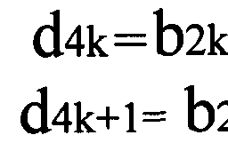
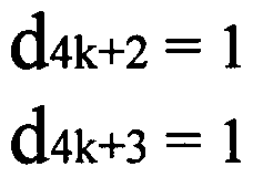
- Step S620 The four-part TFCI information is extended according to Equation 1, and each part of the TFCI information with a data length of 2 bits is converted into TFCI information with a data length of 4 bits. k+l [1]
- b2k and b2k+l represent the first and second binary codes in each part of the TFCI information before the expansion, respectively, d4k, d4k+l, d4k+2 and d4k+3 respectively represent the extended 4bits of each group.
- the first, second, third, and fourth binary codes in the TFCI information are the first, second, third, and fourth binary codes in the TFCI information.
- Step S630 modulating the expanded first, second, third, and fourth partial TFCI information respectively, that is, mapping the four-part TFCI information to the four maximum power points in the LCR TDD 16QAM constellation without offset. .
- the modulation apparatus after modulating the expanded four-part TFCI information, respectively places them in corresponding positions in the data frame to encapsulate the data frame.
- the first part and the second part of the TFCI information are respectively placed on both sides of the Midamble code in the first time slot, that is, the first part of the data in the first time slot.
- the front end and the front end of the second partial data; for the same reason, the third partial and fourth partial TFCI information are respectively placed on both sides of the Midamble code in the second time slot.
- the four-part TFCI information may also be placed at other locations in each time slot, for example, the front end of the first portion of data and the end of the second portion of data, which are not described herein.
- the modulation device After the modulation device encapsulates the data frame, it can send it to the corresponding receiver.
- the modulation device when the LCR TDD MBMS service uses a Transmission Time Interva (TTI) with a duration greater than 10 ms, for example, 20 ms, 40 ms, or 80 ms, the modulation device repeatedly transmits the 10 ms data frame in a period of 10 ms. .
- TTI Transmission Time Interva
- the demodulation performance of the TFCI information can be ensured to the greatest extent, and at the same time, since the four maximum power points have the same power, thus, the modulation Power fluctuations do not occur in the system during the process.
- the modulation device only needs to map the extended partial TFCI information to the same maximum power point "1111” for modulation, or respectively to the two maximum power points"
- the same technical effect can be achieved by modulating 0011" and "1111".
- the modulating device may alternately modulate the same TFCI information between the maximum power point and the minimum power point.
- the expansion unit 51 in the modulating device further includes a second determining unit 512 and a second processing unit 513.
- the second determining unit 512 is configured to determine a minimum power point in the LCR TDD 16QAM constellation
- the second processing unit 513 is configured to expand the divided partial TFCI information to correspond to the identifier of the minimum power point;
- the modulating device alternately uses the first processing unit 511 and the second processing unit 513 to expand the TFCI information after the equalization according to a preset period, that is, in a preset period of the TTI.
- the TFCI information is extended, and, in one of any two adjacent cycles, the equalized partial TFCI information is extended to correspond to the identification of the maximum power point, and in another cycle, the equalization is performed.
- Each part of the TFCI information is extended to correspond to the identification of the minimum power point.
- the modulating unit 52 is configured to map the extended partial TFCI information to a corresponding maximum power point or a minimum power point.
- one TTI includes 20 ms
- a data frame is transmitted for 10 ms
- the modulation device needs to modulate the TFCI information twice before encapsulating the A data frame and the B data frame.
- FIG. 7B in this embodiment, the detailed process of the second method for modulating the TFCI information by the modulating device according to the LCR TDD 16QAM constellation diagram as follows:
- Step S700 The modulation device acquires the original TFCI information that needs to be modulated in the UI.
- the original TFCI information is "00011011".
- Step S710 The modulation device divides the original TFCI information into four parts in units of 2 bits, and the four parts of the TFCI information are "00", "01", “10", and "11", respectively.
- Step S720 The modulation device expands “00”, “01”, “10”, and “11” according to Formula 1, respectively, and converts them into “0011”, “0111”, “1011”, and “1111", so that Corresponding to the identification of the four maximum power points in the LCR TDD 16QAM constellation.
- Step S730 The modulating device respectively modulates the first, second, third and fourth partial TFCI information extended according to the formula 1, as shown in FIG. 4, that is, "0011", “0111”, “1011” and “1111” is mapped to the four maximum power points in the LCR TDD 16QAM constellation without offset, respectively.
- the modulating device After modulating the expanded first, second, third, and fourth portions of TFCI information, the modulating device encapsulates the TFCI information in a corresponding position in the A data frame.
- Step S740 The modulation device expands “00”, “01”, “10”, and “11” according to Formula 2, and converts them into “0000”, “0100”, “1000”, and “1100", so that Corresponding to the identification of the four minimum power points in the LCR TDD 16QAM constellation.
- Equation 2 when the modulation device expands the above four-part TFCI information according to Formula 2, two binary codes are added at the end of each group of TFCI information. 00".
- Step S750 The modulating device respectively modulates the first, second, third and fourth partial TFCI information extended according to the formula 2, as shown in FIG. 7C, that is, "0000", “0100", “1000” and “1100” is mapped to the four minimum powers in the LCR TDD 16QAM constellation without offset, respectively Point.
- the modulating device After modulating the expanded first, second, third, and fourth portions of TFCI information, the modulating device encapsulates the TFCI information in a corresponding position in the B data frame.
- the modulating device After the B-packet completes the B data frame, the modulating device further expands each part of the TFCI information that is evenly separated from the original TFCI information according to Equation 1, and maps the expanded TFCI information to the LCR TDD 16QAM constellation map.
- the modulated partial TFCI information is encapsulated in corresponding positions in the C data frame; for the same reason, after the C data frame is encapsulated, the modulation device again according to formula 2
- Each part of the TFCI information is extended in the TFCI information, and the extended part of the TFCI information is respectively mapped to the four minimum power points according to the LCR TDD 16QAM constellation, and then encapsulated in the D data frame respectively. The corresponding location.
- the modulation device when a TTI in the system contains a duration greater than 10 ms, for example, 20 ms, 40 ms, or 80 ms, the modulation device alternately uses the maximum power point and the minimum power point pair to be separated from the original TFCI information.
- Each part of the TFCI information is modulated, thus not only ensuring the demodulation performance of the TFCI information, but also equalizing the average power in the system, and also avoiding the phenomenon that the average power is high in the system, thereby further improving the stability of the system. .
- the modulation apparatus in order to balance the demodulation performance of the TFCI information and the peak-to-average ratio in the system, modulates each part of the TFCI information that is divided from the original TFCI information. It can be mapped to an intermediate power point in the LCR TDD 16QAM constellation for modulation.
- the extension unit 51 in the modulation apparatus includes a third determination unit 514 and a third processing unit 515.
- the third determining unit 514 is configured to determine that the specified energy point is an LCR TDD 16QAM constellation An intermediate power point in the figure, wherein the intermediate power point is an energy point that is not attributed to a maximum power point and a minimum power point in the constellation diagram;
- the third processing unit 515 is configured to extend the equalized partial TFCI information to correspond to an identifier of an intermediate power point in the LCR TDD 16QAM constellation;
- the modulating unit 52 is further configured to map the expanded partial TFCI information to the corresponding intermediate power point.
- each energy point is uniformly distributed and the distance between any two adjacent energy points is equal, it can be seen that it is located in each quadrant and The eight intermediate power points identified as "0001", “0110”, “1010”, “1101”, “1001”, “0010", “1110”, and “0101" are equal to the origin, then mapped to The signal power of the TFCI information of the eight energy points is also equal.
- the distance from the intermediate power point to the origin is greater than the distance from the minimum power point to the origin, and is smaller than the distance from the maximum power point to the origin.
- the signal strength of the TFCI information can be guaranteed to a certain extent, and the average power in the system is neither too high nor too low, so that the demodulation performance of the TFCI information and the system can be balanced. Peak to average ratio.
- the original TFCI information in the TTI is "00011011", and the modulation device is divided into four parts in units of 2 bits, which are respectively "00", "01", “10", and "11", and the modulation device
- the modulation device When the four parts of TFCI information are modulated, they may be mapped to any four intermediate power points in the LCR TDD 16QAM constellation after expansion; wherein a preferred modulation method is to extend the four-part TFCI.
- the information is mapped to intermediate power points located in different quadrants, respectively.
- the detailed process of the third method for modulating the TFCI information by the modulation device is as follows:
- Step S900 The modulation device acquires the original TFCI information "00011011” in the TTI, and divides it into “00", “01”, “10”, and “11” in units of 2 bits.
- Step S910 The modulation device expands “00”, “01”, “10”, and “11” according to Formula 3, and converts it to "0001", “0110", “1010”, and “1101", respectively Corresponds to the identification of the four intermediate power points shown in FIG. 8B.
- the modulation device expands "00", “01”, “10”, and “11” according to Equation 4, converting it to "0010", “0101”, “1001”, and “1110", respectively, and Fig. 8C The identification of the four intermediate power points shown corresponds.
- Step S920 The modulation device modulates the expanded portions of the TFCI information, that is, "0001", “0110”, “1010”, and “1101” are respectively offset without offset Map to four intermediate power points in the LCR TDD 16QAM constellation as shown in Figure 8B; or, map "0010", “0101”, “1001”, and “1110” to offset as shown in Figure 8C, respectively.
- the modulating device can alternately use the formula 3 and the formula 4 for the data frame in the ⁇ to divide the four from the original TFCI information.
- the partial TFCI information is spread and alternately modulated according to the LCR TDD 16QAM constellation as shown in Fig. 8B and the LCR TDD 16QAM constellation as shown in Fig. 8C. In this way, a balance can be achieved between maintaining the demodulation performance of the TFCI information and the peak-to-average ratio in the equalization system, and alternately using the above two methods to modulate the extended TFCI information also brings a certain degree to the system.
- the energy point labeled "1001" is far away from the interference to a certain extent, so that the ideal modulation result is obtained, so that the demodulation performance of the modulated TFCI information can be ensured, thereby greatly reducing the probability of occurrence of the mediation error, and further Bring a certain diversity gain to the system.
- the modulating device may map the extended partial TFCI information to the same intermediate power point "1110" for modulation, or respectively map to two intermediate power points "1110" and “1101". "The same technical effect can be achieved by performing the modulation. This embodiment only provides a preferred embodiment, and details are not described herein again.
- the modulation apparatus may also use the method provided in the embodiment of the present invention to The TFCI information is modulated.
- the data length of the TFCI information is still 8 bits
- the modulating device can also divide the acquired original TFCI information into four parts, and respectively at the last position of the four-part TFCI information. 4 bits are added to expand the data length of the four-part TFCI information from 2 bits to 6 bits, that is, the data length of the original TFCI information is extended from 8 bits to 24 bits, and then the modulation device maps the expanded TFCI information without offset. At least one energy point other than the minimum power point in the LCRTDD 64QAM constellation for modulation.
- the modulation device only needs to equally divide the TFCI information in units of 2 bits, that is, each method can be used to Part of the TFCI information is extended, and the extended partial TFCI information is modulated according to the LCR TDD 64QAM constellation.
- the LCR TDD MBMS adopts the 256QAM modulation scheme
- the TFCI information in the system can also be modulated by using various methods provided by the present invention, and details are not described herein again.
- the modulation device will be expanded in addition to the method shown in FIG. 6B.
- the TFCI information is encapsulated on both sides of the Midamble code, and the extended TFCI information can also be encapsulated on both sides of the data portion in the data frame.
- the modulation device acquires 16 bits of original TFCI information, divides it into eight parts and expands it in units of 2 bits, and then transmits the extension.
- the eight-part TFCI information needs to occupy two data frames with a duration of 10 ms.
- Each data frame still contains two time slots with a duration of 5 ms. In each time slot, each of the two extended partial TFCI information is placed separately.
- the Preamble code and at the end of the data portion that is, on both sides of the data portion.
- the modulation apparatus when the modulation apparatus modulates the acquired original TFCI information, the TFCI information that is separated from the original TFCI information is expanded according to the identifier of the energy point specified in the preset constellation diagram. And mapping the extended TFCI information to the corresponding energy point without offset, so that the signal strength of the TFCI information in the system can be ensured, thereby ensuring the demodulation performance of the TFCI information, and at the same time, avoiding The average power fluctuation is caused in the system, which improves the stability of the system to some extent.
Landscapes
- Engineering & Computer Science (AREA)
- Computer Networks & Wireless Communication (AREA)
- Signal Processing (AREA)
- Quality & Reliability (AREA)
- Digital Transmission Methods That Use Modulated Carrier Waves (AREA)
- Time-Division Multiplex Systems (AREA)
Description


Claims
Priority Applications (4)
| Application Number | Priority Date | Filing Date | Title |
|---|---|---|---|
| JP2010520404A JP4980467B2 (ja) | 2007-08-13 | 2008-08-13 | Tfci情報の変調方法及び装置 |
| US12/673,490 US8611461B2 (en) | 2007-08-13 | 2008-08-13 | Method and device for modulating the information of TFCI |
| EP08783645.8A EP2180650B1 (en) | 2007-08-13 | 2008-08-13 | A method and device for modulating the information of tfci |
| KR1020107005494A KR101166539B1 (ko) | 2007-08-13 | 2008-08-13 | 티에프씨아이 정보의 변조 방법 및 장치 |
Applications Claiming Priority (2)
| Application Number | Priority Date | Filing Date | Title |
|---|---|---|---|
| CN2007101202087A CN101370160B (zh) | 2007-08-13 | 2007-08-13 | 一种tfci信息的调制方法及装置 |
| CN200710120208.7 | 2007-08-13 |
Publications (1)
| Publication Number | Publication Date |
|---|---|
| WO2009021407A1 true WO2009021407A1 (en) | 2009-02-19 |
Family
ID=40350365
Family Applications (1)
| Application Number | Title | Priority Date | Filing Date |
|---|---|---|---|
| PCT/CN2008/001463 Ceased WO2009021407A1 (en) | 2007-08-13 | 2008-08-13 | A method and device for modulating the information of tfci |
Country Status (6)
| Country | Link |
|---|---|
| US (1) | US8611461B2 (zh) |
| EP (1) | EP2180650B1 (zh) |
| JP (1) | JP4980467B2 (zh) |
| KR (1) | KR101166539B1 (zh) |
| CN (1) | CN101370160B (zh) |
| WO (1) | WO2009021407A1 (zh) |
Families Citing this family (1)
| Publication number | Priority date | Publication date | Assignee | Title |
|---|---|---|---|---|
| CN104641574B (zh) * | 2012-09-19 | 2018-06-15 | 诺基亚通信公司 | 用于无线通信的方法和装置、以及计算机可读介质 |
Citations (4)
| Publication number | Priority date | Publication date | Assignee | Title |
|---|---|---|---|---|
| CN1372394A (zh) * | 2001-02-27 | 2002-10-02 | 西门子公司 | 经无线信道传输比特序列的方法 |
| CN1418421A (zh) * | 2001-01-16 | 2003-05-14 | 皇家菲利浦电子有限公司 | 比特交织的编码调制映射 |
| CN1481629A (zh) * | 2000-12-21 | 2004-03-10 | ���˹���Ѷ��� | 编码的正交调幅 |
| WO2006089569A1 (en) * | 2005-02-28 | 2006-08-31 | Ntt Docomo, Inc. | Method and apparatus for transmitting and receiving bit interleaved coded modulation signal |
Family Cites Families (8)
| Publication number | Priority date | Publication date | Assignee | Title |
|---|---|---|---|---|
| US5105442A (en) * | 1990-11-07 | 1992-04-14 | At&T Bell Laboratories | Coded modulation with unequal error protection |
| US5237292A (en) * | 1992-07-01 | 1993-08-17 | Space Systems/Loral | Quadrature amplitude modulation system with compensation for transmission system characteristics |
| US5815531A (en) * | 1996-06-12 | 1998-09-29 | Ericsson Inc. | Transmitter for encoded data bits |
| US5966412A (en) * | 1997-06-30 | 1999-10-12 | Thomson Consumer Electronics, Inc. | Apparatus and method for processing a Quadrature Amplitude Modulated (QAM) signal |
| US7254180B1 (en) * | 1999-06-01 | 2007-08-07 | International Business Machines Corporation | Discrete multitone transmission systems |
| KR100421164B1 (ko) * | 2000-06-12 | 2004-03-04 | 삼성전자주식회사 | 이동통신시스템에서 전송율 정보 부호화 및 복호화 장치 및 방법 |
| KR100480775B1 (ko) * | 2000-11-18 | 2005-04-06 | 삼성전자주식회사 | 다중파 전송 시스템을 위한 최고 대 평균비 감소 방법 및장치 |
| WO2002065724A1 (en) * | 2001-02-13 | 2002-08-22 | Mitsubishi Denki Kabushiki Kaisha | Multiple-level modulating method, multiple-level demodulating method, and multiple-level modulating/demodulating method |
-
2007
- 2007-08-13 CN CN2007101202087A patent/CN101370160B/zh not_active Expired - Fee Related
-
2008
- 2008-08-13 WO PCT/CN2008/001463 patent/WO2009021407A1/zh not_active Ceased
- 2008-08-13 EP EP08783645.8A patent/EP2180650B1/en not_active Not-in-force
- 2008-08-13 JP JP2010520404A patent/JP4980467B2/ja not_active Expired - Fee Related
- 2008-08-13 US US12/673,490 patent/US8611461B2/en not_active Expired - Fee Related
- 2008-08-13 KR KR1020107005494A patent/KR101166539B1/ko not_active Expired - Fee Related
Patent Citations (4)
| Publication number | Priority date | Publication date | Assignee | Title |
|---|---|---|---|---|
| CN1481629A (zh) * | 2000-12-21 | 2004-03-10 | ���˹���Ѷ��� | 编码的正交调幅 |
| CN1418421A (zh) * | 2001-01-16 | 2003-05-14 | 皇家菲利浦电子有限公司 | 比特交织的编码调制映射 |
| CN1372394A (zh) * | 2001-02-27 | 2002-10-02 | 西门子公司 | 经无线信道传输比特序列的方法 |
| WO2006089569A1 (en) * | 2005-02-28 | 2006-08-31 | Ntt Docomo, Inc. | Method and apparatus for transmitting and receiving bit interleaved coded modulation signal |
Also Published As
| Publication number | Publication date |
|---|---|
| KR20100049647A (ko) | 2010-05-12 |
| KR101166539B1 (ko) | 2012-07-19 |
| EP2180650A4 (en) | 2013-03-20 |
| US8611461B2 (en) | 2013-12-17 |
| EP2180650B1 (en) | 2013-10-30 |
| CN101370160B (zh) | 2011-12-21 |
| JP4980467B2 (ja) | 2012-07-18 |
| JP2010536281A (ja) | 2010-11-25 |
| EP2180650A1 (en) | 2010-04-28 |
| CN101370160A (zh) | 2009-02-18 |
| US20110280339A1 (en) | 2011-11-17 |
Similar Documents
| Publication | Publication Date | Title |
|---|---|---|
| KR101783926B1 (ko) | Wlαn을 위한 스트림 개수 지시자 | |
| JP6552128B2 (ja) | 複素次元あたりの投影が少ないコードブックを生成するためのシステムおよび方法ならびにその利用 | |
| JP4284774B2 (ja) | 送信装置、受信装置、通信システム、送信方法及び通信方法 | |
| CN110169025B (zh) | 发送装置、接收装置、发送方法及接收方法 | |
| CN101933272B (zh) | 用于简化redhot a和b无线发射/接收单元的上行链路状态标志(usf)的解码复杂度的方法 | |
| CN102763358B (zh) | 发送装置、接收装置、通信系统以及通信方法 | |
| US10136287B2 (en) | Method and apparatus for close proximity communications | |
| CN108882366B (zh) | 一种下行控制信息dci的传输方法及装置 | |
| CN101267418B (zh) | 发送、接收通信系统参数的方法、装置及其系统 | |
| CN101330307B (zh) | 秩指示信息的发送方法及装置、接收方法及装置 | |
| EP3447957B1 (en) | Method and device for feeding back channel state information | |
| CN113411162B (zh) | 数据传输方法、设备及系统 | |
| WO2013079034A1 (zh) | 下行数据发送、接收方法及基站与用户终端 | |
| WO2018100428A1 (en) | Method and device for signal processing in communication system | |
| CN104868982A (zh) | 基带主处理单元、数字前端、基带单元及数据传输方法 | |
| WO2009021407A1 (en) | A method and device for modulating the information of tfci | |
| KR102309057B1 (ko) | 시그널링 필드를 이용하는 무선 통신 방법 및 무선 통신 단말 | |
| CN112005591A (zh) | 多种接入资源的信令 | |
| CN118104205A (zh) | 基于脉冲整形的参考信号 | |
| CN102957518A (zh) | 一种应答信息的发送方法、接收方法和用户设备及基站 |
Legal Events
| Date | Code | Title | Description |
|---|---|---|---|
| 121 | Ep: the epo has been informed by wipo that ep was designated in this application |
Ref document number: 08783645 Country of ref document: EP Kind code of ref document: A1 |
|
| WWE | Wipo information: entry into national phase |
Ref document number: 278/MUMNP/2010 Country of ref document: IN |
|
| WWE | Wipo information: entry into national phase |
Ref document number: 2010520404 Country of ref document: JP |
|
| NENP | Non-entry into the national phase |
Ref country code: DE |
|
| WWE | Wipo information: entry into national phase |
Ref document number: 2008783645 Country of ref document: EP |
|
| WWE | Wipo information: entry into national phase |
Ref document number: 12673490 Country of ref document: US |
|
| ENP | Entry into the national phase |
Ref document number: 20107005494 Country of ref document: KR Kind code of ref document: A |