WO2009048291A1 - Enhanced sound source localization system and method by using a movable microphone array - Google Patents
Enhanced sound source localization system and method by using a movable microphone array Download PDFInfo
- Publication number
- WO2009048291A1 WO2009048291A1 PCT/KR2008/005969 KR2008005969W WO2009048291A1 WO 2009048291 A1 WO2009048291 A1 WO 2009048291A1 KR 2008005969 W KR2008005969 W KR 2008005969W WO 2009048291 A1 WO2009048291 A1 WO 2009048291A1
- Authority
- WO
- WIPO (PCT)
- Prior art keywords
- cross spectrum
- sound source
- analyzer
- spectrum matrix
- sensors
- Prior art date
- Legal status (The legal status is an assumption and is not a legal conclusion. Google has not performed a legal analysis and makes no representation as to the accuracy of the status listed.)
- Ceased
Links
Classifications
-
- G—PHYSICS
- G10—MUSICAL INSTRUMENTS; ACOUSTICS
- G10L—SPEECH ANALYSIS TECHNIQUES OR SPEECH SYNTHESIS; SPEECH RECOGNITION; SPEECH OR VOICE PROCESSING TECHNIQUES; SPEECH OR AUDIO CODING OR DECODING
- G10L21/00—Speech or voice signal processing techniques to produce another audible or non-audible signal, e.g. visual or tactile, in order to modify its quality or its intelligibility
- G10L21/02—Speech enhancement, e.g. noise reduction or echo cancellation
-
- G—PHYSICS
- G10—MUSICAL INSTRUMENTS; ACOUSTICS
- G10L—SPEECH ANALYSIS TECHNIQUES OR SPEECH SYNTHESIS; SPEECH RECOGNITION; SPEECH OR VOICE PROCESSING TECHNIQUES; SPEECH OR AUDIO CODING OR DECODING
- G10L15/00—Speech recognition
- G10L15/20—Speech recognition techniques specially adapted for robustness in adverse environments, e.g. in noise, of stress induced speech
-
- G—PHYSICS
- G01—MEASURING; TESTING
- G01S—RADIO DIRECTION-FINDING; RADIO NAVIGATION; DETERMINING DISTANCE OR VELOCITY BY USE OF RADIO WAVES; LOCATING OR PRESENCE-DETECTING BY USE OF THE REFLECTION OR RERADIATION OF RADIO WAVES; ANALOGOUS ARRANGEMENTS USING OTHER WAVES
- G01S3/00—Direction-finders for determining the direction from which infrasonic, sonic, ultrasonic or electromagnetic waves, or particle emission, not having a directional significance, are being received
- G01S3/80—Direction-finders for determining the direction from which infrasonic, sonic, ultrasonic or electromagnetic waves, or particle emission, not having a directional significance, are being received using ultrasonic, sonic or infrasonic waves
- G01S3/802—Systems for determining direction or deviation from predetermined direction
- G01S3/809—Rotating or oscillating beam systems using continuous analysis of received signal for determining direction in the plane of rotation or oscillation or for determining deviation from a predetermined direction in such a plane
-
- G—PHYSICS
- G10—MUSICAL INSTRUMENTS; ACOUSTICS
- G10L—SPEECH ANALYSIS TECHNIQUES OR SPEECH SYNTHESIS; SPEECH RECOGNITION; SPEECH OR VOICE PROCESSING TECHNIQUES; SPEECH OR AUDIO CODING OR DECODING
- G10L15/00—Speech recognition
- G10L15/08—Speech classification or search
- G10L15/10—Speech classification or search using distance or distortion measures between unknown speech and reference templates
-
- G—PHYSICS
- G10—MUSICAL INSTRUMENTS; ACOUSTICS
- G10L—SPEECH ANALYSIS TECHNIQUES OR SPEECH SYNTHESIS; SPEECH RECOGNITION; SPEECH OR VOICE PROCESSING TECHNIQUES; SPEECH OR AUDIO CODING OR DECODING
- G10L19/00—Speech or audio signals analysis-synthesis techniques for redundancy reduction, e.g. in vocoders; Coding or decoding of speech or audio signals, using source filter models or psychoacoustic analysis
- G10L19/02—Speech or audio signals analysis-synthesis techniques for redundancy reduction, e.g. in vocoders; Coding or decoding of speech or audio signals, using source filter models or psychoacoustic analysis using spectral analysis, e.g. transform vocoders or subband vocoders
-
- G—PHYSICS
- G10—MUSICAL INSTRUMENTS; ACOUSTICS
- G10L—SPEECH ANALYSIS TECHNIQUES OR SPEECH SYNTHESIS; SPEECH RECOGNITION; SPEECH OR VOICE PROCESSING TECHNIQUES; SPEECH OR AUDIO CODING OR DECODING
- G10L21/00—Speech or voice signal processing techniques to produce another audible or non-audible signal, e.g. visual or tactile, in order to modify its quality or its intelligibility
- G10L21/02—Speech enhancement, e.g. noise reduction or echo cancellation
- G10L21/0208—Noise filtering
- G10L21/0216—Noise filtering characterised by the method used for estimating noise
-
- H—ELECTRICITY
- H04—ELECTRIC COMMUNICATION TECHNIQUE
- H04R—LOUDSPEAKERS, MICROPHONES, GRAMOPHONE PICK-UPS OR LIKE ACOUSTIC ELECTROMECHANICAL TRANSDUCERS; ELECTRIC HEARING AIDS; PUBLIC ADDRESS SYSTEMS
- H04R3/00—Circuits for transducers
- H04R3/005—Circuits for transducers for combining the signals of two or more microphones
-
- G—PHYSICS
- G10—MUSICAL INSTRUMENTS; ACOUSTICS
- G10L—SPEECH ANALYSIS TECHNIQUES OR SPEECH SYNTHESIS; SPEECH RECOGNITION; SPEECH OR VOICE PROCESSING TECHNIQUES; SPEECH OR AUDIO CODING OR DECODING
- G10L21/00—Speech or voice signal processing techniques to produce another audible or non-audible signal, e.g. visual or tactile, in order to modify its quality or its intelligibility
- G10L21/02—Speech enhancement, e.g. noise reduction or echo cancellation
- G10L21/0208—Noise filtering
- G10L21/0216—Noise filtering characterised by the method used for estimating noise
- G10L2021/02161—Number of inputs available containing the signal or the noise to be suppressed
- G10L2021/02166—Microphone arrays; Beamforming
Definitions
- the present invention relates to an enhanced sound source localization system and method by using a movable microphone array.
- Sound characteristics of various products such as automobiles and electric home appliances, are recognized as main performance indicators. From this reason, efforts for more quiet products continuously made from the beginning of their development stage.
- a method is generally used as follow. In first, it is found where sound is generated from and what cause of that sound. And then, through the design change of product, low noise product can be developed. To this end, a measuring method for localizing a sound source is primarily required.
- a sound intensity measuring method using an intensity probe and the other is a sound source localization method using a microphone array beamforming method. Fig.
- FIG. 1 illustrates examples of a microphone array measuring method applied to various types of research and development.
- the microphone array method which has recently been developed, several microphones are used for measuring sensors, and the power distribution of a sound source in a space is calculated through the signal processing using a phase difference of measured signal based on distances between a sound source and the measuring sensors. Then, from the distribution map, the location of maximum strength of power can be accepted as a sound source location.
- the measurement accuracy depends on the number of sensors in used. It is known that larger number of sensors give more accurate results .
- a steering vector which can be defined differently depending on wave propagation characteristics is used to apply the microphone array beamforming method.
- the steering vector IS calculated from positions of a sound source and measuring sensors .
- the steering vector between m-th sound source and n-th measuring sensor is defined by the following Equation 2.
- the matrix having steering vectors of all the sensors from the m-th sound source, calculated as described above, is designated by a steering vector matrix
- the beam power map that means the intensity distribution of a sound source in a space can be evaluated as follows.
- a beam power b m at the m-th sound source can be calculated by the following Equation 3.
- m order to calculate the beam power map a grid of virtual sound source is determined at an expected location of that sound source, and beam powers at each grid point are calculated Then, the calculated beam powers are shown in a space, thereby obtaining a beam power map.
- the measurement accuracy m a microphone array measuring system is depending on the number and relative location of sensors m used. It can be quantitatively evaluated by a beam width and a side- lobe rejection, which are defined as follows.
- a beam power map can be obtained by the arrangement of microphones used in measurement as shown m Fig. 2.
- a beam width is defined by a width of a beam in the space at a point corresponding to a level of -3dB from a main lobe corresponding to the position of the sound source.
- a side- lobe rejection is defined by a level difference between side and main lobes, shown in a position at which the sound source does not exist.
- Fig. 2 illustrates an accuracy difference m a microphone array measuring system depending on the number of sensors used. 31 sensors are used in Fig. 2 (a) , and 121 sensors are used m Fig. 2 (b) . As shown in Fig. 2, it can be seen that the performance is improved as the number of sensors used is increased.
- An object of the present invention is to provide an enhanced sound source localization system and method by using a movable microphone array, wherein a sound source is measured by moving a limited number of microphones, and a signal processing method capable of synchronizing the microphones, so that measurement accuracy can be improved. More specifically, the present invention provides an enhanced sound source localization system and method by using a movable microphone array, wherein one fixed sensor is used, and sound data is obtained at a larger number of measuring points by allowing the other sensors to be moved, so that independently measured signals can be corrected as simultaneously measured signals by applying a synchronizing method using a signal of the fixed sensor.
- an enhanced sound source localization system by using a microphone array beamforming method, which includes: a fixed sensor measuring a sound at a fixed point; a plurality of movable sensors spaced apart from the fixed sensor at a predetermined distance to measure the sound at a plurality of measuring points while moving along a predetermined path about the fixed sensor; and an analyzer receiving sound data measured from the fixed sensor and the movable sensors to perform data analysis, wherein a measured result is obtained by synchronizing the sound data measured from the plurality of movable sensors with the sound data measured from the fixed sensor .
- an enhanced sound source localization method by using the aforementioned sound source localization system, which includes the steps of: a) the analyzer obtaining an ensemble averaged cross spectrum matrix by using sound data measured from the one fixed sensor and the plurality of movable sensors; b) the analyzer repeating a predetermined times (K " ) an operation of moving the movable sensors to new positions, re-measuring sound data and obtaining an ensemble averaged cross spectrum matrix ( ⁇ A i,j,k >) using the sound data; c) the analyzer correcting a difference of phases in the ensemble averaged cross spectrum matrix ( ⁇ A i,j,k >) , thereby obtaining a synchronized cross spectrum matrix ( ⁇ A' i,j,k >) ; d) the analyzer rearranging the synchronized cross spectrum matrix ( ⁇ A' i,j,k >) as a cross spectrum matrix ( ⁇ A" a,b >) at independent positions; e) the analyzer obtaining unknown
- the analyzer may obtain the synchronized cross spectrum matrix by using the following equation;
- i and j denote sensor numbers and are variables each having an integer between 1 to N when assuming that the total number of the fixed sensor and the plurality of movable sensors is N 1 and k denotes a measuring time and is a variable having an integer between 1 to K.
- the analyzer may obtain the unknown terms m the cross spectrum matrix ( ⁇ A" a,b >) at independent positions by using the following equation;
- the analyzer may obtain the synchronized beam power ⁇ b" m ) by using the following equation;
- measurement performance is determined by the number of high-priced measuring sensors, i.e., microphones when a sound source is measured using the conventional microphone array beamformmg method, it is required to increase the number of measuring sensors for the purpose of high measurement performance.
- a sound source is measured by moving a limited number of microphones, so that measurement accuracy can be improved.
- a sound source cannot be measured by moving sensors.
- a sound source is measured by moving microphones, and a signal processing method capable of synchronizing the microphones is applied, thereby obtaining measurement results. Accordingly, the number of sensors required to evaluate measured values in a range of desired measurement accuracy can be considerably decreased, and therefore, measuring cost can be remarkably saved.
- Fig. 1 illustrates examples of a microphone array measuring method applied to various types of research and development ;
- Fig. 2 illustrates an accuracy difference in a microphone array measuring method depending on the number of sensors used
- Fig. 3 illustrates arrangements of sensors in verification through numerical simulation
- Fig. 4 illustrates comparison of beam power maps for respective measuring methods
- Fig. 5 illustrates comparison of performance characteristics m accordance with frequencies for the respective measuring methods.
- the conventional microphone array measuring method sound wave signals generated from an arbitrary sound source is measured using N microphones positioned at difference places, and an ensemble averaged cross spectrum matrix is obtained. Then, the measurement is repeated K times in the state that only one of sensors used is disposed at a fixed position, and the other sensors are moved to new positions.
- the fixed sensor is numbered by "1”
- the obtained cross spectrum is referred to as ⁇ A i,j,k >.
- the obtained cross spectrum refers to an ensemble averaged cross spectrum obtained in a k-th measurement with respect to an i- th and j-th sensor.
- ⁇ A 1,1,1 > and ⁇ A 1,1,k > denote auto spectra of the first microphone at first and k-th measurements, respectively.
- the ⁇ A' i,j,k > is a three -dimens ional matrix of a synchronized [NxNxK] and has data measured at different positions except the first microphone. Therefore, the ⁇ A' i,j,k > can be rearranged as a cross spectrum matrix at independent positions as expressed in Equation 5.
- the cross spectrum matrix becomes a two-dimensional matrix of [( [N-1) K+1) x ( (N-
- the same measurement accuracy as obtained using a plurality of high-priced sensors can be obtained only using a limited number of sensors.
- the performance of the measuring method of the present invention was compared with that of the conventional measuring method through simulation using a numerical method.
- Fig. 3 illustrates arrangements of sensors in verification through numerical simulation.
- Fig. 3 (a) illustrates an arrangement of 31 sensors for measuring using the conventional beamforming method as shown in Fig. 2 (a) .
- Fig. 3 (b) illustrates an arrangement of 121 sensors for measuring using the conventional beamforming method as shown m Fig. 2 (b) .
- Fig. 3 (c) illustrates an arrangement of movable 31 sensors for measuring using the measuring method of the present invention.
- Fig. 4 illustrates numerical simulation results of beam power maps for the respective measuring methods of Fig. 3. As shown m Fig. 4, it can be seen that side- lobe rejections are remarkably improved as the number of sensors used is increased. In the measuring method of the present invention, 31 microphones are substantially used. However, it can be seen that the measuring method of the present invention has a result almost similar to that when 121 sensors are used in the conventional measuring method.
- Fig. 5 illustrates graphs for comparison of performance characteristics in accordance with frequencies for the respective measuring methods, in which beam widths and side- lobe rejections are numerically compared for the purpose of numerical comparison of the aforementioned performance improvement .
- the measured result of the present invention has performance close to that using 121 sensors in the conventional measuring method, even though only 31 sensors are used in the measuring method of the present invention.
- the measuring method of the present invention using a movable microphone array When the measuring method of the present invention using a movable microphone array is applied, the same measurement accuracy as obtained using a plurality of sensors can be obtained only using a small number of sensors, and measurement can be performed at a low cost. Accordingly, it is expected that environmental sound can be reduced as application of a method for reducing sound is extended. Further, the measuring method of the present invention can be extended to various fields through modification of a steering vector in accordance with measurement conditions. Furthermore, the measuring method of the present invention can be applied to localization of a sound source transmitted in the water in addition to a sound source transmitted in the air.
Landscapes
- Engineering & Computer Science (AREA)
- Physics & Mathematics (AREA)
- Health & Medical Sciences (AREA)
- Acoustics & Sound (AREA)
- Computational Linguistics (AREA)
- Audiology, Speech & Language Pathology (AREA)
- Human Computer Interaction (AREA)
- Multimedia (AREA)
- Signal Processing (AREA)
- Quality & Reliability (AREA)
- General Physics & Mathematics (AREA)
- General Health & Medical Sciences (AREA)
- Otolaryngology (AREA)
- Remote Sensing (AREA)
- Radar, Positioning & Navigation (AREA)
- Spectroscopy & Molecular Physics (AREA)
- Measurement Of Velocity Or Position Using Acoustic Or Ultrasonic Waves (AREA)
- Circuit For Audible Band Transducer (AREA)
- Measurement Of Mechanical Vibrations Or Ultrasonic Waves (AREA)
Abstract
Disclosed is an enhanced sound source localization technique, which can overcome a limitation of a conventional beamformmg method using a fixed microphone array by applying a movable microphone array and an analytic algorithm related to the movable microphone array. An object of the present invention is to provide an enhanced sound source localization system and method by using a movable microphone array, wherein a sound source is measured by moving a limited number of microphones, and a signal processing method capable of synchronizing the microphones, so that measurement accuracy can be improved. According to the present invention, a sound source is measured by moving a limited number of microphones, the number of sensors required to evaluate measured values in a range of desired measurement accuracy can be considerably decreased, and therefore, measuring cost can be remarkably saved.
Description
[DESCRIPTION]
[invention Title]
ENHANCED SOUND SOURCE LOCALIZATION SYSTEM AND METHOD BY USING A MOVABLE MICROPHONE ARRAY
[Technical Field]
The present invention relates to an enhanced sound source localization system and method by using a movable microphone array. Sound characteristics of various products, such as automobiles and electric home appliances, are recognized as main performance indicators. From this reason, efforts for more quiet products continuously made from the beginning of their development stage. For the noise reduction of product, a method is generally used as follow. In first, it is found where sound is generated from and what cause of that sound. And then, through the design change of product, low noise product can be developed. To this end, a measuring method for localizing a sound source is primarily required. Currently, there are two available source localizing method, one is a sound intensity measuring method using an intensity probe and the other is a sound source localization method using a microphone array beamforming method. Fig. 1 illustrates examples of a microphone array measuring method
applied to various types of research and development. In the microphone array method which has recently been developed, several microphones are used for measuring sensors, and the power distribution of a sound source in a space is calculated through the signal processing using a phase difference of measured signal based on distances between a sound source and the measuring sensors. Then, from the distribution map, the location of maximum strength of power can be accepted as a sound source location. In this microphone array method, the measurement accuracy depends on the number of sensors in used. It is known that larger number of sensors give more accurate results .
[Background Art]
In a conventional microphone array beamforming method, the procedure of sound source localization is as follows.
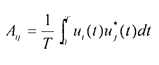
1) Sound waves u(t) generated from a sound source are measured using a plurality of microphones. Then, a cross spectrum matrix having cross spectra Aij between i-th and j-th microphones, defined by the following Equation 1, is calculated using a frequency analysis. At this time, an ensemble average is taken to improve measurement accuracy. The ensemble averaged cross spectrum matrix is referred to as
2) A steering vector which can be defined differently depending on wave propagation characteristics is used to apply the microphone array beamforming method. The steering vector IS calculated from positions of a sound source and measuring sensors . In the case of sound source which has square wave propagation characteristics, the steering vector between m-th sound source and n-th measuring sensor is defined by the following Equation 2. The matrix having steering vectors of all the sensors from the m-th sound source, calculated as described above, is designated by a steering vector matrix


Where, denotes a distance
 from the m-th sound source to the n-th sound source.
3) Using the cross spectra and steering vector matrix obtained through measurement, the beam power map that means the intensity distribution of a sound source in a space can be evaluated as follows. A beam power bm at the m-th sound source can be calculated by the following Equation 3.


The measurement accuracy m a microphone array measuring system is depending on the number and relative location of sensors m used. It can be quantitatively evaluated by a beam width and a side- lobe rejection, which are defined as follows. When a single sound source exists in a space, a beam power map can be obtained by the arrangement of microphones used in measurement as shown m Fig. 2. At this time, a beam width is defined by a width of a beam in the space at a point corresponding to a level of -3dB from a main lobe corresponding to the position of the sound source. A side- lobe rejection is defined by a level difference between side and main lobes, shown in a position at which the sound source does not exist. Therefore, accurate measurement system requires narrow beam width and high side- lobe rejection capability. Fig. 2 illustrates an accuracy difference m a microphone array measuring system depending on the number of sensors used. 31 sensors are used in Fig. 2 (a) , and 121 sensors are used m Fig. 2 (b) . As shown in Fig. 2, it can be
seen that the performance is improved as the number of sensors used is increased.
The reason why a large number of sensors are required in the conventional method is that if the numbers of signal measured at different position is increased, the noise signal is attenuated more by summing up the measured signals, and therefore, performance is improved. Sound signals at different location can be measured by moving microphone array with a small number of sensors. However, in the beamforming method, a beam power map requires simultaneously measured signals form all the sensors being used. This is because a phase difference between the respective measured signals, i.e., a difference of times at which a sound signal reaches the respective sensors, is applied to the beamforming method. Accordingly, in a measuring method using the conventional beamforming method, only the number of sensors is increased to improve its performance. Since the price of measuring sensors and data obtaining devices is very high, there is limitation in increasing the number of sensors. Therefore, it has been continuously required by those skilled in the art to develop a measuring method capable of improving measuring performance and saving costs .
[Disclosure]
[Technical Problem]
An object of the present invention is to provide an enhanced sound source localization system and method by using a movable microphone array, wherein a sound source is measured by moving a limited number of microphones, and a signal processing method capable of synchronizing the microphones, so that measurement accuracy can be improved. More specifically, the present invention provides an enhanced sound source localization system and method by using a movable microphone array, wherein one fixed sensor is used, and sound data is obtained at a larger number of measuring points by allowing the other sensors to be moved, so that independently measured signals can be corrected as simultaneously measured signals by applying a synchronizing method using a signal of the fixed sensor.
[Technical Solution]
According to an aspect of the present invention, there is provided an enhanced sound source localization system by using a microphone array beamforming method, which includes: a fixed sensor measuring a sound at a fixed point; a plurality of movable sensors spaced apart from the fixed sensor at a predetermined distance to measure the sound at a plurality of measuring points while moving along a predetermined path about
the fixed sensor; and an analyzer receiving sound data measured from the fixed sensor and the movable sensors to perform data analysis, wherein a measured result is obtained by synchronizing the sound data measured from the plurality of movable sensors with the sound data measured from the fixed sensor .
According to another aspect of the present invention, there is provided an enhanced sound source localization method by using the aforementioned sound source localization system, which includes the steps of: a) the analyzer obtaining an ensemble averaged cross spectrum matrix by using sound data measured from the one fixed sensor and the plurality of movable sensors; b) the analyzer repeating a predetermined times (K") an operation of moving the movable sensors to new positions, re-measuring sound data and obtaining an ensemble averaged cross spectrum matrix (<A i,j,k>) using the sound data; c) the analyzer correcting a difference of phases in the ensemble averaged cross spectrum matrix (<A i,j,k>) , thereby obtaining a synchronized cross spectrum matrix (<A'i,j,k>) ; d) the analyzer rearranging the synchronized cross spectrum matrix (<A'i,j,k>) as a cross spectrum matrix (<A"a,b>) at independent positions; e) the analyzer obtaining unknown terms in the cross spectrum matrix {<A"a,b>) at independent positions by using characteristics of the cross spectrum matrix; and f)
the analyzer obtaining a synchronized beam power (b"m) by using the cross spectrum matrix (<A"a,b>) at independent positions and a synchronized steering vector matrix

In the step c) , the analyzer may obtain the synchronized cross spectrum matrix by using the following equation;

Here, i and j denote sensor numbers and are variables each having an integer between 1 to N when assuming that the total number of the fixed sensor and the plurality of movable sensors is N1 and k denotes a measuring time and is a variable having an integer between 1 to K.
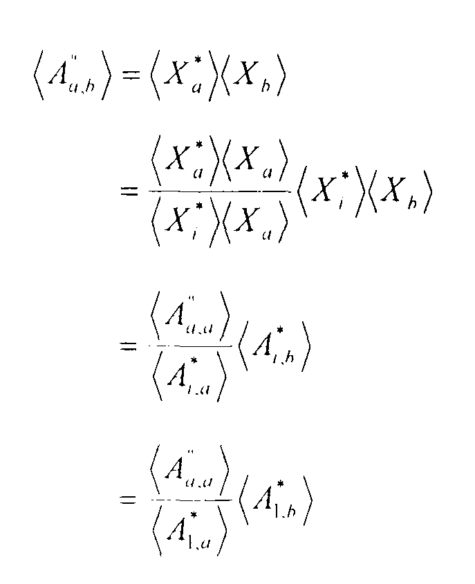
In the step e) , the analyzer may obtain the unknown terms m the cross spectrum matrix (<A"a,b>) at independent positions by using the following equation;
In the step f ) , the analyzer may obtain the synchronized
beam power {b"m) by using the following equation;

[Advantageous Effects]
Since measurement performance is determined by the number of high-priced measuring sensors, i.e., microphones when a sound source is measured using the conventional microphone array beamformmg method, it is required to increase the number of measuring sensors for the purpose of high measurement performance. However, in the present invention, a sound source is measured by moving a limited number of microphones, so that measurement accuracy can be improved. Particularly, since measurements are simultaneously performed in the conventional microphone array beamforming method, a sound source cannot be measured by moving sensors. However, in the present invention, a sound source is measured by moving microphones, and a signal processing method capable of synchronizing the microphones is applied, thereby obtaining measurement results. Accordingly, the number of sensors required to evaluate measured values in a range of desired measurement accuracy can be considerably decreased, and therefore, measuring cost can be remarkably saved.
[Description of Drawings]
The above and other objects, features and advantages of the present invention will become apparent from the following description of preferred embodiments given in conjunction with the accompanying drawings, in which:
Fig. 1 illustrates examples of a microphone array measuring method applied to various types of research and development ;
Fig. 2 illustrates an accuracy difference in a microphone array measuring method depending on the number of sensors used;
Fig. 3 illustrates arrangements of sensors in verification through numerical simulation;
Fig. 4 illustrates comparison of beam power maps for respective measuring methods; and
Fig. 5 illustrates comparison of performance characteristics m accordance with frequencies for the respective measuring methods.
[Mode for Invention] Hereinafter, an enhanced sound source localization system and method by using a movable microphone array according to embodiments of the present invention will be described in detail with reference to accompanying drawings.
1) First, like m the conventional microphone array
measuring method, sound wave signals generated from an arbitrary sound source is measured using N microphones positioned at difference places, and an ensemble averaged cross spectrum matrix is obtained. Then, the measurement is repeated K times in the state that only one of sensors used is disposed at a fixed position, and the other sensors are moved to new positions. Here, the fixed sensor is numbered by "1", and the obtained cross spectrum is referred to as <A i,j,k>. The obtained cross spectrum refers to an ensemble averaged cross spectrum obtained in a k-th measurement with respect to an i- th and j-th sensor.
2) Since the obtained cross spectra are not data obtained simultaneously, a difference between phases of the cross spectra exists. In order to correct the difference, a synchronized cross spectrum <A'i,j,k> is calculated as follows by performing correction of phases.

Here, <A1,1,1> and <A1,1,k> denote auto spectra of the first microphone at first and k-th measurements, respectively. Through the correction process using Equation 4, the difference between phases measured at different measurement times can be corrected.
3 ) The <A'i,j,k> is a three -dimens ional matrix of a
synchronized [NxNxK] and has data measured at different positions except the first microphone. Therefore, the <A'i,j,k> can be rearranged as a cross spectrum matrix at independent positions as expressed in Equation 5. The cross spectrum matrix becomes a two-dimensional matrix of [( [N-1) K+1) x ( (N-
1 )K+ 1 ) ] .

When the synchronized three-dimensional <A'i,j,k>is rearranged as <A"a,b>, some terms of the matrix <A"a,b>, i.e., A"N, 1, A"N, 1,1, — are set as unknown numbers. The terms can be calculated as follows with a diagonal term which is a known term from a first row and a first column, using characteristics of the cross spectrum.


4) The cross spectrum matrix obtained as described above has the same result as that obtained from ( (N-I) K+l) sensors disposed at different positioned. Therefore, one synchronized beam power b"m can be calculated using the result obtained from independent measurements performed K times. At this time, the synchronized steering vector can be calculated from positions of the moved microphones.

When the measuring method of the present invention using a movable microphone array is applied, the same measurement accuracy as obtained using a plurality of high-priced sensors can be obtained only using a limited number of sensors. In order to verify that performance of the measuring method of the present invention is more improved than that of the conventional measuring method, the performance of the measuring method of the present invention was compared with that of the conventional measuring method through simulation using a numerical method.
Fig. 3 illustrates arrangements of sensors in verification through numerical simulation. Fig. 3 (a)
illustrates an arrangement of 31 sensors for measuring using the conventional beamforming method as shown in Fig. 2 (a) . Fig. 3 (b) illustrates an arrangement of 121 sensors for measuring using the conventional beamforming method as shown m Fig. 2 (b) . Fig. 3 (c) illustrates an arrangement of movable 31 sensors for measuring using the measuring method of the present invention.
Fig. 4 illustrates numerical simulation results of beam power maps for the respective measuring methods of Fig. 3. As shown m Fig. 4, it can be seen that side- lobe rejections are remarkably improved as the number of sensors used is increased. In the measuring method of the present invention, 31 microphones are substantially used. However, it can be seen that the measuring method of the present invention has a result almost similar to that when 121 sensors are used in the conventional measuring method.
Fig. 5 illustrates graphs for comparison of performance characteristics in accordance with frequencies for the respective measuring methods, in which beam widths and side- lobe rejections are numerically compared for the purpose of numerical comparison of the aforementioned performance improvement . Regarding the entire frequency region of the measured sound, it can be seen that the measured result of the present invention has performance close to that using 121
sensors in the conventional measuring method, even though only 31 sensors are used in the measuring method of the present invention.
Those skilled in the art will appreciate that the conceptions and specific embodiments disclosed in the foregoing description may be readily utilized as a basis for modifying or designing other embodiments for carrying out. the same purposes of the present invention. Those ski 1 Led in the art will also appreciate that such equivalent: embodiments do not depart from the spirit and scope of the invention as set forth in the appended claims.
[industrial Applicability]
When the measuring method of the present invention using a movable microphone array is applied, the same measurement accuracy as obtained using a plurality of sensors can be obtained only using a small number of sensors, and measurement can be performed at a low cost. Accordingly, it is expected that environmental sound can be reduced as application of a method for reducing sound is extended. Further, the measuring method of the present invention can be extended to various fields through modification of a steering vector in accordance with measurement conditions. Furthermore, the measuring method of the present invention can be applied to localization
of a sound source transmitted in the water in addition to a sound source transmitted in the air.
Claims
[CLAIMS]
[Claim l]
An enhanced sound source localization system by using a microphone array beamforming method, the system comprises: a fixed sensor measuring a sound at a fixed point; a plurality of movable sensors spaced apart from the fixed sensor at a predetermined distance to measure the sound at a plurality of measuring points while moving along a predetermined path about the fixed sensor; and an analyzer receiving sound data measured from the fixed sensor and the movable sensors to perform data analysis, wherein a measured result is obtained by synchronizing the sound data measured from the plurality of movable sensors with the sound data measured from the fixed sensor.
[Claim 2]
An enhanced sound source localization method by using the sound source localization system according to claim 1, the method comprises the steps of: a) the analyzer obtaining an ensemble averaged cross spectrum matrix by using sound data measured from the one fixed sensor and the plurality of movable sensors; b) the analyzer repeating a predetermined times (K) an operation of moving the movable sensors to new positions, re- measuring sound data and obtaining an ensemble averaged cross spectrum matrix (<A'i,j,k>) using the sound data; c) the analyzer correcting a difference of phases in the ensemble averaged cross spectrum matrix (<A i,j,k>) , thereby obtaining a synchronized cross spectrum matrix (<A'i,j,k>) ; d) the analyzer rearranging the synchronized cross spectrum matrix (<A'i,j,k>) as a cross spectrum matrix (<A"a,b>) at independent positions; e) the analyzer obtaining unknown terms in the cross spectrum matrix (<A"a,b>) at independent positions by using characteristics of the cross spectrum matrix; and f) the analyzer obtaining a synchronized beam power (b"m) by using the cross spectrum matrix {<A"a,b>) at independent positions and a synchronized steering vector matrix 
[Claim 3]
The method of claim 2, wherein, in the step c) , the analyzer obtains the synchronized cross spectrum matrix by using the following equation;

[Claim 4]
The method of claim 2, wherein, in the step e) , the analyzer obtains the unknown terms in the cross spectrum matrix (<A"a,b>) at independent positions by using the following equation;

[ Cl aim 5 ]
The method of claim 2, wherein, in the step f ) , the analyzer obtains the synchronized beam power (b"m) by using the following equation; 
Priority Applications (1)
| Application Number | Priority Date | Filing Date | Title |
|---|---|---|---|
| EP08837260.2A EP2201564B1 (en) | 2007-10-10 | 2008-10-10 | Enhanced sound source localization system and method by using a movable microphone array |
Applications Claiming Priority (2)
| Application Number | Priority Date | Filing Date | Title |
|---|---|---|---|
| KR10-2007-0102220 | 2007-10-10 | ||
| KR1020070102220A KR100921368B1 (en) | 2007-10-10 | 2007-10-10 | System and method for improving noise source location precision using mobile microphone array |
Publications (1)
| Publication Number | Publication Date |
|---|---|
| WO2009048291A1 true WO2009048291A1 (en) | 2009-04-16 |
Family
ID=40549368
Family Applications (1)
| Application Number | Title | Priority Date | Filing Date |
|---|---|---|---|
| PCT/KR2008/005969 Ceased WO2009048291A1 (en) | 2007-10-10 | 2008-10-10 | Enhanced sound source localization system and method by using a movable microphone array |
Country Status (3)
| Country | Link |
|---|---|
| EP (1) | EP2201564B1 (en) |
| KR (1) | KR100921368B1 (en) |
| WO (1) | WO2009048291A1 (en) |
Cited By (10)
| Publication number | Priority date | Publication date | Assignee | Title |
|---|---|---|---|---|
| WO2009153053A1 (en) * | 2008-06-20 | 2009-12-23 | Fraunhofer-Gesellschaft zur Förderung der angewandten Forschung e. V. | Apparatus, method and computer program for localizing a sound source |
| WO2011000409A1 (en) * | 2009-06-30 | 2011-01-06 | Nokia Corporation | Positional disambiguation in spatial audio |
| CN106716526A (en) * | 2014-09-05 | 2017-05-24 | 汤姆逊许可公司 | Method and apparatus for enhancing sound sources |
| CN111948605A (en) * | 2020-08-12 | 2020-11-17 | 上海交通大学 | Portable noise source detection device integrating involute array and FPGA |
| EP3769106A1 (en) * | 2018-03-19 | 2021-01-27 | Seven Bel GmbH | Apparatus, system and method for spatially locating sound sources |
| CN112763058A (en) * | 2021-01-07 | 2021-05-07 | 国网河南省电力公司电力科学研究院 | System and method for analyzing real-time data of noise signals of custom coordinate array |
| CN113376578A (en) * | 2021-06-07 | 2021-09-10 | 上海数川数据科技有限公司 | Sound source positioning method and system based on matching of arrival angle and sound intensity |
| CN114199368A (en) * | 2021-11-30 | 2022-03-18 | 北京工商大学 | Full-band PP sound intensity automatic measurement device and measurement method |
| CN116577599A (en) * | 2023-03-28 | 2023-08-11 | 中核检修有限公司 | Cable fault location method and system based on joint location of microphone and infrared thermal imaging |
| CN118549084A (en) * | 2024-07-30 | 2024-08-27 | 中国空气动力研究与发展中心低速空气动力研究所 | Jet noise field measuring method and continuous scanning microphone measuring system |
Families Citing this family (1)
| Publication number | Priority date | Publication date | Assignee | Title |
|---|---|---|---|---|
| KR101097296B1 (en) | 2010-04-30 | 2011-12-22 | 충남대학교산학협력단 | Microphone Array for Measuring Rotating Noise Source using Synthetic Aperture Method and Rotating Noise Source Measuring Method with the Microphone Array |
Citations (2)
| Publication number | Priority date | Publication date | Assignee | Title |
|---|---|---|---|---|
| KR20030077797A (en) * | 2002-03-27 | 2003-10-04 | 삼성전자주식회사 | Orthogonal circular microphone array system and method for detecting 3 dimensional direction of sound source using thereof |
| KR20040079085A (en) * | 2003-03-06 | 2004-09-14 | 삼성전자주식회사 | Microphone array structure, method and apparatus for beamforming with constant directivity and method and apparatus for estimating direction of arrival, employing the same |
Family Cites Families (2)
| Publication number | Priority date | Publication date | Assignee | Title |
|---|---|---|---|---|
| JPS58162878A (en) * | 1982-03-23 | 1983-09-27 | Nec Corp | Radio wave device |
| DK174558B1 (en) * | 2002-03-15 | 2003-06-02 | Bruel & Kjaer Sound & Vibratio | Transducers two-dimensional array, has set of sub arrays of microphones in circularly symmetric arrangement around common center, each sub-array with three microphones arranged in straight line |
-
2007
- 2007-10-10 KR KR1020070102220A patent/KR100921368B1/en active Active
-
2008
- 2008-10-10 WO PCT/KR2008/005969 patent/WO2009048291A1/en not_active Ceased
- 2008-10-10 EP EP08837260.2A patent/EP2201564B1/en active Active
Patent Citations (2)
| Publication number | Priority date | Publication date | Assignee | Title |
|---|---|---|---|---|
| KR20030077797A (en) * | 2002-03-27 | 2003-10-04 | 삼성전자주식회사 | Orthogonal circular microphone array system and method for detecting 3 dimensional direction of sound source using thereof |
| KR20040079085A (en) * | 2003-03-06 | 2004-09-14 | 삼성전자주식회사 | Microphone array structure, method and apparatus for beamforming with constant directivity and method and apparatus for estimating direction of arrival, employing the same |
Non-Patent Citations (3)
| Title |
|---|
| "The Korea Society for Noise and Vibration Engineering, 2005 fall conference", November 2005, article RHEE WOOK ET AL.: "Study on De-Dopplerization Technique for Rotating Source Localization", pages: 200 - 204 * |
| RHEE WOOK ET AL.: "Study for Visualization of Rotating Sound Source Using Microphone Array", TRANSACTION OF THE KOREA SOCIETY FOR NOISE AND VIBRATION ENGINEERING, vol. 16, no. 6, January 2006 (2006-01-01), pages 565 - 573 * |
| See also references of EP2201564A4 * |
Cited By (14)
| Publication number | Priority date | Publication date | Assignee | Title |
|---|---|---|---|---|
| WO2009153053A1 (en) * | 2008-06-20 | 2009-12-23 | Fraunhofer-Gesellschaft zur Förderung der angewandten Forschung e. V. | Apparatus, method and computer program for localizing a sound source |
| US8649529B2 (en) | 2008-06-20 | 2014-02-11 | Fraunhofer-Gesellschaft Zur Foerderung Der Angewandten Forschung E.V. | Apparatus, method and computer program for localizing a sound source |
| WO2011000409A1 (en) * | 2009-06-30 | 2011-01-06 | Nokia Corporation | Positional disambiguation in spatial audio |
| US9351070B2 (en) | 2009-06-30 | 2016-05-24 | Nokia Technologies Oy | Positional disambiguation in spatial audio |
| CN106716526A (en) * | 2014-09-05 | 2017-05-24 | 汤姆逊许可公司 | Method and apparatus for enhancing sound sources |
| CN106716526B (en) * | 2014-09-05 | 2021-04-13 | 交互数字麦迪逊专利控股公司 | Method and apparatus for enhancing a sound source |
| EP3769106A1 (en) * | 2018-03-19 | 2021-01-27 | Seven Bel GmbH | Apparatus, system and method for spatially locating sound sources |
| CN111948605A (en) * | 2020-08-12 | 2020-11-17 | 上海交通大学 | Portable noise source detection device integrating involute array and FPGA |
| CN112763058A (en) * | 2021-01-07 | 2021-05-07 | 国网河南省电力公司电力科学研究院 | System and method for analyzing real-time data of noise signals of custom coordinate array |
| CN113376578A (en) * | 2021-06-07 | 2021-09-10 | 上海数川数据科技有限公司 | Sound source positioning method and system based on matching of arrival angle and sound intensity |
| CN114199368A (en) * | 2021-11-30 | 2022-03-18 | 北京工商大学 | Full-band PP sound intensity automatic measurement device and measurement method |
| CN114199368B (en) * | 2021-11-30 | 2024-04-26 | 北京工商大学 | A full-band PP sound intensity automatic measurement device and measurement method |
| CN116577599A (en) * | 2023-03-28 | 2023-08-11 | 中核检修有限公司 | Cable fault location method and system based on joint location of microphone and infrared thermal imaging |
| CN118549084A (en) * | 2024-07-30 | 2024-08-27 | 中国空气动力研究与发展中心低速空气动力研究所 | Jet noise field measuring method and continuous scanning microphone measuring system |
Also Published As
| Publication number | Publication date |
|---|---|
| KR100921368B1 (en) | 2009-10-14 |
| EP2201564B1 (en) | 2014-12-03 |
| EP2201564A4 (en) | 2013-03-06 |
| KR20090036919A (en) | 2009-04-15 |
| EP2201564A1 (en) | 2010-06-30 |
Similar Documents
| Publication | Publication Date | Title |
|---|---|---|
| EP2201564A1 (en) | Enhanced sound source localization system and method by using a movable microphone array | |
| Zhao et al. | A distributed and parallel accelerator design for 3-D acoustic imaging on FPGA-based systems | |
| EP2159593B1 (en) | Method and device for locating a sound source | |
| CN103217211B (en) | Transformer substation noise source distribution measurement method based on synthetic aperture principle | |
| US11982761B2 (en) | Method for calibrating a phased array | |
| CN104345306B (en) | Target wave arrival angle estimation method based on Khatri-Rao subspace | |
| CN115470446B (en) | Arbitrary angle fast beam forming method suitable for multi-beam sounding system | |
| CN113359086A (en) | A direct localization method for weighted subspace data fusion based on augmented coprime array | |
| CN108872970A (en) | Graing lobe method of discrimination suitable for general equidistant thinned array simple signal Wave beam forming | |
| KR20180113267A (en) | Method and apparatus for estimating direction of arrival using generation of virtual received signals based on uniform linear array antenna | |
| CN104811886B (en) | Microphone array direction-finding method based on phase difference measurement | |
| Zhang et al. | Order domain beamforming for the acoustic localization of rotating machinery under variable speed working conditions | |
| CN105572630B (en) | Pulse target DOA estimation method based on more ripple positions Combined Treatment | |
| CN103983946A (en) | Method for processing singles of multiple measuring channels in sound source localization process | |
| CN114563760A (en) | Second-order super-beam forming method, equipment and medium based on SCA array type | |
| KR20190001170A (en) | The method and apparatus for estimating the direction of arrival of a signal | |
| RU2407026C1 (en) | Location finding method of narrow-band radio signals of short-wave range | |
| Yang et al. | A fast deconvolution method for multiple sound source localization based on Hilbert curve | |
| CN112710990A (en) | Two-dimensional grid-free compressed beam forming method suitable for any planar array form | |
| WO2004013644A1 (en) | Antenna measurement device and method | |
| Rasumow et al. | Robustness of virtual artificial head topologies with respect to microphone positioning | |
| Moulton et al. | Resolving more sources with multi-frequency coarrays in high-resolution direction-of-arrival estimation | |
| KR101334734B1 (en) | Method and device for computing doa of incident signal using beam function | |
| Jiang et al. | A new source number estimation method based on the beam eigenvalue | |
| RU2684275C1 (en) | Method for improving resolution of correlation methods of direction finding |
Legal Events
| Date | Code | Title | Description |
|---|---|---|---|
| 121 | Ep: the epo has been informed by wipo that ep was designated in this application |
Ref document number: 08837260 Country of ref document: EP Kind code of ref document: A1 |
|
| WWE | Wipo information: entry into national phase |
Ref document number: 2008837260 Country of ref document: EP |
|
| NENP | Non-entry into the national phase |
Ref country code: DE |