WO2009081535A1 - 電磁スイッチ装置 - Google Patents
電磁スイッチ装置 Download PDFInfo
- Publication number
- WO2009081535A1 WO2009081535A1 PCT/JP2008/003745 JP2008003745W WO2009081535A1 WO 2009081535 A1 WO2009081535 A1 WO 2009081535A1 JP 2008003745 W JP2008003745 W JP 2008003745W WO 2009081535 A1 WO2009081535 A1 WO 2009081535A1
- Authority
- WO
- WIPO (PCT)
- Prior art keywords
- terminal
- switch device
- output
- electromagnetic switch
- fuse connection
- Prior art date
- Legal status (The legal status is an assumption and is not a legal conclusion. Google has not performed a legal analysis and makes no representation as to the accuracy of the status listed.)
- Ceased
Links
Images


Classifications
-
- H—ELECTRICITY
- H01—ELECTRIC ELEMENTS
- H01H—ELECTRIC SWITCHES; RELAYS; SELECTORS; EMERGENCY PROTECTIVE DEVICES
- H01H50/00—Details of electromagnetic relays
- H01H50/12—Ventilating; Cooling; Heating
-
- F—MECHANICAL ENGINEERING; LIGHTING; HEATING; WEAPONS; BLASTING
- F02—COMBUSTION ENGINES; HOT-GAS OR COMBUSTION-PRODUCT ENGINE PLANTS
- F02N—STARTING OF COMBUSTION ENGINES; STARTING AIDS FOR SUCH ENGINES, NOT OTHERWISE PROVIDED FOR
- F02N11/00—Starting of engines by means of electric motors
- F02N11/08—Circuits specially adapted for starting of engines
- F02N11/087—Details of the switching means in starting circuits, e.g. relays or electronic switches
-
- H—ELECTRICITY
- H01—ELECTRIC ELEMENTS
- H01H—ELECTRIC SWITCHES; RELAYS; SELECTORS; EMERGENCY PROTECTIVE DEVICES
- H01H50/00—Details of electromagnetic relays
- H01H50/14—Terminal arrangements
-
- H—ELECTRICITY
- H01—ELECTRIC ELEMENTS
- H01H—ELECTRIC SWITCHES; RELAYS; SELECTORS; EMERGENCY PROTECTIVE DEVICES
- H01H85/00—Protective devices in which the current flows through a part of fusible material and this current is interrupted by displacement of the fusible material when this current becomes excessive
- H01H85/02—Details
- H01H85/47—Means for cooling
-
- H—ELECTRICITY
- H01—ELECTRIC ELEMENTS
- H01H—ELECTRIC SWITCHES; RELAYS; SELECTORS; EMERGENCY PROTECTIVE DEVICES
- H01H9/00—Details of switching devices, not covered by groups H01H1/00 - H01H7/00
- H01H9/10—Adaptation for built-in fuses
-
- F—MECHANICAL ENGINEERING; LIGHTING; HEATING; WEAPONS; BLASTING
- F02—COMBUSTION ENGINES; HOT-GAS OR COMBUSTION-PRODUCT ENGINE PLANTS
- F02N—STARTING OF COMBUSTION ENGINES; STARTING AIDS FOR SUCH ENGINES, NOT OTHERWISE PROVIDED FOR
- F02N11/00—Starting of engines by means of electric motors
- F02N11/10—Safety devices
- F02N11/101—Safety devices for preventing engine starter actuation or engagement
-
- F—MECHANICAL ENGINEERING; LIGHTING; HEATING; WEAPONS; BLASTING
- F02—COMBUSTION ENGINES; HOT-GAS OR COMBUSTION-PRODUCT ENGINE PLANTS
- F02N—STARTING OF COMBUSTION ENGINES; STARTING AIDS FOR SUCH ENGINES, NOT OTHERWISE PROVIDED FOR
- F02N11/00—Starting of engines by means of electric motors
- F02N11/08—Circuits specially adapted for starting of engines
- F02N2011/0881—Components of the circuit not provided for by previous groups
- F02N2011/0892—Two coils being used in the starting circuit, e.g. in two windings in the starting relay or two field windings in the starter
-
- H—ELECTRICITY
- H01—ELECTRIC ELEMENTS
- H01H—ELECTRIC SWITCHES; RELAYS; SELECTORS; EMERGENCY PROTECTIVE DEVICES
- H01H51/00—Electromagnetic relays
- H01H51/02—Non-polarised relays
- H01H51/04—Non-polarised relays with single armature; with single set of ganged armatures
- H01H51/06—Armature is movable between two limit positions of rest and is moved in one direction due to energisation of an electromagnet and after the electromagnet is de-energised is returned by energy stored during the movement in the first direction, e.g. by using a spring, by using a permanent magnet, by gravity
- H01H51/065—Relays having a pair of normally open contacts rigidly fixed to a magnetic core movable along the axis of a solenoid, e.g. relays for starting automobiles
-
- H—ELECTRICITY
- H01—ELECTRIC ELEMENTS
- H01H—ELECTRIC SWITCHES; RELAYS; SELECTORS; EMERGENCY PROTECTIVE DEVICES
- H01H85/00—Protective devices in which the current flows through a part of fusible material and this current is interrupted by displacement of the fusible material when this current becomes excessive
- H01H85/02—Details
- H01H85/20—Bases for supporting the fuse; Separate parts thereof
- H01H85/203—Bases for supporting the fuse; Separate parts thereof for fuses with blade type terminals
- H01H85/2035—Bases for supporting the fuse; Separate parts thereof for fuses with blade type terminals for miniature fuses with parallel side contacts
Definitions
- the present invention relates to an electromagnetic switch device, and more particularly to an in-vehicle electromagnetic switch device used for a starter motor electromagnetic switch device and the like mounted on a motorcycle.
- In-vehicle electrical components are required to be small and excellent in compactness because they do not have a sufficient mounting space.
- a vehicle-mounted electromagnetic switch device for a motorcycle there is known an electromagnetic switch device in which a fuse box having a fuse terminal or socket is integrated. A fuse connection terminal for a main fuse of an electric circuit separate from the starter motor circuit is attached to a terminal holder for an electromagnetic switch for the starter motor. According to such an apparatus, a required space can be reduced as compared with the case where the fuse box and the electromagnetic switch apparatus are separately provided. (For example, see Patent Document 1). JP-A-61-85746
- the electromagnetic switch device with a fuse connection terminal As described above, it is inevitable that the fuse connection terminal portion generates heat during energization due to the electrical resistance of the fuse connection terminal portion that is normally energized. On the other hand, the electromagnetic switch device with a fuse connection part has a poor heat dissipation property because the fuse connection terminal is small and the surface area is small because of the demand for miniaturization design as an in-vehicle electrical component.
- a first object of the present invention is to provide an electromagnetic switch device incorporating a fuse connection terminal, from the fuse connection terminal without increasing its overall size. It is in providing what can dissipate heat well.
- a second object of the present invention is to provide an electromagnetic switch device incorporating a fuse connection terminal, which can avoid or reduce deterioration of electrical performance and durability even if it is downsized.
- an electromagnetic switch device having an open end and incorporating an electromagnetic coil (13), a plunger (14) and a contact assembly (15, 16, 17).
- the terminal holder has an outer peripheral wall (12A) that wraps against a side wall of the switch casing and faces the gap (51), and at least one of the terminal pieces is the switch casing.
- An electromagnetic switch device having a heat dissipation extension (34A, 35A) that enters the gap between the side wall of the terminal holder and the outer peripheral wall of the terminal holder is provided. It is at least partially achieved by the.
- the heat dissipation extension that enters the gap between the side wall of the switch casing and the outer peripheral wall of the terminal holder actively dissipates the heat conducted by the corresponding terminal pieces to the outside air.
- the electrical performance of the electromagnetic switch device can be improved and the reliability can be improved.
- a power supply side fuse connection terminal (31, 32) extends from the power supply side terminal piece, and an output side fuse connection terminal (36, 37) extends from the output side terminal piece. I'm out.
- the device has two output side terminal pieces, and an output side fuse connection terminal extends from each output side terminal piece. From the power supply side terminal piece, both output side terminal pieces correspond to each other. Two power supply side fuse connection terminals that are paired with the output side fuse connection terminal are extended.
- the contact assembly includes a pair of fixed contact members (15, 16) and a movable contact member (17) coupled to the plunger, and the switch casing further includes a corresponding fixed member. Switch casing terminals (19, 20) connected to the contact members, respectively, one of the switch casing terminals (20) is electrically connected to the output terminal piece, and the other of the switch casing terminals (19) Is configured to be electrically connected to the starter.
- the terminal holder is fitted in the axial direction with respect to the switch casing, and the output terminal piece has a main body portion extending in a direction orthogonal to the axial direction.
- the extending portion for heat dissipation is formed by bending a part of the main body toward the inner surface of the outer peripheral wall of the terminal holder.
- these terminals are all arranged in one row so that the output side fuse connection terminals occupy outer positions with respect to the power supply side fuse connection terminals.
- the heat dissipation extension is in intimate contact with the outer peripheral wall of the terminal holder.
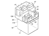
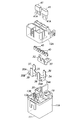
- the starter magnet switch 10 has a switch casing 11 made of an electrically insulating material such as plastics, and a terminal holder 12 made of a material such as plastics attached to the upper end of the switch casing 11.
- the switch casing 11 is positioned on the lower side, and the terminal holder 12 is coupled to the upper end thereof.
- the electromagnetic switch device can be attached in any posture.
- the switch casing 11 contains an electromagnetic switch 18 in a sealed manner, and the electromagnetic switch 18 includes an electromagnetic coil 13, a plunger 14, a pair of fixed contact members 15, 16 and a movable contact member 17.
- the electromagnetic coil 13 When the electromagnetic coil 13 is excited, the movable contact member 17 comes into contact with the fixed contact members 15 and 16, the both fixed contact members are electrically connected to each other, and the electromagnetic coil 13 is demagnetized, whereby the movable contact member 17 is illustrated.
- the spring force of the spring that is not separated separates from the fixed contact members 15 and 16 and interrupts conduction between the two fixed contact members.
- the coil terminals 13 ⁇ / b> A and 13 ⁇ / b> B of the electromagnetic coil 13 protrude upward from the upper end portion of the switch casing 11.
- the switch casing 11 is provided with a power contact terminal 19 that is integrated with the fixed contact member 15 and a switch output terminal 20 that is integrated with the fixed contact member 16.
- the upper end portion of the power terminal 19 and the upper end portion of the switch output terminal 20 are exposed to protrude slightly above the upper end portion of the switch casing 11.
- a battery power source 100 is electrically connected to the upper end of the power terminal 19, and a starter motor 101 is electrically connected to the upper end of the switch output terminal 20.
- the fixed contact member 15 and the power terminal 19 may be separate parts and conductively connected to each other.
- the fixed contact member 16 and the switch output terminal 20 may be separate parts and conductively connected to each other.
- the terminal holder 12 is paired with a power supply side terminal piece 33 that is conductively connected to the power supply terminal 19 and has two power supply side fuse connection terminals 31 and 32, and a corresponding one of the power supply side fuse connection terminals 31 and 32, respectively.
- a pair of output side terminal pieces 34 and 35 that are integrally provided with output side fuse connection terminals 36 and 37 are attached.
- a spring piece 40 formed by bending a resilient conductive plate material into a required shape is fixed to each of the fuse connection terminals 31, 32, 36, and 37.
- Each pair of blade fuses 41 is connected to a corresponding pair of fuse connection terminals by inserting a flat leg piece 41A into a spring piece 40 fixed to the corresponding fuse connection terminal.
- Each spring piece 40 elastically holds the corresponding leg piece 41A in a detachable manner.
- the output terminal 38 to which the first electric load 102 including a normal headlight and a taillight is to be connected is provided on one of the output side terminal pieces 34.
- the other output side terminal piece 35 is provided with an output terminal 39 to which a second electric load 103 including a normal fuel injection valve and an engine control unit is to be connected.
- these terminals are all arranged in one row so that the power supply side fuse connection terminals 31 and 32 are adjacent to each other and the output side fuse connection terminals 36 and 37 occupy their outer positions. Yes.
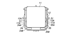
- Each of the output side terminal pieces 34 and 35 is formed by press-molding a conductive plate material, and has a horizontal main body portion. From the main body portion, a pair of heat radiation pieces 34A and 34B bent downward. , 35A, 35B are extended.
- the terminal holder 12 has an outer peripheral wall 12A to be fitted to the upper end of the switch casing 11, and a small gap 51 is defined between the lower end of the outer peripheral wall 12A and the side wall surface 11A of the switch casing 11.
- the heat radiating piece portions 34A, 34B, 35A, 35B of the output side terminal pieces 34, 35 extend in the lateral direction so as to be orthogonal to each other, and one side 34A, 35A corresponds to the gap 51. It has rushed into the part to be. Since the gap 51 communicates with the outside air through the lower end portion, it is possible to realize a suitable heat transfer by convection from the terminal piece to the outside air. Since the heat radiation pieces 34A and 35A extend vertically along the side wall surface 11A of the switch casing 11, the surface area of the heat radiation pieces 34A and 34B can be increased without increasing the size of the electromagnetic switch device 10. .
- the bending length of the heat radiating piece portions 34A and 35A may be set to an appropriate value according to the temperature characteristics of the output side fuse connection terminals 34 and 35, and if within the height range of the switch casing 11, The bending length of the heat dissipating pieces 34A and 35A may be long, and this does not increase the size of the electromagnetic switch device.
- the other heat radiating piece 34B, 35B is inside the outer peripheral wall 12A and is not exposed to the outside, so that protection is achieved, and the heat radiating piece 34B, 35B comes into contact with an external conductor to cause a short circuit, ground It is possible to prevent entanglement from occurring.
- the heat radiation pieces 34A, 35A of the output side terminal pieces 34, 35 are in a state where one surface is in contact with the inner surface (inner surface) of the outer peripheral wall 12A of the terminal holder 12 (overlapping state). Has entered. Thereby, heat is dissipated by conducting heat transfer from the heat dissipating pieces 34 ⁇ / b> A and 35 ⁇ / b> A to the terminal holder 12 and the switch casing 11. Further, the heat radiating pieces 34A and 35A also serve as a reinforcing member for the outer peripheral wall 12A of the terminal holder 12.
- the outer peripheral wall 12A is reinforced from the inside, and the terminal holder 12 is deformed by an external force that can be applied to the electromagnetic switch device 10. It can be prevented from being damaged.
- the output side terminal pieces 34 and 35 are arranged outside, the output side terminal pieces 34 and 35 are provided with the heat radiation pieces 34A and 35A, but the power source side terminal pieces 31 and 32 are outside.
- the power supply side terminal pieces 31 and 32 may be provided with heat dissipation pieces equivalent to the heat dissipation pieces 34A and 35A.
- these heat radiating piece parts can be provided only on one terminal piece without departing from the concept of the present invention.
- FIG. 1 is an electric circuit diagram showing an embodiment in which an electromagnetic switch device according to the present invention is applied to a starter magnet switch of a motorcycle. It is a longitudinal cross-sectional view of the electromagnetic switch apparatus by this embodiment. It is a bottom view of the electromagnetic switch device by this embodiment. It is a perspective view of the electromagnetic switch apparatus by this embodiment. It is a disassembled perspective view of the electromagnetic switch apparatus by this embodiment.
Landscapes
- Engineering & Computer Science (AREA)
- Physics & Mathematics (AREA)
- Electromagnetism (AREA)
- Chemical & Material Sciences (AREA)
- Combustion & Propulsion (AREA)
- Mechanical Engineering (AREA)
- General Engineering & Computer Science (AREA)
- Switch Cases, Indication, And Locking (AREA)
Abstract
Description
11 スイッチケーシング
11A 外周壁
12 端子ホルダ
12A 側壁面
13 電磁コイル
14 プランジャ
15、16 固定接点部材
17 可動接点部材
18 電磁スイッチ
19 電源端子
20 スイッチ出力端子
31、32 電源側ヒューズ接続端子
33 電源側端子片
34、35 出力側端子片
34A、35A 放熱片部
34B、35B 放熱片部
36、37 出力側ヒューズ接続端子
38、39 出力端子
40 ばね片
41 ブレードヒューズ
41A 脚片
51 空隙
Claims (7)
- 電磁スイッチ装置であって、
開放端を有し、かつ電磁コイル、プランジャ及び接点アセンブリを内蔵するスイッチケーシングと、
前記スイッチケーシングの前記開放端に嵌装され、少なくとも1つの電源側端子片及び少なくとも1つの出力側端子片を受容する端子ホルダとを有し、
前記端子ホルダが、前記スイッチケーシングの側壁に対してラップし、かつ空隙をおいて対向する外周壁を有し、
前記端子片の少なくとも1つが、前記スイッチケーシングの前記側壁と、前記端子ホルダの前記外周壁との間の前記空隙内に突入する放熱用延長部を有する電磁スイッチ装置。 - 前記電源側端子片からは電源側ヒューズ接続端子が延出し、前記出力側端子片からは出力側ヒューズ接続端子が延出している請求項1に記載の電磁スイッチ装置。
- 当該装置が、それぞれ2つの前記出力側端子片を有し、かつ各出力側端子片から出力側ヒューズ接続端子が延出し、前記電源側端子片からは、前記両出力側端子片の対応する前記出力側ヒューズ接続端子と対をなす2つの電源側ヒューズ接続端子が延出する請求項2に記載の電磁スイッチ装置。
- 前記接点アセンブリが、1対の固定接点部材と、前記プランジャに結合された1つの可動接点部材とを有し、
前記スイッチケーシングが、更に、対応する前記固定接点部材にそれぞれ接続されたスイッチケーシング端子を有し、前記スイッチケーシング端子の一方が前記出力側端子片に電気的に接続され、前記スイッチケーシング端子の他方は、スタータに電気的に接続されるべく構成される請求項1に記載の電磁スイッチ装置。 - 前記端子ホルダが前記スイッチケーシングに対して軸線方向に嵌装され、前記出力側端子片は、前記軸線方向に対して直交する方向に延在する本体部を有し、前記放熱用延長部が、前記本体部の一部を、前記端子ホルダの前記外周壁の内面に向けて折り曲げることにより形成されている請求項1に記載の電磁スイッチ装置。
- 前記出力側ヒューズ接続端子が、前記電源側ヒューズ接続端子に対して外側位置を占めるように、これらの端子が全て1列に配置されている請求項2に記載の電磁スイッチ装置。
- 前記放熱用延長部が、前記端子ホルダの前記外周壁に対して密接している請求項1に記載の電磁スイッチ装置。
Priority Applications (3)
| Application Number | Priority Date | Filing Date | Title |
|---|---|---|---|
| CN2008801179261A CN101874280B (zh) | 2007-12-26 | 2008-12-12 | 电磁开关装置 |
| EP08864903.3A EP2226826B1 (en) | 2007-12-26 | 2008-12-12 | Electromagnetic switch device |
| BRPI0821607-0A BRPI0821607B1 (pt) | 2007-12-26 | 2008-12-12 | Dispositivo de interruptor eletromagnético |
Applications Claiming Priority (2)
| Application Number | Priority Date | Filing Date | Title |
|---|---|---|---|
| JP2007-333465 | 2007-12-26 | ||
| JP2007333465A JP4950871B2 (ja) | 2007-12-26 | 2007-12-26 | 電磁スイッチ装置 |
Publications (1)
| Publication Number | Publication Date |
|---|---|
| WO2009081535A1 true WO2009081535A1 (ja) | 2009-07-02 |
Family
ID=40800853
Family Applications (1)
| Application Number | Title | Priority Date | Filing Date |
|---|---|---|---|
| PCT/JP2008/003745 Ceased WO2009081535A1 (ja) | 2007-12-26 | 2008-12-12 | 電磁スイッチ装置 |
Country Status (5)
| Country | Link |
|---|---|
| EP (1) | EP2226826B1 (ja) |
| JP (1) | JP4950871B2 (ja) |
| CN (1) | CN101874280B (ja) |
| BR (1) | BRPI0821607B1 (ja) |
| WO (1) | WO2009081535A1 (ja) |
Cited By (5)
| Publication number | Priority date | Publication date | Assignee | Title |
|---|---|---|---|---|
| WO2011110445A3 (de) * | 2010-03-12 | 2012-02-02 | Robert Bosch Gmbh | Vorrichtung zum starten einer verbrennungskraftmaschine |
| CN105264720A (zh) * | 2013-06-11 | 2016-01-20 | 矢崎总业株式会社 | 屏蔽连接器 |
| CN108493075A (zh) * | 2018-04-12 | 2018-09-04 | 谢井峰 | 具有线路保护功能的继电器 |
| JP2019197762A (ja) * | 2018-05-07 | 2019-11-14 | パナソニックIpマネジメント株式会社 | 電子部品 |
| WO2024190321A1 (ja) * | 2023-03-13 | 2024-09-19 | オムロン株式会社 | 電磁継電器 |
Families Citing this family (4)
| Publication number | Priority date | Publication date | Assignee | Title |
|---|---|---|---|---|
| KR101381427B1 (ko) * | 2013-05-14 | 2014-04-04 | (주)에이치엔티 | 전류 스위치 개별 퓨즈 구조 |
| CN103985607B (zh) * | 2014-05-15 | 2015-12-02 | 宁波福特继电器有限公司 | 一种带推动机构的大功率电磁继电器 |
| DE102015224278A1 (de) * | 2015-12-04 | 2017-06-08 | Robert Bosch Gmbh | Elektromagnetisches Relais, insbesondere Starterrelais für eine Startvorrichtung |
| WO2022109594A1 (en) * | 2020-11-20 | 2022-05-27 | Wohner Besitz Gmbh | Fuse holder |
Citations (3)
| Publication number | Priority date | Publication date | Assignee | Title |
|---|---|---|---|---|
| JPS4928159U (ja) * | 1972-06-15 | 1974-03-11 | ||
| JPS6185746A (ja) | 1984-10-03 | 1986-05-01 | 株式会社 本田ロツク | ヒユ−ズ回路ユニツト |
| JPH1122602A (ja) * | 1997-07-01 | 1999-01-26 | Mitsubishi Electric Corp | スタータ用マグネットスイッチ |
Family Cites Families (6)
| Publication number | Priority date | Publication date | Assignee | Title |
|---|---|---|---|---|
| FR1209198A (fr) * | 1958-06-02 | 1960-02-29 | Telemecanique Electrique | Perfectionnements aux tableaux d'appareillage électrique |
| US3796978A (en) * | 1972-06-05 | 1974-03-12 | Westinghouse Electric Corp | Electromagnetic contactor with fuse block |
| JPS4928159A (ja) * | 1972-07-17 | 1974-03-13 | ||
| US4692835A (en) * | 1984-10-03 | 1987-09-08 | Honda Giken Kogyo K.K. | Fuse circuit unit for combination with an electromagnetic switch |
| CN2781554Y (zh) * | 2005-04-15 | 2006-05-17 | 温州开控电气有限公司 | 一种带有绝缘隔热片和散热透气孔的继电器 |
| CN2870147Y (zh) * | 2006-03-17 | 2007-02-14 | 宁波天波港联电子有限公司 | 小型大功率电磁继电器 |
-
2007
- 2007-12-26 JP JP2007333465A patent/JP4950871B2/ja not_active Expired - Fee Related
-
2008
- 2008-12-12 CN CN2008801179261A patent/CN101874280B/zh not_active Expired - Fee Related
- 2008-12-12 EP EP08864903.3A patent/EP2226826B1/en not_active Not-in-force
- 2008-12-12 BR BRPI0821607-0A patent/BRPI0821607B1/pt not_active IP Right Cessation
- 2008-12-12 WO PCT/JP2008/003745 patent/WO2009081535A1/ja not_active Ceased
Patent Citations (3)
| Publication number | Priority date | Publication date | Assignee | Title |
|---|---|---|---|---|
| JPS4928159U (ja) * | 1972-06-15 | 1974-03-11 | ||
| JPS6185746A (ja) | 1984-10-03 | 1986-05-01 | 株式会社 本田ロツク | ヒユ−ズ回路ユニツト |
| JPH1122602A (ja) * | 1997-07-01 | 1999-01-26 | Mitsubishi Electric Corp | スタータ用マグネットスイッチ |
Non-Patent Citations (1)
| Title |
|---|
| See also references of EP2226826A4 * |
Cited By (8)
| Publication number | Priority date | Publication date | Assignee | Title |
|---|---|---|---|---|
| WO2011110445A3 (de) * | 2010-03-12 | 2012-02-02 | Robert Bosch Gmbh | Vorrichtung zum starten einer verbrennungskraftmaschine |
| CN102782306A (zh) * | 2010-03-12 | 2012-11-14 | 罗伯特·博世有限公司 | 用于起动内燃机的装置 |
| CN105264720A (zh) * | 2013-06-11 | 2016-01-20 | 矢崎总业株式会社 | 屏蔽连接器 |
| CN108493075A (zh) * | 2018-04-12 | 2018-09-04 | 谢井峰 | 具有线路保护功能的继电器 |
| CN108493075B (zh) * | 2018-04-12 | 2024-07-19 | 顺科电气技术(深圳)有限公司 | 具有线路保护功能的继电器 |
| JP2019197762A (ja) * | 2018-05-07 | 2019-11-14 | パナソニックIpマネジメント株式会社 | 電子部品 |
| JP7209476B2 (ja) | 2018-05-07 | 2023-01-20 | ミネベアミツミ株式会社 | 電子部品 |
| WO2024190321A1 (ja) * | 2023-03-13 | 2024-09-19 | オムロン株式会社 | 電磁継電器 |
Also Published As
| Publication number | Publication date |
|---|---|
| BRPI0821607B1 (pt) | 2019-08-20 |
| EP2226826B1 (en) | 2014-02-26 |
| EP2226826A1 (en) | 2010-09-08 |
| BRPI0821607A2 (pt) | 2015-06-16 |
| JP4950871B2 (ja) | 2012-06-13 |
| EP2226826A4 (en) | 2013-08-21 |
| CN101874280B (zh) | 2013-03-20 |
| CN101874280A (zh) | 2010-10-27 |
| JP2009158221A (ja) | 2009-07-16 |
Similar Documents
| Publication | Publication Date | Title |
|---|---|---|
| WO2009081535A1 (ja) | 電磁スイッチ装置 | |
| CN107112734B (zh) | 蓄电单元 | |
| US20150230352A1 (en) | Electrical junction box | |
| CN113994774A (zh) | 电路结构体 | |
| WO2013069616A1 (ja) | 電気接続箱 | |
| JP5582357B2 (ja) | 電気接続箱 | |
| JP4858508B2 (ja) | 電磁開閉装置 | |
| JP2006191772A (ja) | 電気接続箱 | |
| JP4686218B2 (ja) | メタルコア基板及びこれを利用した車載システム | |
| JP3876813B2 (ja) | 電気接続箱 | |
| JP4732789B2 (ja) | スイッチングユニット | |
| JP3918470B2 (ja) | 電磁リレー | |
| JP2019208342A (ja) | 電気接続箱 | |
| JP2003087934A (ja) | 電気接続箱 | |
| JP7719124B2 (ja) | 電気接続箱 | |
| JP4653541B2 (ja) | スイッチングユニット | |
| KR102540468B1 (ko) | 부식방지용 이종금속이 구비된 듀얼 타입 ptc 히터 | |
| JP4783054B2 (ja) | スイッチングユニット | |
| CN115398762B (zh) | 电路单元 | |
| US20250372971A1 (en) | Electrical connection unit | |
| US20250372930A1 (en) | Electrical connection unit | |
| JP4579034B2 (ja) | スイッチングユニット | |
| JP5835198B2 (ja) | ワイヤーハーネスシステム | |
| CN121263868A (zh) | 电气接线箱 | |
| CN120693672A (zh) | 电磁继电器 |
Legal Events
| Date | Code | Title | Description |
|---|---|---|---|
| WWE | Wipo information: entry into national phase |
Ref document number: 200880117926.1 Country of ref document: CN |
|
| 121 | Ep: the epo has been informed by wipo that ep was designated in this application |
Ref document number: 08864903 Country of ref document: EP Kind code of ref document: A1 |
|
| WWE | Wipo information: entry into national phase |
Ref document number: 2008864903 Country of ref document: EP |
|
| DPE2 | Request for preliminary examination filed before expiration of 19th month from priority date (pct application filed from 20040101) | ||
| WWE | Wipo information: entry into national phase |
Ref document number: 1898/KOLNP/2010 Country of ref document: IN |
|
| NENP | Non-entry into the national phase |
Ref country code: DE |
|
| ENP | Entry into the national phase |
Ref document number: PI0821607 Country of ref document: BR Kind code of ref document: A2 Effective date: 20100623 |