WO2009084136A1 - 異材継手構造、該異材継手構造を備えるタンク用スカート、該タンク用スカートを備える輸送船、及び異種金属部材の接合方法 - Google Patents
異材継手構造、該異材継手構造を備えるタンク用スカート、該タンク用スカートを備える輸送船、及び異種金属部材の接合方法 Download PDFInfo
- Publication number
- WO2009084136A1 WO2009084136A1 PCT/JP2008/002556 JP2008002556W WO2009084136A1 WO 2009084136 A1 WO2009084136 A1 WO 2009084136A1 JP 2008002556 W JP2008002556 W JP 2008002556W WO 2009084136 A1 WO2009084136 A1 WO 2009084136A1
- Authority
- WO
- WIPO (PCT)
- Prior art keywords
- groove
- tank
- side support
- insertion portion
- joint structure
- Prior art date
- Legal status (The legal status is an assumption and is not a legal conclusion. Google has not performed a legal analysis and makes no representation as to the accuracy of the status listed.)
- Ceased
Links
Images






Classifications
-
- B—PERFORMING OPERATIONS; TRANSPORTING
- B23—MACHINE TOOLS; METAL-WORKING NOT OTHERWISE PROVIDED FOR
- B23K—SOLDERING OR UNSOLDERING; WELDING; CLADDING OR PLATING BY SOLDERING OR WELDING; CUTTING BY APPLYING HEAT LOCALLY, e.g. FLAME CUTTING; WORKING BY LASER BEAM
- B23K20/00—Non-electric welding by applying impact or other pressure, with or without the application of heat, e.g. cladding or plating
- B23K20/12—Non-electric welding by applying impact or other pressure, with or without the application of heat, e.g. cladding or plating the heat being generated by friction; Friction welding
- B23K20/122—Non-electric welding by applying impact or other pressure, with or without the application of heat, e.g. cladding or plating the heat being generated by friction; Friction welding using a non-consumable tool, e.g. friction stir welding
- B23K20/1265—Non-butt welded joints, e.g. overlap-joints, T-joints or spot welds
-
- B—PERFORMING OPERATIONS; TRANSPORTING
- B23—MACHINE TOOLS; METAL-WORKING NOT OTHERWISE PROVIDED FOR
- B23K—SOLDERING OR UNSOLDERING; WELDING; CLADDING OR PLATING BY SOLDERING OR WELDING; CUTTING BY APPLYING HEAT LOCALLY, e.g. FLAME CUTTING; WORKING BY LASER BEAM
- B23K20/00—Non-electric welding by applying impact or other pressure, with or without the application of heat, e.g. cladding or plating
- B23K20/22—Non-electric welding by applying impact or other pressure, with or without the application of heat, e.g. cladding or plating taking account of the properties of the materials to be welded
- B23K20/227—Non-electric welding by applying impact or other pressure, with or without the application of heat, e.g. cladding or plating taking account of the properties of the materials to be welded with ferrous layer
- B23K20/2275—Non-electric welding by applying impact or other pressure, with or without the application of heat, e.g. cladding or plating taking account of the properties of the materials to be welded with ferrous layer the other layer being aluminium
-
- B—PERFORMING OPERATIONS; TRANSPORTING
- B23—MACHINE TOOLS; METAL-WORKING NOT OTHERWISE PROVIDED FOR
- B23K—SOLDERING OR UNSOLDERING; WELDING; CLADDING OR PLATING BY SOLDERING OR WELDING; CUTTING BY APPLYING HEAT LOCALLY, e.g. FLAME CUTTING; WORKING BY LASER BEAM
- B23K33/00—Specially-profiled edge portions of workpieces for making soldering or welding connections; Filling the seams formed thereby
- B23K33/004—Filling of continuous seams
-
- B—PERFORMING OPERATIONS; TRANSPORTING
- B63—SHIPS OR OTHER WATERBORNE VESSELS; RELATED EQUIPMENT
- B63B—SHIPS OR OTHER WATERBORNE VESSELS; EQUIPMENT FOR SHIPPING
- B63B25/00—Load-accommodating arrangements, e.g. stowing, trimming; Vessels characterised thereby
- B63B25/02—Load-accommodating arrangements, e.g. stowing, trimming; Vessels characterised thereby for bulk goods
- B63B25/08—Load-accommodating arrangements, e.g. stowing, trimming; Vessels characterised thereby for bulk goods fluid
- B63B25/12—Load-accommodating arrangements, e.g. stowing, trimming; Vessels characterised thereby for bulk goods fluid closed
- B63B25/16—Load-accommodating arrangements, e.g. stowing, trimming; Vessels characterised thereby for bulk goods fluid closed heat-insulated
-
- F—MECHANICAL ENGINEERING; LIGHTING; HEATING; WEAPONS; BLASTING
- F17—STORING OR DISTRIBUTING GASES OR LIQUIDS
- F17C—VESSELS FOR CONTAINING OR STORING COMPRESSED, LIQUEFIED OR SOLIDIFIED GASES; FIXED-CAPACITY GAS-HOLDERS; FILLING VESSELS WITH, OR DISCHARGING FROM VESSELS, COMPRESSED, LIQUEFIED, OR SOLIDIFIED GASES
- F17C3/00—Vessels not under pressure
- F17C3/02—Vessels not under pressure with provision for thermal insulation
- F17C3/025—Bulk storage in barges or on ships
-
- B—PERFORMING OPERATIONS; TRANSPORTING
- B23—MACHINE TOOLS; METAL-WORKING NOT OTHERWISE PROVIDED FOR
- B23K—SOLDERING OR UNSOLDERING; WELDING; CLADDING OR PLATING BY SOLDERING OR WELDING; CUTTING BY APPLYING HEAT LOCALLY, e.g. FLAME CUTTING; WORKING BY LASER BEAM
- B23K2101/00—Articles made by soldering, welding or cutting
- B23K2101/04—Tubular or hollow articles
- B23K2101/12—Vessels
-
- B—PERFORMING OPERATIONS; TRANSPORTING
- B23—MACHINE TOOLS; METAL-WORKING NOT OTHERWISE PROVIDED FOR
- B23K—SOLDERING OR UNSOLDERING; WELDING; CLADDING OR PLATING BY SOLDERING OR WELDING; CUTTING BY APPLYING HEAT LOCALLY, e.g. FLAME CUTTING; WORKING BY LASER BEAM
- B23K2103/00—Materials to be soldered, welded or cut
- B23K2103/18—Dissimilar materials
- B23K2103/20—Ferrous alloys and aluminium or alloys thereof
-
- F—MECHANICAL ENGINEERING; LIGHTING; HEATING; WEAPONS; BLASTING
- F16—ENGINEERING ELEMENTS AND UNITS; GENERAL MEASURES FOR PRODUCING AND MAINTAINING EFFECTIVE FUNCTIONING OF MACHINES OR INSTALLATIONS; THERMAL INSULATION IN GENERAL
- F16B—DEVICES FOR FASTENING OR SECURING CONSTRUCTIONAL ELEMENTS OR MACHINE PARTS TOGETHER, e.g. NAILS, BOLTS, CIRCLIPS, CLAMPS, CLIPS OR WEDGES; JOINTS OR JOINTING
- F16B5/00—Joining sheets or plates, e.g. panels, to one another or to strips or bars parallel to them
- F16B5/08—Joining sheets or plates, e.g. panels, to one another or to strips or bars parallel to them by means of welds or the like
-
- F—MECHANICAL ENGINEERING; LIGHTING; HEATING; WEAPONS; BLASTING
- F17—STORING OR DISTRIBUTING GASES OR LIQUIDS
- F17C—VESSELS FOR CONTAINING OR STORING COMPRESSED, LIQUEFIED OR SOLIDIFIED GASES; FIXED-CAPACITY GAS-HOLDERS; FILLING VESSELS WITH, OR DISCHARGING FROM VESSELS, COMPRESSED, LIQUEFIED, OR SOLIDIFIED GASES
- F17C2201/00—Vessel construction, in particular geometry, arrangement or size
- F17C2201/01—Shape
- F17C2201/0128—Shape spherical or elliptical
-
- F—MECHANICAL ENGINEERING; LIGHTING; HEATING; WEAPONS; BLASTING
- F17—STORING OR DISTRIBUTING GASES OR LIQUIDS
- F17C—VESSELS FOR CONTAINING OR STORING COMPRESSED, LIQUEFIED OR SOLIDIFIED GASES; FIXED-CAPACITY GAS-HOLDERS; FILLING VESSELS WITH, OR DISCHARGING FROM VESSELS, COMPRESSED, LIQUEFIED, OR SOLIDIFIED GASES
- F17C2201/00—Vessel construction, in particular geometry, arrangement or size
- F17C2201/05—Size
- F17C2201/052—Size large (>1000 m3)
-
- F—MECHANICAL ENGINEERING; LIGHTING; HEATING; WEAPONS; BLASTING
- F17—STORING OR DISTRIBUTING GASES OR LIQUIDS
- F17C—VESSELS FOR CONTAINING OR STORING COMPRESSED, LIQUEFIED OR SOLIDIFIED GASES; FIXED-CAPACITY GAS-HOLDERS; FILLING VESSELS WITH, OR DISCHARGING FROM VESSELS, COMPRESSED, LIQUEFIED, OR SOLIDIFIED GASES
- F17C2205/00—Vessel construction, in particular mounting arrangements, attachments or identifications means
- F17C2205/01—Mounting arrangements
- F17C2205/0153—Details of mounting arrangements
- F17C2205/0192—Details of mounting arrangements with external bearing means
-
- F—MECHANICAL ENGINEERING; LIGHTING; HEATING; WEAPONS; BLASTING
- F17—STORING OR DISTRIBUTING GASES OR LIQUIDS
- F17C—VESSELS FOR CONTAINING OR STORING COMPRESSED, LIQUEFIED OR SOLIDIFIED GASES; FIXED-CAPACITY GAS-HOLDERS; FILLING VESSELS WITH, OR DISCHARGING FROM VESSELS, COMPRESSED, LIQUEFIED, OR SOLIDIFIED GASES
- F17C2221/00—Handled fluid, in particular type of fluid
- F17C2221/03—Mixtures
- F17C2221/032—Hydrocarbons
- F17C2221/033—Methane, e.g. natural gas, CNG, LNG, GNL, GNC, PLNG
-
- F—MECHANICAL ENGINEERING; LIGHTING; HEATING; WEAPONS; BLASTING
- F17—STORING OR DISTRIBUTING GASES OR LIQUIDS
- F17C—VESSELS FOR CONTAINING OR STORING COMPRESSED, LIQUEFIED OR SOLIDIFIED GASES; FIXED-CAPACITY GAS-HOLDERS; FILLING VESSELS WITH, OR DISCHARGING FROM VESSELS, COMPRESSED, LIQUEFIED, OR SOLIDIFIED GASES
- F17C2223/00—Handled fluid before transfer, i.e. state of fluid when stored in the vessel or before transfer from the vessel
- F17C2223/01—Handled fluid before transfer, i.e. state of fluid when stored in the vessel or before transfer from the vessel characterised by the phase
- F17C2223/0146—Two-phase
- F17C2223/0153—Liquefied gas, e.g. LPG, GPL
- F17C2223/0161—Liquefied gas, e.g. LPG, GPL cryogenic, e.g. LNG, GNL, PLNG
-
- F—MECHANICAL ENGINEERING; LIGHTING; HEATING; WEAPONS; BLASTING
- F17—STORING OR DISTRIBUTING GASES OR LIQUIDS
- F17C—VESSELS FOR CONTAINING OR STORING COMPRESSED, LIQUEFIED OR SOLIDIFIED GASES; FIXED-CAPACITY GAS-HOLDERS; FILLING VESSELS WITH, OR DISCHARGING FROM VESSELS, COMPRESSED, LIQUEFIED, OR SOLIDIFIED GASES
- F17C2223/00—Handled fluid before transfer, i.e. state of fluid when stored in the vessel or before transfer from the vessel
- F17C2223/03—Handled fluid before transfer, i.e. state of fluid when stored in the vessel or before transfer from the vessel characterised by the pressure level
- F17C2223/033—Small pressure, e.g. for liquefied gas
-
- F—MECHANICAL ENGINEERING; LIGHTING; HEATING; WEAPONS; BLASTING
- F17—STORING OR DISTRIBUTING GASES OR LIQUIDS
- F17C—VESSELS FOR CONTAINING OR STORING COMPRESSED, LIQUEFIED OR SOLIDIFIED GASES; FIXED-CAPACITY GAS-HOLDERS; FILLING VESSELS WITH, OR DISCHARGING FROM VESSELS, COMPRESSED, LIQUEFIED, OR SOLIDIFIED GASES
- F17C2260/00—Purposes of gas storage and gas handling
- F17C2260/01—Improving mechanical properties or manufacturing
- F17C2260/011—Improving strength
-
- F—MECHANICAL ENGINEERING; LIGHTING; HEATING; WEAPONS; BLASTING
- F17—STORING OR DISTRIBUTING GASES OR LIQUIDS
- F17C—VESSELS FOR CONTAINING OR STORING COMPRESSED, LIQUEFIED OR SOLIDIFIED GASES; FIXED-CAPACITY GAS-HOLDERS; FILLING VESSELS WITH, OR DISCHARGING FROM VESSELS, COMPRESSED, LIQUEFIED, OR SOLIDIFIED GASES
- F17C2270/00—Applications
- F17C2270/01—Applications for fluid transport or storage
- F17C2270/0102—Applications for fluid transport or storage on or in the water
- F17C2270/0105—Ships
Definitions
- the present invention relates to a dissimilar joint structure for joining two metal members made of dissimilar metals, in particular, dissimilar metals difficult to weld to each other, and a method for joining such two metal members to each other.
- the present invention also relates to a tank skirt provided with the dissimilar joint structure and a transport ship provided with the tank skirt.
- liquid cargo transport ships examples include MOSS type LNG transport ships that store and transport LNG (liquefied natural gas) in a spherical tank.
- LNG liquefied natural gas
- the temperature of the cargo stored in the tank is extremely low (about -163 degrees Celsius).
- the tank is supported by the hull via a tank skirt so as to avoid a significant drop in the temperature of the hull itself due to this cargo.
- the hull is made of ferrous steel to ensure strength
- the tank is made of aluminum alloy to withstand low temperatures.
- the tank skirt is interposed between these dissimilar metal materials, a tank side support member formed of the same material as the tank and fixed to the tank, and a hull formed of the same material as the hull and fixed to the hull. And a side support member. Both supporting members are joined to each other by a dissimilar joint structure.
- Patent Document 1 discloses a dissimilar joint structure including a first plate-like member joined to an end portion of a tank-side support member and a second plate-like member joined to an end portion of a hull-side support member. ing. According to this dissimilar joint structure, the end surfaces of the first and second plate-like members are abutted against each other, and the abutted portions are joined by friction stir welding. By using this friction stir welding, it is possible to make the dissimilar joint structure long and to reduce the protruding length with respect to both support members as compared to the case of using explosive pressure bonding. JP 2007-153064 A
- the present invention has been made for the purpose of providing a dissimilar joint structure that can improve fatigue strength.
- the dissimilar joint structure according to the present invention is a dissimilar joint structure for joining a first metal member and a second metal member made of different metals to each other, wherein an insertion groove is formed in the first metal member, and the second An insertion part that can be inserted into the insertion groove is formed in the metal member, and the first metal member is joined to the second metal member in a state where the insertion part is inserted into the insertion groove. Yes.
- the dissimilar metal member joining method is a method of joining the first metal member and the second metal member made of dissimilar metals to each other in the insertion groove formed in the first metal member.
- a step of inserting an insertion portion formed in the second metal member; and a rotating tool of a friction stir welding apparatus is pressed against an outer surface of the first metal member, and the rotating tool is caused to enter the insertion portion side from the outer surface.
- a step of joining the first metal member to the second metal member by moving the rotating tool in the extending direction of the first metal member.
- a dissimilar metal member joining method for joining dissimilar metal members for joining a first metal member and a second metal member made of dissimilar metals to each other.
- a step of joining the first groove forming member to the insertion portion by moving the rotating tool in the extending direction of the first groove forming member, and a second side surface of the insertion portion to the second side.
- a step of covering with a groove forming member, a rotating tool of a friction stir welding apparatus is pressed against the outer surface of the second groove forming member, the rotating tool is caused to enter the insertion portion side from the outer surface, and the rotating tool is moved into the second portion Move in the extending direction of the groove forming member Accordingly, the step of joining the first groove forming member to the insertion portion, and the state where the end surface of the first metal member is in contact with the end surface of the insertion portion, the end surface of the first metal member is moved to the first portion. And a step of joining to each end face of the groove forming member and the second groove forming member.
- the tank skirt according to the present invention is characterized by having such a dissimilar joint structure, the quality of the tank skirt is improved.
- the transport ship according to the present invention includes such a tank skirt.
- FIG. 1 is a perspective view showing an appearance of an LNG transport ship according to an embodiment of the present invention.
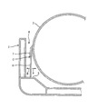
- FIG. 2 is a cross-sectional view showing a partial internal structure of the LNG transport ship according to the embodiment of the present invention.
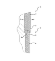
- FIG. 3 is a cross-sectional view schematically showing a main part of the tank skirt according to the embodiment of the present invention.
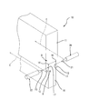
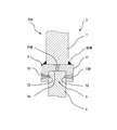
- FIG. 4 is an exploded perspective view of the dissimilar joint structure according to the first embodiment.
- Drawing 5 is an explanatory view of the manufacturing method of the dissimilar joint structure concerning a 1st embodiment.
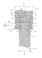
- FIG. 6 is a cross-sectional view of the dissimilar joint structure according to Embodiment 1.
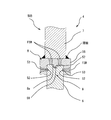
- FIG. 7 is a cross-sectional view of a dissimilar joint structure according to a modification of the first embodiment.
- FIG. 1 is a perspective view showing an appearance of an LNG transport ship according to an embodiment of the present invention.
- FIG. 2 is a cross-sectional view showing a partial internal structure of the LNG transport ship according to the embodiment of
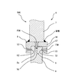
- FIG. 8 is a cross-sectional view of the dissimilar joint structure according to Embodiment 2.
- FIG. 9 is a cross-sectional view of the dissimilar joint structure according to Modification Example 1 of Embodiment 2.
- FIG. 10 is a cross-sectional view of the dissimilar joint structure according to Modification Example 2 of Embodiment 2.
- FIG. 11 is a cross-sectional view of the dissimilar joint structure according to Modification Example 3 of Embodiment 2.
- FIG. 12 is a cross-sectional view of the dissimilar joint structure according to Modification Example 4 of Embodiment 2.
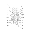
- FIG. 13 is a cross-sectional view of the dissimilar joint structure according to Embodiment 3.
- FIG. 14 is a cross-sectional view of the dissimilar joint structure according to Modification Example 1 of Embodiment 3.
- FIG. 15 is a cross-sectional view of the dissimilar joint structure according to Modification Example 2 of Embodiment 3.
- FIG. 16 is a cross-sectional view of the dissimilar joint structure according to Modification Example 3 of Embodiment 3.
- FIG. 17 is a cross-sectional view of the dissimilar joint structure according to Embodiment 4.
- FIG. 18 is a cross-sectional view of the dissimilar joint structure according to Embodiment 5.
- FIG. 19 is a cross-sectional view of the dissimilar joint structure according to Embodiment 6.
- FIG. 1 is a perspective view showing an appearance of an LNG transport ship 1 according to an embodiment of the present invention.
- An LNG transport ship 1 shown in FIG. 1 includes four spherical tanks 3 made of an aluminum alloy, and cryogenic liquefied natural gas can be stored in each tank 3.
- Each tank 3 is supported by the hull 2 via a tank skirt 4 (hereinafter simply referred to as a “skirt”) formed in a ring shape, as shown in a part of the hull 2 cut out. .
- FIG. 2 is a cross-sectional view showing a partial internal structure of the LNG transport ship 1 according to the embodiment of the present invention.
- the skirt 4 extends in the vertical direction from the base 5 of the hull 2.
- the lower end of the skirt 4 is welded to the base 5, and the upper end is welded to the outer peripheral surface of the tank 3.
- the skirt 4 includes a cylindrical hull-side support member 6 that is fixed to the base 5 and extends in the vertical direction, and a cylindrical tank-side support member 7 that is fixed to the tank 3 and extends in the vertical direction.
- Each of the hull supporting member 6 and the tank supporting member 7 has a generally cylindrical shape by connecting a plurality of (for example, 10 to 20) curved parts having the same curvature in the circumferential direction.
- the side A in FIG. 2 where the tank 3 is disposed is referred to as the inside, and the side B in FIG.
- a part of the hull supporting member 6 is made of a steel material such as stainless steel or high manganese steel, and the tank supporting member 7 is made of an aluminum alloy.
- the thickness of the tank side support member 7 made of aluminum alloy is larger than the thickness of the steel hull side support member 6.
- a dissimilar joint structure C for joining the members 6 and 7 to each other is provided at the upper end portion of the hull supporting member 6 and the lower end portion of the tank supporting member 7.
- FIG. 3 is a cross-sectional view schematically showing a part of the skirt 4.
- the dissimilar joint structure C is provided at the lower end portion of the tank side support member 7 to form the insertion groove 8 a and at the upper end portion of the hull side support member 6.
- an insertion portion 9 that can be inserted into the insertion groove 8a.
- the tank side support member 7 is shown as being partitioned from the groove forming portion 8 by a dotted line, even if the groove forming portion 8 is integrated with the tank side support member 7 as described later. This is because the first metal member of the present invention may include the tank side support member 7 and the groove forming portion 8.
- FIG. 3 is a cross-sectional view schematically showing a part of the skirt 4.
- the dissimilar joint structure C is provided at the lower end portion of the tank side support member 7 to form the insertion groove 8 a and at the upper end portion of the hull side support member 6.
- an insertion portion 9 that can be inserted into the insertion groove 8a.
- the hull side support member 6 is shown separated from the insertion portion 9 by a dotted line, even if the insertion portion 9 is integrated with the hull side support member 6 as described later. This is because the second metal member in the present invention may include the hull supporting member 6 and the insertion portion 9.
- FIG. 4 is an exploded perspective view of the dissimilar joint structure 10 according to the first embodiment of the present invention.
- the dissimilar joint structure 10 includes a groove forming portion 8 formed separately from the tank side support member 7 and an insertion portion 9 formed separately from the hull side support member 6.
- the groove forming part 8 is constituted by a groove forming member 11.
- the groove forming member 11 is separate from the tank side support member 7, but is formed of the same metal material as the tank side support member 7, such as an Al—Mn alloy.
- the groove forming member 11 is formed in a U-shaped cross section, and has a pair of side wall portions 12 and 13 and a base portion 14 connecting the pair of side wall portions 12 and 13.
- the groove forming member 11 is provided such that a pair of side wall portions 12 and 13 extend downward with respect to the base portion 14.
- the upper end surface of the base portion 14 is abutted against the lower end surface of the tank side support member 7, and in this abutted state, the mating portions of both the members 7 and 11 are butted and welded.
- both the members 7 and 11 are made of the same metal material, this welding can be easily performed.
- an insertion groove 8 a extending in the longitudinal direction, that is, the circumferential direction of the tank side support member 7 is formed between the pair of side wall portions 12 and 13 at the lower end portion of the groove forming member 11.
- the surface of the insertion groove 8 a is formed by the inner surfaces of the side wall portions 12 and 13 and the inner surface of the base wall 14.
- the corner 15 formed by the inner surface of each of the side walls 12 and 13 and the surface of the base wall 14 is formed in a round shape by machining. As a result, it is possible to prevent the corner 15 from being cracked due to stress concentration.
- the surface of the insertion groove 8a is processed so that the surface roughness is a relatively small predetermined value (6.3 ⁇ m) or less.
- the thickness of the side wall part 12 located outside the insertion groove 8a is larger than the thickness of the side wall part 13 located inside. The details of the difference in thickness and the operation relating thereto will be described later with reference to FIG.
- the insertion part 9 is constituted by an insertion member 16.
- the insertion member 16 is separate from the hull-side support member 6 but is formed by hot rolling from the same type of metal material as the hull-side support member 6, such as stainless steel.
- the lower end surface of the insertion member 16 is abutted against the upper end surface of the hull supporting member 6, and in this abutted state, the joint portions of both the members 6 and 16 are butted and welded. Since the members 6 and 16 are made of the same metal material, this welding can be easily performed.
- concave grooves 17 extending in the longitudinal direction, that is, the circumferential direction of the hull supporting member 6 are formed.
- the illustrated groove 17 has a U-shaped cross section, but the cross section of the groove may have another shape such as a semicircular shape.
- groove 17 is formed only one on each side surface, the some ditch
- a pair of corners formed by the upper end surface and each side surface of the insertion member 16 are chamfered by machining, whereby a pair of chamfered portions 18 extending in the longitudinal direction are formed on the upper end portion of the insertion member 16. Is formed.
- an oxide film may be produced
- the surface of the insertion portion 9 is subjected to surface treatment by buffing, machining, or the like. Furthermore, the surface of the insertion groove 9 is processed so that the surface roughness is a relatively small predetermined value (3 ⁇ m) or less.
- the joining method of the hull side support member 6 and the tank side support member 7 using the said dissimilar joint structure 10 is demonstrated.
- the insertion portion 9 of the insertion member 16 is inserted into the insertion groove 8 a of the groove forming member 11.
- the chamfered portion 18 is formed at the upper end portion of the insertion portion 9, the insertion portion 9 is easily introduced into the insertion groove 8a. Since the chamfered portion 18 only needs to have a shape that can be easily introduced in this manner, the chamfered portion 18 may be formed in a round shape instead of the illustrated 45-degree chamfer.
- the bonding strength between the surface of the insertion groove 8a and the surface of the insertion portion 9 is improved. Furthermore, since each surface roughness of the surface of the insertion groove 8a and the surface of the insertion portion 9 is small, the bonding strength between the surface of the insertion groove 8a and the surface of the insertion groove 9 is further improved, and the insertion portion 9 is easily introduced into the insertion groove 8a.
- the groove forming portion 8 (that is, the groove forming member 11 constituting a part of the first metal member) is joined to the insertion portion 9 (that is, the inserting member 16 constituting a part of the second metal member).
- the friction stir welding method is used is illustrated.
- This friction stir welding method is a method in which frictional heat is generated by pressing a rotating tool of a friction stir welding apparatus made of a material harder than each of two joining members against one of the joining members and moving the rotating tool while rotating.
- One of the joining members is fluidized, and one of the fluidized joining members is joined to the other of the joining members.
- the solid phase portions can be joined while being integrated, even a long material can be continuously joined in the longitudinal direction without causing thermal distortion.
- the solid-phase joining uses the flow of the metal material caused by frictional heat between the rotating tool and the joining member, the joining member can be joined without melting, and the joining member is not easily deformed before and after joining.
- the rotary tool 21 of the friction stir welding apparatus 20 is brought into contact with the outer surface of the inner side wall portion 13.
- the position where the rotary tool 21 is brought into contact is a position corresponding to the concave groove 17 of the insertion portion 9 on each side surface of the groove forming member. That is, when a plurality of concave grooves 17 are formed on each side surface, the rotary tool 21 is inserted according to the number of concave grooves 17.
- frictional heat is generated in the side wall portion 13, and the peripheral portion of the side wall portion 13 around the rotary tool 21 is fluidized by this heat.
- the rotary tool 23 of the friction stir welding apparatus 22 is brought into contact with the outer surface of the outer side wall portion 12, the rotary tool 23 enters the thickness direction from the outer surface toward the concave groove 17, and the rotary tool 23 is elongated. Move along the direction.
- frictional heat is generated in the side wall portion 12, the peripheral portion of the rotary tool 23 in the side wall portion 13 is fluidized, the side wall portion 12 is agitated while receiving pressure, and the metal material constituting the side wall portion 13 is recessed 17. Get into every corner.
- the surface of the concave groove 17 becomes an active new surface in the same manner as described above, and the active metal material forming the side wall portion 12 is pressed into the concave groove 17, so that the side wall portion 12 outside the groove forming portion 8. Can be firmly joined to the insertion portion 8.
- FIG. 5 shows that the rotary tool is pressed from both sides
- the insertion portion 9 is laid in a state where it is inserted into the insertion groove 8a on a work table (not shown) in the factory and faces upward.
- a rotating tool is pressed against the outer surface of the side wall portion 13 from above, and then the groove forming member 11 and the insertion member 16 are turned over to rotate the rotating tool from above against the outer surface of the side wall portion 12 facing upward. Press to perform the joining work.
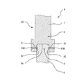
- FIG. 6 is a sectional view of the dissimilar joint structure 10 manufactured through the above steps.
- the dissimilar joint structure 10 is configured by inserting the insertion portion 9 into the insertion groove 8 a, and the joining portion is complicated and the joining portions overlap each other. Yes.
- it is hard to produce a joint defect compared with what is comprised by mutually making planes face-to-face like the past, and the fatigue strength of the dissimilar joint structure 10 improves.
- the joint portion is difficult to come off, and the fatigue strength around the dissimilar joint structure 10 is improved.
- the surface roughness is reduced or the oxide film is removed, it is possible to make it difficult to remove the joint portion.
- the fluidized metal material forming the groove forming member 11 enters the concave groove 17 formed on the insertion portion 9 side, and solidifies here to be firmly joined to the insertion portion 9.
- the groove forming member 11 is formed with the convex portion 19 projecting from the surface of the insertion groove 8a into the concave groove 17, whereby the bonding strength between the groove forming member 11 and the insertion portion 9 is improved as an anchor effect. Higher.
- the size of the dissimilar joint structure 10 can be increased in the longitudinal direction as compared with the case of using explosive pressure bonding. For this reason, the number of the plurality of curved parts constituting the hull supporting member 6 and the tank supporting member 7 can be reduced. For this reason, the manufacturing cost of the skirt 4 can be suppressed, and the production efficiency of the skirt 4 is improved.
- the thickness of the groove forming member 11 is d1 (about 50 to 120 mm), and the width of the insertion groove 8a is d2 (about 30 to 80 mm).
- the tank 3 tends to contract because the cryogenic natural gas is mounted in the tank 3, so that the upper end of the tank-side support member 7 faces inward. Bend.
- the thickness d3 of the inner side wall portion 13 is such that it is compressed only by a small compressive force and does not buckle, and the thickness d4 of the outer side wall portion 12 is pulled by the side wall portion 12. However, no damage will occur.
- the thickness d3 is larger than (d1-d2) / 4.
- the thickness d5 of the insertion member 16 is slightly smaller than the width d2 of the insertion groove 8a.
- the depth d6 of the insertion groove 8a is appropriately designed according to the number of concave grooves 17 on each side surface and the height d7 of the concave grooves 17.
- the depth d8 of the concave groove 17 is appropriately designed according to the thickness d2 of the insertion member 16.
- the surface of the insertion groove 8a and / or the surface of the insertion portion 9 may be subjected to rust prevention treatment such as plating.
- a rust preventive film is generated on the treated surface, but the rust preventive film can be peeled off by the metal material stirred by the action of the rotary tool.
- the rust preventive film is peeled off, an active new surface appears and the bonding strength is improved.
- production efficiency improves since the process which peels a rust preventive film can be performed simultaneously with the process of joining, production efficiency improves.
- FIG. 7 shows a dissimilar joint structure 10A according to a modification of the first embodiment.
- the same components as those described above are denoted by the same reference numerals, and detailed description thereof is omitted.
- a waterproof paint 30 is applied from the outside of the side wall portion 13 inside the groove forming member 11 to the inside side surface of the insertion member 16.
- the waterproof paint 30 is applied from the outside of the side wall portion outside the groove forming member 11 to the outside side surface of the insertion member 16. This painting step can be performed after the groove forming member 11 and the insertion member 16 are connected to each other by friction stir welding.
- the boundary portion 31 between the groove forming member 11 and the insertion member 16 is covered with the waterproof paint 30. For this reason, it is possible to prevent moisture from entering from the boundary portion 31 into the insertion groove 8a. Thereby, the electrolytic corrosion of the dissimilar joint structure 10A can be prevented.
- FIG. 8 shows a dissimilar joint structure 40 according to the second embodiment.
- the dissimilar joint structure 40 includes a groove forming portion 8 formed as a separate member from the tank side support member 7 and an insertion portion 9 formed as a separate member from the hull side support member 6. ing.
- the groove forming portion 8 is constituted by a groove forming member 41.
- the groove forming member 41 is separate from the tank side support member 7, but is formed of the same metal material as the tank side support member 7, such as an Al—Mn alloy.
- the groove forming member 41 is formed in a flat plate shape, and the width of the groove forming member 41 is longer than the thickness of the tank side support member 7.
- the joint portion of both members 7 and 41 is fillet welded. Since both members 7 and 41 are made of the same metal material, this welding can be easily performed.
- the insertion part 9 is constituted by an insertion member 42.
- the insertion member 42 is separate from the hull-side support member 6 but is formed by hot rolling from the same type of metal material as the hull-side support member 6, such as stainless steel.
- the insertion member 42 is formed in a flat plate shape, and the width of the insertion member 41 is substantially equal to the width of the groove forming member 41 and is longer than the thickness of the hull supporting member 6.
- the lower end surface of the insertion member 42 is abutted against the upper end surface of the hull side support member 6, the lower end surface of the groove forming member 41 protrudes to both sides with respect to the hull side support member 6. In this projecting portion, the joint portion between the members 6 and 42 is fillet welded. Since both the members 6 and 42 are made of the same metal material, this welding can be easily performed.
- the illustrated groove 17 has a U-shaped cross section, but the cross section of the groove may have another shape such as a semicircular shape.
- groove 17 is formed only in one on each side surface, the some ditch
- the convex portion 43 forms the insertion portion 9.
- the insertion member 42 is formed in the insertion groove 8a formed in the groove forming member 41.
- the portion 9 is inserted, and the groove forming member 41 is assembled to the insertion member 42.
- a rotary tool (not shown) of the friction stir welding apparatus is pressed against the upper end surface of the groove forming member 41 to enter the insertion member 42 side. Further, the rotary tool is moved along the longitudinal direction of the groove forming member 41.
- the position where the rotary tool is pressed is the upper end surface of the groove forming member 41, and there are two positions sandwiching the positions corresponding to the insertion groove 8 a and the insertion portion 9.
- the surface treatment of the insertion groove 8a and / or the insertion portion 9 the surface treatment of the lower end surface of the groove forming member 41 and / or the upper end surface of the insertion member 42, the corner processing of the corner portion of the insertion groove 8a, insertion
- the same effects as the first embodiment can be obtained.
- FIG. 9 shows a dissimilar joint structure 40A according to a first modification of the second embodiment.
- the same parts as the dissimilar joint structure 40 (see FIG. 8) having the above-described configuration are used.
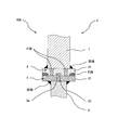
- the position where a rotary tool (not shown) is pressed is not limited to the upper surface of the groove forming member 41 and may be both side surfaces. Thereby, the joint strength of the part which protruded in the both sides with respect to the tank side support member 7 and the hull side support member 6 among the groove
- FIG. 10 shows a dissimilar joint structure 40B according to a second modification of the second embodiment.
- the outer shape of the groove forming member 46 and the insertion member 47 constituting the dissimilar joint structure 40B is the same as the outer shape of the groove forming member 41 and the insertion member 47 of the dissimilar joint structure 40 (see FIG. 8) having the above configuration.
- Two insertion grooves 8 a and 8 a are formed on the lower end surface of the groove forming member 46.
- Two convex portions 48 are formed on the upper end surface of the insertion member 47, and the convex portions 48 form insertion portions 9 and 9 that can be inserted into the corresponding insertion grooves 8a.
- the insertion member 47 is formed in each insertion groove 8a formed in the groove forming member 46.
- the insertion portion 9 is inserted, and the groove forming member 46 is assembled to the insertion member 47.
- a rotary tool (not shown) of the friction stir welding apparatus is pressed against the upper end surface of the groove forming member 46 to enter the insertion member 47 side. Further, the rotary tool is moved along the longitudinal direction. In the present modification, the position where the rotary tool is pressed is the upper end surface of the groove forming member 46 and two positions corresponding to the insertion groove 8a.
- the joint portions are in a complicatedly overlapping state. This further improves the fatigue strength of the dissimilar joint structure.
- the surface treatment of the insertion groove 8a and / or the insertion portion 9, the surface treatment of the lower end surface of the groove forming member 46 and / or the upper end surface of the insertion member 47, the corner processing of the corner portion of the insertion groove 8a, insertion By performing the chamfering of the portion 9 and the rust prevention treatment of the surfaces of the insertion groove 8a and the insertion portion 9 as appropriate, the same effects as the first embodiment can be obtained.
- FIG. 11 shows a dissimilar joint structure 40C according to a third modification of the second embodiment.
- the same parts as the dissimilar joint structure 40B (see FIG. 10) of the second modification are used.
- the position where a rotary tool (not shown) is pressed is not limited to the upper end surface of the groove forming member 46 but may be both side surfaces. Thereby, the joining strength of the part which protruded in the both sides with respect to the tank side support member 7 and the hull side support member 6 among the groove
- FIG. 12 shows a dissimilar joint structure 40D according to a fourth modification of the second embodiment.
- the same parts as the dissimilar joint structure 40B (see FIG. 10) of the second modification are used.
- the position where the rotary tool (not shown) is pressed is not limited to the two positions corresponding to the insertion groove 8 a on the upper end surface of the groove forming member 46, and is not limited to the two positions corresponding to the insertion groove 8 a. There may be a total of three positions between each other and the outside of these two positions.
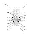
- FIG. 13 shows a dissimilar joint structure 50 according to the second embodiment.
- the dissimilar joint structure 50 includes a groove forming portion 8 formed as a separate body from the tank side support member 7 and an insertion portion 9 formed in the hull side support member 6.
- the groove forming portion 8 is constituted by a groove forming member 51.
- the groove forming member 51 is separate from the tank side support member 7, but is formed of the same metal material as the tank side support member 7, such as an Al—Mn alloy.
- the groove forming member 51 is formed in a flat plate shape, and the width of the groove forming member 51 is longer than the thickness of the tank side support member 7.
- the joint part of both members 7 and 51 is fillet welded. Since both members 7 and 51 are made of the same metal material, this welding can be easily performed.
- a single insertion groove 8 a extending in the longitudinal direction, that is, the circumferential direction of the tank-side support member 7 is formed on the lower end surface of the groove forming member 51.
- the insertion groove 8 a is formed in a size that allows insertion of the upper end portion of the hull supporting member 6 that functions as the insertion portion 9.
- the insertion portion 9 is formed at the upper end of the hull supporting member 6.
- a concave groove 52 extending in the longitudinal direction, that is, the circumferential direction of the hull supporting member 6 is formed on each side surface of the insertion portion 9. As illustrated, only one concave groove 52 may be formed, or a plurality of concave grooves may be formed on each side surface.
- the upper end of the hull supporting member 6 is inserted into the insertion groove 8a formed in the groove forming member 51.
- Part, that is, the insertion part 9 is inserted.
- a rotary tool (not shown) of the friction stir welding apparatus is pressed against the side surface of the groove forming member 51.
- the position where the rotary tool is pressed is a position corresponding to the concave groove 52 on each side surface of the groove forming member 51.
- the rotary tool is inserted toward the insertion portion 9 side, and the rotary tool is further moved along the longitudinal direction.
- the joining portions are in an overlapping state, a dissimilar joint structure with high fatigue strength can be provided. Further, since the fluidized metal material forming the bonding member 51 enters the concave groove 52 to form the convex portion 53, a high bonding strength can be obtained due to the anchor effect.
- the insertion portion 9 is formed integrally with the hull side support member 6, the insertion portion 9 is separated from the hull side support member 6 as in the first and second embodiments. Compared with the case where it comprises by, it is advantageous at the point which can omit welding operation.
- FIG. 14 shows a dissimilar joint structure 50A according to a first modification of the third embodiment.
- the same parts as the dissimilar joint structure 50 (see FIG. 13) having the above-described configuration are used.
- the position for pressing a rotation tool (not shown) is not limited to each side surface of the groove forming member 51, and may be a position corresponding to the insertion portion 9 on the upper end surface of the groove forming member 51. . Thereby, the joint strength between the groove forming member 51 and the insertion portion 9 can be further increased.
- FIG. 15 shows a dissimilar joint structure 50B according to a second modification of the third embodiment.
- the outer shape of the groove forming member 56 constituting the dissimilar joint structure 50B is the same as the outer shape of the groove forming member 51 of the dissimilar joint structure 50 (see FIG. 13) configured as described above.
- On the lower end surface of the groove forming member 56 a convex portion 57 is formed that protrudes from the surface of the insertion groove 8a toward the opening side of the insertion groove 8a.
- a concave portion 58 that can be fitted to the convex portion 57 is formed on the upper end surface of the insertion portion 9.
- the insertion part 9 is formed in the upper end part of the hull side support member 6 similarly to the dissimilar joint structure 50 (refer FIG. 13) of the said structure.
- the groove forming member 51 having the above structure is formed to form the insertion groove 8a and the insertion portion 9. And the hull supporting member 6 is manufactured.
- a convex portion 57 is formed on the groove forming member 56, and a concave groove 52 and a concave portion 58 are formed on the upper end portion of the hull supporting member 6.
- the insertion portion 9 formed on the hull supporting member 6 is inserted into the insertion groove 8 a formed on the groove forming member 56, and the groove forming member 56 is assembled to the upper end portion of the hull supporting member 6.
- the convex portion 57 is fitted into the concave portion 58.
- a rotary tool (not shown) of the friction stir welding apparatus is pressed against the upper end surface of the groove forming member 56 to enter the insertion portion 9 side. Further, the rotary tool is moved along the longitudinal direction. In this modification, the position where the rotary tool is pressed is on each side surface of the groove forming member 56 and corresponds to the concave groove 52, and between the upper end surface of the groove forming member 56 and the portion corresponding to the concave portion 52. There are a total of four places with the two positions.
- FIG. 16 shows a dissimilar joint structure 50C according to a third modification of the third embodiment.
- the same parts as the dissimilar joint structure 50B (see FIG. 15) configured as described above are used.
- the position at which the rotary tool (not shown) is pressed is the sum of the position corresponding to the concave groove 52 on each side surface of the groove forming member 56 and the position corresponding to the concave portion 58 on the upper end surface of the groove forming member 56. There are three places. Also with this configuration, it is possible to provide the dissimilar joint structure 50C having high bonding strength.
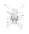
- FIG. 17 shows the dissimilar joint structure of the fourth embodiment.
- the dissimilar joint structure 60 includes a groove forming portion 8 formed separately from the tank side support member 7 and an insertion portion 9 formed in the hull side support member 6.
- the groove forming portion 8 of the dissimilar joint structure 60 includes a first groove forming member 61 and a second groove forming member 62.
- Each of the first and second groove forming members 61 and 62 has an L-shaped cross section.
- the first groove forming member 61 has a base portion 63 and a side wall portion 64 extending perpendicularly to the base portion 63, and the second groove forming member 62 is similarly configured with the base portion 65 and the side wall portion. 66.
- the thicknesses of the side wall portion 64 of the first groove forming member 61 and the side wall portion 65 of the second groove forming member 62 may be equal to each other in order to achieve common parts, or the side walls disposed on the inside as described above. You may form so that the thickness of the part 64 may be made thin compared with the thickness of the side wall part 66 arrange
- the insertion portion 9 is formed at the upper end of the hull supporting member 6, and a concave groove 67 extending in the longitudinal direction is formed on each side surface of the insertion portion 9.
- the inner surface of the insertion portion 9 is covered with the first groove forming member 61.
- the upper end surface of the insertion portion 9 is brought into contact with the inner surface of the base portion 63 of the first groove forming member 61.
- a rotary tool (not shown) of the friction stir welding apparatus is pressed against the outer surface of the first groove forming member 61.
- the position where the rotary tool is pressed is a position corresponding to each concave groove 67 on the outer surface of the side wall portion 64 of the first groove forming member 61.
- the rotary tool is inserted toward the insertion portion 9 side, and the rotary tool is further moved along the longitudinal direction.
- the first groove forming member 61 is joined to the inner surface of the insertion portion 9.
- the metal material forming the fluidized first groove forming member 61 penetrates into the concave groove 67 formed in the insertion portion 9 to every corner. Therefore, the first groove forming member 61 is formed with a convex portion 68 protruding into the concave groove 67, and the first groove forming member 61 is firmly joined to the insertion portion 9 by the anchor effect.
- the outer surface of the insertion portion 9 is covered with the second groove forming member 62.
- the upper end surface of the insertion portion 9 is brought into contact with the inner surface of the base portion 65 of the second groove forming member 62.
- the second groove forming member 62 is joined to the insertion portion 9 in the same manner as the first groove forming member 61.
- the side surfaces of the insertion portion 9 are covered with the first and second groove forming members 61 and 62, and the insertion portion 9 is inserted inside the first and second groove forming members 61 and 62. It will be in the state inserted in the groove
- the lower end portion of the tank side support member 7 is welded to the base portions 63 and 65 of the first and second groove forming members 61 and 62. Since the thickness of the tank side support member 7 is smaller than the distance from the end of one base part to the end of the other base part, each base part protrudes from the tank side support member. Fillet welding is performed at the protruding portion. Since the tank side support member 7 and the first and second groove forming members 61 and 62 are made of the same kind of metal, this welding can be easily performed.
- the insertion portion 9 is formed integrally with the hull side support member 6, the insertion portion 9 is separated from the hull side support member 6 as in the first and second embodiments. Compared with the case where it comprises by, it is advantageous at the point which can omit welding operation.
- the groove forming member has a half structure, and the insertion groove may not be formed in a single part. For this reason, compared with the 1st thru
- the first embodiment and the first embodiment are appropriately performed by rounding the corners formed by the inner surface of the inner surface, the chamfering of the insertion portion 9, the rust prevention treatment of the surface forming the insertion groove 8a, and the rust prevention treatment of the surface of the insertion portion 9. Similar effects can be obtained.
- FIG. 18 shows a dissimilar joint structure 70 according to the fifth embodiment.
- the dissimilar joint structure 70 includes a groove forming portion 8 formed by cooperation of the tank side support member 7 and a separate member of the tank side support member 7, and an insertion portion 9 formed on the hull side support member 6. And have.
- the groove forming portion 8 of the dissimilar joint structure 70 includes a lower end portion of the tank-side support member 7, a first groove forming member 71, and a second groove forming member 72.
- the tank-side support member 7 and the first and second groove forming members 71 and 72 are formed of the same kind of metal.
- Each of the first and second groove forming members 71 and 72 may have the same shape as each other in order to achieve common parts, and the first groove forming member constituting the inner side wall portion 13 as described above. You may form so that the thickness of 71 may be made thin compared with the thickness of the 2nd groove
- the inner surface of the first groove forming member 71 forms a curved surface having the same curvature as the inner surface of the hull-side support member 6 so as to cover the inner surface of the insertion portion 9 constituted by the end of the hull-side support member 6. Yes.
- the outer surface of the second groove forming member 72 forms a curved surface having the same curvature as the outer surface of the hull-side support member 6 so as to cover the outer surface of the insertion portion 9 constituted by the end of the hull-side support member 6. Yes.
- the first groove forming member 71 is formed so as to increase in thickness from the upper and lower central portions to the upper side, and the outer surface thereof is tapered. For this reason, the upper end part of the 1st groove
- a similar flange portion 74 is also formed at the upper end portion of the second groove forming member 72.
- the insertion portion 9 is constituted by the end portion of the hull supporting member 6 as described above, and a plurality of concave grooves 75 arranged in the vertical direction are formed on each side surface of the insertion portion 9.
- the inner surface of the insertion portion 9 is covered with the inner surface of the first groove forming member 71.
- the first groove forming member 71 is arranged such that the upper end surface 9a of the insertion portion 9 is flush with the upper end surface of the first groove forming member 71 (that is, the upper end surface of the flange portion 73) 73a. .
- a rotary tool (not shown) of the friction stir welding apparatus is pressed against the outer surface of the first groove forming member 71.
- the position which presses a rotation tool is a position (4 places in this embodiment) corresponding to each concave groove 75 in the side surface of the 1st groove
- FIG. The rotary tool is inserted toward the insertion portion 9 side, and the rotary tool is further moved along the longitudinal direction.
- the first groove forming member 71 is joined to the inner surface of the insertion portion 9.
- the metal material forming the fluidized first groove forming member 71 penetrates into the concave groove 75 formed in the insertion portion 9 to every corner. For this reason, the convex part 76 which protrudes in the concave groove 75 is formed in the 1st groove formation member 71, and the 1st groove formation member 71 is firmly joined to an insertion part by the anchor effect.
- the outer surface of the insertion portion 9 is covered with the inner surface of the second groove forming member 72.
- the second groove forming member 72 is arranged so that the upper end surface 9a of the insertion portion 9 is flush with the upper end surface of the second groove forming member 72 (that is, the upper end surface of the flange portion 74) 74a.
- a rotary tool (not shown) of the friction stir welding apparatus is pressed against the outer surface of the second groove forming member 72, and the second groove forming member 72 is bonded to the outer surface of the insertion portion 9 in the same manner as described above. .
- the metal material forming the fluidized second groove forming member 72 penetrates into the concave groove 75 formed in the insertion portion 9 to every corner. For this reason, the convex part 76 which protrudes in the concave groove 75 is formed in the 2nd groove formation member 72, and the 2nd groove formation member 72 is firmly joined to the insertion part 9 by the anchor effect.
- both side corners of the lower end portion of the tank side support member 7 are welded to the upper end portions of the first and second groove forming members 71, 72.
- the thickness of the tank side support member 7 is larger than the thickness of the hull side support member 6 that integrally forms the insertion portion 9
- the upper end portions of the first and second groove forming members 71 and 72 are the inner side surfaces, respectively. Since the flange portions 73 and 74 projecting to the opposite side of the tank side support member 7 are provided on the upper side of the first and second groove forming members 71 and 72, these flange portions 73 and 74 are provided.
- the parts 73 and 74 are in a state of projecting on both sides with respect to the tank side support member 7. Fillet welding is easily performed at the protruding portion. Further, since the tank side support member 7 and the first and second groove forming members 71 and 72 are made of the same kind of metal, this welding can be easily performed.
- the insertion portion 9 is connected to the lower end surface of the tank side support member 7, the first and second groove forming members 71, 72 is formed in the same shape as inserted into the insertion groove 8a formed by each inner side surface. Therefore, also in the present embodiment, the joined portions are overlapped, and a dissimilar joint structure with high fatigue strength is obtained.
- the upper end surface 9a of the insertion portion 9 is flush with the upper end surfaces 73a and 74a of the first and second groove forming members 71 and 72, and the lower end portion of the tank side support member 7 is the second end portion.
- fillet welding is performed in a state where the lower end surface 7 a of the tank side support member 7 is securely in contact with the upper end surface 9 a of the insertion portion 9.
- the load transmitted from the tank 3 through the tank side support member 7 is supported by the hull side support member 6 forming the insertion portion 9.
- channel formation members 71 and 72 can be raised.
- FIG. 19 shows a dissimilar joint structure 80 according to the sixth embodiment.
- This dissimilar joint structure 80 includes a groove forming portion 8 formed in the tank side support member 7 and an insertion portion 9 formed in the hull side support member 6.
- the groove forming portion 8 is formed at the lower end portion of the tank side support member 7.
- An insertion groove 8 a that is recessed upward is formed in the lower end surface of the tank side support member 7.
- the insertion groove 8a extends in the longitudinal direction, that is, in the circumferential direction of the tank side support member.
- the insertion groove 8 a is formed in a size that allows insertion of the upper end portion of the hull supporting member 6 that functions as the insertion portion 9.
- the insertion portion 9 is formed at the upper end of the hull supporting member 6.
- a concave groove 81 extending in the longitudinal direction, that is, the circumferential direction of the hull supporting member 6 is formed on each side surface of the insertion portion 9. As illustrated, only one concave groove 81 may be formed, or a plurality of concave grooves may be formed on each side surface.
- the groove forming portion 8 and the insertion into each of the tank side support member 7 and the hull side support member are inserted.
- the portion 9 is formed, the insertion portion 9 is inserted into the insertion groove 8a, and the tank side support member 7 and the hull side support member 6 are assembled.
- a rotary tool (not shown) of the friction stir welding apparatus is pressed against the side surface of the groove forming portion 8 to enter the insertion portion 9 side. Further, the rotary tool is moved along the longitudinal direction.
- the position where the rotary tool is pressed is a position corresponding to the concave groove 81 on the side surface of the groove forming portion 8.
- the groove forming portion 8 is formed integrally with the tank side support member 7 and the insertion portion 9 is formed integrally with the hull side support member 6, as in the first and second embodiments.
- the groove forming portion 8 is constituted by a member separate from the tank side support member 7 and the insertion portion 9 is constituted by a member separate from the hull side support member 6, it is advantageous in that the welding work can be omitted. is there.
- the material forming the tank side support member, the material forming the hull side support member, the material forming the groove forming portion, and the material forming the insertion portion are merely examples, and can be appropriately changed.
- the manufacturing cost can be reduced, ensuring the intensity
- the present invention is suitably applied when two members made of different metals are connected to each other. Although it can be particularly suitably applied to a tank skirt provided in an LNG transport ship, it can also be suitably applied to a dissimilar joint structure such as a transport machine, a machine part, or a building structural member for automobiles, railway vehicles, and the like.
Landscapes
- Engineering & Computer Science (AREA)
- Mechanical Engineering (AREA)
- General Engineering & Computer Science (AREA)
- Chemical & Material Sciences (AREA)
- Combustion & Propulsion (AREA)
- Ocean & Marine Engineering (AREA)
- Physics & Mathematics (AREA)
- Thermal Sciences (AREA)
- Pressure Welding/Diffusion-Bonding (AREA)
- Connection Of Plates (AREA)
Abstract
Description
1 LNG輸送船
2 船体
3 タンク
4 タンク用スカート
6 船体側支持部材(第2金属部材)
7 タンク側支持部材(第1金属部材)
8 溝形成部
8a 挿入溝
9 挿入部
10,10A 異材継手構造(第1実施形態)
40,40A,40B,40C,40D 異材継手構造(第2実施形態)
50,50A,50B,50C 異材継手構造(第3実施形態)
60 異材継手構造(第4実施形態)
70 異材継手構造(第5実施形態)
80 異材継手構造(第6実施形態)
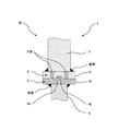
図4は本発明の第1実施形態に係る異材継手構造10の分解斜視図である。この異材継手構造10は、タンク側支持部材7とは別体として形成された溝形成部8と、船体側支持部材6とは別体として形成された挿入部9とを有している。
図8は第2実施形態の異材継手構造40を示している。本実施形態のうち上記の構成と共通する構成については同一の符号を付して詳細な説明を省略する。この異材継手構造40は、タンク側支持部材7とは別体のものとして形成される溝形成部8と、船体側支持部材6とは別体のものとして形成される挿入部9とを有している。
図13は第2実施形態の異材継手構造50を示している。本実施形態のうち上記の構成と共通する構成については同一の符号を付して詳細な説明を省略する。この異材継手構造50は、タンク側支持部材7とは別体のものとして形成される溝形成部8と、船体側支持部材6に形成された挿入部9とを有している。
図17は第4実施形態の異材継手構造を示している。本実施形態のうち上記の構成と共通する構成については同一の符号を付して詳細な説明を省略する。この異材継手構造60は、タンク側支持部材7と別体として形成される溝形成部8と、船体側支持部材6に形成される挿入部9とを有している。
図18は第5実施形態の異材継手構造70を示している。本実施形態のうち上記の構成と共通する構成については同一の符号を付して詳細な説明を省略する。この異材継手構造70は、タンク側支持部材7及びタンク側支持部材7の別体の部材とが協働して形成される溝形成部8と、船体側支持部材6に形成される挿入部9とを有している。
図19は第6実施形態の異材継手構造80を示している。本実施形態のうち上記の構成と共通する構成については同一の符号を付して詳細な説明を省略する。この異材継手構造80は、タンク側支持部材7に形成される溝形成部8と、船体側支持部材6に形成される挿入部9とを有している。
Claims (18)
- 互いに異種金属からなる第1金属部材及び第2金属部材を接合するための異材継手構造であって、
前記第1金属部材に挿入溝が形成され、前記第2金属部材に前記挿入溝内に挿入可能な挿入部が形成され、
前記挿入溝内に前記挿入部が挿入された状態で前記第1金属部材が前記第2金属部材と接合されることを特徴とする異材継手構造。 - 前記第1金属部材は、基部材と、該基部材と同種金属からなり前記挿入溝を区画する一対の側壁部をなす溝形成部材とを備えることを特徴とする請求項1に記載の異材継手構造。
- 前記溝形成部材が、前記挿入部の一側面を覆う第1溝形成部材と、前記挿入部の他側面を覆う第2溝形成部材とを備えることを特徴とする請求項2に記載の異材継手構造。
- 前記第1及び第2溝形成部材の各端面が、前記基部材の端面と接合されており、
前記挿入溝が、前記第1及び第2溝形成部材の内側面と、前記基部材の端面とにより形成されていることを特徴とする請求項3に記載の異材継手構造。 - 前記第1金属部材が、摩擦攪拌接合又は圧延接合によって前記挿入部と接合されることを特徴とする請求項1乃至4のいずれか1項に記載の異材継手構造。
- 前記挿入部の表面に凹溝が形成され、前記第1金属部材に前記凹溝内に突出する凸部が形成されていることを特徴とする請求項1乃至5のいずれか1項に記載の異材継手構造。
- 前記第1金属部材と前記第2金属部材との境界部分が水分の浸入を防止する被覆材で覆われていることを特徴とする請求項1乃至6のいずれか1項に記載の異材継手構造。
- 前記挿入溝を区画する一対の側壁部の厚さが、互いに異なることを特徴とする請求項1乃至7のいずれか1項に記載の異材継手構造。
- 前記第1金属部材がアルミニウム合金からなり、前記第2金属部材がステンレス鋼又は高マンガン鋼からなることを特徴とする請求項1乃至8のいずれか1項に記載の異材継手構造。
- 互いに異種金属からなる第1金属部材及び第2金属部材を接合する方法であって、
前記第1金属部材に形成された挿入溝溝内に前記第2金属部材に形成された挿入部を挿入する工程と、
前記第1金属部材の外面に摩擦攪拌接合装置の回転ツールを押し当て、該回転ツールを該外面から前記挿入部側へ侵入させ、前記回転ツールを前記第1金属部材の延在方向に移動させることにより、前記第1金属部材を前記第2金属部材に接合する工程と、
を有することを特徴とする異種金属部材の接合方法。 - 前記挿入部を挿入する工程の前に、更に、前記挿入部の表面に凹溝を形成する工程を有し、
前記第1金属部材を前記第2金属部材に接合する工程において、摩擦攪拌により流動化した前記第1金属部材をなす金属材料が前記凹溝内に侵入することを特徴とする請求項10に記載の異種金属部材の接合方法。 - 前記挿入部を挿入する工程の前に、更に、前記挿入溝及び/又は前記挿入部の表面に生成されている酸化皮膜を除去する工程を有することを特徴とする請求項10又は11に記載の異種金属部材の異種金属部材の接合方法。
- 前記挿入部を挿入する工程の前に、更に、前記挿入溝の表面及び/又は前記挿入部の表面の面粗度を小さくする工程を有することを特徴とする請求項10乃至12のいずれか1項に記載の異種金属部材の接合方法。
- 前記挿入部を挿入する工程の前に、更に、前記挿入溝及び/又は前記挿入部の表面に防錆皮膜を生成する工程を有し、
前記第1金属部材を前記挿入部に接合する工程で、前記回転ツールの作用により前記防錆皮膜を剥がすことを特徴とする請求項10乃至13のいずれか1項に記載の異種金属部材の接合方法。 - 互いに異種金属からなる第1金属部材及び第2金属部材を接合するための異種金属部材の接合方法であって、
前記第2金属部材に形成された挿入部の一側面を第1溝形成部材で覆う工程と、
前記第1溝形成部材の外面に摩擦攪拌接合装置の回転ツールを押し当て、該回転ツールを該外面から前記挿入部側へ侵入させ、前記回転ツールを前記第1溝形成部材の延在方向に移動させることにより、前記第1溝形成部材を前記挿入部に接合する工程と、
前記挿入部の他側面を第2溝形成部材で覆う工程と、
前記第2溝形成部材の外面に摩擦攪拌接合装置の回転ツールを押し当て、該回転ツールを該外面から前記挿入部側へ侵入させ、前記回転ツールを前記第2溝形成部材の延在方向に移動させることにより、前記第1溝形成部材を前記挿入部に接合する工程と、
前記第1金属部材の端面を前記挿入部の端面に当接した状態として、前記第1金属部材の端面を前記第1溝形成部材及び前記第2溝形成部材の各端面に接合する工程と
を有することを特徴とする異種金属部材の接合方法。 - 船体に固定されてタンクを支持するタンク用スカートであって、
前記タンクに固定されるタンク側支持部材と、
前記船体に固定されて前記タンク側支持部材と異種金属からなる船体側支持部材と、
前記タンク側支持部材と前記船体側支持部材とを接合するための異材継手構造とを備え、
前記タンク側支持部材及び前記船体側支持部材のうちの一方に前記異材継手構造を構成する挿入溝が形成され、前記タンク側支持部材及び前記船体側支持部材のうちの他方に前記挿入溝内に挿入可能な前記異材継手構造を構成する挿入部が形成され、
前記挿入溝内に前記挿入部が挿入された状態で前記タンク側支持部材が前記船体側支持部材と接合されることを特徴とするタンク用スカート。 - 前記タンク側支持部材に前記挿入溝が形成され、
前記タンク側支持部材は、前記挿入溝を区画して前記挿入部における前記タンクが設けられている側の側面を覆う内側の側壁部と、その反対側の側面を覆う外側の側壁部とを有し、前記内側の側壁部の厚さが、前記外側の側壁部の厚さよりも薄いことを特徴とする請求項14に記載のタンク用スカート。 - 船体と、前記船体に搭載されたタンクと、前記船体に固定されて前記タンクを支持するタンク用スカートとを備え、
該タンク用スカートが、前記タンクに固定されるタンク側支持部材と、前記船体に固定されて前記タンク側支持部材と異種金属からなる船体側支持部材と、前記タンク側支持部材と前記船体側支持部材とを接合するための異材継手構造とを備え、
前記タンク側支持部材及び前記船体側支持部材のうちの一方に前記異材継手構造を構成する挿入溝が形成され、前記タンク側支持部材及び前記船体側支持部材のうちの他方に前記挿入溝内に挿入可能な前記異材継手構造を構成する挿入部が形成され、
前記挿入溝内に前記挿入部が挿入された状態で前記タンク側支持部材が前記船体側支持部材と接合されることを特徴とする輸送船。
Priority Applications (4)
| Application Number | Priority Date | Filing Date | Title |
|---|---|---|---|
| JP2009547871A JP5204788B2 (ja) | 2007-12-27 | 2008-09-17 | 異材継手構造、該異材継手構造を備えるタンク用スカート、該タンク用スカートを備える輸送船、及び異種金属部材の接合方法 |
| US12/810,504 US8113133B2 (en) | 2007-12-27 | 2008-09-17 | Dissimilar joint structure, tank skirt including dissimilar joint structure, transport ship including tank skirt, and method for joining dissimilar metal members |
| EP08867990.7A EP2236841A4 (en) | 2007-12-27 | 2008-09-17 | UNEVEN METAL CONNECTION STRUCTURE, BOARD WITH THE UNBELIEVABLE METAL CONNECTION STRUCTURE, CARRIAGE TO THE BOARD AND METHOD FOR CONNECTING UNEVEN METAL ELEMENTS |
| CN2008801231379A CN101910649B (zh) | 2007-12-27 | 2008-09-17 | 相异材料接头结构、具备该相异材料接头结构的容器用的裙边、具备该容器用的裙边的运输船、以及不同种类金属构件的接合方法 |
Applications Claiming Priority (2)
| Application Number | Priority Date | Filing Date | Title |
|---|---|---|---|
| JP2007-336311 | 2007-12-27 | ||
| JP2007336311 | 2007-12-27 |
Publications (1)
| Publication Number | Publication Date |
|---|---|
| WO2009084136A1 true WO2009084136A1 (ja) | 2009-07-09 |
Family
ID=40823874
Family Applications (1)
| Application Number | Title | Priority Date | Filing Date |
|---|---|---|---|
| PCT/JP2008/002556 Ceased WO2009084136A1 (ja) | 2007-12-27 | 2008-09-17 | 異材継手構造、該異材継手構造を備えるタンク用スカート、該タンク用スカートを備える輸送船、及び異種金属部材の接合方法 |
Country Status (6)
| Country | Link |
|---|---|
| US (1) | US8113133B2 (ja) |
| EP (1) | EP2236841A4 (ja) |
| JP (1) | JP5204788B2 (ja) |
| KR (1) | KR101209971B1 (ja) |
| CN (1) | CN101910649B (ja) |
| WO (1) | WO2009084136A1 (ja) |
Cited By (10)
| Publication number | Priority date | Publication date | Assignee | Title |
|---|---|---|---|---|
| AT509651B1 (de) * | 2010-04-12 | 2012-09-15 | Voestalpine Stahl Gmbh | Verfahren zum stoffschlüssigen fügen |
| WO2013076764A1 (ja) * | 2011-11-22 | 2013-05-30 | 川崎重工業株式会社 | 異材継手、タンク支持部材及びlng船、並びに異材継手の製造方法 |
| JP2015116609A (ja) * | 2013-11-12 | 2015-06-25 | 株式会社エフテック | 摩擦撹拌接合部材及びその製造方法 |
| WO2016013439A1 (ja) * | 2014-07-24 | 2016-01-28 | 三井造船株式会社 | 液化ガス輸送船、及び、液化ガス輸送船の設計方法 |
| JP2016182878A (ja) * | 2015-03-26 | 2016-10-20 | 三菱重工業株式会社 | タンクの支持構造及び船舶 |
| JP6188101B1 (ja) * | 2016-09-12 | 2017-08-30 | 株式会社沖新船舶工業 | 異種金属嵌合継手 |
| KR101784851B1 (ko) * | 2016-02-18 | 2017-11-06 | 삼성중공업 주식회사 | 해양구조물에 구비된 저장탱크의 설치방법 |
| KR20170130536A (ko) | 2015-04-08 | 2017-11-28 | 카와사키 주코교 카부시키 카이샤 | 선박용 액화가스 탱크 및 그것을 구비하는 액화가스 운반선 |
| KR20180048966A (ko) | 2015-10-05 | 2018-05-10 | 카와사키 주코교 카부시키 카이샤 | 선박용 액화가스 탱크 및 그것을 구비하는 액화가스 운반선 |
| JP7527107B2 (ja) | 2019-12-27 | 2024-08-02 | 三菱造船株式会社 | カーゴタンクユニット及び船舶 |
Families Citing this family (8)
| Publication number | Priority date | Publication date | Assignee | Title |
|---|---|---|---|---|
| US8561877B2 (en) * | 2011-10-27 | 2013-10-22 | GM Global Technology Operations LLC | Structural integrity welded assembly |
| FR3010338B1 (fr) * | 2013-09-06 | 2016-01-22 | Sominex | Procede de soudage par friction malaxage par transparence de deux materiaux metalliques ou d'alliages metalliques differents |
| FR3013305B1 (fr) * | 2013-11-21 | 2015-11-20 | Nexter Systems | Structure de caisse de vehicule et procede d'assemblage d'une telle structure |
| KR101960556B1 (ko) * | 2014-10-21 | 2019-03-20 | 현대중공업 주식회사 | 액화천연가스 저장장치 |
| CN105414738B (zh) * | 2015-12-30 | 2018-01-30 | 哈尔滨工业大学 | 一种环形槽辅助强化管板摩擦形变扩散焊接方法 |
| US10895276B2 (en) * | 2018-02-20 | 2021-01-19 | Dana Automotive Systems Group, Llc | Two material joint design |
| JPWO2021106311A1 (ja) * | 2019-11-29 | 2021-06-03 | ||
| CN116352235B (zh) * | 2023-03-06 | 2025-12-16 | 南京钢铁股份有限公司 | 高锰钢与316l异种钢的焊接方法 |
Citations (6)
| Publication number | Priority date | Publication date | Assignee | Title |
|---|---|---|---|---|
| JPH11342481A (ja) * | 1998-06-01 | 1999-12-14 | Nippon Light Metal Co Ltd | 厚肉の被接合材の摩擦撹拌接合方法及び接合構造並びにこれを用いたクレーンブーム |
| JP2001259865A (ja) * | 2000-03-16 | 2001-09-25 | Yamashita Rubber Co Ltd | 金属製部材の結合方法 |
| JP2004074870A (ja) * | 2002-08-13 | 2004-03-11 | Mitsubishi Heavy Ind Ltd | 異材継手 |
| JP2005007466A (ja) * | 2003-06-20 | 2005-01-13 | Mitsubishi Heavy Ind Ltd | 摩擦攪拌接合方法と、その装置及び該方法により製造された構造体 |
| JP2007153064A (ja) | 2005-12-02 | 2007-06-21 | Mitsubishi Heavy Ind Ltd | 液体運搬船、船舶 |
| JP2007222925A (ja) * | 2006-02-24 | 2007-09-06 | Mitsubishi Heavy Ind Ltd | 摩擦攪拌接合方法 |
Family Cites Families (9)
| Publication number | Priority date | Publication date | Assignee | Title |
|---|---|---|---|---|
| US4111146A (en) * | 1977-06-22 | 1978-09-05 | General Dynamics Corporation | Tank support joint |
| US4430954A (en) * | 1980-12-01 | 1984-02-14 | General Dynamics Corporation | Cargo tank support |
| JPS63247026A (ja) * | 1987-04-02 | 1988-10-13 | Sumitomo Electric Ind Ltd | 金属円筒と繊維強化プラスチツク円筒の継手構造 |
| JP3552154B2 (ja) * | 1998-01-12 | 2004-08-11 | 古河スカイ株式会社 | アルミニウム又はアルミニウム合金部材からなる密封体、並びに半導体製造装置又は薄型ディスプレー製造装置の基板ホルダー及びそれを製造する方法 |
| JP2003314782A (ja) * | 2002-04-23 | 2003-11-06 | Mitsubishi Heavy Ind Ltd | 配管接続部の補修方法、流体配管 |
| US6908690B2 (en) * | 2002-04-29 | 2005-06-21 | The Boeing Company | Method and apparatus for friction stir welding |
| JP2004106037A (ja) * | 2002-09-20 | 2004-04-08 | Hitachi Ltd | 金属材料の結合方法 |
| US7703654B2 (en) * | 2004-11-17 | 2010-04-27 | The Boeing Company | Counter-rotating spindle for friction stir welding |
| JP4555160B2 (ja) * | 2005-06-01 | 2010-09-29 | 株式会社神戸製鋼所 | アルミニウム材との異材溶接接合用鋼板および異材接合体 |
-
2008
- 2008-09-17 EP EP08867990.7A patent/EP2236841A4/en not_active Withdrawn
- 2008-09-17 US US12/810,504 patent/US8113133B2/en not_active Expired - Fee Related
- 2008-09-17 KR KR1020107012983A patent/KR101209971B1/ko not_active Expired - Fee Related
- 2008-09-17 WO PCT/JP2008/002556 patent/WO2009084136A1/ja not_active Ceased
- 2008-09-17 JP JP2009547871A patent/JP5204788B2/ja not_active Expired - Fee Related
- 2008-09-17 CN CN2008801231379A patent/CN101910649B/zh not_active Expired - Fee Related
Patent Citations (6)
| Publication number | Priority date | Publication date | Assignee | Title |
|---|---|---|---|---|
| JPH11342481A (ja) * | 1998-06-01 | 1999-12-14 | Nippon Light Metal Co Ltd | 厚肉の被接合材の摩擦撹拌接合方法及び接合構造並びにこれを用いたクレーンブーム |
| JP2001259865A (ja) * | 2000-03-16 | 2001-09-25 | Yamashita Rubber Co Ltd | 金属製部材の結合方法 |
| JP2004074870A (ja) * | 2002-08-13 | 2004-03-11 | Mitsubishi Heavy Ind Ltd | 異材継手 |
| JP2005007466A (ja) * | 2003-06-20 | 2005-01-13 | Mitsubishi Heavy Ind Ltd | 摩擦攪拌接合方法と、その装置及び該方法により製造された構造体 |
| JP2007153064A (ja) | 2005-12-02 | 2007-06-21 | Mitsubishi Heavy Ind Ltd | 液体運搬船、船舶 |
| JP2007222925A (ja) * | 2006-02-24 | 2007-09-06 | Mitsubishi Heavy Ind Ltd | 摩擦攪拌接合方法 |
Non-Patent Citations (1)
| Title |
|---|
| See also references of EP2236841A4 * |
Cited By (15)
| Publication number | Priority date | Publication date | Assignee | Title |
|---|---|---|---|---|
| AT509651B1 (de) * | 2010-04-12 | 2012-09-15 | Voestalpine Stahl Gmbh | Verfahren zum stoffschlüssigen fügen |
| WO2013076764A1 (ja) * | 2011-11-22 | 2013-05-30 | 川崎重工業株式会社 | 異材継手、タンク支持部材及びlng船、並びに異材継手の製造方法 |
| WO2013076884A1 (ja) * | 2011-11-22 | 2013-05-30 | 川崎重工業株式会社 | 異材継手、構造体支持部材及びlng船、並びに異材継手の製造方法 |
| KR20140084283A (ko) * | 2011-11-22 | 2014-07-04 | 카와사키 주코교 카부시키 카이샤 | 이재 조인트, 구조체 지지 부재, lng선 및 이재 조인트의 제조 방법 |
| KR101641629B1 (ko) | 2011-11-22 | 2016-07-21 | 카와사키 주코교 카부시키 카이샤 | 이재 조인트, 구조체 지지 부재, lng선 및 이재 조인트의 제조 방법 |
| JP2015116609A (ja) * | 2013-11-12 | 2015-06-25 | 株式会社エフテック | 摩擦撹拌接合部材及びその製造方法 |
| JP2016022931A (ja) * | 2014-07-24 | 2016-02-08 | 三井造船株式会社 | 液化ガス輸送船、及び、液化ガス輸送船の設計方法 |
| WO2016013439A1 (ja) * | 2014-07-24 | 2016-01-28 | 三井造船株式会社 | 液化ガス輸送船、及び、液化ガス輸送船の設計方法 |
| JP2016182878A (ja) * | 2015-03-26 | 2016-10-20 | 三菱重工業株式会社 | タンクの支持構造及び船舶 |
| KR20170130536A (ko) | 2015-04-08 | 2017-11-28 | 카와사키 주코교 카부시키 카이샤 | 선박용 액화가스 탱크 및 그것을 구비하는 액화가스 운반선 |
| KR20180048966A (ko) | 2015-10-05 | 2018-05-10 | 카와사키 주코교 카부시키 카이샤 | 선박용 액화가스 탱크 및 그것을 구비하는 액화가스 운반선 |
| KR101784851B1 (ko) * | 2016-02-18 | 2017-11-06 | 삼성중공업 주식회사 | 해양구조물에 구비된 저장탱크의 설치방법 |
| JP6188101B1 (ja) * | 2016-09-12 | 2017-08-30 | 株式会社沖新船舶工業 | 異種金属嵌合継手 |
| JP2018044553A (ja) * | 2016-09-12 | 2018-03-22 | 株式会社沖新船舶工業 | 異種金属嵌合継手 |
| JP7527107B2 (ja) | 2019-12-27 | 2024-08-02 | 三菱造船株式会社 | カーゴタンクユニット及び船舶 |
Also Published As
| Publication number | Publication date |
|---|---|
| EP2236841A8 (en) | 2010-11-17 |
| CN101910649A (zh) | 2010-12-08 |
| EP2236841A1 (en) | 2010-10-06 |
| KR101209971B1 (ko) | 2012-12-07 |
| JP5204788B2 (ja) | 2013-06-05 |
| EP2236841A4 (en) | 2016-01-27 |
| CN101910649B (zh) | 2013-02-27 |
| US20100275834A1 (en) | 2010-11-04 |
| US8113133B2 (en) | 2012-02-14 |
| KR20100087380A (ko) | 2010-08-04 |
| JPWO2009084136A1 (ja) | 2011-05-12 |
Similar Documents
| Publication | Publication Date | Title |
|---|---|---|
| JP5204788B2 (ja) | 異材継手構造、該異材継手構造を備えるタンク用スカート、該タンク用スカートを備える輸送船、及び異種金属部材の接合方法 | |
| CN105358285B (zh) | 摩擦搅拌接合方法 | |
| JP7003589B2 (ja) | 接合方法 | |
| KR101269807B1 (ko) | 접합 방법 | |
| JP6052237B2 (ja) | 摩擦攪拌接合方法 | |
| JPWO2007119343A1 (ja) | 摩擦攪拌接合用工具および摩擦攪拌接合方法 | |
| WO2013076764A1 (ja) | 異材継手、タンク支持部材及びlng船、並びに異材継手の製造方法 | |
| US7766214B2 (en) | Friction stir welding method | |
| JPH1128581A (ja) | 摩擦撹拌接合による継手の形成方法 | |
| JP4413677B2 (ja) | 異種金属部材の点接合方法 | |
| JP2007245198A (ja) | 材料の接合方法 | |
| JP4450728B2 (ja) | 摩擦撹拌接合方法 | |
| JP2007209986A (ja) | 摩擦攪拌接合方法 | |
| JP4453506B2 (ja) | 摩擦点接合方法 | |
| JP2006192501A (ja) | 重ね継手の形成方法、圧延用板の接合方法、板材へのリブ材接合方法および中空体の製造方法 | |
| JP2007301578A (ja) | 材料の接合方法 | |
| JP6756215B2 (ja) | 接合方法 | |
| JP6688755B2 (ja) | 金属薄板の接合方法及び金属薄板の接合構造 | |
| JP2009279595A (ja) | 接合方法 | |
| JP2008194732A (ja) | 接合方法 | |
| JP2020097046A (ja) | 接合方法 | |
| JP2018020345A (ja) | 摩擦攪拌接合方法 | |
| JP2005103574A (ja) | パネル接合構造 | |
| JP2005329453A (ja) | 摩擦撹拌接合方法 | |
| JP2020185605A (ja) | 中空容器の製造方法 |
Legal Events
| Date | Code | Title | Description |
|---|---|---|---|
| WWE | Wipo information: entry into national phase |
Ref document number: 200880123137.9 Country of ref document: CN |
|
| 121 | Ep: the epo has been informed by wipo that ep was designated in this application |
Ref document number: 08867990 Country of ref document: EP Kind code of ref document: A1 |
|
| DPE1 | Request for preliminary examination filed after expiration of 19th month from priority date (pct application filed from 20040101) | ||
| ENP | Entry into the national phase |
Ref document number: 20107012983 Country of ref document: KR Kind code of ref document: A |
|
| ENP | Entry into the national phase |
Ref document number: 2009547871 Country of ref document: JP Kind code of ref document: A |
|
| NENP | Non-entry into the national phase |
Ref country code: DE |
|
| WWE | Wipo information: entry into national phase |
Ref document number: 2008867990 Country of ref document: EP |
|
| WWE | Wipo information: entry into national phase |
Ref document number: 12810504 Country of ref document: US |