WO2009087788A1 - 舶用ディーゼル機関 - Google Patents
舶用ディーゼル機関 Download PDFInfo
- Publication number
- WO2009087788A1 WO2009087788A1 PCT/JP2008/063656 JP2008063656W WO2009087788A1 WO 2009087788 A1 WO2009087788 A1 WO 2009087788A1 JP 2008063656 W JP2008063656 W JP 2008063656W WO 2009087788 A1 WO2009087788 A1 WO 2009087788A1
- Authority
- WO
- WIPO (PCT)
- Prior art keywords
- exhaust
- turbine
- supercharger
- air supply
- air
- Prior art date
- Legal status (The legal status is an assumption and is not a legal conclusion. Google has not performed a legal analysis and makes no representation as to the accuracy of the status listed.)
- Ceased
Links
Images

Classifications
-
- F—MECHANICAL ENGINEERING; LIGHTING; HEATING; WEAPONS; BLASTING
- F02—COMBUSTION ENGINES; HOT-GAS OR COMBUSTION-PRODUCT ENGINE PLANTS
- F02B—INTERNAL-COMBUSTION PISTON ENGINES; COMBUSTION ENGINES IN GENERAL
- F02B37/00—Engines characterised by provision of pumps driven at least for part of the time by exhaust
- F02B37/007—Engines characterised by provision of pumps driven at least for part of the time by exhaust with exhaust-driven pumps arranged in parallel, e.g. at least one pump supplying alternatively
-
- F—MECHANICAL ENGINEERING; LIGHTING; HEATING; WEAPONS; BLASTING
- F02—COMBUSTION ENGINES; HOT-GAS OR COMBUSTION-PRODUCT ENGINE PLANTS
- F02B—INTERNAL-COMBUSTION PISTON ENGINES; COMBUSTION ENGINES IN GENERAL
- F02B37/00—Engines characterised by provision of pumps driven at least for part of the time by exhaust
- F02B37/001—Engines characterised by provision of pumps driven at least for part of the time by exhaust using exhaust drives arranged in parallel
- F02B37/002—Engines characterised by provision of pumps driven at least for part of the time by exhaust using exhaust drives arranged in parallel the exhaust supply to one of the exhaust drives can be interrupted
-
- F—MECHANICAL ENGINEERING; LIGHTING; HEATING; WEAPONS; BLASTING
- F02—COMBUSTION ENGINES; HOT-GAS OR COMBUSTION-PRODUCT ENGINE PLANTS
- F02B—INTERNAL-COMBUSTION PISTON ENGINES; COMBUSTION ENGINES IN GENERAL
- F02B37/00—Engines characterised by provision of pumps driven at least for part of the time by exhaust
- F02B37/12—Control of the pumps
- F02B37/16—Control of the pumps by bypassing charging air
-
- F—MECHANICAL ENGINEERING; LIGHTING; HEATING; WEAPONS; BLASTING
- F02—COMBUSTION ENGINES; HOT-GAS OR COMBUSTION-PRODUCT ENGINE PLANTS
- F02B—INTERNAL-COMBUSTION PISTON ENGINES; COMBUSTION ENGINES IN GENERAL
- F02B37/00—Engines characterised by provision of pumps driven at least for part of the time by exhaust
- F02B37/12—Control of the pumps
- F02B37/22—Control of the pumps by varying cross-section of exhaust passages or air passages, e.g. by throttling turbine inlets or outlets or by varying effective number of guide conduits
- F02B37/225—Control of the pumps by varying cross-section of exhaust passages or air passages, e.g. by throttling turbine inlets or outlets or by varying effective number of guide conduits air passages
-
- Y—GENERAL TAGGING OF NEW TECHNOLOGICAL DEVELOPMENTS; GENERAL TAGGING OF CROSS-SECTIONAL TECHNOLOGIES SPANNING OVER SEVERAL SECTIONS OF THE IPC; TECHNICAL SUBJECTS COVERED BY FORMER USPC CROSS-REFERENCE ART COLLECTIONS [XRACs] AND DIGESTS
- Y02—TECHNOLOGIES OR APPLICATIONS FOR MITIGATION OR ADAPTATION AGAINST CLIMATE CHANGE
- Y02T—CLIMATE CHANGE MITIGATION TECHNOLOGIES RELATED TO TRANSPORTATION
- Y02T10/00—Road transport of goods or passengers
- Y02T10/10—Internal combustion engine [ICE] based vehicles
- Y02T10/12—Improving ICE efficiencies
Definitions
- the present invention relates to a marine diesel engine, and more particularly to a marine diesel engine provided with a plurality of superchargers that increase the pressure of air supply using exhaust gas.
- the merchant ship may be operated at a somewhat reduced speed from the normal voyage speed. In such cases, it is necessary to operate the main engine with a load that is somewhat lower than the normal voyage load.
- the optimum supercharging can be achieved over a wide range of main engine loads. It is difficult to obtain efficiency. Therefore, by installing multiple turbochargers and controlling the number of operating units, optimum turbocharger efficiency can be obtained over a wide range of main engine loads. Compared to the case of using only one normal turbocharger. It is possible to reduce fuel consumption, and as a result, it is possible to contribute to improving the profitability of merchant vessels and reducing the environmental burden.
- a marine diesel engine provided with a plurality of such superchargers for example, one disclosed in Patent Document 1 is known. JP-A-60-166716
- the present invention has been made in view of the above circumstances, and in a marine diesel engine provided with a plurality of superchargers, when the supercharger is operated in parallel from a single operation or in a single operation from a parallel operation, always It is possible to prevent the reverse flow phenomenon from the compressor section of the turbocharger that is in operation to the compressor section of the turbocharger that is started or stopped, and to smoothly start or stop the turbocharger that is started or stopped.
- An object of the present invention is to provide a marine diesel engine that can prevent surging of a turbocharger that is started or stopped.
- a marine diesel engine according to the present invention includes an engine body, a turbine section driven by exhaust gas guided from the engine body, and a compressor section that is driven by the turbine section and pumps outside air to the engine body.
- At least one main exhaust turbine supercharger which is always in an operating state during operation of the engine body, a turbine section driven by exhaust gas guided from the engine body, and the turbine section At least one sub-exhaust that is driven by the engine and pumps outside air to the engine body, and is in a stopped state or a parallel operation state with the main exhaust turbine supercharger during operation of the engine body
- a marine diesel engine having a turbine supercharger, the exhaust manifold mounted on the engine body, An exhaust pipe communicating with the turbine section of the air turbine supercharger, a turbine inlet valve connected in the middle of the exhaust pipe, a compressor section of the auxiliary exhaust turbine supercharger, and an air supply mounted on the engine body
- An air supply pipe communicating with a manifold, and a check that is connected in the middle of the air supply pipe and that opens when the outlet pressure of the compressor section of the auxiliary exhaust turbine supercharger is equal to or higher than the pressure of the air supply manifold
- a valve an air discharge pipe having one end connected between the compressor portion of the auxiliary
- the marine diesel engine operating method includes a single engine body, a turbine section driven by exhaust gas introduced from the engine body, and the engine body driven by the outside air. At least one main exhaust turbine supercharger that is always in an operating state during operation of the engine main body, and a turbine unit driven by exhaust gas guided from the engine main body And a compressor unit that is driven by the turbine unit and pumps outside air to the engine body, and is stopped during operation of the engine body or is operated in parallel with the main exhaust turbine supercharger.
- At least one sub exhaust turbine supercharger, and an exhaust manifold mounted on the engine body An exhaust pipe communicating with the turbine section of the exhaust turbine supercharger, a turbine inlet valve connected in the middle of the exhaust pipe, a compressor section of the auxiliary exhaust turbine supercharger, and an air supply mounted on the engine body
- An air supply pipe that communicates with the manifold, and a check valve that is connected in the middle of the air supply pipe and that opens when the outlet pressure of the compressor section of the sub exhaust turbine supercharger is equal to or higher than the air supply manifold pressure
- an air discharge pipe having one end connected between the compressor part of the auxiliary exhaust turbine supercharger and the check valve in the middle of the air supply pipe, and air connected in the middle of the air discharge pipe
- a marine diesel engine operating method comprising a discharge valve, wherein when the auxiliary exhaust turbine supercharger is started, the air release valve is opened in advance, and then the turbine inlet valve is opened. Will close the air discharge valve gradually the when stopping the auxiliary exhaust gas turbine turbocharger, will
- the check valve provided in the air supply pipe starts, for example, the auxiliary exhaust turbine supercharger, and the auxiliary exhaust turbine overload.
- the outlet pressure of the compressor section of the feeder becomes equal to or higher than the pressure of the air supply manifold, it is opened (fully opened).
- the reverse flow phenomenon from the supply manifold to the compressor section of the sub exhaust turbine supercharger when the sub exhaust turbine supercharger is started and the sub exhaust turbine supercharger rotates smoothly (starts up). And the surging of the auxiliary exhaust turbine supercharger can be prevented.
- the check valve provided in the air supply pipe opens, for example, an air release valve, and a sub-exhaust turbine supercharger.
- the outlet pressure of the compressor section of the machine becomes lower than the pressure of the air supply manifold, it is closed (fully closed).
- the check valve provided in the air supply pipe opens, for example, an air release valve, and a sub-exhaust turbine supercharger.
- the turbocharger when the supercharger is operated in parallel from the single operation, or when the supercharger is operated independently from the parallel operation, the turbocharger is always started or stopped from the compressor unit of the supercharger in the operating state.
- the backflow phenomenon to the compressor part of the supercharger can be prevented, the supercharger that is started or stopped can be started or stopped smoothly, and surging of the supercharger that is started or stopped can be prevented. There is an effect that can be.
- FIG. 1 is a schematic configuration diagram of a marine diesel engine according to an embodiment of the present invention. It is a graph for demonstrating the effect of the marine diesel engine which concerns on this invention. It is a graph for demonstrating the effect of the marine diesel engine which concerns on this invention.
- FIG. 1 is a schematic configuration diagram of a marine diesel engine according to this embodiment
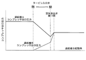
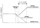
- FIG. 2 and FIG. 3 are graphs for explaining the operational effects of the marine diesel engine according to the present invention.
- a marine diesel engine 1 includes a diesel engine main body (for example, a low-speed two-cycle diesel engine) 2 and a first exhaust turbine supercharger (main exhaust turbine supercharger) 3. And a second exhaust turbine supercharger (sub-exhaust turbine supercharger) 4.
- a screw propeller (not shown) is directly or indirectly connected to a crankshaft (not shown) constituting the diesel engine main body (hereinafter referred to as “engine main body”) 2 via a propeller shaft (not shown). It is attached.
- the engine body 2 is provided with a cylinder portion 5 including a cylinder liner (not shown), a cylinder cover (not shown), and the like, and in each cylinder portion 5 is a piston connected to a crankshaft. (Not shown) is arranged.
- an exhaust port (not shown) of each cylinder portion 5 is connected to an exhaust manifold 6, and the exhaust manifold 6 is connected to a first exhaust turbine supercharger (hereinafter referred to as “the first exhaust turbine supercharger”) via a first exhaust pipe L 1. It is connected to the inlet side of the turbine section 3a of 3 and is connected to the second exhaust turbine supercharger (hereinafter referred to as “supercharger B”) via the second exhaust pipe L2.
- each cylinder portion 5 is connected to an air supply manifold 7, and the air supply manifold 7 is connected to the compressor portion 3b of the supercharger A3 via the first air supply pipe L3. And is connected to the compressor section 4b of the supercharger B4 via the second air supply pipe L4.
- the supercharger A3 is driven by exhaust gas (combustion gas) guided from the engine main body 2 via the first exhaust pipe L1, and is driven by the turbine part 3a so that the outside air is supplied to the engine main body 2.
- the main component is a compressor section 3b that pumps the air and a casing (not shown) that is provided between the turbine section 3a and the compressor section 3b and supports them.
- the casing is inserted with a rotating shaft 3c having one end projecting toward the turbine section 3a and the other end projecting toward the compressor section 3b.
- One end portion of the rotating shaft 3c is attached to a turbine disk (not shown) of a turbine rotor (not shown) constituting the turbine portion 3a, and the other end portion of the rotating shaft 3c is connected to the compressor portion 3b. It is attached to a hub (not shown) of a compressor impeller (not shown).
- the supercharger B4 is driven by exhaust gas (combustion gas) guided from the engine main body 2 via the second exhaust pipe L2, and is driven by the turbine part 4a so that the outside air is supplied to the engine main body 2.
- the main component is a compressor section 4b that pumps the air and a casing (not shown) that is provided between and supports the turbine section 4a and the compressor section 4b. Further, a rotating shaft 4c is inserted through the casing, with one end projecting toward the turbine section 4a and the other end projecting into the compressor section 4b.
- One end portion of the rotating shaft 4c is attached to a turbine disk (not shown) of a turbine rotor (not shown) constituting the turbine portion 4a, and the other end portion of the rotating shaft 4c is connected to the compressor portion 4b. It is attached to a hub (not shown) of a compressor impeller (not shown).
- the exhaust gas that has passed through the turbine parts 3a and 4a is guided to a funnel (not shown) via exhaust pipes L5 and L6 connected to the outlet sides of the turbine parts 3a and 4a, respectively, and then is taken out of the ship. It is supposed to be discharged.
- a silencer (not shown) is disposed in each of the supply pipes L7 and L8 connected to the inlet side of the compressor units 3b and 4b. It has come to be guided.
- air coolers (intercoolers) 8 and 9 and a surge tank (not shown) are connected in the middle of the supply pipes L3 and L4 connected to the outlet side of the compressor units 3b and 4b. The outside air that has passed through 4b passes through these air coolers 8, 9 and a surge tank, and is then supplied to the air supply manifold 7 of the engine body 2.
- a turbine inlet valve 10 is connected in the middle of the second exhaust pipe L2 of the marine diesel engine 1 according to the present embodiment, and the second intake pipe L4 (more specifically, the compressor unit 4b and the air cooler 9 are connected).
- a check valve 11 is connected in the middle of the second air supply pipe L4), and the second air supply pipe L4 (more specifically, the compressor section 4b) is located upstream of the check valve 11.
- One end of an air discharge pipe L9 is connected to the middle of the second air supply pipe L4) connecting the check valve 11.
- the other end of the air discharge pipe L9 is connected in the middle of the exhaust pipe L6 or the funnel, and the outside air that has passed through the air discharge pipe L9 is discharged out of the ship together with the exhaust gas.
- An air release valve 12 is connected in the middle of the air release pipe L9.
- each of the turbine inlet valve 10 and the air release valve 12 starts the supercharger B4 from the state where the supercharger A3 is operated independently, and causes the supercharger A3 and the supercharger B4 to operate in parallel. Or when the supercharger A3 and the supercharger B4 are operated in parallel, the turbocharger B4 is stopped and the turbocharger A3 is operated independently, and is manually opened or closed. The That is, as shown in FIG. 2, when the supercharger B4 is started from the state where the supercharger A3 is operated independently and the supercharger A3 and the supercharger B4 are operated in parallel, the turbine inlet valve 10 is opened (fully opened), and the air release valve 12 opened in advance is gradually closed.
- the compressor outlet pressures of the supercharger A3 and the supercharger B4 gradually increase, and the compressor outlet pressures of the supercharger A3 and the supercharger B4 become a predetermined value. Each pressure will be increased.
- the check valve 11 is opened (fully opened) when the compressor outlet pressure of the supercharger B4 is equal to or higher than the pressure of the air supply manifold 7 or substantially equal to the pressure of the air supply manifold 7. .
- the check valve 11 provided in the second air supply pipe L4 activates the supercharger B4 and the compressor outlet pressure (compressor unit 4b) of the supercharger B4. Is opened (fully opened) when the pressure at the outlet) becomes equal to or higher than the pressure of the air supply manifold 7 or substantially equal to the pressure of the air supply manifold 7. That is, when the supercharger B4 is started, the check valve 11 provided in the second air supply pipe L4 eliminates the pressure difference between the compressor outlet pressure of the supercharger B4 and the pressure of the air supply manifold 7, Or it becomes open after becoming small.
- the check valve 11 provided in the second air supply pipe L4 opens the air release valve 12, and the compressor outlet pressure (compressor of the supercharger B4)
- the compressor outlet pressure compressor of the supercharger B4
- the check valve 11 provided in the second air supply pipe L4 has a predetermined pressure difference between the pressure at the compressor outlet of the supercharger B4 and the pressure of the air supply manifold 7. It becomes to close when it becomes larger.
- the marine diesel engine provided with one supercharger A3 and one supercharger B4 has been described.
- the present invention is not limited to this, and the supercharger A3 includes two superchargers A3. It can also be applied to marine diesel engines equipped with two or more units and / or two or more superchargers B4.
Landscapes
- Engineering & Computer Science (AREA)
- Chemical & Material Sciences (AREA)
- Combustion & Propulsion (AREA)
- Mechanical Engineering (AREA)
- General Engineering & Computer Science (AREA)
- Supercharger (AREA)
Abstract
Description
本発明に係る舶用ディーゼル機関は、一台のエンジン本体と、前記エンジン本体から導かれた排気ガスによって駆動されるタービン部と、このタービン部により駆動されて前記エンジン本体に外気を圧送するコンプレッサ部とを有し、前記エンジン本体の運転中、常に運転状態とされる少なくとも一台の主排気タービン過給機と、前記エンジン本体から導かれた排気ガスによって駆動されるタービン部と、このタービン部により駆動されて前記エンジン本体に外気を圧送するコンプレッサ部とを有し、前記エンジン本体の運転中、停止状態、または前記主排気タービン過給機と並列運転状態とされる少なくとも一台の副排気タービン過給機とを備えた舶用ディーゼル機関であって、前記エンジン本体に搭載された排気マニホールドと、前記副排気タービン過給機のタービン部とを連通する排気管と、前記排気管の途中に接続されたタービン入口弁と、前記副排気タービン過給機のコンプレッサ部と前記エンジン本体に搭載された給気マニホールドとを連通する給気管と、前記給気管の途中に接続され、前記副排気タービン過給機の前記コンプレッサ部の出口圧力が、前記給気マニホールドの圧力以上のときに開状態となる逆止弁と、前記給気管の途中で、前記副排気タービン過給機のコンプレッサ部と前記逆止弁との間にその一端が接続された空気放出管と、前記空気放出管の途中に接続された空気放出弁とを備えている。
これにより、副排気タービン過給機の起動時における給気マニホールドから副排気タービン過給機のコンプレッサ部への逆流現象を防止することができ、副排気タービン過給機をスムーズに回転(起動)させることができて、副排気タービン過給機のサージングを防止することができる。
これにより、副排気タービン過給機の停止時における給気マニホールドから副排気タービン過給機のコンプレッサ部への逆流現象を防止することができ、副排気タービン過給機をスムーズに回転(停止)させることができて、副排気タービン過給機のサージングを防止することができる。
図1は本実施形態に係る舶用ディーゼル機関の概略構成図、図2および図3は本発明に係る舶用ディーゼル機関の作用効果を説明するためのグラフである。
ディーゼルエンジン本体(以下「エンジン本体」という。)2を構成するクランク軸(図示せず)には、プロペラ軸(図示せず)を介してスクリュープロペラ(図示せず)が直接的または間接的に取り付けられている。また、エンジン本体2には、シリンダライナ(図示せず)、シリンダカバー(図示せず)等からなるシリンダ部5が設けられており、各シリンダ部5内には、クランク軸と連結されたピストン(図示せず)が配置されている。さらに、各シリンダ部5の排気ポート(図示せず)は、排気マニホールド6と接続されており、排気マニホールド6は、第1の排気管L1を介して第1の排気タービン過給機(以下、「過給機A」という。)3のタービン部3aの入口側と接続され、第2の排気管L2を介して第2の排気タービン過給機(以下、「過給機B」という。)4のタービン部4aの入口側と接続されている。一方、各シリンダ部5の給気ポート(図示せず)は、給気マニホールド7と接続されており、給気マニホールド7は、第1の給気管L3を介して過給機A3のコンプレッサ部3bと接続され、第2の給気管L4を介して過給機B4のコンプレッサ部4bと接続されている。
また、ケーシングには、一端部をタービン部3a側に突出させ、他端部をコンプレッサ部3bに突出させた回転軸3cが挿通されている。回転軸3cの一端部は、タービン部3aを構成するタービン・ロータ(図示せず)のタービン・ディスク(図示せず)に取り付けられており、回転軸3cの他端部は、コンプレッサ部3bを構成するコンプレッサ羽根車(図示せず)のハブ(図示せず)に取り付けられている。
また、ケーシングには、一端部をタービン部4a側に突出させ、他端部をコンプレッサ部4bに突出させた回転軸4cが挿通されている。回転軸4cの一端部は、タービン部4aを構成するタービン・ロータ(図示せず)のタービン・ディスク(図示せず)に取り付けられており、回転軸4cの他端部は、コンプレッサ部4bを構成するコンプレッサ羽根車(図示せず)のハブ(図示せず)に取り付けられている。
そして、タービン部3a,4aを通過した排気ガスはそれぞれ、タービン部3a,4aの出口側に接続された排気管L5,L6を介してファンネル(図示せず)に導かれた後、船外に排出されるようになっている。
すなわち、図2に示すように、過給機A3を単独運転させている状態から、過給機B4を起動して、過給機A3と過給機B4とを並列運転させるときには、タービン入口弁10を開放し(全開とし)、予め開放しておいた空気放出弁12を徐々に閉めていく。そして、空気放出弁12を徐々に閉めていくことにより、過給機A3および過給機B4のコンプレッサ出口圧力が徐々に上昇し、過給機A3および過給機B4のコンプレッサ出口圧力が所定の圧力までそれぞれ高められることとなる。
なお、逆止弁11は、過給機B4のコンプレッサ出口圧力が、給気マニホールド7の圧力以上になるか、あるいは給気マニホールド7の圧力と略等しくなると開放(全開)するようになっている。
なお、逆止弁11は、過給機B4のコンプレッサ出口圧力が、給気マニホールド7の圧力よりも低くなるか、あるいは給気マニホールド7の圧力よりも所定の圧力低くなると閉塞(全閉)するようになっている。
これにより、過給機B4の起動時における給気マニホールド7からコンプレッサ部4bへの逆流現象を防止する、あるいは大幅に低減させることができ、過給機B4(の回転軸4c)をスムーズに回転(起動)させることができて、過給機B4のサージングを防止することができる。
これにより、過給機B4の停止時における給気マニホールド7からコンプレッサ部4bへの逆流現象を防止する、あるいは大幅に低減させることができ、過給機B4(の回転軸4c)をスムーズに回転(停止)させることができて、過給機B4のサージングを防止することができる。
Claims (2)
- 一台のエンジン本体と、
前記エンジン本体から導かれた排気ガスによって駆動されるタービン部と、このタービン部により駆動されて前記エンジン本体に外気を圧送するコンプレッサ部とを有し、前記エンジン本体の運転中、常に運転状態とされる少なくとも一台の主排気タービン過給機と、
前記エンジン本体から導かれた排気ガスによって駆動されるタービン部と、このタービン部により駆動されて前記エンジン本体に外気を圧送するコンプレッサ部とを有し、前記エンジン本体の運転中、停止状態、または前記主排気タービン過給機と並列運転状態とされる少なくとも一台の副排気タービン過給機とを備えた舶用ディーゼル機関であって、
前記エンジン本体に搭載された排気マニホールドと、前記副排気タービン過給機のタービン部とを連通する排気管と、
前記排気管の途中に接続されたタービン入口弁と、
前記副排気タービン過給機のコンプレッサ部と前記エンジン本体に搭載された給気マニホールドとを連通する給気管と、
前記給気管の途中に接続され、前記副排気タービン過給機の前記コンプレッサ部の出口圧力が、前記給気マニホールドの圧力以上のときに開状態となる逆止弁と、
前記給気管の途中で、前記副排気タービン過給機のコンプレッサ部と前記逆止弁との間にその一端が接続された空気放出管と、
前記空気放出管の途中に接続された空気放出弁とを備えてなることを特徴とする舶用ディーゼル機関。 - 一台のエンジン本体と、
前記エンジン本体から導かれた排気ガスによって駆動されるタービン部と、このタービン部により駆動されて前記エンジン本体に外気を圧送するコンプレッサ部とを有し、前記エンジン本体の運転中、常に運転状態とされる少なくとも一台の主排気タービン過給機と、
前記エンジン本体から導かれた排気ガスによって駆動されるタービン部と、このタービン部により駆動されて前記エンジン本体に外気を圧送するコンプレッサ部とを有し、前記エンジン本体の運転中、停止状態とされるか、あるいは前記主排気タービン過給機と並列運転状態とされる少なくとも一台の副排気タービン過給機とを備え、
前記エンジン本体に搭載された排気マニホールドと、前記副排気タービン過給機のタービン部とを連通する排気管と、
前記排気管の途中に接続されたタービン入口弁と、
前記副排気タービン過給機のコンプレッサ部と前記エンジン本体に搭載された給気マニホールドとを連通する給気管と、
前記給気管の途中に接続され、前記副排気タービン過給機の前記コンプレッサ部の出口圧力が、前記給気マニホールドの圧力以上のときに開状態となる逆止弁と、
前記給気管の途中で、前記副排気タービン過給機のコンプレッサ部と前記逆止弁との間にその一端が接続された空気放出管と、
前記空気放出管の途中に接続された空気放出弁とを備えた舶用ディーゼル機関の運転方法であって、
前記副排気タービン過給機の起動時には、前記空気放出弁を予め開放しておき、つぎに前記タービン入口弁を開けた後、前記空気放出弁を徐々に閉めていき、
前記副排気タービン過給機の停止時には、前記空気放出弁を徐々に開けていき、つぎに前記タービン入口弁を閉めるようにしたことを特徴とする舶用ディーゼル機関の運転方法。
Priority Applications (5)
| Application Number | Priority Date | Filing Date | Title |
|---|---|---|---|
| EP08791887.6A EP2228523B1 (en) | 2008-01-10 | 2008-07-30 | Method for operating a marine diesel engine |
| CN2008801243376A CN101910579A (zh) | 2008-01-10 | 2008-07-30 | 船舶用柴油机 |
| KR1020107014187A KR101115861B1 (ko) | 2008-01-10 | 2008-07-30 | 선박용 디젤 기관 |
| US12/810,932 US20100281862A1 (en) | 2008-01-10 | 2008-07-30 | Marine diesel engine |
| DK08791887.6T DK2228523T3 (da) | 2008-01-10 | 2008-07-30 | Fremgangsmåde til drift af en skibsdieselmotor |
Applications Claiming Priority (2)
| Application Number | Priority Date | Filing Date | Title |
|---|---|---|---|
| JP2008-003361 | 2008-01-10 | ||
| JP2008003361A JP4950082B2 (ja) | 2008-01-10 | 2008-01-10 | 舶用ディーゼル機関 |
Publications (1)
| Publication Number | Publication Date |
|---|---|
| WO2009087788A1 true WO2009087788A1 (ja) | 2009-07-16 |
Family
ID=40852911
Family Applications (1)
| Application Number | Title | Priority Date | Filing Date |
|---|---|---|---|
| PCT/JP2008/063656 Ceased WO2009087788A1 (ja) | 2008-01-10 | 2008-07-30 | 舶用ディーゼル機関 |
Country Status (7)
| Country | Link |
|---|---|
| US (1) | US20100281862A1 (ja) |
| EP (1) | EP2228523B1 (ja) |
| JP (1) | JP4950082B2 (ja) |
| KR (1) | KR101115861B1 (ja) |
| CN (1) | CN101910579A (ja) |
| DK (1) | DK2228523T3 (ja) |
| WO (1) | WO2009087788A1 (ja) |
Families Citing this family (17)
| Publication number | Priority date | Publication date | Assignee | Title |
|---|---|---|---|---|
| CN104302544B (zh) * | 2012-05-28 | 2016-09-28 | 川崎重工业株式会社 | 原动机系统及具备该原动机系统的船舶 |
| CN102767425B (zh) * | 2012-07-16 | 2014-07-02 | 上海交通大学 | 进排气气路切换装置 |
| CN102979615A (zh) * | 2012-11-19 | 2013-03-20 | 哈尔滨工程大学 | 带有防喘振功能的柴油机相继增压结构 |
| WO2014130148A1 (en) * | 2013-02-24 | 2014-08-28 | Rolls-Royce Corporation | Combined cycle power plant |
| WO2015162840A1 (ja) | 2014-04-24 | 2015-10-29 | 川崎重工業株式会社 | エンジンシステム |
| AT515544B1 (de) * | 2014-06-02 | 2015-10-15 | Avl List Gmbh | Verfahren zum betreiben einer einen abgasstrang aufweisenden brennkraftmaschine |
| JP5841641B2 (ja) * | 2014-06-17 | 2016-01-13 | 川崎重工業株式会社 | エンジンシステム |
| CN104141529B (zh) * | 2014-07-28 | 2016-11-23 | 中国船舶重工集团公司第七一一研究所 | 一种v型柴油机定压相继增压系统 |
| US10375901B2 (en) | 2014-12-09 | 2019-08-13 | Mtd Products Inc | Blower/vacuum |
| JP6216339B2 (ja) | 2015-01-09 | 2017-10-18 | 三菱重工業株式会社 | 内燃機関、内燃機関の制御装置及び方法 |
| JP6370716B2 (ja) * | 2015-01-14 | 2018-08-08 | 三菱重工業株式会社 | 過給システム及び過給システムの運転方法 |
| JP6650762B2 (ja) | 2016-01-15 | 2020-02-19 | 三菱重工業株式会社 | 内燃機関、内燃機関の制御装置及び方法 |
| DE102016011551B4 (de) * | 2016-09-23 | 2018-05-09 | Mtu Friedrichshafen Gmbh | Brennkraftmaschine |
| CN106837527A (zh) * | 2017-01-23 | 2017-06-13 | 哈尔滨工程大学 | 柴油机相继增压系统润滑结构 |
| CN106837528B (zh) * | 2017-01-23 | 2019-06-07 | 哈尔滨工程大学 | 基于补气的相继增压柴油机润滑密封结构及其控制方法 |
| DE102017115349B4 (de) * | 2017-07-10 | 2019-01-24 | Dr. Ing. H.C. F. Porsche Aktiengesellschaft | Abgasturboladersystem für eine mehrreihige Brennkraftmaschine und Verfahren zum Betreiben eines Abgasturboladersystems |
| DK181437B1 (en) * | 2022-04-26 | 2024-01-09 | Man Energy Solutions Filial Af Man Energy Solutions Se Tyskland | Large turbocharged two-stroke internal combustion engine with turbochargers and method of operating such engine |
Citations (3)
| Publication number | Priority date | Publication date | Assignee | Title |
|---|---|---|---|---|
| JPH01315614A (ja) * | 1988-03-19 | 1989-12-20 | Mazda Motor Corp | エンジンのターボ過給機制御装置 |
| JPH02298628A (ja) * | 1989-05-12 | 1990-12-11 | Mazda Motor Corp | 過給機付エンジンの制御装置 |
| JPH03199626A (ja) * | 1989-12-27 | 1991-08-30 | Toyota Motor Corp | 過給機付エンジンの過給制御方法 |
Family Cites Families (13)
| Publication number | Priority date | Publication date | Assignee | Title |
|---|---|---|---|---|
| US2380777A (en) * | 1942-05-04 | 1945-07-31 | Gen Electric | Turbosupercharger system |
| US2773348A (en) * | 1952-03-27 | 1956-12-11 | Nordberg Manufacturing Co | Turbo-charger system, involving plural turbine driven superchargers |
| DE2849723C2 (de) * | 1978-11-16 | 1983-08-04 | Mtu Motoren- Und Turbinen-Union Friedrichshafen Gmbh, 7990 Friedrichshafen | Brennkraftmaschine |
| DE3030265C2 (de) * | 1980-08-09 | 1984-02-16 | Mtu Motoren- Und Turbinen-Union Friedrichshafen Gmbh, 7990 Friedrichshafen | Brennkraftmaschine |
| DE3046874A1 (de) * | 1980-12-12 | 1982-07-15 | Mtu Motoren- Und Turbinen-Union Friedrichshafen Gmbh, 7990 Friedrichshafen | "brennkraftmaschine" |
| JPS60166716A (ja) * | 1984-02-08 | 1985-08-30 | Mitsubishi Heavy Ind Ltd | デイ−ゼルエンジンの過給機切換運転方法 |
| DE3420015A1 (de) * | 1984-05-29 | 1985-12-05 | Dr.Ing.H.C. F. Porsche Ag, 7000 Stuttgart | Mehrzylinder-brennkraftmaschine mit zwei abgasturboladern |
| DE3704967C1 (de) * | 1987-02-17 | 1988-05-11 | Mtu Friedrichshafen Gmbh | Aufgeladene mehrzylindrige Hubkolben-Brennkraftmaschine mit mehreren parallel arbeitenden Abgasturboladern |
| EP0334228B1 (en) * | 1988-03-19 | 1993-10-27 | Mazda Motor Corporation | Air supply control systems for internal combustion engines |
| JPH02181023A (ja) * | 1989-01-06 | 1990-07-13 | Hitachi Ltd | 排気タービン過給装置 |
| DE19856960A1 (de) * | 1998-12-10 | 2000-06-21 | Udo Mailaender Gmbh | Vorrichtung zum Aufladen eines Verbrennungsmotors |
| US7975478B2 (en) * | 2007-06-26 | 2011-07-12 | International Engine Intellectual Property Company, Llc | Internal combustion engine having compressor with first and second tributary inlets |
| JP5120465B2 (ja) * | 2009-01-26 | 2013-01-16 | トヨタ自動車株式会社 | 車両の制御装置 |
-
2008
- 2008-01-10 JP JP2008003361A patent/JP4950082B2/ja active Active
- 2008-07-30 DK DK08791887.6T patent/DK2228523T3/da active
- 2008-07-30 WO PCT/JP2008/063656 patent/WO2009087788A1/ja not_active Ceased
- 2008-07-30 KR KR1020107014187A patent/KR101115861B1/ko active Active
- 2008-07-30 CN CN2008801243376A patent/CN101910579A/zh active Pending
- 2008-07-30 EP EP08791887.6A patent/EP2228523B1/en active Active
- 2008-07-30 US US12/810,932 patent/US20100281862A1/en not_active Abandoned
Patent Citations (3)
| Publication number | Priority date | Publication date | Assignee | Title |
|---|---|---|---|---|
| JPH01315614A (ja) * | 1988-03-19 | 1989-12-20 | Mazda Motor Corp | エンジンのターボ過給機制御装置 |
| JPH02298628A (ja) * | 1989-05-12 | 1990-12-11 | Mazda Motor Corp | 過給機付エンジンの制御装置 |
| JPH03199626A (ja) * | 1989-12-27 | 1991-08-30 | Toyota Motor Corp | 過給機付エンジンの過給制御方法 |
Non-Patent Citations (1)
| Title |
|---|
| See also references of EP2228523A4 * |
Also Published As
| Publication number | Publication date |
|---|---|
| EP2228523A1 (en) | 2010-09-15 |
| EP2228523A4 (en) | 2012-12-05 |
| US20100281862A1 (en) | 2010-11-11 |
| DK2228523T3 (da) | 2014-08-25 |
| JP4950082B2 (ja) | 2012-06-13 |
| KR20100089109A (ko) | 2010-08-11 |
| KR101115861B1 (ko) | 2012-04-16 |
| CN101910579A (zh) | 2010-12-08 |
| EP2228523B1 (en) | 2014-05-21 |
| JP2009167799A (ja) | 2009-07-30 |
Similar Documents
| Publication | Publication Date | Title |
|---|---|---|
| JP4950082B2 (ja) | 舶用ディーゼル機関 | |
| CN101896706B (zh) | 增压装置 | |
| JP5155980B2 (ja) | ターボコンパウンドシステムおよびその運転方法 | |
| JP6738232B2 (ja) | エンジンシステム | |
| JP5448703B2 (ja) | 舶用ディーゼル機関 | |
| US20110030371A1 (en) | System using supplemental compressor for egr | |
| US20120152214A1 (en) | Turbocharger system | |
| CN103807005A (zh) | 发动机增压装置 | |
| JP6370716B2 (ja) | 過給システム及び過給システムの運転方法 | |
| JP5804756B2 (ja) | 過給機システム、内燃機関及び過給機システムの制御方法 | |
| WO2013089158A1 (ja) | ターボ過給機の排気入口ケーシング | |
| JP6104964B2 (ja) | エンジンの起動装置、起動方法、起動装置を備えた船舶 | |
| JPS631447B2 (ja) | ||
| CN111173654B (zh) | Egr单元及发动机系统 | |
| JP2005214095A (ja) | 過給機および過給方法 | |
| CN110678634B (zh) | 内燃机的增压器剩余动力回收装置及船舶 | |
| KR20110129130A (ko) | 내연기관 | |
| JPS59201932A (ja) | タ−ボ過給機付エンジンの吸気装置 | |
| KR100921124B1 (ko) | 엔진의 이단 터보 시스템 | |
| JPS5823230A (ja) | 過給機付エンジン | |
| KR20170067510A (ko) | 엔진 시스템 | |
| JP2002188450A (ja) | 過給機付内燃機関の排温低減方法及びその装置 | |
| KR20020024395A (ko) | 터보 챠저 시스템 |
Legal Events
| Date | Code | Title | Description |
|---|---|---|---|
| WWE | Wipo information: entry into national phase |
Ref document number: 200880124337.6 Country of ref document: CN |
|
| 121 | Ep: the epo has been informed by wipo that ep was designated in this application |
Ref document number: 08791887 Country of ref document: EP Kind code of ref document: A1 |
|
| WWE | Wipo information: entry into national phase |
Ref document number: 2008791887 Country of ref document: EP |
|
| ENP | Entry into the national phase |
Ref document number: 20107014187 Country of ref document: KR Kind code of ref document: A |
|
| WWE | Wipo information: entry into national phase |
Ref document number: 4613/DELNP/2010 Country of ref document: IN |
|
| WWE | Wipo information: entry into national phase |
Ref document number: 12810932 Country of ref document: US |
|
| NENP | Non-entry into the national phase |
Ref country code: DE |