WO2009088076A1 - 微小生物等捕獲材、微小生物等捕獲装置、微小生物等捕獲方法および微小生物等捕獲材製造方法 - Google Patents
微小生物等捕獲材、微小生物等捕獲装置、微小生物等捕獲方法および微小生物等捕獲材製造方法 Download PDFInfo
- Publication number
- WO2009088076A1 WO2009088076A1 PCT/JP2009/050223 JP2009050223W WO2009088076A1 WO 2009088076 A1 WO2009088076 A1 WO 2009088076A1 JP 2009050223 W JP2009050223 W JP 2009050223W WO 2009088076 A1 WO2009088076 A1 WO 2009088076A1
- Authority
- WO
- WIPO (PCT)
- Prior art keywords
- micro
- liquid
- irregularly shaped
- organisms
- flow path
- Prior art date
- Legal status (The legal status is an assumption and is not a legal conclusion. Google has not performed a legal analysis and makes no representation as to the accuracy of the status listed.)
- Ceased
Links
Images


Classifications
-
- B—PERFORMING OPERATIONS; TRANSPORTING
- B01—PHYSICAL OR CHEMICAL PROCESSES OR APPARATUS IN GENERAL
- B01J—CHEMICAL OR PHYSICAL PROCESSES, e.g. CATALYSIS OR COLLOID CHEMISTRY; THEIR RELEVANT APPARATUS
- B01J20/00—Solid sorbent compositions or filter aid compositions; Sorbents for chromatography; Processes for preparing, regenerating or reactivating thereof
- B01J20/22—Solid sorbent compositions or filter aid compositions; Sorbents for chromatography; Processes for preparing, regenerating or reactivating thereof comprising organic material
- B01J20/26—Synthetic macromolecular compounds
-
- B—PERFORMING OPERATIONS; TRANSPORTING
- B01—PHYSICAL OR CHEMICAL PROCESSES OR APPARATUS IN GENERAL
- B01D—SEPARATION
- B01D15/00—Separating processes involving the treatment of liquids with solid sorbents; Apparatus therefor
-
- B—PERFORMING OPERATIONS; TRANSPORTING
- B01—PHYSICAL OR CHEMICAL PROCESSES OR APPARATUS IN GENERAL
- B01J—CHEMICAL OR PHYSICAL PROCESSES, e.g. CATALYSIS OR COLLOID CHEMISTRY; THEIR RELEVANT APPARATUS
- B01J20/00—Solid sorbent compositions or filter aid compositions; Sorbents for chromatography; Processes for preparing, regenerating or reactivating thereof
- B01J20/28—Solid sorbent compositions or filter aid compositions; Sorbents for chromatography; Processes for preparing, regenerating or reactivating thereof characterised by their form or physical properties
- B01J20/28002—Solid sorbent compositions or filter aid compositions; Sorbents for chromatography; Processes for preparing, regenerating or reactivating thereof characterised by their form or physical properties characterised by their physical properties
- B01J20/28004—Sorbent size or size distribution, e.g. particle size
-
- B—PERFORMING OPERATIONS; TRANSPORTING
- B01—PHYSICAL OR CHEMICAL PROCESSES OR APPARATUS IN GENERAL
- B01J—CHEMICAL OR PHYSICAL PROCESSES, e.g. CATALYSIS OR COLLOID CHEMISTRY; THEIR RELEVANT APPARATUS
- B01J39/00—Cation exchange; Use of material as cation exchangers; Treatment of material for improving the cation exchange properties
- B01J39/08—Use of material as cation exchangers; Treatment of material for improving the cation exchange properties
- B01J39/16—Organic material
- B01J39/18—Macromolecular compounds
-
- B—PERFORMING OPERATIONS; TRANSPORTING
- B01—PHYSICAL OR CHEMICAL PROCESSES OR APPARATUS IN GENERAL
- B01J—CHEMICAL OR PHYSICAL PROCESSES, e.g. CATALYSIS OR COLLOID CHEMISTRY; THEIR RELEVANT APPARATUS
- B01J41/00—Anion exchange; Use of material as anion exchangers; Treatment of material for improving the anion exchange properties
- B01J41/08—Use of material as anion exchangers; Treatment of material for improving the anion exchange properties
- B01J41/12—Macromolecular compounds
-
- B—PERFORMING OPERATIONS; TRANSPORTING
- B01—PHYSICAL OR CHEMICAL PROCESSES OR APPARATUS IN GENERAL
- B01J—CHEMICAL OR PHYSICAL PROCESSES, e.g. CATALYSIS OR COLLOID CHEMISTRY; THEIR RELEVANT APPARATUS
- B01J45/00—Ion-exchange in which a complex or a chelate is formed; Use of material as complex or chelate forming ion-exchangers; Treatment of material for improving the complex or chelate forming ion-exchange properties
-
- C—CHEMISTRY; METALLURGY
- C12—BIOCHEMISTRY; BEER; SPIRITS; WINE; VINEGAR; MICROBIOLOGY; ENZYMOLOGY; MUTATION OR GENETIC ENGINEERING
- C12Q—MEASURING OR TESTING PROCESSES INVOLVING ENZYMES, NUCLEIC ACIDS OR MICROORGANISMS; COMPOSITIONS OR TEST PAPERS THEREFOR; PROCESSES OF PREPARING SUCH COMPOSITIONS; CONDITION-RESPONSIVE CONTROL IN MICROBIOLOGICAL OR ENZYMOLOGICAL PROCESSES
- C12Q1/00—Measuring or testing processes involving enzymes, nucleic acids or microorganisms; Compositions therefor; Processes of preparing such compositions
- C12Q1/02—Measuring or testing processes involving enzymes, nucleic acids or microorganisms; Compositions therefor; Processes of preparing such compositions involving viable microorganisms
- C12Q1/24—Methods of sampling, or inoculating or spreading a sample; Methods of physically isolating an intact microorganisms
-
- C—CHEMISTRY; METALLURGY
- C02—TREATMENT OF WATER, WASTE WATER, SEWAGE, OR SLUDGE
- C02F—TREATMENT OF WATER, WASTE WATER, SEWAGE, OR SLUDGE
- C02F1/00—Treatment of water, waste water, or sewage
- C02F1/42—Treatment of water, waste water, or sewage by ion-exchange
-
- C—CHEMISTRY; METALLURGY
- C02—TREATMENT OF WATER, WASTE WATER, SEWAGE, OR SLUDGE
- C02F—TREATMENT OF WATER, WASTE WATER, SEWAGE, OR SLUDGE
- C02F2209/00—Controlling or monitoring parameters in water treatment
- C02F2209/005—Processes using a programmable logic controller [PLC]
-
- C—CHEMISTRY; METALLURGY
- C02—TREATMENT OF WATER, WASTE WATER, SEWAGE, OR SLUDGE
- C02F—TREATMENT OF WATER, WASTE WATER, SEWAGE, OR SLUDGE
- C02F2209/00—Controlling or monitoring parameters in water treatment
- C02F2209/03—Pressure
-
- C—CHEMISTRY; METALLURGY
- C02—TREATMENT OF WATER, WASTE WATER, SEWAGE, OR SLUDGE
- C02F—TREATMENT OF WATER, WASTE WATER, SEWAGE, OR SLUDGE
- C02F2209/00—Controlling or monitoring parameters in water treatment
- C02F2209/36—Biological material, e.g. enzymes or ATP
-
- C—CHEMISTRY; METALLURGY
- C02—TREATMENT OF WATER, WASTE WATER, SEWAGE, OR SLUDGE
- C02F—TREATMENT OF WATER, WASTE WATER, SEWAGE, OR SLUDGE
- C02F2303/00—Specific treatment goals
- C02F2303/04—Disinfection
-
- C—CHEMISTRY; METALLURGY
- C02—TREATMENT OF WATER, WASTE WATER, SEWAGE, OR SLUDGE
- C02F—TREATMENT OF WATER, WASTE WATER, SEWAGE, OR SLUDGE
- C02F2307/00—Location of water treatment or water treatment device
- C02F2307/04—Location of water treatment or water treatment device as part of a pitcher or jug
-
- G—PHYSICS
- G01—MEASURING; TESTING
- G01N—INVESTIGATING OR ANALYSING MATERIALS BY DETERMINING THEIR CHEMICAL OR PHYSICAL PROPERTIES
- G01N1/00—Sampling; Preparing specimens for investigation
- G01N1/28—Preparing specimens for investigation including physical details of (bio-)chemical methods covered elsewhere, e.g. G01N33/50, C12Q
- G01N1/40—Concentrating samples
- G01N1/405—Concentrating samples by adsorption or absorption
Definitions
- the present invention relates to a capture material for micro organisms, a capture device for micro organisms, a capture method for micro organisms, and a method for producing a capture material for micro organisms.
- it can be used in various fields such as the industrial field, medical field, agricultural field, science field, and pharmaceutical field.
- Legionellosis was designated as a type 4 infectious disease in December 1998 by the “Act on Prevention of Infectious Diseases and Medical Care for Patients with Infectious Diseases (New Infectious Diseases Act)”. There is a risk of death in a weakened state. Therefore, investigation of the cause, stable detection of Legionella bacteria, and rapid detection are required.
- the micro-organisms such as bacteria are usually obtained in a state of being suspended in a small amount in a large amount (for example, about 50 ml to 10 liters) of liquid (for example, blood, juice, feces, sewage, etc.).
- liquid for example, blood, juice, feces, sewage, etc.
- Various treatments such as culturing and amplification of this micro-organism and PCR for detecting O antigen and Verotoxin (VT) gene had to be performed after increasing the concentration of the micro-organism. .
- a large amount (for example, about 1 liter or more) of a suspension in which the micro organism is suspended is passed through a filtration filter or a sterilization filter, or is centrifuged and further cultured in a medium. In some cases, separation and extraction were performed.
- the suspension usually contains many impurities other than the target, and because of such turbidity and dirt, a filtration filter or a sterilization filter using a pore size smaller than the cell body is used as a membrane. In the case of filters and the like, inefficiencies are often pointed out, the filters are clogged, and undesired unwanted materials are recovered.
- the capture efficiency can be increased by using a capture material having an appropriate size according to the size of the bacteria.
- the first object of the present invention is to contain a small amount of micro-organisms contained in a large amount (for example, about 50 ml or more and less than about 10 liters) of liquid or a small amount (for example, less than about 50 ml).
- the second object is to capture materials such as micro organisms, capture devices such as micro organisms, capture methods such as micro organisms, and micro organisms that are not affected by the concentration, separation, or extraction process due to the presence of contaminants other than the target contained in the liquid. It is to provide a method for producing an equal capture material.
- the third purpose is to use cross-contamination by using a simple mechanism and low-priced materials, and by adopting a structure that allows the parts in contact with the suspension to be replaced such as containers and disposable chips. It is intended to provide a capture material for micro organisms, a capture device for micro organisms, a capture method for micro organisms, and a method for producing a capture material for micro organisms.
- the fourth object is to capture materials such as micro-organisms, capture devices for micro-organisms, capture methods for micro-organisms, and the like. Is to provide a method.
- the fifth object is that a device with a simple and small structure can be used, so that the processing can be performed in the place where the sample to be inspected exists. It is intended to provide a capture material such as a micro organism, a capture device for a micro organism, a capture method for a micro organism, and a method for producing a capture material such as a micro organism.
- a sixth object is to provide a method for storing micro-organisms and the like that can store micro-organisms that are targets in a specimen with a high survival rate.
- the first invention adsorbs or absorbs a target contained in a liquid consisting of an irregularly shaped granular material formed of a pulverizable adsorptive resin and distributed in a predetermined particle size range. It is a capture material such as micro-organisms that can be combined.
- “resin that can be pulverized” is an insoluble resin that is solid at room temperature.
- the natural resin in the first case includes a piece of wood containing natural cellulose
- the synthetic fiber in the first case includes nylon, vinylon, acrylic fiber, rayon, and the like.
- the synthetic resin is a thermosetting resin obtained by heating a prepolymer having a low degree of polymerization (a curing agent may be added thereto) to form a three-dimensional cross-link between molecules.
- the thermosetting resin includes a formaldehyde resin and a crosslinkable resin, and the formaldehyde resin is a type that crosslinks and cures by a condensation reaction with formaldehyde, and includes a phenol resin and an amino resin.
- the cross-linked resin is a type that utilizes a reaction other than condensation with formaldehyde, and includes unsaturated polyester resin, diallyl phthalate resin, alkyd resin, epoxy resin, urethane resin, and silicon resin.
- the resin in the second case examples include a synthetic rubber such as natural rubber, polyisoprene, and butadiene, or a thermoplastic resin that is made of a solid chain polymer and is plasticized by heating.
- the thermoplastic resin examples include vinyl chloride resin, polyethylene, and polypropylene.
- the “pulverizable adsorptive resin” is an insoluble resin having adsorptivity or binding property to a target described later among the pulverizable resins, and includes pulverizable ion exchange resins and others. .
- the pulverizable ion exchange resin the pulverizable resin is used as a base and has an ion group capable of ion exchange, a basic group, etc., and can be pulverized cation exchange resin, pulverizable anion.
- exchange resins and crushed amphoteric ion exchange resins More preferably, the matrix resin is porous.
- the pulverizable cation exchange resin is, for example, a polymer acid in which an acidic group such as an acidic hydroxyl group, a carboxyl group, or a sulfo group is bonded to a synthetic resin (R) based on polystyrene crosslinked with divinylbenzene. This produces the hydronium ion H 3 O +, which is exchanged for a base or neutral salt cation in water.
- Examples of commercially available cation ion exchange resin materials that can be pulverized include, for example, weakly acidic MR type (organo model number IRC76AG) with an acrylic matrix and strong acid gel type (organo model number).
- IR120BNA weakly acidic MR type with an acrylic matrix and strong acid gel type (organo model number).
- IR120BNA with a base structure of styrene, each of which has a spherical shape with a particle size of about 0.5 mm.
- the pulverizable anion exchange resin is, for example, a polymer base in which a basic group such as an amino group, an imino group or an ammonium salt is bonded to a synthetic resin (R) based on polystyrene or the like crosslinked with divinylbenzene.
- R synthetic resin
- anion ion-exchange resin materials that can be crushed include, for example, weakly basic MR type (organo model number IRA96SB), strongly basic gel type (organo model number IRA410JCL), strongest basic gel.
- An amphoteric ion exchange resin is an ion exchange resin having both acidic groups and basic groups as exchange groups. Generally, ion exchange resins are recyclable and can be used repeatedly. Other anion exchange resins are available such as Mitsubishi Chemical Diaion SA Series, PA Series, HPA Series, and WA Series IV.
- the “other” pulverizable adsorptive resin includes a pulverizable chelate resin, a pulverizable adsorbent, and a functional group in the pulverizable resin.
- a pulverizable ligand-binding resin in which a ligand having a binding property is bound to a receptor possessed by a target of a micro organism, a virus, or the biopolymer.
- the ligand corresponds to a genetic material such as a nucleic acid, a nucleic acid sugar genetic material having a binding property to a protein, saccharide, peptide, or the like, or a biological material such as a protein, sugar chain, or peptide sugar as the receptor.
- the “grindable chelate resin” refers to a resin that can selectively grind a specific ion strongly by chelate bond, and the ligands involved in the chelate bond are (N, O), (N, S). ), (O, O) and the like. And ethylenediaminetetraacetic acid (EDTA).
- a pulverizable cationic chelate resin material for example, there is a commercially available chelate resin MR type (Model No. IRC748 of Organo), and the base structure is a styrene system, and a spherical shape with a particle size of about 0.5 mm. It is.
- the “pulverizable adsorbent” adsorbs micro-organisms or the like by providing a pulverizable resin itself or a pulverizable resin having a porous surface without providing a functional group on the surface,
- the pulverizable styrenic resin and the porous various pulverizable resins described above correspond to this.
- the “target”, that is, the capture target is a micro-organism or the like.
- Micro organisms include microbes such as bacteria (Gram-negative bacteria (E. coli), Gram-positive bacteria (staphylococci)), fungi (mold, yeast, etc.), protozoa (eg Cryptosporidium, etc.), cells, or living tissues.
- Biological organisms, viruses, and biopolymers such as nucleic acids, proteins, amino acids, fats, or sugar chains that contain positively or negatively charged surfaces in the liquid.
- Bacteria include, for example, E. coli such as O157, aqueous dissolved bacteria such as Legionella, Salmonella, Shigella, and the like.
- Examples of cells include red blood cells, white blood cells, and platelets.
- biological tissues include nerve tissues and muscle tissues. These sizes are in the range of several nm to several ⁇ m.
- the interactions between the irregularly shaped particles that cause "adsorption or binding" and targets such as micro-organisms include ionic bonds, hydrophobic interactions, Coulomb forces, hydrogen bonds, coordination bonds, etc.
- targets such as micro-organisms
- the “predetermined particle size range” means that a liquid containing a target such as a micro-organism is processed by passing it through a filter in which particles of irregular shapes are held, or the powder of irregular shapes is contained in the liquid. Depending on whether the particles are suspended and processed, if the filter is used, depending on the pore diameter of the filter, or how much of the liquid is processed in how long Depending on how much the target such as the micro-organisms is concentrated, the range of the size of the irregularly shaped granular material determined according to the type of target, what kind of equipment is used for processing, etc. is there. “Granularity” indicates the size of a granular material, and is, for example, an average diameter obtained from some average value of lengths in two or more directions, or a Stokes diameter.
- the average particle size is several nm to 500 ⁇ m.
- “Indefinite shape” is a three-dimensional shape in which a fractured portion or a fractured surface is formed by breaking and cutting by impact force.
- the indefinite shape includes a case where a damaged surface or damaged portion formed by receiving an impact force is formed in addition to the fractured portion or fractured surface, and these are irregular shapes such as flat or curved surfaces of various shapes or irregularities or streaks. Since it includes a regular structure, for example, as shown in FIG. 10B, it may include various collapsed or deformed polyhedral shapes that are complicated and difficult to specify. In the mutual relationship between the granular materials having an indefinite shape, the shapes are uneven or non-uniform, and have no congruent relationship or similarity relationship. The size of the three-dimensional shape is included in a certain range as described above.
- a capturing material for micro-organisms, etc. wherein the predetermined particle size is in the range of 1 nm to 500 ⁇ m in average particle size.
- the average particle size is in the range of 1 ⁇ m or more, and preferably the average particle size is from 25 ⁇ m to 250 ⁇ m.
- the range is several nm or more.
- 25 ⁇ m is because it is possible to use a commercially available filter that can pass through particles smaller than this particle size.
- the suspension having a particle size of 250 ⁇ m or more is handled with a pipette tip having a capacity of 1 ml, there is a possibility that clogging may occur at the mouth of the tip, which hinders processing.
- the powder particles are in a suspended state.
- the irregularly shaped granular material is washed or sterilized.
- the “washing” is performed by suspending the irregularly shaped particles in the washing liquid or stirring in the washing liquid.
- the “cleaning liquid” include sterilized distilled water and ethanol.
- the ion exchange resin is, for example, a strongly basic gel type, a strongest basic gel type, or a weakly acidic MR type.
- the adsorptive or binding property is particularly high for strong base gel type and strongest base gel type pulverizable resins.
- it has high adsorptivity or binding to weakly acidic MR type pulverizable resin.
- the strongly basic gel form and the strongest basic gel form of the irregularly shaped powder granules are anions and are styrenic, and the weakly acidic MR forms are cations and are acrylic. .
- the third invention is a capture material such as a micro-organism, wherein the pulverizable adsorbent resin includes a pulverizable ion exchange resin, a pulverizable chelate resin, or a pulverizable adsorbent.
- the pulverizable adsorbent resin includes a pulverizable ion exchange resin, a pulverizable chelate resin, or a pulverizable adsorbent.
- the 4th invention manufactures capture materials, such as a micro organism, which has the process of grind
- the “adsorptive resin material” is a material formed of the adsorbent resin, and is composed of molded particles having a uniform shape such as a true sphere and a uniform particle size or particle size. It is a grain.
- the adsorbent resin particles are, for example, commercially available true spherical particles having a particle size of about 0.5 mm.
- the “predetermined particle size range” has been described above.
- the pulverization step includes a drying step of drying the adsorptive resin material.
- the fifth aspect of the present invention is a method for producing a capturing material such as a micro-organism, further comprising a step of classifying the generated irregularly shaped powder particles into a predetermined range of particle sizes.
- predetermined multi-band particle size range means, for example, the range of the particle size of the irregularly shaped powder particles is 25 ⁇ m to 90 ⁇ m, and the particle size is 90 ⁇ m to 250 ⁇ m, or the particle size is 25 ⁇ m to 46 ⁇ m It means that the particle size range is divided into a plurality of particle size zones such as a particle size range of 46 ⁇ m to 90 ⁇ m and a particle size range of 90 ⁇ m to 180 ⁇ m.
- the range of the particle size of the granular material to be used can be determined by, for example, an experimentally determined range, the target type, the processing purpose, the pore diameter of a filter for classifying readily available granular materials, or an indefinite shape. It is determined by the pore diameter of the filter used for separating the granular material from the liquid.
- the irregularly shaped particles have a low sedimentation rate and are easily suspended in the liquid. Therefore, a target such as a micro organism can be brought into contact with the granular material by suspending the irregularly shaped granular material in the liquid.
- the suspension in which the powder is suspended is filtered by a filter.
- the irregularly shaped powder particles in the particle size range may be held in the flow path and brought into contact by introducing a small amount (for example, less than 50 ml) of liquid into the flow path. However, in this case, it is preferable to circulate the flow path as a closed circuit.
- the amount of the dissociation solution is indefinite shape to be used.
- the amount of the irregular shaped granular material to be used is determined. For example, when the sample liquid amount is 10 ml, in order to increase the concentration rate by 50 times or more, the amount of the dissociated solution must be within 200 ⁇ l. Then, 20 mg to 40 mg is appropriate for the “predetermined amount” in the fifteenth invention to be described later of the irregularly shaped powder particles used after being suspended.
- the concentration treatment can be performed on a large amount of liquid (for example, about 50 ml or more and less than about 10 liters).
- the particle size is 90 ⁇ m or more
- the ion-exchange particles in the flow path and to bring the liquid into contact with the flow path.
- a filter with a diameter of 12 mm to process 10 liters of liquid and require 500 ⁇ l of dissociation solution (concentration factor of about 20,000 times)
- about 200 mg is appropriate for the “predetermined amount” in the fifteenth invention described later.
- an indefinitely shaped powder that is formed of an adsorbable resin that can be pulverized and is distributed within a predetermined particle size range, and the indefinitely shaped powder that is capable of passing a liquid and is capable of contacting the passing liquid.
- the “indefinitely shaped powder” is described in any one of the first to third inventions.
- the passage of the liquid is not necessarily limited to the case where the liquid moves in the flow path having the mouth portion.
- the liquid moves along the path of the liquid such that the liquid falls from the top to the bottom in the air without the flow path. Including.
- the irregular shape granular material holding unit is held by placing the irregular shape granular material on one filter having a pore diameter smaller than the predetermined particle size range.
- one filter for example, when the powder is placed on one filter in a flow path extending in the vertical direction and the liquid is allowed to flow in one direction from top to bottom, A granular material will be formed in layered form.
- the irregular shape granular material holding part is divided into two sheets so as to partition the flow path.
- the filter is provided and the irregularly shaped granular material is held between the filters.
- a part of the pipe of the flow path may be provided so as to be detachable from the flow path, and the openings at both ends of the pipe may be covered with a filter.
- the distance between the filters is reduced by reducing the distance between the filters, and the distance between the filters. May be increased to maintain the degree of freedom of the granular material.
- the target concentration is small enough not to cause clogging of the irregularly shaped granular material holding part.
- the target concentration is high, and the target concentration is indefinite. It is suitable when the shape and particle holding part is large enough to cause clogging.
- the irregularly shaped granular material holding part is a chip-like container used in a dispensing machine having a single mouth portion for suction and discharge
- the irregularly shaped granular material holding part is The chip-shaped container is formed by a narrow-diameter part and a large-diameter part, and a step part is provided at a transition part between the thin-diameter part and the large-diameter part, and is supported by the step part.
- the filter is provided so as to be partitioned vertically along the axial direction, and the irregularly shaped powder particles are provided on the upper side of the filter, or the filter is further provided separately on the upper side of the filter. In some cases, the irregularly shaped particles may be held in the space between them. In the case of using a chip-like container, suction and discharge can be repeated, so that the efficiency of adsorption or binding of the target to the irregularly shaped granular material is high.
- the seventh aspect of the present invention further includes a flow path provided with one or a plurality of mouth portions for sucking or discharging the liquid and capable of moving the liquid therein, and a pressure adjusting mechanism for adjusting the pressure in the flow path.
- the irregularly shaped granular material holding part occupies a certain area of the flow path, and the container is a micro-organism or the like provided outside the flow path, into which the one or a plurality of mouths can be inserted. It is a capture device.
- the flow path is a chip-shaped container having one mouth and one mounting opening
- the pressure adjusting mechanism is configured to suck and suck liquid through the mouth with respect to the chip-shaped container.
- a suction / discharge mechanism that performs discharge, and a nozzle that communicates with the suction / discharge mechanism, and the tip-like container is detachably mounted on the nozzle at the mounting opening.
- the suction / discharge mechanism for example, a cylinder and a piston that is inserted and slid into the cylinder are provided, and the piston is driven by, for example, a motor and a ball screw mechanism. is there.
- the said mouth part has a moving means which can move relatively with respect to the said container.
- the liquid is introduced into the chip-like container through the mouth part using the chip-like container, is brought into contact with the irregularly shaped powder, and the liquid is discharged through the same mouth part. I have to.
- liquid can flow in both directions through the same mouth of the chip-like container, so that even small amounts of liquid can be efficiently and reliably contacted with irregularly shaped particles. Will be able to.
- by moving the chip-like container it is possible to make contact with various liquids and the irregularly shaped powder particles, which is suitable for consistently automating the entire process.
- the magnitude of the pressure in the flow path by the pressure adjusting mechanism, the time, the structure of the flow path, the type of irregularly shaped powder particles held in the irregularly shaped powder body holding part, the particle size Or it is preferable to control by the control part defined based on the quantity, the quantity or kind of liquid, the kind of target, the concentration rate or concentration, the treatment purpose, and the treatment time.
- the container provided outside the flow path means that the container and the flow path are connected or not in direct communication.
- the container is provided so as to be rotatable around a rotation axis that penetrates the container, and is provided with a stirring wall portion that protrudes from the inner wall of the container toward the rotation axis. It is a capture device for micro-organisms having a container for use.
- the container is preferably in a shape close to a rotating body in terms of rotating operation.
- the inner wall of the container is preferably formed rotationally symmetrical.
- the protruding member has a surface extending in a range not exceeding the rotation axis and having a certain height along the direction of the rotation axis.
- the plurality of mouth portions of the flow path are a suction mouth portion that sucks liquid and a discharge mouth portion that ejects liquid
- the pressure adjusting mechanism is configured to draw liquid from the suction mouth portion.
- the liquid is allowed to be sucked out and the liquid is allowed to flow out from the discharge port portion, and the irregularly shaped granular material holding portion captures micro-organisms provided between the suction port portion and the discharge port portion of the flow path.
- both the suction port portion and the discharge port portion are used by being inserted into the container.
- the container has a rotation axis so as to penetrate in a vertical direction that allows the container to rotate, and has a protruding portion that protrudes toward the inside thereof, and is provided rotatably around the rotation axis. It is preferable.
- the suspension accommodated can be stirred by rotationally driving the suspension accommodated in the container.
- a rotation mechanism having a motor or the like for rotating the container around the rotation axis is provided.
- a storage part for storing the suctioned liquid and the suction port part through the flow path and storing the sucked liquid is provided, and the pressure adjusting mechanism adjusts the pressure in the storage part to adjust the pressure in the flow path. It may be one that adjusts.
- the pressure adjusting mechanism for example, a ventilation path provided in the storage section, a pump for sucking and discharging gas in the storage section through the ventilation path, and a valve are provided.
- a cylinder, a piston that is inserted and slid into the cylinder, and a valve are provided.
- the tenth aspect of the invention is a capture device for micro-organisms, etc., wherein the irregular-shaped granular material holding unit has at least one filter having a pore diameter smaller than the predetermined particle size range of the irregular-shaped granular material.
- a control unit with a built-in computer for information processing is provided in the apparatus for capturing micro-organisms, so that the range and amount of the ion exchange particles, the pore diameter of the filter to be used, the thickness of the filter, and the particles
- the amount of liquid to be introduced, the pressure of the pressure adjusting mechanism, or the set time thereof is determined based on the diameter of the liquid or the parameter selected from the concentration rate (dilution rate) or concentration to be obtained.
- This liquid includes, for example, a separation solution for separating a target such as a micro-organism adsorbed, bound, or captured from an ion exchange granular material, such as a Tris buffer solution.
- the final concentration of the target such as a micro-organism is determined by the amount of the dissociated solution.
- the filter When using one filter for the irregularly shaped granular material holding part, it is provided so as to partition the liquid passage direction or the flow path.
- the liquid passage direction or the flow path direction is from the top to the bottom, and the irregularly shaped powder particles are placed on the filter.
- the liquid passing direction or the flow path direction is not particularly limited, and the irregular shaped granular material is sandwiched between the two sheets of the filter. Provided.
- An eleventh aspect of the invention is a capture device for micro-organisms, etc., wherein the irregularly shaped granular material holding unit is detachably attached to the flow path.
- maintenance part has an irregular-shaped powder body enclosure pipe
- the capture device for fine organisms has a detachment mechanism for detaching the irregular shaped particle holding unit from the flow path.
- the flow path is a chip-shaped container, it is a chip detachment mechanism for detaching the chip-shaped container from the nozzle.
- a twelfth aspect of the invention is a capture device for micro-organisms, etc., wherein the flow path is formed of an elastic body that can expand and contract and has a peristaltic pump as a pressure adjustment mechanism.
- a contact step in which a liquid is brought into contact with a predetermined amount of irregularly shaped powder particles formed of an adsorbable resin that can be pulverized and distributed in a predetermined particle size range; A method for capturing micro-organisms, etc., wherein the target contained in the liquid is captured by adsorbing or binding to the irregularly shaped granular material.
- the “predetermined amount” is determined, for example, by the range of the particle size of the irregularly shaped powder to be used, the amount of liquid to be processed, the desired concentration rate, and the like as exemplified in the sixth invention.
- the contacting step includes a suction step of adjusting the pressure in the flow channel and sucking liquid into the flow channel from a container provided outside
- the separation step includes A discharge step of adjusting the pressure in the flow path and discharging the liquid in contact with the irregular shape granular material from the flow path while holding the irregular shape granular material in the flow path; It is a method for capturing micro-organisms.
- the contact step causes the liquid to be sucked through the mouth portion to bring it into contact with the irregularly shaped granular material.
- the separation step is performed by discharging the liquid from the mouth while holding the irregularly shaped particles in the chip-like container.
- the suction port portion that sucks the liquid in the flow path and the discharge port portion that discharges the liquid are inserted into the same container, and the suction port portion faces the discharge port portion.
- the liquid is allowed to flow in one direction through the flow path to bring the irregular shaped powder into contact with the liquid, and the separation step holds the irregular shaped powder in the flow path.
- the sixteenth aspect of the invention is a method for separating micro-organisms and the like further comprising a recovery step of recovering the target adsorbed or bound to the irregularly shaped granular material.
- the recovery step includes a separation step in which a target such as a micro-organism that is captured by adsorbing or binding to the irregular shaped granular material is separated from the irregular shaped granular material.
- the second liquid amount by the dissociation solution used in the recovery step is smaller than the first liquid amount of the liquid containing the target such as the micro-organism introduced into the flow path. .
- the separation step it is preferable to stir or shake the irregularly shaped particles in the separation solution.
- a micro-organism or the like that is recovered by desorbing the irregular-shaped powder body holding portion that holds the irregular-shaped powder body to which the target has been adsorbed or bound from the flow path. It is a capture method.
- the eighteenth aspect of the invention is a method for capturing micro-organisms and the like in which the liquid contained in the container is agitated during the contacting step.
- a nineteenth aspect of the invention includes a suspension step of suspending a predetermined amount of irregularly shaped powder particles formed of a pulverizable adsorbent resin and distributed in a predetermined particle size range in a liquid containing a target, It is a method for storing a micro organism or the like for storing the target.
- a holding process for holding the liquid in which the powder is suspended at a predetermined temperature for example, a low temperature of 4 ° C.
- a predetermined temperature for example, a low temperature of 4 ° C.
- the liquid and the granular material are stored and stored in a predetermined container.
- the granular material having an indefinite shape and having a particle size distributed in a predetermined range has a uniform shape such as a sphere and corresponds to the particle size. Since the surface area is greatly expanded compared to the usual carrier having a particle size of the size or the pulverizable adsorptive resin particles, bacteria, viruses, cells, biological tissues, nucleic acids, proteins, fats in the liquid. In addition, the capture efficiency for adsorbing a target of a micro organism such as a sugar chain or a biopolymer (such as a micro organism) can be further increased. In addition, the irregularity or the like on the surface of the irregularly shaped powder particles increases the adsorption or binding points that come into contact with the target, thereby further increasing the adsorption force or the coupling force.
- the particle size of the irregularly shaped powder particles is not uniform or constant, and those distributed in a predetermined range are used. Therefore, particles having a uniform shape and a constant particle size (for example, an average particle size in the above range) can be packed more densely than when the same amount is filled in the same region.
- the gap between the particles is further narrowed, and the encounter rate with a target such as a micro-organism suspended in the liquid passing through the gap is further increased. This also increases the distance that the liquid passes between the particles, further increasing the chance of reaction. Therefore, a target such as a micro organism can be captured reliably and efficiently.
- the concentration operation can be performed in a place where the sample to be inspected exists, not in the laboratory, without requiring a large-scale apparatus. Therefore, there is no need to transport a sample for inspection purposes. Further, it is easy to perform a concentration operation with a large volume (for example, 500 ml or more), which is difficult with a centrifugal operation or a filtration operation. As a result, low labor is required. Furthermore, detection methods that require high concentration such as immunochromatography (antigen-antibody reaction is performed on test paper and antigen concentration is determined by coloring the test paper according to the reaction amount), which is difficult with centrifugation and filtration. Can be directly connected. Moreover, simple operation is possible even if it is not a trained tester such as a researcher.
- the second invention it is suitable for adsorbing or binding a target such as a micro organism of about 1 nm to several ⁇ m, and various commercially available classification tools can be used. It is also suitable for processing.
- the target is bound instead of using a filter capable of directly collecting a target such as a micro organism of about 1 nm to several ⁇ m.
- a simple peristaltic pump using a relatively low pressure can be used to process without clogging in order to use a filter with a larger pore size that allows entrapment of trappable particles.
- the sensitivity in the detection system can be improved by improving the concentration.
- a detection method such as an immunochromatography method can be applied, and detection can be performed quickly on site.
- specific detection of Legionella serotype with a specific serotype can be performed quickly on site.
- cultivation all the Legionella genera can be detected.
- nucleic acid amplification Legionella genus, its species, and its serotype can be selected and detected.
- the third aspect of the invention since it can be pulverized at normal temperature, it can be manufactured easily and inexpensively without requiring labor.
- the pulverizable adsorptive resin particles having a uniform shape and size are pulverized in advance to easily and inexpensively generate irregularly shaped powder particles distributed in a predetermined particle size range. can do.
- a large number of voids existing in and on the surface of the pulverizable adsorptive resin particles can be exposed to the fracture surface or the surface of the fractured portion by pulverizing the pulverizable resin particles, Concavities and convexities are formed, and the surface area can be further increased to obtain a strong adsorption force or binding force with a target such as a micro organism.
- the irregularly shaped particles by classifying the irregularly shaped particles into a range of particle sizes in a plurality of bands, the irregularly shaped particles in a range suitable for the processing conditions such as the processing apparatus and the amount of liquid. Can be used, so that optimum processing can be performed.
- the liquid which has the said flow path and contains targets, such as the said micro organism is provided in the exterior of a flow path by adjusting the pressure in a flow path.
- the target is separated, extracted or recovered by discharging the liquid from the flow path into the container in a state where the powder particles are sucked from the container and brought into contact with each other and the irregularly shaped particles are held in the flow path. It can be easily performed only by adjusting the pressure.
- the particle size, type and amount of the irregularly shaped powder the amount of liquid to be processed, the type, the type of target, the concentration rate, the concentration, etc. Can be processed.
- a large amount of liquid can be reliably processed by continuously flowing the liquid.
- the eighth invention or the eighteenth invention when the liquid in the container is sucked and discharged, the liquid in the container is agitated. Precipitation of the biopolymer is prevented, and suction and discharge can be performed in a suspended state, so that highly reliable processing can be performed. Moreover, since it can stir only by rotating the stirring container, it is easy.
- the liquid is allowed to flow only in one direction in the flow path. Therefore, by circulating a large amount or a small amount of liquid, it is possible to reliably bring the irregularly shaped powder and the target such as a micro-organism into contact with each other over a simple operation.
- the liquid is filtered by using at least one filter having a pore diameter smaller than the range of the predetermined particle size in the irregular shape granular material holding part.
- the target is obtained by desorbing an irregularly shaped powder body holding part holding an irregularly shaped powder body to which a target such as a micro-organism has been adsorbed or bound from the channel. Can be reliably or efficiently recovered. Furthermore, by providing the desorption mechanism, a series of processes consisting of various processes can be handled automatically and consistently.
- the flow path can be freely set by forming the flow path with an elastic body, it is possible to form a closed path and circulate the liquid.
- a liquid can be flowed by providing a peristaltic pump, direct contact between the liquid in the flow path and the pressure adjustment mechanism can be prevented, so that cross contamination can be reliably prevented.
- the useful substance contained in the liquid can be reliably and easily extracted by collecting the target from the irregularly shaped granular material adsorbed or bound to the target.
- the target can be stored with a high survival rate by suspending the granular material in a liquid containing a target of a micro organism such as a bacterium. Therefore, it is possible to carry out a high-accuracy test by bringing the collected sample from the site to a predetermined inspection organization without using a large-scale apparatus.
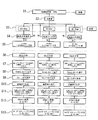
- FIG. 1 is a flowchart showing a method for producing a capturing material such as a micro-organism according to the first embodiment of the present invention.
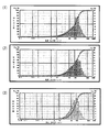
- FIG. 2 is a graph showing the particle size distribution of the capture material such as each micro-organism according to the first embodiment of the present invention.
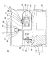
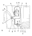
- FIG. 3 is a cross-sectional view showing a capture device for micro-organisms according to the second embodiment of the present invention.
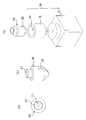
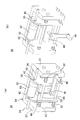
- FIG. 4 is a perspective view showing an agitation container and a drive unit of a capture device for micro-organisms according to the second embodiment of the present invention.
- FIG. 5 is a perspective view showing a desorber of the capture device for micro-organisms according to the second embodiment of the present invention.
- FIG. 1 is a flowchart showing a method for producing a capturing material such as a micro-organism according to the first embodiment of the present invention.
- FIG. 2 is a graph showing the particle size distribution of the capture material such as each micro-
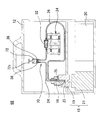
- FIG. 6 is a sectional view showing a capture device for micro-organisms according to the third embodiment of the present invention.
- FIG. 7 is a cross-sectional view showing a capture device for micro-organisms according to the fourth embodiment of the present invention.
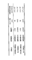
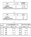
- FIG. 8 is a diagram showing an effect of using a capture material for micro organisms using the capture device for micro organisms according to the second embodiment of the present invention.
- FIG. 9 is a view showing a capture device for micro-organisms according to the fifth embodiment of the present invention.
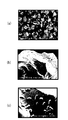
- FIG. 10 is a diagram showing an electron microscope image showing the powder body according to the embodiment of the present invention.
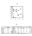
- FIG. 11 is a diagram showing a result of applying the method for storing micro-organisms according to the sixth embodiment of the present invention.
- FIG. 12 is a table showing processing using the capture apparatus or method for micro-organisms according to the third embodiment of the present invention.
- FIG. 13 is a table showing processing using a capturing apparatus or method for micro-organisms according to the third embodiment of the present invention.
- FIG. 14 is a table showing processing using a capturing apparatus or method for micro-organisms according to the third embodiment of the present invention.
- Micro-organism capturing device 14 60, 70 Micro-organism capturing section 11 Undefined shaped granular material (capturing material such as micro-organism) 16 Stirring container 23, 61 Suction port 24, 62 Suction channel 25 Discharge port 26 Discharge channel 32 Undefined-shaped granular material-enclosed column 34 Desorber
- FIG. 1 and FIG. 2 show a method for producing a capture material such as a micro organism according to the first embodiment of the present invention.
- the capture material for micro-organisms according to the present embodiment is an indeterminate-shaped powder particle formed of an adsorbable resin that can be pulverized, and an ion-exchange resin based on an insoluble and porous synthetic resin that can be pulverized
- the ion exchange resin material formed in (1) was further pulverized into a predetermined particle size range.
- the manufacturing method generally includes a pulverization step (corresponding to step S1) for manufacturing a granular material having a target particle size of 10 ⁇ m to 100 ⁇ m using a pulverizer, A classification process (corresponding to Steps S2 to S5) for sieving the powder particles and classifying them into powder particles of three particle size bands (particle size ranges), 180-90 ⁇ m, 90-46 ⁇ m, 46-25 ⁇ m
- the classified granular material has a granular material processing step (corresponding to Step S6 to Step S13) for performing various processes so that it can be used as the capture material such as the micro-organisms.
- Step S1 corresponding to the pulverization step is for pulverizing, for example, an unpulverized ion exchange resin material as the adsorptive resin material based on three types of pulverizable resins.
- ion exchange resin material As the ion exchange resin material, test number (1) is the strongest base gel type styrene type IRA400JCL (organo) wet product of anion exchange resin, and test number (2) is an anion exchange resin.
- spherical ion exchange resin particles each having a particle size of about 0.5 mm are used.
- pulverization was performed using a pulverizer (for example, a desktop impact pulverizer (sample mill SAM)) at a maximum rotational speed of 16000 min ⁇ 1 and using the inner speed.
- a pulverizer for example, a desktop impact pulverizer (sample mill SAM)
- the purpose of the treatment was to set the screen diameter to 0.5 mm or 0.3 mm for the purpose of producing a large number of powder particles in the range of 90 to 150 ⁇ m.
- FIG. 2 shows the measurement results of the distribution of particle sizes pulverized by the pulverizer for the test numbers (1), (2), and (3).
- the average particle size was 107 ⁇ m for test number (1), 108 ⁇ m for test number (2), and 111.9 ⁇ m for test number (3).
- the particle size distribution was measured using a particle size distribution meter (for example, SALD-2000J manufactured by Shimadzu Corporation).
- the classifying step corresponds to steps S2 to S5 in FIG. 1, in which the irregularly shaped powder obtained in step S1 is classified into three particle sizes as a particle size by a classifier.
- a classifier for example, sieving into a range of 180-90 ⁇ m, a range of 90-46 ⁇ m, and a range of 46-25 ⁇ m is performed.
- step S2 after drying the irregularly shaped particles, 100 g of the irregularly shaped particles are put into a classifier for any one of the ion exchange resins as the adsorbing resin.
- the classifier is, for example, four types of cylindrical bodies having a diameter of 200 mm provided with one stainless steel filter that can be connected to each other coaxially and having different pore diameters, and each cylindrical shape.
- a lid with a fixing bracket provided so as to be connectable to the upper end of the body, and provided with a plurality of fixing brackets extending along the axial direction for fixing the cylindrical bodies stacked together by screwing
- a saucer provided so as to be connectable to the lower end of each cylindrical body, and the lid with the fixing bracket, a combination of the four types of cylindrical bodies and the tray, and a stack of them fixed by the fixing bracket is shaken. Has a shaker.
- Each type of filter provided in each of the four types of cylindrical bodies is a stainless steel filter having different pore diameters, and the pore diameters are, for example, 180 ⁇ m, 90 ⁇ m, 46 ⁇ m, and 25 ⁇ m.
- the filter is provided so as to partition the cylindrical body vertically so as to cross the axis of each cylindrical body.
- the classifier includes a lid with a fixing bracket, a cylindrical body having a pore diameter of 180 ⁇ m, a 90 ⁇ m cylindrical body, a 46 ⁇ m cylindrical body, a 25 ⁇ m cylindrical body, and a tray connected in this order, and stacked. What is fixed with a fixing bracket is set on the shaker and shaken. Therefore, the irregularly shaped powder particles put into the classifier are accommodated in a cylindrical body having a filter with a pore diameter of 180 ⁇ m.
- the classification of the powder particles classified in this way is as follows. That is, they are 25-46 ⁇ m, 46-90 ⁇ m, 90-180 ⁇ m.
- step S3 the particle size distribution is measured in step S4 for each range of irregularly shaped powder particles that have been sieved, and it is confirmed that the number of particle size distributions outside the target classification range is 20% or less.
- step S5 the prescribed amount is collected and placed in a 250 ml sterile bottle containing 150 ml of sterilized 0.1% benzalkonium chloride solution and stored as a primary classified product. In addition, the granular material which was not classified in step S3 is stored separately.
- step S6 the range of 46-90 ⁇ m and 90-180 ⁇ m as the predetermined particle size of the classified irregularly shaped powder particles as capture materials for micro-organisms is 80 g in one treatment. In the range of 25-46 ⁇ m, 40 g is collected.
- step S7 the irregularly shaped granular material collected is suspended in 150 ⁇ m of a benzalkonium chloride solution and stirred well for 15 minutes. This removes the bacteria adhering to the irregularly shaped powder and removes fine particles that could not be classified.
- step S8 the suspension produced in step S7 is filtered using three types of filter screens of stainless steel filters each having a desired classified particle size, that is, a pore diameter of 90 ⁇ m, 46 ⁇ m, and 25 ⁇ m and a diameter of 200 mm. . Filtration is performed so as to spread uniformly on the filter. The liquid that has passed through is removed.
- Step S9 500 ml of 70% ethanol is put into a suspension bottle, resuspended so as to wash the remaining irregularly shaped powder particles, and then again filtered through the filter screen of the stainless steel filter.
- step S10 instead of ethanol, the suspension bottle is replaced with 200 ml of sterilized distilled water (DW) and resuspended so that the irregularly shaped powder particles are further washed. Filter through a sieve and drain well.
- DW sterilized distilled water
- step S11 the filter sieve is turned upside down, placed on the funnel, a 500 ml bottle is attached to the lower side of the funnel, and the irregularly shaped powder particles are peeled off from the filter sieve. .
- step S12 using an electric pipettor or the like from the back of the filtration sieve, pour sterilized distilled water so as to wash 400 ml, and peel off the irregularly shaped particles held on the filtration sieve (stainless steel filter), A 400 ml suspension is produced. Therefore, for an irregularly shaped granule with a particle size of 46-180 ⁇ m, the concentration is 0.2 g / ml, and for an irregularly shaped granule with a particle size of 25-46 ⁇ m, the concentration is 0.1 g / ml.
- step S13 375 ml of the generated suspension is dispensed into 125 tubes of 3 ml each, and various specimens are processed.
- a description will be given of a capture device 10 for micro-organisms according to a second embodiment, which is suitable for performing processing using the irregularly shaped powder particles 11 as the capture material for micro-organisms.
- the capturing apparatus 10 for micro-organisms includes a housing 12, a capturing section 14 for micro-organisms accommodated on the upper side of a partition plate 13 provided in the housing 12, and an inward side from the inner wall.
- a stirring vessel 16 having a protruding stirring wall portion 17, a rotation driving portion 18 provided so as to pass through the hole 15 of the partition plate 13, and rotating the stirring vessel 16, and under the partition plate 13
- a control unit for controlling the micro-organism capturing unit 14 and the rotation driving unit 18 and an electric circuit unit 20 storing a power source.
- the capture unit 14 for micro-organisms has one suction port portion 23 that is inserted into the stirring vessel 16 as a flow path and sucks a liquid.
- the suction port 23 is provided at a position close to the bottom through which the rotation axis of the stirring vessel 16 passes, so that substantially the entire amount of the liquid stored in the stirring vessel 16 can be sucked, and the discharge port 25 Is preferably provided at a position away from the suction port 23 and in the vicinity of the rotation axis in the region where the liquid in the stirring vessel 16 is accommodated.
- the capture unit 14 for micro-organisms has a bellows pump 30 as a pressure adjusting unit for adjusting the pressure in the flow paths 24 and 26.
- the bellows pump 30 has a bellows portion 31 that is compressed and recovered by an ascending / descending motion by a not-illustrated ascending / descending motion mechanism using a motor and a ball screw mechanism, and is provided in the suction flow path 24. It has been.
- the bellows pump 30 includes a one-way valve 36 for flowing liquid from the suction port 23 toward the bellows pump 30 and a one-way valve 38 for flowing liquid toward the discharge port 25.
- the capture unit 14 for micro-organisms is provided with an irregularly shaped granular material-entrapping column 32 formed in a cylindrical container as an irregularly shaped granular material holding part so as to be detachable from the flow paths 24 and 26. .
- the irregularly shaped granular material-enclosed column 32 is connected so as to communicate with a certain region that occupies a part of the flow path, here, between the suction flow path 24 and the discharge flow path 26.
- a predetermined amount of the irregularly shaped powder body 11 in a predetermined particle size range that can come into contact with the liquid sucked from the suction port portion 23 is enclosed as a capturing material such as the micro-organism.
- the irregular-shaped granular material-enclosed column 32 two filters 28 and 29 having a pore diameter smaller than the predetermined particle size range are crossed in the axial direction of the irregular-shaped granular particle-encapsulated column 32 of the cylindrical container. In the direction, that is, at both ends of the cylindrical container so as to divide the flow path, enclose and hold the irregularly shaped powder 11 in the predetermined particle size range so as to be sandwiched between the filters 28 and 29. To do.
- the volume is preferably determined by the type, nature, concentration, concentration rate, amount, flow rate, etc. of the liquid.
- connection short tubes protrude outwardly along the axis thereof, and are detachably connected to the suction flow channel 24 and the discharge flow channel 26, respectively. Attached.
- the micro organism capturing apparatus 10 further includes a column desorber 34 having two movable plates 42 driven by a cam 40 in order to desorb the irregularly shaped granular particle-containing column 32.
- the rotation drive unit 18 includes a coupler 19 that is fitted to the stirring container 16 and detachably attaches the stirring container 16, and a motor shaft is fixed to the coupler 19, and is fitted to the coupler 19. And a motor 21 for rotationally driving the stirring vessel 16 attached together.
- the agitation vessel 16 is formed in a substantially cylindrical shape as a whole, and the agitation vessel 16 has a side wall and a bottom that are recessed toward the rotation axis and along the rotation axis.
- a stirring wall portion 17 having a flat surface extending along the radial direction of the container 16 and the two directions of the rotation axis is provided.
- the rotation axis substantially coincides with the axis of the stirring vessel 16, and the stirring wall portion 17 protrudes in the radial direction toward the rotation axis but does not exceed the rotation axis.
- the suction flow path 24 is inserted into the stirring container 16 through the opening 27 along the rotation axis of the stirring container 16, and the suction port 23 is formed at the bottom of the stirring container 16. It is provided in close proximity without touching.
- the discharge port portion 25 of the discharge flow channel 26 is inserted so as to be higher than the discharge port portion 25 and higher than the height of the stirring wall portion 17 at a position deviated from the rotation axis. Has been.
- control part which controls these capture devices 10 for micro-organisms, an input device for inputting instructions and data from a user, a CPU for performing various calculations, a display device, various memories, a transmission means, etc. It is preferable that an information processing apparatus having the above is provided in the electric circuit unit 20.
- the control unit instructs the pressure adjusting mechanism of the capture device 10 for micro-organisms, a desorber and the like, and receives signals from these devices.
- the controller controls the pressure level in the flow path by the pressure adjusting mechanism or the time thereof, or the amount, speed, or time of suction or discharge, the structure of the flow path, and the irregularly shaped powder and particles.
- Structure including the structure of the pore diameter of the filter, etc.
- type, particle size or amount of the irregularly shaped powder particles held in the irregular shape powder particle holding unit the amount or type of liquid, the target Control to be determined based on type, concentration, purpose of treatment, time or concentration rate (or dilution rate).
- FIG. 4 shows the agitation container 16 and the rotation drive unit 18.
- the back side of the stirring wall portion 17 is a slit-like gap portion 22 that is recessed in the radial direction toward the inside of the stirring vessel 16 and extends in the axial direction.
- a fitting plate 44 that protrudes along the radial direction toward the rotation axis is fitted into the gap portion 22 on the inner wall of the coupler 19 of the rotation driving portion 18, and the stirring vessel 16 and the motor
- the coupler 19 coupled coaxially with the coupling 21 is coupled coaxially, so that the rotational motion of the motor 21 can be reliably transmitted to the rotational motion of the stirring vessel 16.
- FIG. 5 shows the column desorber 34 in detail.
- the column desorber 34 is attached to the housing 12 and is bent so as to be orthogonal to the mounting side surface 55 on both sides of the mounting side surface 55, so that the irregularly shaped granular material-enclosed column 32, two opposing support side surfaces 57 that support the suction flow channel 24 and the discharge flow channel 26 that are inserted up to the middle of the connecting short tube 33 that protrudes from both ends of the 32
- the frame body 54 is made of.
- the two movable plates 42 have a U-shaped groove 56 provided by cutting out the upper end thereof, and the groove 56 is connected to the connecting short tube 33 of the irregularly shaped granular material-containing column 32.
- the irregularly shaped granular material-containing column 32 is supported so as to come into contact with each other.
- the movable plate 42 is provided so as to be slidable along the shaft 50 that passes through the movable plate 42 and spans between the support side surfaces 57, and between the support side surface 57 and the movable plate 42. It is urged
- the cam 40 is provided so as to be sandwiched between the movable plates 42.
- the cam 40 is formed in a substantially rectangular plate, a cam shaft 41 perpendicular to the plane is provided at the center of the plate, and a handle 48 for rotating the cam 40 is provided on the cam shaft 41.
- the length of the cam 40 in the longitudinal direction is such that the distance between the two movable plates 42 is most separated, and the mouths of the suction flow path 24 and the discharge flow path 26 extend from the connection short tube 33. It is possible to disengage, but the groove 56 is set to a range that does not disengage from the connecting short tube 33.
- the apexes at the four corners of the cam 40 are chamfered with curved surfaces corresponding to the rotation radius so as to make smooth contact with the movable plate 42.
- FIG. 5A shows a state in which the movable plate 42 is biased by a spring and pressed against the indefinite shape granular material-enclosed column 32, and no force is applied to the mouth of the discharge channel 26. That is, an irregularly shaped granular material-enclosed column 32 is attached to the discharge flow channel 26 via the short tube
- FIG. 5B shows a direction in which the movable plates 42 are separated from each other by the cam.
- the discharge flow channel 26 is peeled outward from the connection short tube 33 by the groove 56 of the movable plate 42, that is, the irregularly shaped granular material-enclosed column from the discharge flow channel 26. 32 shows a state where it is detached.
- FIG. 6 shows a capture device 58 for micro-organisms according to the third embodiment.
- the micro organism capture device 58 uses a peristaltic pump (peristaltic pump) instead of a bellows pump.
- peristaltic pump peristaltic pump
- the micro organism capturing device 58 has a micro organism capturing section 60 accommodated on the upper side of the partition plate 13 provided in the housing 12.
- the micro organism capturing section 60 is formed of an elastic resin such as a fluororesin rubber or silicon having one suction port section 61 that is inserted into the stirring container 16 and sucks a liquid as the flow path.
- the liquid feeding section 59 has two openings through which the suction flow path 62 is inserted, and the suction flow path 62 is U-shaped along the inner wall in the interior from the opening to the opening.
- a cylindrical frame 67 which is stored in a curved manner, and is provided concentrically with the cylindrical frame 67 so as to have a space capable of storing the suction flow path 62 between the inner wall of the cylindrical frame 67 and the like.
- a roller 63 that is rotationally driven by a motor that does not rotate, and is provided on the roller 63, protrudes in the radial direction of the roller 63, protrudes from the radius of the roller 63, and passes through the suction flow path 62 accommodated in the cylindrical frame 67.
- it has the handling part 66 provided in two places on both sides of the rotating shaft which rotates with the said roller 63. As shown in FIG.
- FIG. 7 shows a capture device 68 for micro-organisms according to the fourth embodiment.
- the micro organism capture device 68 uses a cylindrical pump 72 instead of the bellows pump 30.
- the same components as those in FIG. 3 are denoted by the same reference numerals, and detailed description thereof is omitted.
- the micro organism capturing device 68 includes the housing 12 and a micro organism capturing section 70 housed on the upper side of the partition plate 13 provided in the housing 12.
- the suction port portion is moved up and down by a piston 72a sliding in the cylinder by an ascending / descending motion by an unillustrated ascending / descending motion mechanism using a motor and a ball screw mechanism.
- the fluid is sucked through 23 and the fluid is discharged from the discharge port portion 25.
- Legionella bacteria (Legionella spp.) In the heat storage tank water to be inspected are concentrated for the purpose of the Legionella culturing test using the micro-organism capturing apparatus 10 according to the second embodiment described above.
- step S21 for example, the micro organism capturing device 10 according to the second embodiment is transported to the tank of the heat storage tank water in which the bacteria are suspended, and the micro organism capturing unit 14 is transported.
- the suction port portion 23 of the suction flow channel 24 and the discharge port portion 25 of the discharge flow channel 26 are extended to the outside of the housing 12, and the inside of the tank is replaced with the stirring vessel 16. It is inserted into the heat storage tank and installed, and the bellows pump 30 is operated for about 30 minutes to process 5 liters.
- step S22 the irregularly shaped granular particle-containing column 32 is desorbed from the capture unit 14 for micro-organisms.
- step S23 the irregular shaped granular material 11 is taken out from the irregular shaped granular particle-entrapping column 32 as a capturing material for the micro-organisms, and the irregular shaped granular material 11 is added with 0.5 ml of 0.1M HCl-KCl (pH 2.2). Fill powder 11 and let stand at 25 ° C. for 4 minutes.
- step S24 the irregularly shaped granular material 11 is stirred 10 times with a detachment solution (eluate) and allowed to stand for 5 minutes, and then the detachment solution is recovered.
- a detachment solution eluate
- step S25 the sample is diluted 10-fold with physiological saline as necessary, and 100 ⁇ l is applied to the Legionella selective medium WYO ⁇ plate.
- step S26 the cells are cultured at 37 ° C. for 5 to 7 days while preventing drying.
- step S31 if the same heat storage tank water is spent in the same amount of processing time, 200 ml of heat storage tank water is placed in a sterilized centrifuge tube, loaded into a centrifuge, and centrifuged at 6000 rpm for 20 minutes at 4 ° C. .
- step S32 1 ml of precipitate is left and the supernatant is removed.
- step S33 1 ml of 0.2M HCl-KCl (pH 2.2) is added, and the mixture is allowed to stand at 25 ° C. for 4 minutes.
- step S34 100 ⁇ l is applied to Legionella selective medium WYO ⁇ plate.
- step S35 the cells are cultured at 37 ° C. for 5 to 7 days while preventing drying.
- the number of colonies in FIG. 8 is the number of viable bacteria present in 0.1 ml.
- the “initial bacterial cell concentration” is calculated by multiplying the “colony number” by the dilution rate or the concentration rate, and indicates the number of viable cells present in 100 ml of heat storage tank water.
- the sensitivity is 47 to 79 times that of the conventional cooling centrifuge method from the number of colonies.
- the same results were obtained with the method using the apparatus according to the present embodiment and the conventional cooling centrifuge method.
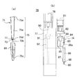
- FIG. 9A shows a column chip 71 corresponding to a capture unit for micro-organisms according to the fifth embodiment of the present invention
- FIG. 9B shows a column chip drive mechanism for driving the column chip 71. 76 is shown.
- the column tip 71 includes a large-diameter tube 75a in which the irregularly shaped powder particles 11 serving as a capture material for micro-organisms are accommodated, and a small-diameter tube 75b provided with a mouth portion 75c capable of inflow and outflow of liquid.
- the particle size 11 of the irregularly shaped powder 11 is 180 to 90 ⁇ m, and when 40 mg of the powder is accommodated on the filter 73, it is about 5 mm. It will be about 1cm thick. In this case, the number of powder particles is about 25,000.
- the mouth portion 75c at the tip of the small-diameter tube 75b is inserted into a container 69 that contains a liquid to be processed.
- the column chip drive mechanism 76 has a nozzle head 74 having the nozzle 80.
- a connecting portion 87 provided with a pipe line 98 that is connected to a cylinder 86 provided slightly above the nozzle 80 and that guides gas to a pressure sensor (not shown) in order to detect the pressure in the nozzle 80.
- a cylinder 86 connected to the nozzle 80 via the connecting portion 87, a piston 86a that slides in the cylinder 86, and a rod 83 that drives the piston 86a are provided.
- the rod 83 is attached to a notch portion provided at the edge of the drive plate 94 capable of moving up and down so as to hang 83a protruding from the radial end with a diameter larger than the diameter of the rod 83. Yes.
- the nozzle head 74 is movable in the horizontal direction or the horizontal direction in the drawing.
- the drive plate 94 is connected to a nut portion 84 that is screwed with the ball screw 85.
- the rod 83 is always urged downward by a spring provided in the cylinder 86. Therefore, the rod 83 is raised by the nuts 84 when moving upward, but is lowered by the spring force, not by the nuts 84, when lowering.
- Each of the ball screws 85 is rotationally driven by a motor 81 provided on a U-shaped support member 82, whereby the drive plate 94 and the rod 83 move up and down all at once.
- the case 77 has a ball screw 90, a nut portion 91 screwed into the ball screw 90, and a support body 92 having the support member 82 attached to the nut portion 91 at one end.
- a motor 78 that rotationally drives the ball screw 90 is provided on the case 77.
- the nozzle 80 can be moved up and down by an up-and-down mechanism constituted by these parts.
- the column chip driving mechanism 76 is provided so as to be suspended from the upper side in the housing.
- the column chip 71 that is the capture unit for micro organisms, the degree of capture when capturing E. coli as micro organisms, etc., when the irregularly shaped granular material 11 as the capture material for micro organisms is used And the case of using a pulverizable adsorptive resin material.
- the E. coli solution in which E. coli is suspended, the E. coli solution is stored in the container 69 when the turbidity OD 660 is 0.505.
- the column tip 71 is attached to the nozzle 80 of the column tip driving mechanism 76 through the attachment opening 75e, and the mouth portion 75c at the tip of the column tip 71 is inserted into the container 69, and the process is repeated five times. Repeat suction and discharge.
- Escherichia coli in the Escherichia coli solution is adsorbed and captured on the surface of the irregular shaped granular material 11, and a residual liquid containing the uncaptured Escherichia coli passes through the mouth 75 c into the container 69. Discharged.
- FIG. 10A shows a large number of irregularly shaped powders 11 formed of a strongly basic gel-type ion exchange resin (Model No. IRA410JCL from Organo).
- FIG. 10B shows an image obtained by an electron microscope in which a state in which a large number of E. coli is adsorbed on one of the powder particles 11 is enlarged.
- FIG.10 (c) shows the image by the electron microscope which expanded the said granular material 11 further. E. coli adsorbed with many spots visible on the surface of the granular material 11. If the size of the granular material 11 is 180 to 90 ⁇ m, the number of the granular material 11 per 20 mg is about 12000, and the surface area when converted as a sphere is about 7.1 cm 2 .
- the E. coli size is close to 1 to 1.5 ⁇ m in length and 2 to 6 ⁇ m in width, and that the cells can be spread on the granular material
- the total number of E. coli present in the solution is calculated in this experiment. it is considered from 9 ⁇ 10 7 and 3.2 ⁇ 10 8, 1 single granular material per approximately 9 ⁇ 10 7/12000 from 3.2 ⁇ 10 8/12000 or E. coli is capable of adsorption.
- the column chip 71 measurement is performed by using a non-pulverized resin material that can be pulverized instead of the irregularly shaped powder particles 11 as the capturing material such as micro-organisms.
- the tip 75c of the tip container 75 is inserted into the container 69, and suction and discharge are repeated five times. Then, E. coli in the E. coli solution is captured on the surface of the pulverizable resin material, and the remaining liquid containing E. coli that has not been captured is discharged into the container 69 through the mouth 75c.
- the turbidity OD 600 0.328. That is, it can be seen that the degree of capture by the column tip 71 is larger than that when an unground pulverizable resin material is used.
- a method for storing Legionella contained in a sample obtained by applying the powder 11 for capturing Legionella for example, Legionella spp. Pneumophila spp.
- a sample extracted from a real sample heat storage tank water
- the particle size of the granular material 11 is classified into a range of 90 to 250 ⁇ m.
- the table shown in FIG. 11 (a) is obtained by adding about 10 3 to 10 4 cfu / ml Legionella pneumophila sp. SG1 serotype in physiological saline conditions or adding 100 mg of the granular material 11 to 4
- the figure shows the number of colonies when stored at 0 ° C. or 37 ° C. and cultured for 5 days on a BCYE ⁇ agar medium (BD) after 0 to 10 days.
- the graph shown in FIG. 11B is a plot of the percentage of the number of colonies as the survival rate when the number of colonies on day 0 is 100%.
- a specimen is mainly sent to a facility by a cool flight, and then concentrated by the centrifugation method or the filter method described above, and detected by culture or nucleic acid amplification (LAMP method).
- FIGS. 11 (a) and 11 (b) it is shown that storage at room temperature is impossible.
- the conventional preservation solution containing only physiological saline shows a survival rate of 60% or less on the 5th day, and then the survival rate rapidly decreases.
- the granular material 11 according to the present embodiment it is shown that a survival rate of about 80% is maintained even after 10 days.
- Concentration and recovery are carried out using the granular material 11 classified into a particle size range of 90 to 250 ⁇ m, the micro-organism capturing device 58 according to the third embodiment, the irregular-shaped granular material-containing column 32, and the like. Describes examples carried out using culture, immunochromatography, and nucleic acid amplification in comparison with the results of centrifugation.
- the roller 63 of the peristaltic pump of the micro organism capturing device 58 used for the concentration and recovery is rotationally driven by a stepping motor, and the rotational speed thereof can be adjusted between 40 and 150 rpm.
- a silicon tube (ASONE) having an inner diameter of 5 mm and an outer diameter of 9 mm, or a soft PVC tube (SANYO KASEI) having an inner diameter of 6 mm and an outer diameter of 9 mm is used.
- a filter having a diameter of 12 mm is used for outdoor use, and a filter having a diameter of 8 mm is used for indoor use.
- the pore diameter of these filters is considered to be about 10 ⁇ m.
- the Legionella treatment includes a concentration step in step S41, a recovery step in step S42, and a detection step in step S43.
- the irregularly shaped granular particle-containing column 32 is mounted on the micro-organism capturing device 58, and the pump is driven for a time corresponding to the capacity.
- the pump is driven for a time corresponding to the capacity.
- 200 mg of the granular material 11 is sealed so as to be sandwiched by the filter having a diameter of 12 mm, and the concentration treatment is performed for 30 to 60 minutes.
- four heat storage tank waters of SY, YJ, YA, and CK were used as actual samples.
- step S42 the irregularly shaped granular material-entrapped column 32 is recovered, and the granular material is slowly stirred, for example, 20 times with 250 ⁇ l or 500 ⁇ l of eluent using a syringe.
- a syringe is inserted into the lower part of the irregular-shaped granular material-containing column 32, left still for 5 minutes, stirred 20 times, and the eluate is transferred to a 1.5 ml tube.
- the HCl treatment is performed, the particles are immersed in 1 ml of HCl solution for 4 minutes before the elution operation, and the elution operation is performed after discarding the HCl solution.
- the type of eluate is determined depending on the detection method in the next detection step.
- step S43 when culture is used, 1M KPB is used as the eluate of step S42.
- the eluate is applied as a culture medium, for example, to a WYO ⁇ agar medium (Eiken Chemical Co., E-MR70).
- step S43 When detection by immunochromatography is performed in the detection step of step S43, 250 ⁇ l or 500 ⁇ l of 3M TB buffer is put into a 1 ml syringe as the eluate, and the irregularly shaped granular material-enclosed column It inserts in 32 and performs the stirring mentioned above. Then, 100 ⁇ l of 1M KPB development buffer is mixed. By this mixing, aggregation of the bacteria with iron can be released. 100 ⁇ l of this mixed solution was applied to an immunochromatographic test strip, and the degree of color development after 15 minutes was recorded. The color developed was judged positive and the color not developed was judged negative.
- the immunochromatographic test strip is for the Legionella pneumophila sp. SG1 serotype.
- step S43 when nucleic acid amplification by a PCR method and detection by an electrophoretic image are performed, in the heat storage tank water sample, metals such as iron oxide and metal ions tend to be mixed and inhibit PCR. Therefore, it is necessary to perform an amplification operation after the nucleic acid extraction operation in which the sample is purified by simultaneously removing metal ions and lysing bacteria using an alkaline solution (for example, Niigata Prefectural Institute of Health and Environmental Science, Vol. 15). 2000).
- an alkaline solution for example, Niigata Prefectural Institute of Health and Environmental Science, Vol. 15). 2000.
- the concentration method by the cooling centrifuge method described in “Revision and Legionella Control Guidelines (March 1999)” was carried out.
- a 200 ml sample was collected, dispensed into a 50 ml centrifuge tube, cooled and centrifuged at 6000 rpm (the centrifugal force G is not described) for 20 minutes, and then slowly decanted.
- the precipitate was suspended in a total of 1 ml of sterile distilled water, 1 ml of 0.2 M HCl ⁇ KCl (pH 2.2) was added, and the mixture was allowed to stand for 4 minutes. Thereafter, 100 ⁇ l was applied to WYO ⁇ medium and cultured at 37 ° C. for 5 to 7 days while preventing drying.
- the concentration operation is performed directly from the heat storage tank CK using the concentration device, and when detected by the immunochromatography method, the immunochromatographic test strip to which 100 ⁇ l of the concentrate is applied is 5 minutes after the development. A slight line was detected, and a clear line was confirmed after 15 minutes.
- FIG. 12 (a) shows the result of concentration culture of each of the heat storage tank water YJ and Legionella spp. Pneumophila sp. SG1 serotype cultured in the heat storage tank water by the cooling centrifuge method
- FIG. 12 (b) shows the liquid that has passed through the irregular-shaped granular material-enclosed column 32 when concentrated from 5 liters of the sample using the micro-organism capturing apparatus 58 according to the embodiment of the present invention. From the difference of the result of concentration culture by the above, the adsorption rate to the granular material 11 is calculated.
- FIG.12 (c) shows the result of having concentrated the sample from four heat storage tanks using the capture apparatus, such as a micro organism concerning this Embodiment, and having detected with the immunochromatography method, culture
- FIG. 13 shows the result when the capture device 58 for micro-organisms according to the above embodiment is used for indoor use.
- FIG. 13 (a) shows the number of colonies and the initial concentration per culture dish as a result of concentration culture of the passed liquid by the cooling centrifugal concentration method. Moreover, what computed the adsorption rate from each culture result with respect to control is shown in FIG.13 (b). From these results, it can be said that the concentration efficiency becomes relatively high by extending the circulation time.
- FIG. 14 shows the results of culturing using the capture device or method for outdoor and indoor micro-organisms and the results of the cooling centrifugation method.
- the parentheses in the number of colonies indicate the number of contaminated colonies, and in the “No.” column, “0” indicates the result of the cooling centrifugal concentration method, and “1”-“4” indicates this
- the capture device 58 for micro-organisms according to the embodiment of the invention is used.
- the HCl treatment is not necessarily required as long as the capture device 58 or method for micro-organisms according to the embodiment of the present invention is used. This is thought to be due to the nature of the powder 11 that does not adsorb many cells and the surface layer of the powder 11 is locally acidic.
- the capturing apparatus and method for micro-organisms using the powder 11 according to the embodiment of the present invention can be applied to the culture method.
- the capture efficiency of the outdoor sample was 50% or more when the pump was driven for 30 to 60 minutes.
- the operation of concentrating from 500 ml to 1000 times was possible.
- the adsorption rate in the indoor sample was 80% or more by circulating for 15 to 30 minutes.
- the capture apparatus and method for micro-organisms according to the embodiment of the present invention show the same concentration efficiency as the guide method, and it is possible to lower the detection limit for indoor samples with a concentration of 10 to 20 times. It was.
- a large-scale apparatus is not required, and the concentration operation can be performed in a place where a sample to be examined exists, not in a laboratory. It is. Therefore, there is no need to transport a sample for inspection purposes.
- a large volume (500 ml or more) concentration operation which is difficult with a centrifugal operation or a filtration operation, is easy and requires less labor.
- it can be directly connected to a detection method that requires high concentration, such as immunochromatography, which is difficult to perform by centrifugation or filtration.
- simple operation is possible even if it is not a trained tester such as a researcher.
- a sample containing a target such as a micro organism can be stored with a high survival rate even when the sample is transported.
- the present invention can be changed without changing the gist of the invention.
- the production and processing of irregularly shaped powder particles as capture materials such as micro-organisms were mainly performed for about three types of ion exchange resins, but other pulverizable adsorptive resins, for example, In addition to other ion exchange resins, pulverizable chelate resins and pulverizable adsorbents can be used.
- the irregularly shaped granular material-enclosed column 32 is mainly provided on the downstream side of the bellows pump, the liquid feed part of the peristaltic pump, and the cylinder type pump, but may be provided on the upstream side. Moreover, although only the apparatus provided with each of these pumps or nozzles was described, a plurality of them may be arranged, and these may be provided in the same apparatus or may be provided in parallel. Moreover, although the process of Legionella was mainly demonstrated, it is not restricted to the process of this Legionella, The process of other bacteria, protozoa, a cell, etc. may be sufficient.
- targets such as bacteria, protozoa, biological tissues, cells, micro-organisms such as viruses, immune substances such as antibodies and antigens, genetic substances (DNA, RNA, mRNA, oligonucleotides, etc.) It is used to perform processing such as extraction, analysis, and inspection of biopolymers such as proteins and hormone substances, and other useful substances such as other medical drugs. In addition, it is used for medical, examination, diagnosis, treatment, research, quantification, qualitative, and measurement that automatically and reliably perform separation, extraction, concentration, etc. of minute targets such as micro-organisms such as cells. .
Landscapes
- Chemical & Material Sciences (AREA)
- Organic Chemistry (AREA)
- Chemical Kinetics & Catalysis (AREA)
- Analytical Chemistry (AREA)
- Health & Medical Sciences (AREA)
- Life Sciences & Earth Sciences (AREA)
- Zoology (AREA)
- Wood Science & Technology (AREA)
- Proteomics, Peptides & Aminoacids (AREA)
- Engineering & Computer Science (AREA)
- Molecular Biology (AREA)
- General Health & Medical Sciences (AREA)
- Immunology (AREA)
- Biotechnology (AREA)
- Biophysics (AREA)
- Physics & Mathematics (AREA)
- Biochemistry (AREA)
- Bioinformatics & Cheminformatics (AREA)
- General Engineering & Computer Science (AREA)
- Microbiology (AREA)
- Genetics & Genomics (AREA)
- Pathology (AREA)
- Solid-Sorbent Or Filter-Aiding Compositions (AREA)
- Apparatus Associated With Microorganisms And Enzymes (AREA)
- Sampling And Sample Adjustment (AREA)
- Treatment Of Water By Ion Exchange (AREA)
- Water Treatment By Sorption (AREA)
Abstract
本発明は、微小生物等捕獲材、微小生物等捕獲装置、微小生物等捕獲方法および微小生物等捕獲材製造方法に係り、大量の液体中に含有した微少量の微小生物等または少量の液体中に含有した微小生物等をも効率的、迅速、低労力で、かつ確実に捕獲することができる粉砕可能な樹脂を利用することを目的とするものであり、粉砕可能な吸着性樹脂で形成された所定粒度の範囲に分布する不定形状の粉粒体からなり液中の微小生物等の標的の吸着もしくは結合可能な微小生物等捕獲材、微小生物等捕獲装置および微小生物等捕獲方法である。さらに、本発明は、上記の粉粒体を標的を含有する液体中に懸濁させる工程を有する、標的である微小生物等の保管方法に関するものである。
Description
本発明は、微小生物等捕獲材、微小生物等捕獲装置、微小生物等捕獲方法および微小生物等捕獲材製造方法に係る。特に、工業分野、医療分野、農業分野、理学分野、製剤分野等の様々な分野で利用可能である。
近年、病院等において、細菌等(例えば、O157、O26等の大腸菌、レジオネラ菌、クリプトスポリジウム、サルモネラ菌、赤痢菌、キャンピロバクター菌等の水系溶存細菌、原虫等)の微小物質について、分離、抽出、検査、測定等の種々の処理を行う必要性が高まっている。
特に、レジオネラ菌による事故や症例の報告が近年急増している。レジオネラ症は、1998年12月に「感染症の予防および感染症の患者に対する医療に関する法律(感染症新法)」により、4類感染症に指定されたもので、高齢者や免疫不全、抵抗力が弱まった状態で死に至る危険性を有する。そのため、原因の究明、レジオネラ菌の安定した検出、迅速な検出が要求されている。
前記細菌等の微小生物は、大量(例えば、50mlから10リットル程度)の液体(例えば、血液、ジュース、便、汚水等)に微少量懸濁した状態で得られるのが普通である。この微小生物について培養や増幅等を行ったり、O抗原や、Verotoxin (VT)遺伝子を検出するためのPCR等の種々の処理は、前記微小生物の濃度を高めた上で行う必要性があった。
例えば、前記レジオネラ症については、「新版レジオネラ症防止指針」によると、浴槽など人体が直接触れる環境水の検査で1cfu/100ml(cfu: colony forming unit)であった場合、冷却塔や蓄熱槽等の環境水の検査で10cfu/100mlであった場合に直ちに塩素消毒することと定められている。このボーダーラインを検出するためには、数100mlの大量の試料からのレジオネラ菌濃縮を必要とする。
そのため、従来では、前記微小生物が懸濁する大量(例えば、1リットル以上程度)の懸濁液を濾過フィルタや除菌フィルタを通過させることによって、または遠心分離によって、さらには、培地で培養することによって、分離、抽出を行っていた。しかし、通常、その懸濁液には標的以外の夾雑物が数多く含まれており、そのような濁りや汚れがあるために、菌体よりも小さなポアサイズを用いた濾過フィルタや除菌フィルタがメンブレンフィルタ等の場合には、効率の悪さがしばしば指摘されたり、それらのフィルタが目詰まりを起こしたり、望まない不要物の回収がなされるという欠点があった。また、遠心分離を用いる場合には、例えば、1mlをチューブに採って、11000rpmで10分間遠心分離を行なうような場合が通常であって、1リットル以上程度の大量の液体を一度で扱うことは、装置規模からほとんど困難であった。このように、従来では、大容量の懸濁物から標的を分離するのが困難または時間や手間がかかるという問題点を有していた。
また、細菌等のように人間等の生物に影響を与えるものを扱う場合を考慮して、人間の手を煩わせることの少ない、自動的に処理を行えるとともに、懸濁液の接液部分の取り替えが可能で洗浄の必要性がなく効率良く使用できかつ信頼性のある装置が望まれている。
なお、細菌等の微小生物等を捕獲するには、細菌等のサイズに応じた適切なサイズの捕獲材を用いることによって、その捕獲効率を高めることができることが知られている。
そこで、本発明の第1の目的は、大量(例えば、約50ml以上で約10リットル未満)の液体中に含有した微少量の微小生物等または少量(例えば、約50ml未満)の液体中に含有した微小生物等をも効率的、迅速、低労力で、かつ確実に捕獲することができる微小生物等捕獲材、微小生物等捕獲装置、微小生物等捕獲方法および微小生物等捕獲材製造方法を提供することである。
第2の目的は、液体中に含まれる標的以外の夾雑物の存在によって濃縮、分離または抽出処理に影響を受けない微小生物等捕獲材、微小生物等捕獲装置、微小生物等捕獲方法および微小生物等捕獲材製造方法を提供することである。
第3の目的は、単純な機構および低価格の素材を用いることによって、また、懸濁液との接液部分が容器やディスポ・チップ等の取り替え可能となる構造をとることで、クロスコンタミネーションを防止し、また低価格で、かつ扱い易い微小生物等捕獲材、微小生物等捕獲装置、微小生物等捕獲方法および微小生物等捕獲材製造方法を提供することである。
第4の目的は、人間の手を煩わせることのない自動化処理および一貫性のある処理に適した微小生物等捕獲材、微小生物等捕獲装置、微小生物等捕獲方法および微小生物等捕獲材製造方法を提供することである。
第5の目的は、簡単で小規模な構造の装置を使うことができるので、検査したい試料が存在する場所で処理を行うことができるため、試料の輸送を必要とせず、細菌等の微小生物等を扱うのに適した微小生物等捕獲材、微小生物等捕獲装置、微小生物等捕獲方法および微小生物等捕獲材製造方法を提供することである。
第6の目的は、検体中の標的である微小生物を、高い生存率で保管することができる微小生物等保管方法を提供することである。
森崎久雄、服部黎子著「界面と微生物」学会出版センター 1986年 14頁、92頁から103頁
以上の技術的課題を解決するために、第1の発明は、粉砕可能な吸着性樹脂で形成され所定粒度の範囲に分布する不定形状の粉粒体からなり液中に含有する標的を吸着もしくは結合することが可能な微小生物等捕獲材である。
ここで、「粉砕可能な樹脂」とは、常温で固体の不溶性の樹脂であって、第1には、弾性が小さく配向性や結晶性がある程度大きい、天然樹脂、合成繊維や所定の合成樹脂である。第2には、弾性が第1の場合よりも大きく常温で粉砕に適さない場合には、ガラス転移温度以下のガラス状態の樹脂、または、前記ガラス転移温度以下かつ低温脆化点以下の状態にある樹脂である。ここで、第1の場合の天然樹脂としては、天然のセルロースを含有する木片等、第1の場合の合成繊維としては、ナイロン、ビニロン、アクリル繊維、レーヨン等があり、第1の場合の所定の合成樹脂としては、重合度が小さなプレポリマー(これに硬化剤を加えることもある)を加熱し分子間に三次元的な架橋を形成させた熱硬化性樹脂である。熱硬化性樹脂には、ホルムアルデヒド樹脂と架橋型樹脂とがあり、ホルムアルデヒド樹脂とは、ホルムアルデヒドとの縮合反応で架橋・硬化を行うタイプであってフェノール樹脂とアミノ樹脂がある。架橋型樹脂とは、架橋をホルムアルデヒドとの縮合以外の反応を利用するタイプであって、不飽和ポリエステル樹脂、ジアリルフタレート樹脂、アルキド樹脂、エポキシ樹脂、ウレタン樹脂、ケイ素樹脂がある。第2の場合の樹脂としては、例えば、天然ゴム、ポリイソプレン、ブタジエン等の合成ゴム、または、固体状の鎖状ポリマーからなり、加熱により可塑性が生ずる熱可塑性樹脂がある。熱可塑性樹脂としては、例えば、塩化ビニル樹脂、ポリエチレン、ポリプロピレン等がある。
「粉砕可能な吸着性樹脂」とは、粉砕可能な前記樹脂の内、後述する標的に対して吸着性もしくは結合性をもつ不溶性の樹脂であって、粉砕可能なイオン交換樹脂およびその他が含まれる。粉砕可能なイオン交換樹脂としては、前記粉砕可能な樹脂を母体として、イオン交換できる酸性基、塩基性基等を持たせたものであって、粉砕可能な陽イオン交換樹脂、粉砕可能な陰イオン交換樹脂、粉砕可能な両性イオン交換樹脂の3種類がある。前記母体の樹脂としては多孔性であるものがより好ましい。
粉砕可能な陽イオン交換樹脂は、例えば、ジビニルベンゼンで架橋したポリスチレン等を母体とした合成樹脂(R)に、酸性水酸基、カルボキシル基、スルホ基等の酸性基が結合した高分子酸である。ヒドロニウムイオンH3O+を生じ、それが水中の塩基または中性塩の陽イオンと交換する。
粉砕可能な陽イオンのイオン交換樹脂材としては、市販のものとして、例えば、弱酸性MR形(オルガノ社の型番IRC76AG)で母体構造がアクリル系のものと、強酸性ゲル形(オルガノ社の型番IR120BNA)で母体構造がスチレン系のものがあり、各々粒度は約0.5mmの真球状である。
粉砕可能な陰イオン交換樹脂は、例えば、ジビニルベンゼンで架橋したポリスチレン等を母体とした合成樹脂(R)に、アミノ基、イミノ基、アンモニウム塩等の塩基性基が結合した高分子塩基である。粉砕可能な陰イオンのイオン交換樹脂材としては、市販のものとして、例えば、弱塩基性MR形(オルガノ社の型番IRA96SB)、強塩基性ゲル形(オルガノ社の型番IRA410JCL)、最強塩基性ゲル形(オルガノ社の型番IRA400JCL)のものがあり、粒度は約0.5mmの真球状であって、その母体構造としてはスチレン系のものがある。両性イオン交換樹脂は、酸性基と塩基性基の両方を交換基として持つイオン交換樹脂である。一般に、イオン交換樹脂は再生可能で繰り返し使用可能である。陰イオン交換樹脂には、他に三菱化学ダイヤイオンSAシリーズ、PAシリーズ、HPAシリーズ、WAシリーズ 等の入手可能な製品がある。
前記「その他」の粉砕可能な吸着性樹脂としては、粉砕可能なキレート樹脂、粉砕可能な吸着材、および、前記粉砕可能な樹脂に官能基をもたせるとともに、該官能基に、前記他の物質として、微小生物、ウィルスまたは前記生体高分子の標的が有する受容体に結合性を有するリガンドを結合させた粉砕可能なリガンド結合樹脂を含む。ここで、リガンドとしては、前記受容体としての、核酸等の遺伝物質、タンパク質、糖類、ペプチド等に結合性を有する核酸糖の遺伝物質、タンパク質、糖鎖、ペプチド糖の生体物質が該当する。
「粉砕可能なキレート樹脂」は、キレート結合により特定のイオンを強く選択吸着する樹脂の内粉砕可能なものをいい、キレート結合に関与する配位子としては(N,O),(N,S),(O,O)等の組合せからなる。エチレンジアミン四酢酸(EDTA)等がある。粉砕可能な陽イオンのキレート樹脂材としては、市販のものとして、例えば、キレート樹脂MR形(オルガノ社の型番IRC748)があり、母体構造はスチレン系であって、粒度が約0.5mmの真球状である。
「粉砕可能な吸着材」には、表面に官能基を設けることなく、粉砕可能な樹脂自体又は、粉砕可能な樹脂が多孔質の表面を有することによって微小生物等を吸着するものであって、前記粉砕可能なスチレン系の樹脂や、多孔性の前述した種々の粉砕可能な樹脂がこれに相当する。
「標的」、すなわち、捕獲の目的物としては、微小生物等である。微小生物等は、細菌類(グラム陰性菌(大腸菌)、グラム陽性菌(ブドウ球菌))、真菌類(カビ、酵母等)、原虫(例えば、クリプトスポリジウム等)、細胞、または生体組織等の微小生物、ウィルス、および、核酸、蛋白質、アミノ酸、脂肪、または糖鎖等の生体高分子であって、液中で表面が正または負に帯電し得るものを含有する。細菌には、例えば、O157等の大腸菌、レジオネラ菌、サルモネラ菌、赤痢菌等の水系溶存細菌等が含有される。細胞としては、例えば、赤血球、白血球、血小板等を含有し、生体組織としては、例えば、神経組織、筋肉組織等がある。これらの大きさは、数nmから数μmの範囲である。
「吸着もしくは結合」の原因となる前記不定形状の粉粒体と微小生物等の標的との間の相互作用としては、イオン結合、疎水相互作用、クーロン力、水素結合、配位結合等の化学吸着による場合、または物理吸着による場合、前記受容体とリガンドとの間に働く特異的反応に基づく結合等がある。
ここで、「所定粒度の範囲」とは、微小生物等の標的が含有する液体を不定形状の粉粒体が保持されたフィルタを通過させて処理するか若しくは前記液体中に前記不定形状の粉粒体を懸濁させて処理するかに応じて、前記フィルタを用いる場合には該フィルタのポア径に応じて、または、どの程度の前記液体の量をどの程度の時間で処理するかに応じて、前記微小生物等の標的をどの程度に濃縮するかに応じて、標的の種類、処理にどのような器具を用いるか等に応じて定められる不定形状の粉粒体の大きさの範囲である。「粒度」とは、粉粒体の大きさを示すものであって、例えば、2つ以上の方向の長さの何らかの平均値から求める平均径であったり、または、ストークス径等である。
所定粒度の範囲としては、例えば、第2の発明に示すように、平均粒度が数nmから500μmである。
「分布する」のであるから、前記粉粒体は、前記範囲内の全体に広がるように、多数または後述する所定量存在する。その例を図2に示す。
「不定形状」は、衝撃力によって破壊切断された破断部または破断面が形成された立体形状である。不定形状は、前記破断部もしくは破断面の他、衝撃力を受けて傷ついた損傷面もしくは損傷部が形成される場合を含み、これらは各種形状の平面もしくは曲面、または、凹凸もしくは筋等の不規則構造を含むので、例えば、図10(b)に示すように、複雑で特定が困難な種々の崩れたまたは変形した多面体的形状を含みうる。不定形状を有する各粉粒体の相互の関係においては、形状が不揃いまたは不均一であって、相互に合同関係や相似関係をもたない。なお、その立体形状の大きさについては前述したように、一定の範囲に含まれている。
第2の発明は、前記所定粒度の範囲は平均粒度が1nmから500μmの範囲である微小生物等捕獲材である。
なお、微小生物を捕獲する場合には、平均粒度が1μm以上の範囲であって、好ましくは、平均粒度が、25μmから250μmである。また、ウィルスや生体高分子を捕獲する場合には、数nm以上の範囲である。ここで、25μmは、この粒度より小さい粉粒体を通過可能な市販のフィルタを利用可能だからである。また、250μmは、これ以上の粒度を持つ懸濁液を容量が1mlのピペットチップで取り扱うと、先端の口部において詰まりが生ずるおそれがあり、処理に支障を来すからである。さらに好ましくは、約30μmから約100μmの範囲であって、微小生物等、特に1μm程度の細菌をその表面に多数吸着または結合し、さらに該微小生物等を介して粉粒体同士が凝集して沈殿する一方、微小生物等が吸着または結合しない場合には該粉粒体が懸濁した状態となる範囲である。
なお、前記不定形状の粉粒体は洗浄または滅菌されていることが好ましい。ここで、「洗浄」は、前記不定形状の粉粒体の洗浄液への懸濁またはその中での攪拌によって行う。「洗浄液」としては、滅菌した蒸留水、エタノール等がある。
前記イオン交換樹脂は、例えば、強塩基性ゲル型、最強塩基性ゲル型または弱酸性MR型である。
前記微小生物等が、大腸菌または結核菌等の通常の細菌の場合には、特に強塩基性ゲル型および最強塩基ゲル型の粉砕可能な樹脂に対して吸着性または結合性が高く、レジオネラ菌に対しては、弱酸性MR型の粉砕可能な樹脂に対して吸着性または結合性が高い。
前記不定形状の粉粒体の、前記強塩基性ゲル形および最強塩基性ゲル形は、陰イオンであって、スチレン系であり、前記弱酸性MR型は、陽イオンであってアクリル系である。
前記不定形状の粉粒体の、前記強塩基性ゲル形および最強塩基性ゲル形は、陰イオンであって、スチレン系であり、前記弱酸性MR型は、陽イオンであってアクリル系である。
第3の発明は、粉砕可能な吸着性樹脂には、粉砕可能なイオン交換樹脂、粉砕可能なキレート樹脂、または粉砕可能な吸着剤を含む微小生物等捕獲材である。
第4の発明は、粉砕可能な吸着性樹脂で形成された吸着性樹脂材を粉砕して所定の粒度の範囲に分布する不定形状の粉粒体を生成する工程を有する微小生物等捕獲材製造方法である。
ここで、「吸着性樹脂材」とは、前記吸着性樹脂により形成された材であって、真球等の均一な形状および均一な粒度もしくは粒径をもつ成型された粒子からなる吸着性樹脂粒である。該吸着性樹脂粒としては、例えば、市販されている約0.5mmの粒径をもつ真球状の粒子である。また、「所定の粒度の範囲」については前述した。
前記吸着性樹脂材を粉砕して不定形状の粉粒体を生成する工程にあっては、前記粉砕可能な吸着性樹脂材に存在する空隙に保持された水分を除去することが粉砕の効率を上げることになる。そのため、前記粉砕工程には、前記吸着性樹脂材を乾燥させる乾燥工程を有することが好ましい。
第5の発明は、生成された前記不定形状の粉粒体を所定の複数帯域の粒度の範囲に分級する工程をさらに有する微小生物等捕獲材製造方法である。
「所定の複数帯域の粒度の範囲」とは、例えば、不定形状の粉粒体の粒度が25μmから90μmの範囲、および、粒度が90μmから250μmの範囲、または、粒度が25μmから46μmの範囲、粒度が46μmから90μmの範囲、および粒度が90μmから180μmの範囲等のように粒度の範囲が、複数の粒度帯域に分けられていることをいう。用いる粉粒体の粒度の範囲の決定は、例えば、実験により決定された範囲、標的の種類、処理目的、容易に入手可能な粉粒体を分級するためのフィルタのポア径、または、不定形状の粉粒体を液体から分離するために使用するフィルタのポア径等によって定める。
ここで、粒度が約90μm未満の範囲においては、不定形状の粉粒体は沈降速度が小さく液中に懸濁しやすい。したがって、不定形状の粉粒体を液中に懸濁させることで、微小生物等の標的と粉粒体を接触させることができる。この場合には、接触工程においては前記粉粒体を懸濁させた懸濁液をフィルタで濾過することによって行う。これによって吸着時間を短縮することができる。また、前記粒度範囲の不定形状の粉粒体を、流路内に保持して少量(例えば、50ml未満)の液体を流路内に導入することで接触させるようにしても良い。しかしこの場合には、流路を閉路として循環させることが好ましい。
なお、少量のサンプル液を扱う場合には、該サンプル液中に含有する微小生物等の標的を回収する際に乖離溶液が必要であること、そして、その乖離溶液の量は、使用する不定形状の粉粒体の表面積に比例すること、および、処理によって前記微小生物等の標的を濃縮することを考慮すると、使用する前記不定形状の粉粒体の量が定まることになる。例えば、サンプル液量が10mlの場合に、濃縮率を50倍以上とするためには、前記乖離溶液量は200μl以内でなければならない。すると、懸濁させて使用する不定形状の粉粒体の後述する第15の発明でいう「所定量」は20mgから40mgが適切である。
また、粒度が約90μm以上の範囲においては、不定形状の粉粒体を懸濁させるのではなく、流路内に保持して液体を流路内に導入することで接触させるのが好ましい。この場合には、大量(例えば、約50ml以上で約10リットル未満)の液体について濃縮処理を行うことができる。
粒度が90μm以上の範囲においては、イオン交換粉粒体を流路内に保持して液体を流路内に導入することで接触させるのが適当である。例えば、流路が径12mmのフィルタを用いる場合に、10リットルの液体を処理して、500μlの乖離溶液を必要とするには(約2万倍の濃縮率)、不定形状の粉粒体の後述する第15の発明でいう「所定量」は約200mgが適切となる。
なお、微小生物等捕獲材製造方法には、前記不定形状の粉粒体を洗浄または滅菌する工程を有するのが好ましい。
また、洗浄または滅菌は、前記種類ごとに行われるのが好ましい。
また、洗浄または滅菌は、前記種類ごとに行われるのが好ましい。
第6の発明は、粉砕可能な吸着性樹脂で形成され所定粒度の範囲に分布する不定形状の粉粒体と、液体が通過可能であって通過する該液体と接触可能に該不定形状の粉粒体を保持する不定形状粉粒体保持部と、該不定形状粉粒体保持部を通過した前記液体を受ける容器を有する微小生物等捕獲装置である。
「不定形状の粉粒体」は、第1の発明から第3の発明のいずれかに記載されているものである。液体の通過は、必ずしも、液体が、口部を有する流路内を移動する場合に限られず、例えば、液体が流路なしに空中において上から下に落下するような液体の経路を移動する場合も含む。
「不定形状粉粒体保持部」としては、例えば、前記所定粒径の範囲よりも小さいポア径をもつ1枚のフィルタ上に前記不定形状の粉粒体を載置することで保持させたものであったり、粉粒体を2枚のフィルタで挟んで内部に封入した不定形状粉粒体封入カラムのような場合がある。1枚のフィルタを用いる場合には、例えば、上下方向に伸びる流路内で1枚のフィルタ上に前記粉粒体を載置して液体を上から下へ一方向に流す場合には、該粉粒体は層状に形成されることになる。
例えば、不定形状粉粒体保持部を、吸引と吐出を行う2つの口部を有する流路に設ける場合には、不定形状粉粒体保持部は、前記流路内を仕切るように2枚の前記フィルタを設け、このフィルタ間に前記不定形状の粉粒体を挟むようにして保持したものがある。流路の一部の管を前記流路から着脱可能に設け、該管の両端の開口部をフィルタで覆うように設けても良い。なお、2枚のフィルタで粉粒体を挟んで保持する場合には、該フィルタ間の距離を小さくすることで粉粒体の自由度を小さくして層状に保持する場合と、フィルタ間の距離を大きくして該粉粒体の自由度を大きくして保持する場合がある。前者の場合は、標的の濃度が、不定形状粉粒体保持部の詰まりを生じない程度に小さい場合に適しており、後者の場合には、標的の濃度が大きくて、前者の場合には不定形状粉粒体保持部の詰まりを生ずる程度に大きい場合に適している。
さらに、不定形状粉粒体保持部を、流路が、吸引および吐出を行う1の口部を有する分注機で用いるチップ状容器である場合には、前記不定形状粉粒体保持部としては、該チップ状容器を細径部および太径部により形成し、細径部と太径部との間の移行部に段部を設け、該段部に支持されるようにして、チップ状容器を軸方向に沿って上下に仕切るように前記フィルタを設け、このフィルタの上側に前記不定形状の粉粒体を設けるか、または、このフィルタの上側に、離間してさらにフィルタを設けて、フィルタ間の空間内に該不定形状の粉粒体を保持する場合がある。チップ状容器を用いる場合には、吸引吐出を繰り返すことができるので、不定形状の粉粒体への標的の吸着または結合の効率が高い。
第7の発明は、液体の吸引または吐出が行われる1または複数の口部が設けられ内部を液体が移動可能な流路と、前記流路内の圧力を調整する圧力調整機構とをさらに有し、前記不定形状粉粒体保持部は前記流路の一定領域内を占め、前記容器は、前記1または複数の口部が挿入可能であって前記流路の外部に設けられた微小生物等捕獲装置である。
ここで、例えば、前記流路は1の口部および1の装着用開口部を有するチップ状容器であり、前記圧力調整機構は、前記チップ状容器に対して口部を介して液体の吸引および吐出を行う吸引吐出機構、および該吸引吐出機構と連通するノズルを有し、前記チップ状容器は前記装着用開口部において前記ノズルに着脱可能に装着されたものがある。吸引吐出機構としては、例えば、シリンダと、該シリンダ内に嵌挿して摺動するピストンとを設けたものであって、該ピストンを、例えば、モータとボール螺子機構等によって駆動するようなものである。なお、前記口部は、前記容器に対して相対的に移動可能とする移動手段を有するのが好ましい。
このように、チップ状容器を用いて液体を口部を通って液体を前記チップ状容器内に導入して不定形状の粉粒体と接触させ、同一の口部を通って液体を吐出するようにしている。そのために、液体をチップ状容器の同一の口部を通って双方向に流すことができるので、微少量の液体であっても不定形状の粉粒体との接触を効率良くかつ確実に行うことができることになる。また、チップ状容器の移動を行うことにより、種々の液体と前記不定形状の粉粒体との接触を行うことができるので、処理全体を一貫して自動化するのに適している。
また、前記圧力調整機構による前記流路内の圧力の大きさ、その時間を、前記流路の構造、前記不定形状粉粒体保持部に保持されている不定形状の粉粒体の種類、粒度若しくは量、液体の量、若しくは種類、標的の種類、濃縮率若しくは濃度、処理目的、処理時間に基づいて定める制御部により制御するのが好ましい。
「流路の外部に設けた容器」とは、前記容器と流路とが連結され、または直接連通していないことを意味する。
第8の発明は、前記容器は、該容器を貫通する回転軸線の周りに回転可能となるように設けられるとともに、該容器の内壁から前記回転軸線に向かって突出する攪拌壁部を設けた攪拌用容器を有する微小生物等捕獲装置である。
ここで、前記容器は回転体に近い形状が回転操作上好ましい。また前記容器の内壁は回転対称に形成するのが好ましい。また、前記突状部材は、前記回転軸線を越えない範囲で伸び、かつ、前記回転軸線方向に沿ってある程度の高さをもつ面を有することが好ましい。
第9の発明は、前記流路の前記複数の口部は、液体を吸引する吸引口部と、液体を吐出する吐出口部とであり、前記圧力調整機構は、前記吸引口部から液体を吸引させ、前記吐出口部から液体を流出させるものであり、前記不定形状粉粒体保持部は、該流路の前記吸引口部と前記吐出口部との間に設けられた微小生物等捕獲装置である。
ここで、前記吸引口部と前記吐出口部は、双方とも、前記容器内に挿入して用いるのが好ましい。
ここで、前記吸引口部と前記吐出口部は、双方とも、前記容器内に挿入して用いるのが好ましい。
前記容器は、その容器を回転可能とする上下方向に貫くように回転軸線を有し、かつ、その内側に向けて突出する突出部を有するとともに、前記回転軸線の周りに回転可能に設けられたものであることが好ましい。これによって、容器内に収容した懸濁液を回転駆動させることで、収容した懸濁液を攪拌することができる。このためには、該容器を前記回転軸線の周りに回転させるモータ等を有する回転機構が設けられている。これによって、懸濁液中に懸濁する物質を沈降させることなく、懸濁状態を維持しながら、処理を行うことができるので、効率良くかつ懸濁物質に対して確実に処理を行うことができる。
また、前記吸引口部および吐出口部と流路を介して連通し吸引した液体を貯溜する貯溜部を設け、前記圧力調整機構は、前記貯溜部内の圧力を調整することによって流路内の圧力を調整するものであっても良い。その場合、前記圧力調整機構としては、例えば、その貯溜部に設けられた通気路と、その通気路を介してその貯溜部内の気体の吸入および排出を行うポンプと、および弁とを設けたもの、またはシリンダと、該シリンダ内に嵌挿して摺動するピストンと、弁とを設けたものである。
第10の発明は、前記不定形状粉粒体保持部は、該不定形状の粉粒体の前記所定粒度の範囲よりも小さいポア径をもつ少なくとも1のフィルタを有する微小生物等捕獲装置である。
不定形状の粉粒体の粒度が小さくなればなる程、フィルタのポア径が小さくなり、一定時間内に一定量を処理する場合には、液体の通過に必要な圧力が増加することになる。
したがって、該微小生物等捕獲装置に、情報処理を行うコンピュータを内蔵した制御部を設けて、前記イオン交換粉粒体の粒度の範囲、量、用いるフィルタのポア径、フィルタの厚さ、粒体の径、または得るべき濃縮率(希釈率)もしくは濃度の中から選択したパラメータに基づいて、導入すべき液体量、または前記圧力調整機構の圧力もしくはその設定時間を定める。この液体には、例えば、トリス・バッファ液のような、イオン交換粉粒体からそこに吸着し、結合しまたは捕獲された微小生物等の標的を乖離するための乖離溶液を含む。この乖離溶液の液量によって微小生物等の標的の最終的な濃度が定まることになる。
前記フィルタを不定形状粉粒体保持部に1枚用いる場合には、前記液通過方向、または流路を仕切るように設ける。液通過方向または流路の方向は、上から下方向であって、前記不定形状の粉粒体は、該フィルタ上に載置される。
該フィルタを不定形状粉粒体保持部に2枚用いる場合には、液通過方向または流路の方向は、特に制限はなく、前記不定形状の粉粒体を2枚の該フィルタ内に挟むように設ける。
第11の発明は、前記不定形状粉粒体保持部は、前記流路に対して着脱可能に設けられた微小生物等捕獲装置である。
ここで、前記不定形状粉粒体保持部は、例えば、導入された液体と接触可能に内部に不定形状の粉粒体を封入した不定形状粉粒体封入管を有するものである。
ここで、前記不定形状粉粒体保持部は、例えば、導入された液体と接触可能に内部に不定形状の粉粒体を封入した不定形状粉粒体封入管を有するものである。
該微小生物物等捕獲装置には、前記不定形状粉粒体保持部を前記流路から離脱させる離脱機構を有するようにするのが好ましい。
なお、流路がチップ状容器の場合には、該チップ状容器を前記ノズルから脱着させるチップ脱着機構である。
なお、流路がチップ状容器の場合には、該チップ状容器を前記ノズルから脱着させるチップ脱着機構である。
第12の発明は、前記流路は、伸縮可能な弾性体で形成され、圧力調整機構として、蠕動ポンプを有する微小生物等捕獲装置である。
第13の発明は、粉砕可能な吸着性樹脂で形成され所定粒度の範囲に分布する所定量の不定形状の粉粒体に液体を接触させる接触工程と、前記液体から不定形状の粉粒体を分離する分離工程とを有し、前記液体に含有する標的を前記不定形状の粉粒体に吸着または結合して捕獲する微小生物等捕獲方法である。
「所定量」は、第6の発明で例示したように、例えば、使用する不定形状の粉粒体の前記粒度の範囲、処理すべき液体の量および希望する濃縮率等によって定まる。
第14の発明は、前記接触工程は、流路内の圧力を調整して、外部に設けた容器から流路内に流路内に液体を吸引する吸引工程を有し、前記分離工程は、前記流路内の圧力を調整して、前記流路内に該不定形状の粉粒体を保持させたまま該流路から前記不定形状の粉粒体と接触した前記液体を吐出する吐出工程を有する微小生物等捕獲方法である。
ここで、前記流路が、1の口部を有するチップ状容器の場合には、前記接触工程は、液体を前記口部を通って吸引することで、前記不定形状の粉粒体と接触させ、前記分離工程は、前記不定形状の粉粒体を前記チップ状容器内に保持したまま、前記液体を前記口部から吐出することによって行うことになる。一方、前記流路が、吸引口部と吐出口部の2個を有する場合は、次の第17の発明に示す。
第15の発明は、前記接触工程は、前記流路の液体を吸引する吸引口部と液体を吐出する吐出口部とが同一の容器に挿入され、前記吸引口部から前記吐出口部に向かって前記流路を通って一方向に液体を流すことによって、前記不定形状の粉粒体と液体とを接触させ、前記分離工程は、前記不定形状の粉粒体を流路内に保持したまま、前記吐出口部から液体を前記容器に吐出させることによって行う微小生物等捕獲方法である。
第16の発明は、前記不定形状の粉粒体に吸着しまたは結合した標的を回収する回収工程をさらに有する微小生物等分離方法である。
ここで、前記回収工程は、前記不定形状の粉粒体に吸着しまたは結合して捕獲された微小生物等の標的を不定形状の粉粒体から乖離する乖離工程を有するのが好ましい。一般に、流路内に導入した、前記微小生物等の標的を含有する液体の第1の液量に比較し、前記回収工程で使用した乖離溶液による液体の第2の液量は小さいことになる。乖離工程にあっては、前記不定形状の粉粒体を乖離溶液中で攪拌または振盪させることによって行うのが好ましい。
第17の発明は、前記回収工程は、前記標的が吸着しまたは結合した前記不定形状の粉粒体を保持する不定形状粉粒体保持部を前記流路から脱着することによって回収する微小生物等捕獲方法である。
第18の発明は、前記接触工程の際に、前記容器に収容された液体が攪拌されている微小生物等捕獲方法である。
第19の発明は、粉砕可能な吸着性樹脂で形成され所定粒度の範囲に分布する所定量の不定形状の粉粒体を、標的を含有する液体中に懸濁させる懸濁工程を有し、前記標的を保管する微小生物等保管方法である。
なお、前記標的が、細菌等の所定の微小生物等である場合には、該粉粒体を懸濁させた液体を、さらに所定温度、例えば、4℃の低温に保持する保持工程を有するのが好ましい。また、前記液体および粉粒体は所定の容器内に収容されて保管される。
第1の発明、第6の発明または第13の発明によれば、不定形状で、かつその粒度が所定の範囲に分布する粉粒体は、球等の均一形状であって前記粒度に相当する大きさの粒径をもつ通常の担体または前記粉砕可能な吸着性樹脂粒と比較して表面積が格段に拡大しているので、液体中の細菌、ウィルス、細胞、生体組織、核酸、タンパク質、脂肪、糖鎖等の微小生物または生体高分子(微小生物等)の標的を吸着等するための捕獲効率を一層高めることができる。また、不定形状の粉粒体の表面にある不規則な凹凸等によって、標的と接触する吸着または結合ポイントが増加し、吸着力または結合力を一層増大させることができる。
また、不定形状の粉粒体の粒度は均一または一定ではなく、所定の範囲に分布したものを用いている。そのため、均一形状で一定の粒度(例えば、前記範囲の平均粒度等)を持つ粒子を、量を同一にして同一の領域に充填させた場合と比較して、より密に充填されることができることになり、粒子間の隙間を一層狭め、該隙間を通過する液中に懸濁する微小生物等の標的との遭遇率を一層高めることになる。また、これによって、液体が粒子間を通過する距離を長くするので、反応の機会をより一層高めることになる。したがって、微小生物等の標的を確実、且つ効率よく捕獲することができる。
また、本発明によれば、大掛かりな装置を必要とせず、濃縮操作を実験室ではなく、検査したい試料が存在する場所で濃縮操作が可能である。したがって、検査目的となる試料を輸送する必要がない。また、遠心操作や、濾過操作では困難な大容量(例えば、500ml以上)の濃縮操作が容易である。そのため、低労力で済む。さらに、遠心操作や濾過操作では困難であるイムノクロマト法(試験紙上で抗原抗体反応を行い、反応量に応じた試験紙の発色によって抗原濃度を求める)等の高濃度の濃縮を必要とする検出方法と直結させることが可能である。また、研究者など訓練を受けた試験者でなくても簡便な操作が可能である。
第2の発明によれば、1nmから数μm程度の微小生物等の標的を吸着または結合させるのに適するとともに、市販の種々の分級用の道具を利用することができ、また、分注チップの処理にも適合している。
該粉粒体を前記不定形状粉粒体封入カラム32内に封入して用いる場合には、1nmから数μm程度の微小生物等の標的を直接回収可能なフィルタを用いる代わりに、該標的を結合または捕獲可能な粒子を封入可能とするより大きなポア径をもつフィルタを用いるために、比較的低い圧力を用いる簡易なペリスタポンプを用いて、目詰まりなく処理を行なうことができる。これによって、例えば、10リットルもの検体を1時間程度で1ml(1万倍の濃縮率)や0.5ml程度(5万倍の濃縮率)に濃縮をすることが可能となる。
このように、濃縮度を向上することによって、検出系における感度を向上させることができる。すると、例えば、イムノクロマト法等による検出方法を適用することが可能となり、現場で迅速に検出を行なうことが可能となる。イムノクロマト法によれば、レジオネラ菌の特定の血清型との特異的検出を現場で迅速に行なうことが可能となる。また、培養によれば、レジオネラ属のすべてを検出することができる。さらに、核酸増幅によれば、レジオネラ属、その種、その血清型を選択して検出することが可能である。
第3の発明によれば、常温で粉砕することができるので、製造に手間がかからず、容易かつ安価に製造することができる。
第4の発明によれば、予め均一の形状大きさをもつ粉砕可能な吸着性樹脂粒を粉砕することによって、所定の粒度の範囲に分布する不定形状の粉粒体を容易にかつ安価に生成することができる。また、粉砕可能な吸着性樹脂粒の内部および表面に存在する多数の空隙を、該粉砕可能な樹脂粒を粉砕することによってその空隙を破断面もしくは破断部の表面に露出させることができるので、凹凸等が形成され、より一層表面積を増大させて、微小生物等の標的との強固な吸着力または結合力を得ることができる。
第5の発明によれば、不定形状の粉粒体を、複数帯域の粒度の範囲に分級することで、処理装置や、液体の量等の処理条件に合った範囲の不定形状の粉粒体を利用することができるので、最適な処理を行うことができる。
また、前記不定形状の粉粒体を洗浄または滅菌することによって、コンタミネーションのない信頼性の高い処理を行うことができる。
第7の発明または第14の発明によれば、前記流路を有し、前記微小生物等の標的を含有する液体を、流路内の圧力を調整することで、流路の外部に設けられた容器から吸引させて接触させ、流路内に不定形状の粉粒体を保持させた状態で、液体を流路内から前記容器内に吐出することで、標的の分離、抽出または回収を、圧力の調整のみで容易に行うことができる。また、圧力の大きさや時間を制御することで、前記不定形状の粉粒体の粒度、種類、量、処理する液体の量、種類、標的の種類、濃縮率、濃度等、処理目的等にあった処理を行うことができる。
特に、第14の発明によれば、液体を連続的に流すことによって、大量の液体の処理を確実に行うことができる。
特に、第14の発明によれば、液体を連続的に流すことによって、大量の液体の処理を確実に行うことができる。
第8の発明または第18の発明によれば、前記容器内の液体を吸引しかつ液体を吐出する際に、前記容器内の液体を攪拌しているので、液体内に微小生物等の固体または生体高分子の沈殿を防止し、懸濁した状態で吸引かつ吐出を行うことができるので、信頼性の高い処理を行うことができる。また、攪拌用容器を回転するのみで攪拌することができるので容易である。
第9の発明または第15の発明によれば、液体を流路内の一方向にのみ流している。したがって、大量または少量の液体を循環させることで、不定形状の粉粒体と微小生物等の標的とを、単純な操作で、時間をかけて確実に接触させることができる。
第10の発明によれば、前記不定形状の粉粒体を、前記所定粒度の範囲よりも小さいポア径をもつ少なくとも1のフィルタを前記不定形状粉粒体保持部に用いることによって液体をフィルタを通過させることで、液体と接触させながら確実に不定形状の粉粒体を流路内に保持することができる。
第11の発明または第17の発明によれば、微小生物等の標的が吸着または結合した不定形状の粉粒体を保持した不定形状粉粒体保持部を流路から脱着させることによって、前記標的を確実にまたは効率良く回収することが可能である。さらに、脱着機構を設けることによって、種々の工程からなる一連の処理を一貫して自動的に取り扱うことができる。
第12の発明によれば、流路を弾性体で形成することによって、流路を自在に設定することができるので、閉路を形成して液体を循環させることが可能となる。また、蠕動ポンプを設けて、液体を流すことができるので、流路内の液体と、圧力調整機構との直接の接触を防止することができるので、クロスコンタミネーションを確実に防止することができる。
第16の発明によれば、標的を吸着または結合した不定形状の粉粒体から該標的の回収を行うことによって、液体に含有する有用物質を確実かつ容易に抽出することができる。
第19の発明によれば、細菌等の微小生物の標的を含有する液体中に前記粉粒体を懸濁させることで、標的を高い生存率で保管することができる。したがって、大掛かりな装置を用いることなく、採取した検体を現場から所定の検査機関に運び込んで、高精度の検査を行なうことを可能とする。
10、58、68 微小生物等捕獲装置
14、60、70 微小生物等捕獲部
11 不定形状の粉粒体(微小生物等捕獲材)
16 攪拌用容器
23、61 吸引口部
24、62 吸引用流路
25 吐出口部
26 吐出用流路
32 不定形状粉粒体封入カラム
34 脱着機
14、60、70 微小生物等捕獲部
11 不定形状の粉粒体(微小生物等捕獲材)
16 攪拌用容器
23、61 吸引口部
24、62 吸引用流路
25 吐出口部
26 吐出用流路
32 不定形状粉粒体封入カラム
34 脱着機
図1および図2は、本発明の第1の実施の形態に係る微小生物等捕獲材の製造方法を示すものである。本実施の形態に係る微小生物等捕獲材は、粉砕可能な吸着性樹脂で形成された不定形状の粉粒体であって、粉砕可能な不溶性で多孔質の合成樹脂を母体とするイオン交換樹脂で形成されたイオン交換樹脂材をさらに所定粒度の範囲に粉砕することで、製造したものである。
図1の流れ図に示すように、本実施の形態に係る製造方法は、概略、粉砕機を用いて10μmから100μmの目標粒度の粉粒体を製造する粉砕工程(ステップS1に相当)と、前記粉粒体を篩い分けして、3つの粒度の帯域(粒径範囲)、180-90μm、90-46μm、46-25μmの粉粒体に分級する分級工程(ステップS2乃至ステップS5に相当)と、分級された前記粉粒体が、前記微小生物等捕獲材として利用可能となるように種々の処理を行う粉粒体処理工程(ステップS6乃至ステップS13に相当)とを有する。
前記粉砕工程に相当するステップS1は、例えば、3種類の前記粉砕可能な樹脂を母体とした前記吸着性樹脂材としての未粉砕のイオン交換樹脂材を粉砕対象とするものである。該イオン交換樹脂材として、試験番号(1)は、陰イオン交換樹脂の最強塩基ゲル形のスチレン系のIRA400JCL(オルガノ社)の湿性品であり、試験番号(2)は、陰イオン交換樹脂の強塩基性ゲル形のスチレン系のIRA410JCLの湿性品(オルガノ社)であり、試験番号(3)は、陽イオンのイオン交換樹脂の弱酸性MR型のアクリル系のIRC76AGの湿性品(オルガノ社)であって、各々約0.5mmの粒度をもつ真球状のイオン交換樹脂粒を用いる。
前記粉砕工程は、粉砕機(例えば、卓上型衝撃式粉砕機(サンプルミル SAM))を用いて、その最高回転速度16000min-1で内の速度を用いて粉砕を行った。処理の目的は、90から150μmの範囲の粉粒体を多く生成できることを目的として、スクリーン径を0.5mmまたは0.3mmとした。
図2には、前記試験番号(1)、(2)、(3)についての前記粉砕機によって粉砕された粒度の分布の測定結果を示す。その結果、平均粒度は、試験番号(1)では107μm、試験番号(2)では、108μm、試験番号(3)では、111.9μmのものが得られた。なお、粒度の分布は、粒度分布計(例えば、島津製作所のSALD-2000J)を用いて測定した。
前記分級工程に相当するのは、図1のステップS2乃至ステップS5であり、そこでは、ステップS1で得られた不定形状の粉粒体を、分級機によって、粒度としての粒子径を、3つの帯域として、例えば、180-90μmの範囲と、90-46μmの範囲と、46-25μmの範囲への篩い分けを行う。
ステップS2においては、前記不定形状の粉粒体を乾燥させた後、前記吸着性樹脂としての前記イオン交換樹脂のいずれか1種類について、その不定形状の粉粒体100gを分級機に投入する。
ここで、分級機は、例えば、同軸に相互に連結可能であって、相互に異なるポア径をもつ1のステンレス製のフィルタが設けられた直径200mmの4種類の筒状体と、各筒状体の上端に連結可能に設けられ、相互に連結させて重ねられた前記筒状体を螺子止めにより固定するための複数本の前記軸方向に沿って伸びる固定金具が設けられた固定金具付蓋と、各筒状体の下端に連結可能に設けられた受け皿と、前記固定金具付蓋、4種類の筒状体および受け皿を連結して積み重ねたものを前記固定金具で固定したものを振盪させる振盪機を有する。
前記4種類の筒状体にそれぞれ設けられた各種類のフィルタは、相互に異なるポア径をもつステンレス製のフィルタであって、そのポア径は、例えば、180μm、90μm、46μmおよび25μmである。各筒状体において、フィルタは、各筒状体の軸線を横切るようにして筒状体を上下に仕切るように設けられている。
前記分級機は、前記固定金具付蓋、ポア径180μmの筒状体、90μmの筒状体、46μmの筒状体、25μmの筒状体、および受け皿をこの順序で連結して積み重ねて、前記固定金具で固定したものを、前記振盪機にセットして振盪させるものである。したがって、前記分級機に投入された前記不定形状の粉粒体は、前記ポア径180μmのフィルタを有する筒状体内に収容されていることになる。
その際、前記固定金具の螺子を均等に締めて、振盪機と各筒状体等をしっかりと固定して振盪機の電源を入れて、最大スピードで30分間振盪させる。
振盪後、前記筒状体を順番に上から外す。その際、他のフィルタで分級した粉粒体同士が混合しないように注意する。このようにして分級された粉粒体の分類は次の通りである。すなわち、25-46μm、46-90μm、90-180μmである。
ステップS3において、篩い分けが行われた各範囲の不定形状の粉粒体について、ステップS4において、粒度分布を測定して、目的分級範囲外の粒度分布個数が20%以下であることを確認して、ステップS5において、規定量を分取して、150mlの滅菌済み0.1%塩化ベンザルコニウム溶液を収容した250mlの滅菌ボトルに入れて1次分級品として貯蔵しておく。なお、ステップS3において、分級されなかった粉粒体は別に貯蔵しておく。
ステップS6において、前記微小生物等捕獲材としての分級した不定形状の粉粒体の内、前記所定粒度の範囲として、46-90μmの範囲,90-180μmの範囲については、1回の処理で80gを分取し、25-46μmの範囲では、40gを分取する。
ステップS7において、分取した前記不定形状の粉粒体を塩化ベンザルコニウム溶液の150μmに懸濁させて、15分間良く攪拌する。これによって、不定形状の粉粒体に付着している菌を剥がすとともに、分級しきれなかった微粒子の除去操作を行う。
ステップS8において、目的とした各分級粒径、すなわち、ポア径90μm、46μm、25μmをもつ直径200mmの3種類のステンレスフィルタの濾過ふるいを用いて、ステップS7で生成された懸濁液を濾過する。濾過は、フィルタに均一に広がるように濾過する。通過した液体は除去する。
ステップS9において、懸濁ボトルに70%のエタノールを500ml入れて、残った前記不定形状の粉粒体を洗浄するように再懸濁した後、再び前記ステンレスフィルタの濾過ふるいで濾過する。
ステップS10において、エタノールの代わりに、懸濁ボトルに、200mlの滅菌蒸留水(DW)に置き換えて、前記不定形状の粉粒体をさらに洗浄するように再懸濁した後、再び前記ステンレスフィルタの濾過ふるいで濾過し、かつ液を良く切る。
ステップS11において、前記濾過ふるいを逆さまにし、漏斗の上に載せて、漏斗の下側には、500mlのボトルを装着し、濾過ふるいの裏から前記不定形状の粉粒体を前記濾過ふるいから剥がす。
ステップS12において、前記濾過ふるいの裏から電動ピペッタ等を用いて、滅菌蒸留水を400ml洗うように注ぎ、濾過ふるい(ステンレスフィルタ)上に保持された不定形状の粉粒体を剥がし落とすことによって、400mlの懸濁液を生成する。したがって、46-180μmの粒径の不定形状の粉粒体については、その濃度は、0.2g/mlとなり、25-46μmの粒径の不定形状の粉粒体については、その濃度は、0.1g/mlである。
ステップS13において、生成した懸濁液の内375mlを3mlずつ125個のチューブに分注して、種々の検体に対する処理を行うことになる。
図3に基づいて、前記微小生物等捕獲材としての前記不定形状の粉粒体11を用いて処理を行うのに適した第2の実施の形態に係る微小生物等捕獲装置10について説明する。
本実施の形態に係る微小生物等捕獲装置10は、筐体12と、該筐体12内に設けられた仕切り板13の上側に収容された微小生物等捕獲部14と、内壁から内方に突出する攪拌壁部17を有する攪拌用容器16と、前記仕切り板13の孔15を貫通するように設けられ、該攪拌用容器16を回転駆動する回転駆動部18と、前記仕切り板13の下側に収容され、前記微小生物等捕獲部14および前記回転駆動部18の制御を行う制御部や電源が収納された電気回路部20とを有する。
前記微小生物等捕獲部14は、前記流路として、前記攪拌用容器16内に挿入され、液体の吸引が行われる1の吸引口部23を有し、後述する不定形状粉粒体封入カラム32に液体を導入する吸引用流路24と、前記攪拌用容器16内に挿入され液体の吐出が行われる1の吐出口部25を有し、前記不定形状粉粒体封入カラム32から液体を吐出する吐出用流路26とを有する。前記吸引口部23は、前記攪拌用容器16の回転軸線の通る底に近い位置に設けて、該攪拌用容器16内に収容した液体の略全量を吸引可能となるようにし、吐出口部25は、前記攪拌用容器16内の液体が収容されている領域内において、前記吸引口部23から離れた位置でかつ回転軸線の近傍に設けるのが好ましい。
さらに、前記微小生物等捕獲部14は、前記流路24,26内の圧力を調整する圧力調整部としてのベローズポンプ30を有する。該ベローズポンプ30は、モータおよびボール螺子機構等を用いた図示しない上昇・下降運動機構による上昇・下降運動によって圧縮と回復が行われる蛇腹部分31を有し、前記吸引用流路24内に設けられている。該ベローズポンプ30は、前記吸引口部23からベローズポンプ30に向かって液体を流すための一方向弁36と、前記吐出口部25に向かって液体を流すための一方向弁38とを有する。
また、前記微小生物等捕獲部14は、不定形状粉粒体保持部としての円筒状容器内に形成された不定形状粉粒体封入カラム32を前記流路24,26に対して着脱可能に設ける。該不定形状粉粒体封入カラム32は、前記流路の一部を占める一定領域、ここでは、前記吸引用流路24と、前記吐出用流路26との間にこれらと連通するように接続し、前記吸引口部23から吸引された前記液体と接触可能に所定の粒度範囲にある前記不定形状の粉粒体11が前記微小生物等捕獲材として所定量封入されている。
該不定形状粉粒体封入カラム32には、前記所定の粒度範囲よりも小さいポア径をもつ2枚のフィルタ28、29を前記円筒状容器の不定形状粉粒体封入カラム32の軸線方向を横切る方向、すなわち、前記流路経路を仕切るように、前記円筒状容器の両端に設け、前記所定の粒度範囲にある不定形状の粉粒体11を該フィルタ28,29で挟むように封入して保持する。該不定形状粉粒体封入カラム32内に挿入される不定形状の粉粒体の種類、前記量、または、そのフィルタ28とフィルタ29との間の距離、または前記不定形状粉粒体封入カラム32の容積は、液体の種類、性質、濃度、濃縮率、量、その流速等によって定めるのが好ましい。
さらに、該不定形状粉粒体封入カラム32の両端から、その軸線に沿って各々接続用短管が外方に突出し、それぞれ前記吸引用流路24および前記吐出用流路26と着脱可能に接続して取り付けられている。
該微小生物等捕獲装置10は、さらに、前記不定形状粉粒体封入カラム32の脱着を行うために、カム40により駆動される2枚の可動板42を有するカラム脱着機34を有する。
前記回転駆動部18は、前記攪拌用容器16と嵌合して該攪拌用容器16を着脱可能に取り付ける連結器19と、モータ軸が前記連結器19に固定されて、該連結器19に嵌合して取り付けられた前記攪拌用容器16を回転駆動させるモータ21とを有する。
なお、前記攪拌用容器16は全体として略円筒状に形成され、該攪拌用容器16の側壁および底部を、前記回転軸線に向かい、かつ回転軸線方向に沿うように凹ますようにして、該攪拌用容器16の半径方向および前記回転軸線方向の2方向に沿って広がる平面をもつ攪拌壁部17を有している。前記回転軸線は、前記攪拌用容器16の軸線と略一致し、前記攪拌壁部17は、該回転軸線に向かって半径方向に突出するものの該回転軸線を越えることはない。
該攪拌用容器16の前記回転軸線に沿って、前記吸引用流路24が該攪拌用容器16内に開口部27を通って挿入され、その吸引口部23が、該攪拌用容器16の底部に接触することなく近接して設けられている。一方、前記吐出用流路26の前記吐出口部25は、前記回転軸線から外れた位置で前記吐出口部25よりもさらには、前記攪拌壁部17の高さよりも高い位置に来るように挿入されている。
なお、これらの微小生物等捕獲装置10を制御する制御部として、使用者からの指示やデータを入力するための入力装置、各種演算等の処理を行うCPU、表示装置、各種メモリ、伝達手段等を有する情報処理装置が、前記電気回路部20に設けることが好ましい。前記制御部は、記微小生物等捕獲装置10の圧力調整機構や、脱着機等に指示を行いまたこれらの装置からの信号を受ける。該制御部は、前記圧力調整機構による前記流路内の圧力の大きさ若しくはその時間を、または、吸引若しくは吐出の量、スピード若しくは時間を、前記流路の構造、前記不定形状粉粒体保持部の構造(フィルタのポア径等の構造も含む)、該不定形状粉粒体保持部に保持されている不定形状の粉粒体の種類、粒度若しくは量、液体の量、若しくは種類、標的の種類、若しくは濃度、処理の目的、時間若しくは濃縮率(若しくは希釈率)に基づいて定めるように制御する。
図4は、前記攪拌用容器16および前記回転駆動部18を示す。
前記攪拌壁部17の裏側は、該攪拌用容器16の内側に向かって半径方向に凹みかつ軸線方向に伸びるスリット状の間隙部22である。該間隙部22には、前記回転駆動部18の前記連結器19の内壁に前記回転軸線に向かって半径方向に沿って突出した嵌合板44が嵌合して、前記攪拌用容器16と、モータ21と同軸に結合した前記連結器19とが同軸に連結され、前記モータ21の回転運動を、前記攪拌用容器16の回転運動に確実に伝達することができる。
前記攪拌壁部17の裏側は、該攪拌用容器16の内側に向かって半径方向に凹みかつ軸線方向に伸びるスリット状の間隙部22である。該間隙部22には、前記回転駆動部18の前記連結器19の内壁に前記回転軸線に向かって半径方向に沿って突出した嵌合板44が嵌合して、前記攪拌用容器16と、モータ21と同軸に結合した前記連結器19とが同軸に連結され、前記モータ21の回転運動を、前記攪拌用容器16の回転運動に確実に伝達することができる。
図5は、前記カラム脱着機34を詳細に示すものである。
該カラム脱着機34は、前記筐体12に取り付けられる取付用側面55と、その取付用側面55の両側で、該取付用側面55と直交するように曲げられ、前記不定形状粉粒体封入カラム32の両端に突出して設けた前記接続用短管33の半ばまで挿入してその口部において嵌合した前記吸引用流路24および吐出用流路26を支持する2つの対向した支持側面57とからなる枠体54を有する。
該カラム脱着機34は、前記筐体12に取り付けられる取付用側面55と、その取付用側面55の両側で、該取付用側面55と直交するように曲げられ、前記不定形状粉粒体封入カラム32の両端に突出して設けた前記接続用短管33の半ばまで挿入してその口部において嵌合した前記吸引用流路24および吐出用流路26を支持する2つの対向した支持側面57とからなる枠体54を有する。
2枚の前記可動板42には、その上端を切欠いて設けられたU字状の溝56を有し、該溝56は、前記不定形状粉粒体封入カラム32の前記接続用短管33と接触するようにして該不定形状粉粒体封入カラム32を支持する。該可動板42は、該可動板42を貫通して前記支持側面57間に掛け渡されたシャフト50に沿って摺動可能に設けられるとともに、前記支持側面57と前記可動板42との間に挟まれるように設けられたばね52によって、前記不定形状粉粒体封入カラム32に押圧されるように付勢されている。
前記カム40は、前記可動板42の間に挟まるように設けられている。該カム40は、略長方形状板に形成され、該プレートの中央において該平面に垂直なカム軸41が設けられ、該カム軸41には、前記カム40の回転用のハンドル48が設けられている。前記カム40の長手方向の長さは、2枚の前記可動板42の間隔が最も引き離されて、前記接続用短管33から前記吸引用流路24と前記吐出用流路26の口部が外れることが可能となるが、前記溝56が前記接続用短管33から外れない程度の範囲に設定する。また、該カム40の4隅の頂点は、前記可動板42と滑らかに接触するように、前記回転半径に応じた曲面で面取りされている。
なお、図5(a)は、前記可動板42がばねに付勢されて不定形状粉粒体封入カラム32に押しつけられて、前記吐出用流路26の口部に力が加わっていない状態、すなわち、不定形状粉粒体封入カラム32が前記短管を介して前記吐出用流路26に取り付けられた状態を示し、図5(b)は、前記カムによって、前記可動板42が互いに離れる方向に押されて、可動板42の溝56によって前記吐出用流路26が前記接続用短管33から外側に剥がされた状態、すなわち、前記吐出用流路26から該不定形状粉粒体封入カラム32が脱着された状態を示す。
図6は、第3の実施の形態に係る微小生物等捕獲装置58を示す。
該微小生物等捕獲装置58は、第2の実施の形態に係る微小生物等捕獲装置10と異なり、ベローズ式ポンプの代わりに、蠕動ポンプ(ペリスタポンプ)を用いたものである。なお、図3と同一のものは同一の符号を用い、その詳細な説明を省略する。
該微小生物等捕獲装置58は、第2の実施の形態に係る微小生物等捕獲装置10と異なり、ベローズ式ポンプの代わりに、蠕動ポンプ(ペリスタポンプ)を用いたものである。なお、図3と同一のものは同一の符号を用い、その詳細な説明を省略する。
該微小生物等捕獲装置58は、前記筐体12内に設けられた仕切り板13の上側に収容されている微小生物等捕獲部60を有する。該微小生物等捕獲部60は、前記流路として、前記攪拌用容器16内に挿入され液体の吸引が行われる1の吸引口部61を有するフッ素樹脂系ゴム、シリコン等の弾性体樹脂で形成された吸引用流路62と、前記攪拌用容器16内に挿入され液体の吐出が行われる1の吐出口部25を有する吐出用流路26とを有する。また、前記吸引用流路62の一部には、該吸引用流路62をしごいて内部の液体を吸引方向に送るための送液部59を通る。
該送液部59は、前記吸引用流路62が挿通する2つの開口部を有し、該吸引用流路62が前記開口部から開口部までの内部において、その内壁に沿ってU字状に湾曲して収納される円筒枠67と、該円筒枠67と同心に、かつ前記円筒枠67の内壁との間に前記吸引用流路62を収納可能な空隙を有するように設けられて図示しないモータによって回転駆動されるローラ63と、該ローラ63に設けられ、その半径方向に突出して前記ローラ63の半径よりも飛び出て、前記円筒枠67内に収納された前記吸引用流路62を扱くように、前記ローラ63とともに回転する回転軸を挟んで2箇所設けられた扱き部66とを有する。
図7には、第4の実施の形態に係る微小生物等捕獲装置68を示す。
該微小生物等捕獲装置68は、第2の実施の形態に係る微小生物等捕獲装置10と異なり、ベローズポンプ30の代わりに、シリンダ式ポンプ72を用いたものである。なお、図3と同一のものは同一の符号を用い、その詳細な説明を省略する。
該微小生物等捕獲装置68は、第2の実施の形態に係る微小生物等捕獲装置10と異なり、ベローズポンプ30の代わりに、シリンダ式ポンプ72を用いたものである。なお、図3と同一のものは同一の符号を用い、その詳細な説明を省略する。
該微小生物等捕獲装置68は、前記筐体12と、該筐体12内に設けられた仕切り板13の上側に収容された微小生物等捕獲部70とを有するものである。該シリンダ式ポンプ72では、モータおよびボール螺子機構等を用いた図示しない上昇・下降運動機構による上昇・下降運動によって、該シリンダ内を摺動するピストン72aが上下動することによって、前記吸引口部23を介して流体を吸引し、前記吐出口部25から流体を吐出するものである。
続いて、前述した第2の実施の形態に係る微小生物等捕獲装置10を用いてレジオネラ菌培養検査を目的として、検査対象の蓄熱槽水中のレジオネラ菌(Legionella属菌)の濃縮を行う。
ステップS21において、前記菌が懸濁していると考えられる蓄熱槽水のタンクに、例えば、前記第2の実施の形態に係る前記微小生物等捕獲装置10を運搬し、前記微小生物等捕獲部14の前記吸引用流路24の前記吸引口部23と、吐出用流路26の前記吐出口部25を前記筐体12の外部にまで伸ばして、前記攪拌用容器16の代わりに前記タンク内の蓄熱槽水中に挿入して設置し、約30分間前記ベローズポンプ30を作動させて、5リットル分を処理する。
ステップS22で、前記微小生物等捕獲部14から、前記不定形状粉粒体封入カラム32を脱着する。
ステップS23で、該不定形状粉粒体封入カラム32から前記微小生物等捕獲材としての不定形状の粉粒体11を取り出し、0.5mlの0.1M HCl-KCl(pH2.2)で該不定形状の粉粒体11を満たし、25℃で4分間静置する。
ステップS24で、乖離溶液(溶出液)で前記不定形状の粉粒体11を10回攪拌し、5分間静置した後、乖離溶液を回収する。
ステップS25で、必要に応じて生理食塩水で、例えば、10倍に希釈化し、100μlをレジオネラ菌選択培地WYOαプレートに塗布する。
ステップS26で、37℃で、5から7日間、乾燥を防ぎながら培養する。
ステップS26で、37℃で、5から7日間、乾燥を防ぎながら培養する。
一方、従来技術との対比のため、改定・レジオネラ族菌防除指針(財団法人 全国環境衛生営業指導センターH11)による遠心分離を用いた方法の手順を述べる。
ステップS31で、同一の蓄熱槽水について、同程度の処理時間を費やす場合として、200mlの蓄熱槽水を滅菌遠心管に入れ、遠心機に装填し6000rpmで20分間で4℃で遠心分離を行う。
ステップS32で、沈澱1mlを残し、上澄みを除去する。
ステップS33で、0.2M HCl-KCl(pH2.2)を1mlを添加し、25℃で4分間静置する。
ステップS33で、0.2M HCl-KCl(pH2.2)を1mlを添加し、25℃で4分間静置する。
ステップS34で、100μlをレジオネラ菌選択培地WYOαプレートに塗布する。
ステップS35で、37℃で5から7日間、乾燥を防ぎながら培養する。
ステップS35で、37℃で5から7日間、乾燥を防ぎながら培養する。
以上の処理を、別々の蓄熱槽から採取した異なる2種類の蓄熱槽水A、Bに適用した場合の結果を図8に示す。
ここで、図8中の「コロニー数」は、0.1ml中に存在する生菌数とした。また、「初期菌体濃度」は、前記「コロニー数」に希釈率または濃縮率をかけて算出したものであって、100mlの蓄熱槽水中に存在した生菌数を示す。
この実験に示すように、本実施の形態に係る微小生物等捕獲装置10によると、コロニー数から、従来の冷却遠心法の47から79倍の感度が得られ、初期菌体濃度の算出については、本実施の形態に係る装置を用いた方法と、従来の冷却遠心法とは、同等の結果が得られた。
図9(a)は、本発明の第5の実施の形態に係る微小生物等捕獲部に相当するカラムチップ71を示し、図9(b)は、該カラムチップ71を駆動するカラムチップ駆動機構76を示す。
カラムチップ71は、前記微小生物等捕獲材としての前記不定形状の粉粒体11が収容された太径管75a,液体の流入流出が可能な口部75cが先端に設けられた細径管75b、太径管75aと細径管75bとの間に設けられた段部75d、および、前記カラムチップ駆動機構76のノズル80の先端と嵌合して該カラムチップ駆動機構76に装着される装着用開口部75eを有するチップ状容器75と、前記段部75dの段差を利用して太径管75aと細径管75bとを仕切るように保持された1枚のフィルタ73と、該フィルタ73上に層状に収容された前記不定形状の粉粒体11とを有する。例えば、前記太径管75aの径が6から7mmの場合に、不定形状の粉粒体11の粒度が180μmから90μmであって、その40mgを前記フィルタ73上に収容した場合には、約5mmから1cm程度の厚さになる。その場合の粉粒体の個数は約25000個程度である。
前記細径管75bの先端の口部75cは、処理対象となる液体を収容した容器69内に挿入されている。
前記カラムチップ駆動機構76は、前記ノズル80を有するノズルヘッド74を有している。該ノズル80のやや上部に設けられたシリンダ86に連結するとともに、前記ノズル80内の圧力を検知するために圧力センサ(図示せず)に気体を導く管路98が設けられた連結部87と、該連結部87を介してノズル80と連結したシリンダ86と、該シリンダ86内を摺動するピストン86aと、該ピストン86aを駆動するロッド83が設けられている。前記ロッド83は、上下運動可能な駆動板94の縁に設けた切欠き部に該ロッド83の径よりも大きな径を持って半径方向端部に突出している83aを掛けるようにして取り付けられている。なお、前記ノズルヘッド74は、図面上横方向または左右方向に移動可能である。
前記駆動板94は、ボール螺子85と螺合するナット部84と連結している。前記ロッド83は、前記シリンダ86に設けられたばねによって常時下方向に付勢されている。そのため前記ロッド83は、上方向に動く場合には前記各ナット部84によって上げられるが、下方向に下がる場合には、該各ナット部84によるのではなく、前記ばね力によって下がる。該各ボール螺子85は、断面コの字状の支持部材82に設けられたモータ81によって回転駆動され、これによって、前記駆動板94および前記ロッド83が一斉に上下動する。
ケース77内にはボール螺子90、該ボール螺子90に螺合するナット部91および該ナット部91に取り付けられた前記支持部材82を一端に有する支持体92を有する。また、該ケース77上には、前記ボール螺子90を回転駆動するモータ78が設けられている。これらの部品によって構成された上下機構によって、前記ノズル80が上下動可能である。
なお、該カラムチップ駆動機構76は、筐体内で上側から吊り下げられるように設けられている。
該微小生物等捕獲部であるカラムチップ71を用いて、微小生物等として大腸菌を捕獲する場合の捕獲の程度を、前記微小生物等捕獲材としての該不定形状の粉粒体11を用いた場合と、単なる粉砕可能な吸着性樹脂材を用いた場合とで比較する。
最初に前記チップ状容器75内に不定形状の粉粒体11を収容したカラムチップ71の場合について実験を行う。オルガノ社の4級アミン樹脂粉砕物(不定形状)であって、粒度が150μmから90μmの範囲のものを70℃で10分間乾燥して前記不定形状の粉粒体11を生成する。乾燥された該不定形状の粉粒体11の40mgを前記フィルタ73が収容された前記チップ状容器75内に収容して保持させ、大腸菌の捕獲に用いる。
大腸菌が懸濁する大腸菌液について、その濁度O.D.660が0.505の場合について、該大腸菌液を前記容器69内に収容する。次に前記カラムチップ71を前記カラムチップ駆動機構76の前記ノズル80に前記装着用開口部75eにおいて装着し、該カラムチップ71の先端の口部75cを前記容器69内に挿入して、5回吸引吐出を繰り返す。すると、前記大腸菌液中の大腸菌が前記不定形状の粉粒体11の表面に吸着して捕獲され、捕獲されなかった大腸菌を含有する残液が、前記口部75cを通って前記容器69内に吐出される。
その残液の濁度を波長660nmの波長の光で測定すると、濁度O.D.600=0.195になった。
その残液の濁度を波長660nmの波長の光で測定すると、濁度O.D.600=0.195になった。
図10(a)には、強塩基性ゲル形のイオン交換樹脂(オルガノ社の型番IRA410JCL)で形成された多数の前記不定形状の粉粒体11を示す。また、図10(b)には、前記粉粒体11の1個に多数の大腸菌が吸着した状態を拡大した電子顕微鏡による画像を示す。さらに、図10(c)は、前記粉粒体11をさらに拡大した電子顕微鏡による画像を示す。該粉粒体11の表面に見える多数の斑点が吸着した大腸菌である。該粉粒体11のサイズが180から90μmとすると20mg当たりの粉粒体11の個数は約12000個となり、球として換算した場合の表面積は約7.1cm2となる。大腸菌のサイズが、縦が1から1.5μm、横が2から6μmと近似し、かつ菌体を粉粒体上に敷き詰めることができると仮定すると、この実験では液中に存在する全大腸菌数が9×10⁷から3.2×10⁸と考えられるので、1個の粉粒体当たり近似的に9×10⁷/12000から3.2×108/12000個の大腸菌が吸着することが可能である。
次に、前記カラムチップ71内に、前記微小生物等捕獲材としての前記不定形状の粉粒体11の代わりに、未粉砕の粉砕可能な樹脂材を用いて処理を行って測定を行う。
まず、前記チップ状容器75内に未粉砕の粉砕可能な樹脂材を収容した場合について実験を行う。三菱化学社のCH08P 4級アミン未粉砕物(球形)であって粒子径が150から75μmのものについて、上述の場合と同様の条件を設定する。すなわち、粒子径を150から90μmに分級し、70℃で10分間乾燥する。乾燥した粉砕可能な樹脂材の40mgを前記フィルタ73が収容された前記チップ状容器75f内に収容して保持させ、大腸菌の捕獲に用いる。
上述の場合と同一の大腸菌液、すなわち、O.D. 660が0.505の場合について、該大腸菌液を前記容器69内に収容し、該チップ状容器75を前記カラムチップ駆動機構76の前記ノズル80に前記装着用開口部75eにおいて装着し、該チップ状容器75の先端の口部75cを前記容器69内に挿入して、5回吸引吐出を繰り返す。すると、前記大腸菌液中の大腸菌が前記粉砕可能な樹脂材の表面に捕獲され、捕獲されなかった大腸菌を含有する残液が、前記口部75cを通って前記容器69内に吐出される。
その残液の濁度を波長660nmの波長の光で測定すると、濁度O.D.600=0.328であった。すなわち、カラムチップ71による捕獲の程度が、未粉砕の粉砕可能な樹脂材を用いた場合に比較して大きいことがわかる。
続いて、第6の実施の形態に係る微小生物等保管方法について、図11に基づいて説明する。
レジオネラ菌(例えば、Legionella 属菌pneumophila種) の捕獲用の粉粒体11を、実検体(蓄熱槽水)から抽出した検体に適用して、該検体内に含まれるレジオネラ菌の保管方法について説明する。ここでは、該粉粒体11の粒度は、90から250μmの範囲に分級したものである。
図11(a)に示す表は、約103~104cfu/mlのレジオネラ属菌ニューモフィラ種SG1血清型を生理食塩水条件もしくはそれに100mgの前記粉粒体11を添加したものを、4℃もしくは37℃で保存し、0から10日後にBCYEα寒天培地(BD)で、5日間培養したときのコロニー数を示したものである。また、図11(b)に示すグラフは、0日目のコロニー数を100%としたときの夫々のコロニー数の割合を生存率としてプロットしたものである。従来のレジオネラ検査は、主に検体を施設にクール便で送付した後、前述した遠心法もしくはフィルタ法で濃縮し、培養もしくは核酸増幅(LAMP法)で検出する。
図11(a)、図11(b)に示すように、常温での保管は不可能であることが示されている。一方、4℃での保管であっても、従来のように生理食塩水のみの保存液では、5日目に60%以下の生存率を示し、その後、急速に生存率が低下している。一方、本実施の形態に係る粉粒体11を用いると、10日後でも、約80%の生存率を保持していることが示される。本実施の形態に係る粉粒体11を用いることで、大掛かりな装置を用いることなく、標的を採取するととともに、標的を前記粉粒体11に吸着させたまま保管することを容易に行なうことができる。したがって、現場で濃縮して、濃縮物を粉粒体11に吸着したまま送ることで、濃縮操作の簡便化、検出の高感度化につながることになる。
次に、前記レジオネラ菌の濃縮、回収および検出の処理を説明する。濃縮および回収については、90から250μmの粒度の範囲に分級した粉粒体11、第3の実施の形態に係る微小生物等捕獲装置58および不定形状粉粒体封入カラム32等を用い、検出については培養、イムノクロマト法、および核酸増幅のそれぞれを用いて行なった実施例を遠心分離法の結果と比較して説明する。
前記濃縮および回収に用いる前記微小生物等捕獲装置58のペリスタポンプのローラ63はステッピングモータによって回転駆動され、その回転数は40から150rpmの間で調節可能である。ペリスタポンプには、内径5mmおよび外径9mmのシリコンチューブ(アズワン)、または内径6mmおよび外径9mmの軟質PVCチューブ(三洋化成)を用いる。
前記不定形状粉粒体封入カラム32としては、室外用には、直径12mmのフィルタ、室内用には、直径8mmのフィルタを用いる。これらのフィルタのポア径は、約10μmと考えられるものである。
該レジオネラ菌の処理は、ステップS41の濃縮工程と、ステップS42の回収工程と、ステップS43の検出工程とからなる。
ステップS41の濃縮工程は、前記不定形状粉粒体封入カラム32を前記微小生物等捕獲装置58に装着し、容量に応じた時間、ポンプを駆動させる。例えば、室外用の場合には、5から10リットルの試料なので、200mgの粉粒体11を前記直径12mmのフィルタで挟むように封入し、30から60分間濃縮処理を行なう。ここでは、実検体としてSY、YJ、YA、およびCKの4箇所の蓄熱槽水を用いた。
室内用の場合には、0.5リットル程度の試料なので、前記不定形状粉粒体封入カラム32内には、100mgの粉粒体11を前記直径8mmのフィルタで挟むように封入し、15から30分間装置を駆動させる。
ステップS42の回収工程において、前記不定形状粉粒体封入カラム32を回収し、シリンジを用いて250μlもしくは500μlの溶出液で粉粒体をゆっくりと例えば、20回攪拌する。前記不定形状粉粒体封入カラム32の下部にシリンジを挿入し、5分間静置し、20回攪拌し、溶出液を1.5mlのチューブに移す。HCl処理を行なう場合には、溶出操作前に1mlのHCl溶液で粒子を4分間浸し、HCl溶液を廃棄してから溶出操作を行なう。溶出液の種類は、次の検出工程の検出方法に依存して定める。
例えば、ステップS43の検出工程で、培養による場合には、ステップS42の前記溶出液としては、1M KPBを用いる。この場合には、溶出液のまま培地として、例えば、WYOα寒天培地(栄研化学、E-MR70)等に塗布することによって行なう。
ステップS43の検出工程で、イムノクロマト法による検出を行なう場合には、ステップS42の前記溶出液としては、250μlまたは500μlの3MのTB緩衝液を1mlのシリンジに入れて前記不定形状粉粒体封入カラム32内に挿入して前述した攪拌を行なう。その後、100μlの1MのKPBの展開用バッファを混合する。この混合によって前記菌の鉄分との凝集を解除することができる。この混合液100μlをイムノクロマトテストストリップに適用して、15分後の発色度を記録し、発色したものを陽性、発色しなかったものを陰性と判定した。ここで、前記イムノクロマトテストストリップは、レジオネラ属菌ニューモフィラ種SG1血清型用のものである。
ステップS43の検出工程で、PCR法による核酸の増幅と電気泳動像により検出を行なう場合には、蓄熱槽水試料では、酸化鉄等の金属や、金属イオンが混入し、PCRを阻害する傾向にあるため、アルカリ溶液を用いて金属イオン除去と菌の溶解を同時に行なうことで試料の精製を行なう核酸抽出操作後に増幅操作を行なう必要がある(例えば、新潟県保健環境科学研究所年報 第15巻 2000参照)。
一方、比較のために、「改訂・レジオネラ属菌防除指針( 平成11年3月)」で記載されている冷却遠心法による濃縮法を実施した。該用法は、試料200mlを採取し、50ml遠沈管に分取し、6000rpm(遠心力Gは記載なし)20分で冷却遠心後、ゆっくりとデカントを行なった。沈渣を合計1mlの滅菌蒸留水で懸濁し、1mlの0.2MのHCl・KCl(pH2.2)を添加して4分間静置した。その後、100μlをWYOα培地に塗布し、37℃で5から7日間乾燥を防いで培養した。
以上の処理の結果を、図12、図13、図14に示す。
室外用の濃縮工程において、蓄熱槽CKから濃縮装置を用いて現場で直接濃縮操作を行い、前記イムノクロマト法で検出した場合には、濃縮物100μlを適用したイムノクロマトテストストリップでは、展開後5分後にうっすらとラインが検出され、15分後には明らかなラインが確認された。
室外用の濃縮工程において、蓄熱槽CKから濃縮装置を用いて現場で直接濃縮操作を行い、前記イムノクロマト法で検出した場合には、濃縮物100μlを適用したイムノクロマトテストストリップでは、展開後5分後にうっすらとラインが検出され、15分後には明らかなラインが確認された。
図12(a)は、蓄熱槽水YJと、該蓄熱槽水に培養されたレジオネラ属菌ニューモフィラ種SG1血清型を添加したもののそれぞれを冷却遠心法によって濃縮培養した結果を示すものであり、図12(b)は、同試料5リットルから本発明の実施の形態に係る微小生物等捕獲装置58を用いて濃縮した際の前記不定形状粉粒体封入カラム32を通過した液体を冷却遠心法によって濃縮培養した結果の差から、前記粉粒体11への吸着率を算出したものである。
また、図12(c)は、4箇所の蓄熱槽からの試料を本実施の形態に係る微小生物等捕獲装置を用いて濃縮し、イムノクロマト法、培養およびPCR法で検出した結果を示す。また、比較のために冷却遠心濃縮法の結果を示している。この場合の濃縮率はいずれも1万倍である。本実施の形態に係る微小生物等捕獲装置または方法を用いたものと冷却遠心濃縮法とは同等の培養検出結果を得た。なお、イムノクロマト法は計算上102cfu/mlのレジオネラ属菌ニューモフィラ種SG1血清型からの濃縮物が検出限界であるが、SG1の血清型のみの検出になるため、レジオネラ属全体を検出する培養法よりも陽性を示しにくい。
次に、図13は、室内用として前記実施の形態に係る微小生物等捕獲装置58を用いた場合の結果を示すものである。
室内では、試料を輸送するための検体量が有限であることから、500ml程度の検体をペリスタポンプで循環させて濃縮効率を高めている。培養した前記レジオネラ属、ニューモフィラ種、SG1血清型を添加した蓄熱槽水YJ500mlからペリスタポンプのSpeed 1, Speed 3の各流速で濃縮操作を行なった。Speed 1およびSpeed 3で500mlを1フロー(前記吸引口部61から吐出口部25まで)で濃縮するのに、それぞれ7分、5.5分かかった。循環タイプではこの時間の2倍、4倍を2サイクル(サイクル:吸引口部61から吸引口部61まで)、4サイクルとして夫々濃縮操作を行い、その際前記不定形状粉粒体封入カラム32を通過した液体を冷却遠心濃縮法で濃縮培養した結果として、培養皿当たりのコロニー数および初期濃度を図13(a)に示す。また、コントロールに対する各培養結果から吸着率を算出したものを図13(b)に示す。これらの結果から、循環時間を延ばすことで、濃縮効率が比較的高くなるといえる。
図14には、室外用および室内用の微小生物等捕獲装置または方法を用いた培養結果と冷却遠心法による結果を示す。図14中、コロニー数の括弧内はコンタミコロニー数を表し、また、「No.」の欄で、「0」は、冷却遠心濃縮法による結果を表し、「1」-「4」は、本発明に係る実施の形態に係る微小生物等捕獲装置58を用いたものである。
この結果から、本発明に係る実施の形態に係る微小生物等捕獲装置58または方法を用いる限り、HCl処理は必ずしも必要でないことがわかった。これは、多くの菌体を吸着せず、粉粒体11の表層が局部的に酸性を示す前記粉粒体11の性質によるものと考えられる。
以上の結果から、次のことが示された。本発明の実施の形態に係る粉粒体11を用いた微小生物等捕獲装置および方法を培養法に適用することができた。室外試料の場合、5リットル若しくは10リットルから10000から20000倍に濃縮する操作が可能であった。室外試料での捕獲効率は、30から60分間ポンプを駆動させて50%以上であった。室内試料の場合、500mlから1000倍に濃縮する操作が可能であった。室内試料での吸着率は15から30分間循環させることで80%以上であった。本発明の実施の形態に係る微小生物等捕獲装置および方法は、指針の手法と同等の濃縮効率を示し、室内試料では、10から20倍の濃縮度で、検出限界を下げることが可能であった。
以上、説明したように、各実施の形態による微小生物等捕獲装置または方法によると、大掛かりな装置を必要とせず、濃縮操作を実験室ではなく、検査したい試料が存在する場所で濃縮操作が可能である。したがって、検査目的となる試料を輸送する必要がない。また、遠心操作や、濾過操作では困難である大容量(500ml以上)の濃縮操作が容易で、低労力で済む。さらに、遠心操作や濾過操作では困難であるイムノクロマト法等の高濃度の濃縮を必要とする検出方法と直結させることが可能である。また、研究者など訓練を受けた試験者でなくても簡便な操作が可能である。
また、各実施の形態に係る粉粒体を用いることで、試料を輸送する場合であっても、微小生物等の標的を含有する試料の保管を高い生存率で行なうことができるので、実験室での精度の高い検出をも行なうことができる。
以上説明した各実施の形態は、本発明をより良く理解させる為に具体的に説明したものであって、別形態を制限するものではない。したがって、発明の主旨を変更しない範囲で変更可能である。例えば、前記実施の形態では、主として3種類程度のイオン交換樹脂について、微小生物等捕獲材としての不定形状の粉粒体の製造、処理を行ったが、他の粉砕可能な吸着性樹脂、例えば、他のイオン交換樹脂のみならず、粉砕可能なキレート樹脂や粉砕可能な吸着材を用いることができる。
以上の実施の形態では、主として、不定形状粉粒体封入カラム32を、ベローズポンプ、蠕動ポンプの送液部、およびシリンダ式ポンプの下流側に設けたが、上流側に設けるようにしても良い。また、これらのポンプまたはノズルを各々1個設けた装置についてのみ説明したが、複数個配列したもので、同一の装置にこれらを設けて、またはこれらを並列に設けて用いても良い。また、主としてレジオネラ菌の処理について説明したが、該レジオネラ菌の処理に限られず、他の細菌、原虫、細胞等の処理であっても良い。また、細菌のような微小生物の代わりに、DNA、オリゴヌクレオチド、RNA等の遺伝物質、免疫物質、タンパク質、糖鎖等を捕獲する場合にも適用することができる。その他、以上の説明で用いた数値、回数、形状、個数、量等についてもこれらの場合に限定されるものではない。また、前述した試薬や物質は例を示すものであって、他の試薬や物質を使用することも可能である。
本発明は、例えば、細菌、原虫、生体組織、細胞、ウィルス等の微小生物等の標的を捕獲することによって、抗体、抗原等の免疫物質、遺伝子物質(DNA,RNA,mRNA,オリゴヌクレオチド等)、タンパク質、ホルモン物質等の生体高分子、その他の医療薬品等の有用物質等の抽出、分析、検査等の処理を行うために用いる。また、前記細胞等の微小生物等の微少量の標的を分離、抽出、濃縮等を自動的にかつ確実に行う医療、検査、診断、治療、研究、定量、定性、測定に利用するものである。
Claims (19)
- 粉砕可能な吸着性樹脂で形成され所定粒度の範囲に分布する不定形状の粉粒体からなり液中に含有する標的を吸着もしくは結合することが可能な微小生物等捕獲材。
- 前記所定粒度の範囲は平均粒度が1nmから500μmの範囲である請求の範囲第1項に記載の微小生物等捕獲材。
- 粉砕可能な吸着性樹脂には、粉砕可能なイオン交換樹脂、粉砕可能なキレート樹脂、または粉砕可能な吸着剤を含む請求の範囲第1項または請求の範囲第2項に記載の微小生物等捕獲材。
- 粉砕可能な吸着性樹脂で形成された吸着性樹脂材を粉砕して所定の粒度の範囲に分布する不定形状の粉粒体を生成する工程を有する微小生物等捕獲材製造方法。
- 生成された前記不定形状の粉粒体を所定の複数帯域の粒度の範囲に分級する工程をさらに有する請求の範囲第4項に記載の微小生物等捕獲材製造方法。
- 粉砕可能な吸着性樹脂で形成され所定粒度の範囲に分布する不定形状の粉粒体と、液体が通過可能であって通過する該液体と接触可能に該不定形状の粉粒体を保持する不定形状粉粒体保持部と、該不定形状粉粒体保持部を通過した前記液体を受ける容器とを有する微小生物等捕獲装置。
- 液体の吸引または吐出が行われる1または複数の口部が設けられ内部を液体が移動可能な流路と、前記流路内の圧力を調整する圧力調整機構とをさらに有し、前記不定形状粉粒体保持部は前記流路の一定領域内を占め、前記容器は、前記1または複数の口部が挿入可能であって前記流路の外部に設けられた請求の範囲第6項に記載の微小生物等捕獲装置。
- 前記容器は、該容器を貫通する回転軸線の周りに回転可能となるように設けられるとともに、該容器の内壁から前記回転軸線に向かって突出する攪拌壁部を設けた攪拌用容器を有する請求の範囲第6項または請求の範囲第7項のいずれかに記載の微小生物等捕獲装置。
- 前記流路の前記複数の口部は、液体を吸引する吸引口部と、液体を吐出する吐出口部とであり、前記圧力調整機構は、前記吸引口部から液体を吸引させ、前記吐出口部から液体を流出させるものであり、前記不定形状粉粒体保持部は、該流路の前記吸引口部と前記吐出口部との間に設けられた請求の範囲第7項または請求の範囲第8項のいずれかに記載の微小生物等捕獲装置。
- 前記不定形状粉粒体保持部は、該不定形状の粉粒体の前記所定粒度の範囲よりも小さいポア径をもつ少なくとも1のフィルタを有する請求の範囲第6項乃至請求の範囲第9項のいずれかに記載の微小生物等捕獲装置。
- 前記不定形状粉粒体保持部は、前記流路に対して着脱可能に設けられた請求の範囲第6項乃至請求の範囲第10項のいずれかに記載の微小生物等捕獲装置。
- 前記流路は、伸縮可能な弾性体で形成され、圧力調整機構として、蠕動ポンプを有する請求の範囲第6項乃至請求の範囲第11項のいずれかに記載の微小生物等捕獲装置。
- 粉砕可能な吸着性樹脂で形成され所定粒度の範囲に分布する所定量の不定形状の粉粒体に液体を接触させる接触工程と、前記液体から不定形状の粉粒体を分離する分離工程とを有し、前記液体に含有する標的を前記不定形状の粉粒体に吸着または結合して捕獲する微小生物等捕獲方法。
- 前記接触工程は、流路内の圧力を調整して、外部に設けた容器から流路内に液体を吸引する吸引工程を有し、前記分離工程は、前記流路内の圧力を調整して、前記流路内に該不定形状の粉粒体を保持させたまま該流路から前記不定形状の粉粒体と接触した前記液体を吐出する吐出工程を有する請求の範囲第13項に記載の微小生物等捕獲方法。
- 前記接触工程は、前記流路の液体を吸引する吸引口部と液体を吐出する吐出口部とが同一の容器に挿入され、前記吸引口部から前記吐出口部に向かって前記流路を通って一方向に液体を流すことによって、前記不定形状の粉粒体と液体とを接触させ、前記分離工程は、前記不定形状の粉粒体を流路内に保持したまま、前記吐出口部から液体を前記容器に吐出させることによって行う請求の範囲第13項または請求の範囲第14項のいずれかに記載の微小生物等捕獲方法。
- 前記不定形状の粉粒体に吸着しまたは結合した前記標的を回収する回収工程をさらに有する請求の範囲第13項乃至請求の範囲第15項のいずれかに記載の微小生物等分離方法。
- 前記回収工程は、前記標的が吸着しまたは結合した前記不定形状の粉粒体を保持する不定形状粉粒体保持部を前記流路から脱着することによって回収する請求の範囲第16項に記載の微小生物等捕獲方法。
- 前記接触工程の際に、前記容器に収容された液体が攪拌されている請求の範囲第15項に記載の微小生物等捕獲方法。
- 粉砕可能な吸着性樹脂で形成され所定粒度の範囲に分布する所定量の不定形状の粉粒体を、標的を含有する液体中に懸濁させる懸濁工程を有し、前記標的を保管する微小生物等保管方法。
Priority Applications (4)
| Application Number | Priority Date | Filing Date | Title |
|---|---|---|---|
| EP09700425.3A EP2251409B1 (en) | 2008-01-10 | 2009-01-09 | Material for capturing microbes or the like, device for capturing microbes or the like, method of capturing microbes or the like and method of producing material for capturing microbes or the like |
| US12/812,290 US8420379B2 (en) | 2008-01-10 | 2009-01-09 | Material for capturing microbes, device for capturing microbes, method of capturing microbes, and method of producing material for capturing microbes |
| JP2009548968A JP5685377B2 (ja) | 2008-01-10 | 2009-01-09 | 微小生物捕獲材、微小生物捕獲装置、微小生物捕獲方法および微小生物捕獲材製造方法 |
| US13/798,752 US20130256208A1 (en) | 2008-01-10 | 2013-03-13 | Material for capturing microbes, device for capturing microbes, method of capturing microbes, and method of producing material for capturing microbes |
Applications Claiming Priority (2)
| Application Number | Priority Date | Filing Date | Title |
|---|---|---|---|
| JP2008-003208 | 2008-01-10 | ||
| JP2008003208 | 2008-01-10 |
Related Child Applications (1)
| Application Number | Title | Priority Date | Filing Date |
|---|---|---|---|
| US13/798,752 Division US20130256208A1 (en) | 2008-01-10 | 2013-03-13 | Material for capturing microbes, device for capturing microbes, method of capturing microbes, and method of producing material for capturing microbes |
Publications (1)
| Publication Number | Publication Date |
|---|---|
| WO2009088076A1 true WO2009088076A1 (ja) | 2009-07-16 |
Family
ID=40853185
Family Applications (1)
| Application Number | Title | Priority Date | Filing Date |
|---|---|---|---|
| PCT/JP2009/050223 Ceased WO2009088076A1 (ja) | 2008-01-10 | 2009-01-09 | 微小生物等捕獲材、微小生物等捕獲装置、微小生物等捕獲方法および微小生物等捕獲材製造方法 |
Country Status (4)
| Country | Link |
|---|---|
| US (2) | US8420379B2 (ja) |
| EP (1) | EP2251409B1 (ja) |
| JP (1) | JP5685377B2 (ja) |
| WO (1) | WO2009088076A1 (ja) |
Cited By (4)
| Publication number | Priority date | Publication date | Assignee | Title |
|---|---|---|---|---|
| JP2016530271A (ja) * | 2013-08-23 | 2016-09-29 | ベーリンガー インゲルハイム エルツェーファウ ゲゼルシャフト ミット ベシュレンクテル ハフツング ウント コンパニー コマンディトゲゼルシャフト | 細胞の破砕及び/又は生体分子の回収のための微粒子 |
| KR20210017421A (ko) * | 2019-08-08 | 2021-02-17 | 한양대학교 에리카산학협력단 | 이산화탄소 환원 기능을 갖는 금속산화물-탄소질화물 복합 나노섬유 및 그 제조 방법 |
| CN117241881A (zh) * | 2021-06-10 | 2023-12-15 | 三菱化学株式会社 | 合成吸附剂、抗体的纯化方法和抗体的制造方法 |
| JP2024502069A (ja) * | 2020-12-28 | 2024-01-17 | フラウンホファー ゲセルシャフト ツール フェールデルンク ダー アンゲヴァンテン フォルシュンク エー.ファオ. | 液体中の粒子を分離するための装置および方法、装置を含むキット、および装置の用途 |
Families Citing this family (2)
| Publication number | Priority date | Publication date | Assignee | Title |
|---|---|---|---|---|
| CN113307382B (zh) * | 2021-06-21 | 2022-09-20 | 成都工业学院 | 一种环保低功耗的多层式活性污泥离心分选仪器 |
| CN115636541B (zh) * | 2022-11-01 | 2025-06-27 | 上海承葛生物科技有限公司 | 一种利用离子交换树脂进行粪便悬液除杂工艺 |
Citations (7)
| Publication number | Priority date | Publication date | Assignee | Title |
|---|---|---|---|---|
| JPS5296778A (en) * | 1976-02-09 | 1977-08-13 | Gentarou Shinagawa | Machine for kneading dough of wheat powder and like |
| JPS62269691A (ja) * | 1986-04-28 | 1987-11-24 | ロ−ム・アンド・ハ−ス・カンパニ− | 細胞培養用又は細胞生産物製造用の微細担体系、及びその製造方法 |
| JPS6331505A (ja) * | 1985-06-10 | 1988-02-10 | ザ スタンダ−ド オイル カンパニ− | ポリマ−状親和性吸着剤とサイズ選択性膜とを用いる選択的透析方法 |
| JPS6374991A (ja) * | 1986-09-18 | 1988-04-05 | Agency Of Ind Science & Technol | 単結晶成長用試料容器 |
| JPH04505701A (ja) * | 1989-02-21 | 1992-10-08 | バイオシス | 虫生線虫をパッケージ化するための方法および媒体 |
| JP2000228924A (ja) * | 1999-02-06 | 2000-08-22 | Microplants:Kk | エゾウコギ細胞培養による幼植物体の大量生産方法及びその幼植物体の保管方法 |
| WO2006039455A1 (en) * | 2004-10-01 | 2006-04-13 | 3M Innovative Properties Company | Composite filtration article |
Family Cites Families (6)
| Publication number | Priority date | Publication date | Assignee | Title |
|---|---|---|---|---|
| US4888114A (en) * | 1989-02-10 | 1989-12-19 | E. I. Du Pont De Nemours And Company | Sintered coating for porous metallic filter surfaces |
| US6566145B2 (en) * | 2000-02-09 | 2003-05-20 | William E Brewer | Disposable pipette extraction |
| US20040142488A1 (en) * | 2002-07-15 | 2004-07-22 | Gierde Douglas T. | Method and device for extracting an analyte |
| KR20060131940A (ko) * | 2004-03-31 | 2006-12-20 | 쇼와 덴코 가부시키가이샤 | 분석용 전처리 칼럼 |
| US7683100B2 (en) * | 2005-12-21 | 2010-03-23 | 3M Innovative Properties Company | Method of making macroporous cation exchange resins |
| JP5000133B2 (ja) * | 2005-12-28 | 2012-08-15 | 北興化学工業株式会社 | 微生物農薬製剤 |
-
2009
- 2009-01-09 WO PCT/JP2009/050223 patent/WO2009088076A1/ja not_active Ceased
- 2009-01-09 US US12/812,290 patent/US8420379B2/en not_active Expired - Fee Related
- 2009-01-09 JP JP2009548968A patent/JP5685377B2/ja not_active Expired - Fee Related
- 2009-01-09 EP EP09700425.3A patent/EP2251409B1/en not_active Not-in-force
-
2013
- 2013-03-13 US US13/798,752 patent/US20130256208A1/en not_active Abandoned
Patent Citations (7)
| Publication number | Priority date | Publication date | Assignee | Title |
|---|---|---|---|---|
| JPS5296778A (en) * | 1976-02-09 | 1977-08-13 | Gentarou Shinagawa | Machine for kneading dough of wheat powder and like |
| JPS6331505A (ja) * | 1985-06-10 | 1988-02-10 | ザ スタンダ−ド オイル カンパニ− | ポリマ−状親和性吸着剤とサイズ選択性膜とを用いる選択的透析方法 |
| JPS62269691A (ja) * | 1986-04-28 | 1987-11-24 | ロ−ム・アンド・ハ−ス・カンパニ− | 細胞培養用又は細胞生産物製造用の微細担体系、及びその製造方法 |
| JPS6374991A (ja) * | 1986-09-18 | 1988-04-05 | Agency Of Ind Science & Technol | 単結晶成長用試料容器 |
| JPH04505701A (ja) * | 1989-02-21 | 1992-10-08 | バイオシス | 虫生線虫をパッケージ化するための方法および媒体 |
| JP2000228924A (ja) * | 1999-02-06 | 2000-08-22 | Microplants:Kk | エゾウコギ細胞培養による幼植物体の大量生産方法及びその幼植物体の保管方法 |
| WO2006039455A1 (en) * | 2004-10-01 | 2006-04-13 | 3M Innovative Properties Company | Composite filtration article |
Non-Patent Citations (1)
| Title |
|---|
| See also references of EP2251409A4 * |
Cited By (7)
| Publication number | Priority date | Publication date | Assignee | Title |
|---|---|---|---|---|
| JP2016530271A (ja) * | 2013-08-23 | 2016-09-29 | ベーリンガー インゲルハイム エルツェーファウ ゲゼルシャフト ミット ベシュレンクテル ハフツング ウント コンパニー コマンディトゲゼルシャフト | 細胞の破砕及び/又は生体分子の回収のための微粒子 |
| JP2016531128A (ja) * | 2013-08-23 | 2016-10-06 | ベーリンガー インゲルハイム エルツェーファウ ゲゼルシャフト ミット ベシュレンクテル ハフツング ウント コンパニー コマンディトゲゼルシャフト | 新規の吸着組成物及びその使用 |
| JP2020019799A (ja) * | 2013-08-23 | 2020-02-06 | ベーリンガー インゲルハイム エルツェーファウ ゲゼルシャフト ミット ベシュレンクテル ハフツング ウント コンパニー コマンディトゲゼルシャフト | 細胞の破砕及び/又は生体分子の回収のための微粒子 |
| KR20210017421A (ko) * | 2019-08-08 | 2021-02-17 | 한양대학교 에리카산학협력단 | 이산화탄소 환원 기능을 갖는 금속산화물-탄소질화물 복합 나노섬유 및 그 제조 방법 |
| KR102247105B1 (ko) | 2019-08-08 | 2021-04-30 | 한양대학교 에리카산학협력단 | 이산화탄소 환원 기능을 갖는 금속산화물-탄소질화물 복합 나노섬유 및 그 제조 방법 |
| JP2024502069A (ja) * | 2020-12-28 | 2024-01-17 | フラウンホファー ゲセルシャフト ツール フェールデルンク ダー アンゲヴァンテン フォルシュンク エー.ファオ. | 液体中の粒子を分離するための装置および方法、装置を含むキット、および装置の用途 |
| CN117241881A (zh) * | 2021-06-10 | 2023-12-15 | 三菱化学株式会社 | 合成吸附剂、抗体的纯化方法和抗体的制造方法 |
Also Published As
| Publication number | Publication date |
|---|---|
| US20130256208A1 (en) | 2013-10-03 |
| US20110003367A1 (en) | 2011-01-06 |
| JP5685377B2 (ja) | 2015-03-18 |
| EP2251409A4 (en) | 2013-01-16 |
| EP2251409B1 (en) | 2016-06-15 |
| US8420379B2 (en) | 2013-04-16 |
| JPWO2009088076A1 (ja) | 2011-05-26 |
| EP2251409A1 (en) | 2010-11-17 |
Similar Documents
| Publication | Publication Date | Title |
|---|---|---|
| EP3563154B1 (en) | Magnetic immunoglobulin-binding particles | |
| JP5685377B2 (ja) | 微小生物捕獲材、微小生物捕獲装置、微小生物捕獲方法および微小生物捕獲材製造方法 | |
| RU2380418C1 (ru) | Сменный микрофлюидный модуль для автоматизированного выделения и очистки нуклеиновых кислот из биологических образцов и способ выделения и очистки нуклеиновых кислот с его использованием | |
| JP5752042B2 (ja) | 磁性試薬、磁性試薬キット、磁性担体処理方法およびその処理装置 | |
| CN100408160C (zh) | 纳米大小的正电性非纺织滤器 | |
| EP2379227B1 (en) | Methods for isolating microorganisms | |
| JP4643008B2 (ja) | 磁性粒子を利用した濃縮装置およびその方法 | |
| JP5097204B2 (ja) | カラムチップ処理装置およびカラムチップ処理方法 | |
| CA2923963C (en) | New process and system for magnetic separation | |
| JP2013049054A (ja) | シラン処理シリカフィルター媒体を用いてサンプル内の成分を分離する方法 | |
| JPH09329602A (ja) | 微小物質保持担体、その懸濁系、微小物質操作装置及 び微小物質位置制御方法 | |
| WO2006132074A1 (ja) | 液体交換方法、それを用いた成分抽出方法、複合容器および自動分析装置 | |
| US10493379B2 (en) | Caged bags of porous materials | |
| CN104923395B (zh) | 用于分离及转移磁性颗粒的电磁电动一体化装置 | |
| US9522350B2 (en) | Method and device for the concentration of multiple microorganisms and toxins from large liquid toxins | |
| US20120003686A1 (en) | Culture plate holder | |
| CN102600966A (zh) | 简易磁珠分离装置 | |
| JP2008526264A (ja) | 細胞および/またはウイルスを液体培地から特異的または非特異的に分離するための方法およびその使用 | |
| Zulquarnain | Scale-up of affinity separation based on magnetic support particles | |
| WO2023198908A1 (en) | Device and method for the separation and/or purification of a compound of interest |
Legal Events
| Date | Code | Title | Description |
|---|---|---|---|
| 121 | Ep: the epo has been informed by wipo that ep was designated in this application |
Ref document number: 09700425 Country of ref document: EP Kind code of ref document: A1 |
|
| WWE | Wipo information: entry into national phase |
Ref document number: 2009548968 Country of ref document: JP |
|
| WWE | Wipo information: entry into national phase |
Ref document number: 2009700425 Country of ref document: EP |
|
| NENP | Non-entry into the national phase |
Ref country code: DE |
|
| WWE | Wipo information: entry into national phase |
Ref document number: 12812290 Country of ref document: US |