WO2009090988A1 - 光モジュール - Google Patents
光モジュール Download PDFInfo
- Publication number
- WO2009090988A1 WO2009090988A1 PCT/JP2009/050448 JP2009050448W WO2009090988A1 WO 2009090988 A1 WO2009090988 A1 WO 2009090988A1 JP 2009050448 W JP2009050448 W JP 2009050448W WO 2009090988 A1 WO2009090988 A1 WO 2009090988A1
- Authority
- WO
- WIPO (PCT)
- Prior art keywords
- optical
- substrate
- elements
- optical module
- wires
- Prior art date
- Legal status (The legal status is an assumption and is not a legal conclusion. Google has not performed a legal analysis and makes no representation as to the accuracy of the status listed.)
- Ceased
Links
Images






Classifications
-
- H—ELECTRICITY
- H01—ELECTRIC ELEMENTS
- H01S—DEVICES USING THE PROCESS OF LIGHT AMPLIFICATION BY STIMULATED EMISSION OF RADIATION [LASER] TO AMPLIFY OR GENERATE LIGHT; DEVICES USING STIMULATED EMISSION OF ELECTROMAGNETIC RADIATION IN WAVE RANGES OTHER THAN OPTICAL
- H01S5/00—Semiconductor lasers
- H01S5/40—Arrangement of two or more semiconductor lasers, not provided for in groups H01S5/02 - H01S5/30
- H01S5/4025—Array arrangements, e.g. constituted by discrete laser diodes or laser bar
-
- G—PHYSICS
- G02—OPTICS
- G02B—OPTICAL ELEMENTS, SYSTEMS OR APPARATUS
- G02B6/00—Light guides; Structural details of arrangements comprising light guides and other optical elements, e.g. couplings
- G02B6/24—Coupling light guides
- G02B6/42—Coupling light guides with opto-electronic elements
- G02B6/4201—Packages, e.g. shape, construction, internal or external details
-
- G—PHYSICS
- G02—OPTICS
- G02B—OPTICAL ELEMENTS, SYSTEMS OR APPARATUS
- G02B6/00—Light guides; Structural details of arrangements comprising light guides and other optical elements, e.g. couplings
- G02B6/24—Coupling light guides
- G02B6/42—Coupling light guides with opto-electronic elements
- G02B6/4201—Packages, e.g. shape, construction, internal or external details
- G02B6/4274—Electrical aspects
- G02B6/4279—Radio frequency signal propagation aspects of the electrical connection, high frequency adaptations
-
- G—PHYSICS
- G02—OPTICS
- G02B—OPTICAL ELEMENTS, SYSTEMS OR APPARATUS
- G02B6/00—Light guides; Structural details of arrangements comprising light guides and other optical elements, e.g. couplings
- G02B6/24—Coupling light guides
- G02B6/42—Coupling light guides with opto-electronic elements
- G02B6/4201—Packages, e.g. shape, construction, internal or external details
- G02B6/4249—Packages, e.g. shape, construction, internal or external details comprising arrays of active devices and fibres
-
- G—PHYSICS
- G02—OPTICS
- G02B—OPTICAL ELEMENTS, SYSTEMS OR APPARATUS
- G02B6/00—Light guides; Structural details of arrangements comprising light guides and other optical elements, e.g. couplings
- G02B6/24—Coupling light guides
- G02B6/42—Coupling light guides with opto-electronic elements
- G02B6/4292—Coupling light guides with opto-electronic elements the light guide being disconnectable from the opto-electronic element, e.g. mutually self aligning arrangements
-
- H—ELECTRICITY
- H01—ELECTRIC ELEMENTS
- H01S—DEVICES USING THE PROCESS OF LIGHT AMPLIFICATION BY STIMULATED EMISSION OF RADIATION [LASER] TO AMPLIFY OR GENERATE LIGHT; DEVICES USING STIMULATED EMISSION OF ELECTROMAGNETIC RADIATION IN WAVE RANGES OTHER THAN OPTICAL
- H01S5/00—Semiconductor lasers
- H01S5/02—Structural details or components not essential to laser action
- H01S5/022—Mountings; Housings
- H01S5/0225—Out-coupling of light
- H01S5/02251—Out-coupling of light using optical fibres
-
- H—ELECTRICITY
- H01—ELECTRIC ELEMENTS
- H01S—DEVICES USING THE PROCESS OF LIGHT AMPLIFICATION BY STIMULATED EMISSION OF RADIATION [LASER] TO AMPLIFY OR GENERATE LIGHT; DEVICES USING STIMULATED EMISSION OF ELECTROMAGNETIC RADIATION IN WAVE RANGES OTHER THAN OPTICAL
- H01S5/00—Semiconductor lasers
- H01S5/02—Structural details or components not essential to laser action
- H01S5/022—Mountings; Housings
- H01S5/0233—Mounting configuration of laser chips
- H01S5/02345—Wire-bonding
-
- H—ELECTRICITY
- H01—ELECTRIC ELEMENTS
- H01S—DEVICES USING THE PROCESS OF LIGHT AMPLIFICATION BY STIMULATED EMISSION OF RADIATION [LASER] TO AMPLIFY OR GENERATE LIGHT; DEVICES USING STIMULATED EMISSION OF ELECTROMAGNETIC RADIATION IN WAVE RANGES OTHER THAN OPTICAL
- H01S5/00—Semiconductor lasers
- H01S5/06—Arrangements for controlling the laser output parameters, e.g. by operating on the active medium
- H01S5/062—Arrangements for controlling the laser output parameters, e.g. by operating on the active medium by varying the potential of the electrodes
- H01S5/06226—Modulation at ultra-high frequencies
-
- H—ELECTRICITY
- H01—ELECTRIC ELEMENTS
- H01S—DEVICES USING THE PROCESS OF LIGHT AMPLIFICATION BY STIMULATED EMISSION OF RADIATION [LASER] TO AMPLIFY OR GENERATE LIGHT; DEVICES USING STIMULATED EMISSION OF ELECTROMAGNETIC RADIATION IN WAVE RANGES OTHER THAN OPTICAL
- H01S5/00—Semiconductor lasers
- H01S5/40—Arrangement of two or more semiconductor lasers, not provided for in groups H01S5/02 - H01S5/30
- H01S5/42—Arrays of surface emitting lasers
- H01S5/423—Arrays of surface emitting lasers having a vertical cavity
-
- H—ELECTRICITY
- H10—SEMICONDUCTOR DEVICES; ELECTRIC SOLID-STATE DEVICES NOT OTHERWISE PROVIDED FOR
- H10W—GENERIC PACKAGES, INTERCONNECTIONS, CONNECTORS OR OTHER CONSTRUCTIONAL DETAILS OF DEVICES COVERED BY CLASS H10
- H10W72/00—Interconnections or connectors in packages
- H10W72/50—Bond wires
- H10W72/531—Shapes of wire connectors
- H10W72/536—Shapes of wire connectors the connected ends being ball-shaped
-
- H—ELECTRICITY
- H10—SEMICONDUCTOR DEVICES; ELECTRIC SOLID-STATE DEVICES NOT OTHERWISE PROVIDED FOR
- H10W—GENERIC PACKAGES, INTERCONNECTIONS, CONNECTORS OR OTHER CONSTRUCTIONAL DETAILS OF DEVICES COVERED BY CLASS H10
- H10W72/00—Interconnections or connectors in packages
- H10W72/50—Bond wires
- H10W72/531—Shapes of wire connectors
- H10W72/5363—Shapes of wire connectors the connected ends being wedge-shaped
-
- H—ELECTRICITY
- H10—SEMICONDUCTOR DEVICES; ELECTRIC SOLID-STATE DEVICES NOT OTHERWISE PROVIDED FOR
- H10W—GENERIC PACKAGES, INTERCONNECTIONS, CONNECTORS OR OTHER CONSTRUCTIONAL DETAILS OF DEVICES COVERED BY CLASS H10
- H10W72/00—Interconnections or connectors in packages
- H10W72/50—Bond wires
- H10W72/531—Shapes of wire connectors
- H10W72/5366—Shapes of wire connectors the bond wires having kinks
-
- H—ELECTRICITY
- H10—SEMICONDUCTOR DEVICES; ELECTRIC SOLID-STATE DEVICES NOT OTHERWISE PROVIDED FOR
- H10W—GENERIC PACKAGES, INTERCONNECTIONS, CONNECTORS OR OTHER CONSTRUCTIONAL DETAILS OF DEVICES COVERED BY CLASS H10
- H10W72/00—Interconnections or connectors in packages
- H10W72/50—Bond wires
- H10W72/541—Dispositions of bond wires
- H10W72/5445—Dispositions of bond wires being orthogonal to a side surface of the chip, e.g. parallel arrangements
-
- H—ELECTRICITY
- H10—SEMICONDUCTOR DEVICES; ELECTRIC SOLID-STATE DEVICES NOT OTHERWISE PROVIDED FOR
- H10W—GENERIC PACKAGES, INTERCONNECTIONS, CONNECTORS OR OTHER CONSTRUCTIONAL DETAILS OF DEVICES COVERED BY CLASS H10
- H10W72/00—Interconnections or connectors in packages
- H10W72/50—Bond wires
- H10W72/551—Materials of bond wires
- H10W72/552—Materials of bond wires comprising metals or metalloids, e.g. silver
- H10W72/5522—Materials of bond wires comprising metals or metalloids, e.g. silver comprising gold [Au]
-
- H—ELECTRICITY
- H10—SEMICONDUCTOR DEVICES; ELECTRIC SOLID-STATE DEVICES NOT OTHERWISE PROVIDED FOR
- H10W—GENERIC PACKAGES, INTERCONNECTIONS, CONNECTORS OR OTHER CONSTRUCTIONAL DETAILS OF DEVICES COVERED BY CLASS H10
- H10W74/00—Encapsulations, e.g. protective coatings
-
- H—ELECTRICITY
- H10—SEMICONDUCTOR DEVICES; ELECTRIC SOLID-STATE DEVICES NOT OTHERWISE PROVIDED FOR
- H10W—GENERIC PACKAGES, INTERCONNECTIONS, CONNECTORS OR OTHER CONSTRUCTIONAL DETAILS OF DEVICES COVERED BY CLASS H10
- H10W90/00—Package configurations
- H10W90/701—Package configurations characterised by the relative positions of pads or connectors relative to package parts
- H10W90/751—Package configurations characterised by the relative positions of pads or connectors relative to package parts of bond wires
- H10W90/753—Package configurations characterised by the relative positions of pads or connectors relative to package parts of bond wires between laterally-adjacent chips
Definitions
- the present invention is used in an optical module, in particular, an inter-board optical transmission system and an inter-device (between-case) optical transmission system, and a parallel light that transmits optical signals in parallel through a plurality of optical fibers (channels) arranged in parallel.
- the present invention relates to an optical module as a transmission module.
- An optical module that houses a plurality of laser diodes or photodiodes and an IC (a driver IC that drives each laser diode or an amplification IC that processes the output of each photodiode) and is integrated in a case. It is known (for example, refer nonpatent literature 1). JP 2002-261372 A Toshiyuki Okayasu, “High Density Interconnection in Memory Test Systems”, 2nd Silicon Analog RF Study Group, 2004/8/2
- each of the plurality of optical fibers held by the ferrule and the plurality of optical fibers are passively aligned using a silicon optical bench (SiOB).
- SiOB silicon optical bench
- the plurality of optical elements and electronic elements are electrically connected via wiring on the SiOB.
- a plurality of optical elements are connected to the wiring on the SiOB by wires, and the wiring and the electronic elements are connected by wires.
- the length of the some transmission line which electrically connects a some light emitting element and an electronic element becomes long. For this reason, there is a problem that crosstalk components between adjacent transmission lines increase, and it is difficult to realize high-speed parallel optical transmission.
- the present invention has been made in view of such conventional problems, and an object of the present invention is to provide an optical module which can realize high-speed parallel optical transmission by reducing crosstalk components.
- an optical module according to the invention described in claim 1 is an optical module for transmitting optical signals in parallel by a plurality of optical fibers, and includes a substrate having an electrode pattern, and an electrode pattern of the substrate. A plurality of optical elements mounted thereon, and an electronic element mounted on the electrode pattern of the substrate and electrically connected to the plurality of optical elements, the plurality of optical elements and the electronic element, The plurality of optical elements and the electronic elements are arranged on the substrate so that the length of the transmission line for transmitting signals between them is the shortest.
- An optical module according to claim 2 is an optical connector portion that holds the plurality of optical fibers and is fixed to the substrate at a position where the plurality of optical fibers and the plurality of optical elements are optically coupled to each other.
- the optical connector portion can be adjusted two-dimensionally on the substrate.
- the optical connector portion is two-dimensionally adjusted on the substrate, so that a plurality of optical fibers and a plurality of optical elements are respectively optically aligned so as to be optically coupled.
- the “positions where the plurality of optical fibers and the plurality of optical elements are optically coupled” as used herein are the centers (core centers) of the one end portions of the plurality of optical fibers and the light emitting portions of the plurality of optical elements, or The position where the center of the light receiving unit coincides.
- the electronic elements are arranged such that the surfaces of the plurality of optical elements and the surfaces of the electronic elements are at the same height so that the wire length is the shortest. It is disposed in a recess formed on the substrate, and the surfaces of the plurality of optical elements and the surface of the electronic elements are directly electrically connected by a plurality of wires as the transmission lines, respectively.
- the concave portion has a substantially vertical wall surface, and the plurality of optical elements are arranged close to the wall surface and aligned along the wall surface.
- the electronic element is arranged in the concave portion at a position close to the wall surface.
- the length of the transmission line can be further shortened.
- crosstalk between adjacent transmission lines can be further reduced, and high-speed parallel optical transmission can be realized.
- An optical module according to a fifth aspect of the present invention is such that the surface of the plurality of optical elements and the surface of the substrate are approximately the same so that the electronic element is flip-chip mounted on the substrate and the wire length is minimized.
- the plurality of optical elements are arranged in a recess formed on the substrate so as to have a height of the plurality of optical elements, and wiring on the substrate to which the electronic elements are electrically connected. Are electrically connected by a plurality of wires.
- the transmission line for transmitting signals between the plurality of optical elements and the electronic elements is composed of wiring on the substrate to which the electronic elements are electrically connected and a plurality of wires.
- An optical module is a surface-emitting type semiconductor laser element in which each of the plurality of optical elements emits light from the back side, and the plurality of optical elements are flip-chip mounted on the substrate.
- the electronic element is disposed in a recess formed on the substrate such that the surface of the electronic element and the surface of the substrate have the same height so that the wire length is shortest;
- the element and the wiring on the substrate to which the plurality of optical elements are electrically connected are electrically connected by a plurality of wires.
- the transmission line for transmitting signals between the plurality of optical elements and the electronic element is composed of wiring on the substrate to which the plurality of optical elements are electrically connected and a plurality of wires.
- the electronic element is disposed in a recess formed on the substrate, and the surface of the plurality of optical elements and the surface of the electronic element serve as the transmission line.
- the surfaces of the electronic elements are made higher than the surfaces of the plurality of optical elements as long as they are directly electrically connected by the plurality of wires and do not cause an electrical short at both ends of the plurality of wires. It is characterized by.
- the length of each wire can be made as short as possible without causing an electrical short at each end of the plurality of wires.
- An optical module according to an eighth aspect of the present invention is such that the electronic element is disposed in a recess formed on the substrate, and the surface of the plurality of optical elements and the surface of the electronic element serve as the transmission line.
- the surfaces of the plurality of optical elements are made higher than the surfaces of the electronic elements within a range that does not cause an electrical short circuit at both ends of the plurality of wires. It is characterized by.
- the length of each wire can be made as short as possible without causing an electrical short at each end of the plurality of wires.
- An optical module includes a plurality of surface-emitting semiconductor laser elements as the optical elements, and a driver IC as the electronic element that drives the plurality of surface-emitting semiconductor laser elements.
- the transmission-side optical module is configured to transmit optical signals respectively emitted from the plurality of surface-emitting type semiconductor laser elements in parallel to the outside through the plurality of optical fibers.
- a transmission-side optical module capable of high-speed parallel optical transmission can be realized.
- An optical module according to an invention of claim 10 includes a plurality of photodiodes as the optical element, and an amplification IC as the electronic element having a function of converting an output current of the photodiode into a voltage and amplifying the voltage. And a reception-side optical module that receives optical signals transmitted from the outside in parallel via the plurality of optical fibers and converts them into electrical signals by the plurality of photodiodes.
- a receiving side optical module capable of high-speed parallel optical transmission can be realized.
- an optical module according to the invention described in claim 11 is an optical module that transmits optical signals in parallel through a plurality of optical fibers, and includes a substrate having an electrode pattern; A plurality of optical elements mounted on the electrode pattern of the substrate; and an electronic element mounted on the electrode pattern of the substrate and electrically connected to the plurality of optical elements. And the electronic element are arranged in close proximity on the substrate. According to this configuration, the lengths of the plurality of transmission lines that electrically connect the plurality of light emitting elements and the electronic elements are shortened, and crosstalk between adjacent transmission lines can be reduced. Thereby, high-speed parallel optical transmission can be realized.
- An optical module according to claim 12 is an optical connector portion that holds the plurality of optical fibers and is fixed to the substrate at a position where the plurality of optical fibers and the plurality of optical elements are respectively optically coupled.
- the optical connector portion can be adjusted two-dimensionally on the substrate. According to this configuration, the optical connector portion is two-dimensionally adjusted on the substrate, thereby performing active alignment so that the plurality of optical fibers and the plurality of optical elements are respectively optically coupled.
- the “positions where the plurality of optical fibers and the plurality of optical elements are optically coupled” as used herein are the centers (core centers) of the one end portions of the plurality of optical fibers and the light emitting portions of the plurality of optical elements, or The position where the center of the light receiving unit coincides.
- An optical module according to the invention of claim 13 is characterized in that the electronic element and the plurality of optical elements are directly and electrically connected by a plurality of wires, respectively. According to this configuration, the wire length of the plurality of wires that electrically connect the plurality of light emitting elements and the electronic elements is shortened. Thereby, in an optical module in which an electronic element and a plurality of optical elements are mounted by wire bonding, crosstalk between adjacent wires can be reduced.
- the optical module according to the invention described in claim 14 is characterized in that the wire horizontal lengths of the plurality of wires are each 500 ⁇ m or less. According to this configuration, crosstalk between adjacent wires (channels) during transmission at 10 Gbit / s ( ⁇ 8 GHz) can be suppressed to 30 dB or less.
- the electronic device is flip-chip mounted on the substrate, and the plurality of optical devices and wiring on the substrate to which the electronic device is electrically connected are provided. It is electrically connected by a plurality of wires.
- the plurality of transmission lines are respectively configured by the plurality of wires and wirings that electrically connect the plurality of optical elements and the electronic elements, respectively, and the plurality of transmission line lengths are shortened.
- the length of a plurality of transmission lines formed by the plurality of wires and wirings that electrically connect the plurality of optical elements and the electronic elements, respectively is 500 ⁇ m or less. It is characterized by. According to this configuration, crosstalk between adjacent wires (channels) during transmission at 10 Gbit / s ( ⁇ 8 GHz) can be suppressed to 30 dB or less.
- An optical module according to claim 17 includes a plurality of surface-emitting semiconductor laser elements as the optical elements, and a driver IC as the electronic element that drives the plurality of surface-emitting semiconductor laser elements.
- the transmission-side optical module is configured to transmit optical signals respectively emitted from the plurality of surface-emitting type semiconductor laser elements in parallel to the outside through the plurality of optical fibers. According to this configuration, a transmission-side optical module capable of high-speed parallel optical transmission can be realized.
- An optical module according to an invention of claim 18 includes a plurality of photodiodes as the optical element, and an amplification IC as the electronic element having a function of converting an output current of the photodiode into a voltage and amplifying the voltage. And a reception-side optical module that receives optical signals transmitted from the outside in parallel via the plurality of optical fibers and converts them into electrical signals by the plurality of photodiodes. According to this configuration, a reception-side optical module capable of high-speed parallel optical transmission can be realized.
- high-speed parallel optical transmission can be realized by reducing crosstalk components.
- FIG. 1 is a longitudinal sectional view showing a schematic configuration of a module according to a first embodiment.
- 1 is a perspective view showing an entire optical module according to a first embodiment.
- the enlarged view which shows an optical fiber.
- the top view which shows the connection relation of each surface emitting semiconductor laser element of a laser diode array, and driver IC.
- the disassembled perspective view which shows the optical module which concerns on 1st Embodiment.
- the perspective view which shows the optical connector part of an optical module.
- the perspective view which shows the state which attached the external connector to the optical connector part.
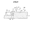
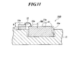
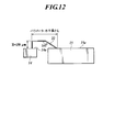
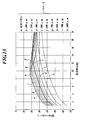
- Sectional drawing which shows the principal part of the optical module which concerns on 3rd Embodiment. Sectional drawing which shows the principal part of the optical module which concerns on 4th Embodiment. Sectional drawing which shows the principal part of the optical module which concerns on 5th Embodiment. Explanatory drawing of the Example of 6th Embodiment. The graph which shows the comparison of the crosstalk between adjacent channels of a conventional model and a proposal model.
- FIG. 1 is a perspective view showing the main part of the optical module according to the first embodiment
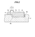
- FIG. 2 is a sectional view of FIG.
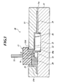
- FIG. 3 is a longitudinal sectional view showing a schematic configuration of the optical module.
- 4A is a perspective view showing the entire optical module
- FIG. 4B is an enlarged view showing one of a plurality of optical fibers used in the optical module
- FIG. 4C is a surface emitting semiconductor laser element of a laser diode array used in the optical module.
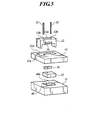
- 5 is an exploded perspective view showing a schematic configuration of the optical module
- FIG. 6 is a perspective view showing an optical connector portion of the optical module
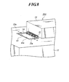
- FIG. 7 is an external connector (multi-fiber ferrule-type connector) connected to the optical connector portion of the optical module. It is a perspective view which shows the state which mounted
- the optical module 10 is an optical module that transmits optical signals in parallel through a plurality of optical fibers.
- the optical module 10 includes a substrate 11 having an electrode pattern (not shown), a plurality of optical elements arranged in alignment on the electrode pattern, and the electrode pattern.
- An electronic device mounted and electrically connected to the plurality of optical devices.
- the substrate 11 is a ceramic substrate.
- the plurality of optical elements are constituted by a laser diode array 14 having a plurality of surface-emitting type semiconductor laser elements (optical elements) arranged in a line.
- reference numeral 14 a indicates each light emitting portion (opening) of the plurality of surface emitting semiconductor laser elements in the laser diode array 14.
- a surface emitting semiconductor laser element as an optical element is a VCSEL (Vertical Cavity Surface Emitting Laser) that emits light (optical signal 23) in a direction perpendicular to a substrate surface.
- the electronic element is a driver IC 15 that drives a plurality of surface emitting semiconductor laser elements of the laser diode array 14.
- the optical module 10 is characterized by a plurality of wires (transmission lines) that respectively transmit signals between a plurality of surface emitting semiconductor laser elements of the laser diode array 14 and the driver IC 15.
- the laser diode array 14 and the driver IC are arranged on the substrate 11 so that the length 22 is the shortest.
- the driver IC 15 is mounted on the substrate 11 so that the surface (surface) 14a of the laser diode array 14 and the surface (surface) 15a of the driver IC 15 have the same height so that the wire length is minimized. It arrange
- the wall surface 40a of the recess 40 is made substantially vertical so that the laser diode array 14 and the driver IC 15 can be arranged close to each other and the plurality of wires 22 are shortened.
- the laser diode array 14 is disposed on the substrate 11 at a position close to the wall surface 40a, and the driver IC 15 is disposed in the recess 40 at a position close to the wall surface 40a.
- the laser diode array 14 is mounted on the surface 11a of the substrate 11 by being bonded with, for example, a die attach agent.
- a part of the driver IC 15 is accommodated in the recess 40 of the substrate 11, and is mounted on the bottom surface of the recess 40 by, for example, bonding with a die attach agent.
- the recess 40 is a rectangular hole having a substantially vertical wall surface 40a.
- the laser diode array 14 is disposed on the surface 11a of the substrate so that the end surface thereof is close to the wall surface 40a.
- the driver IC 15 is disposed on the bottom surface of the recess 40 so that the end surface thereof is close to the wall surface 40a.
- the laser diode array 14 and the driver IC 15 are arranged on the substrate 11 at close positions.
- the driver IC 15 and the plurality of surface-emitting semiconductor laser elements of the laser diode array 14, that is, the electrodes on the surface 15 a of the driver IC 15 and the electrodes of the surface-emitting semiconductor laser elements on the surface 14 a of the laser diode array 14. are directly electrically connected by a plurality of wires 22 as transmission lines (see FIGS. 1, 2 and 4C).
- the plurality of surface emitting semiconductor laser elements of the driver IC 15 and the laser diode array 14 are electrically connected to each other by the plurality of wires 22 without using the wiring on the SiOB as in the conventional technique.
- a modulation signal is input from the driver IC 15 to each surface emitting semiconductor laser element of the laser diode array 14 via each bonding wire 22, and from each surface emitting semiconductor laser element of the laser diode array 14 according to the modulation signal.
- a modulated optical signal 23 is emitted.
- the driver IC 15 and the electrode pattern of the substrate 11 are electrically connected by a plurality of bonding wires (not shown).
- reference numeral 22a denotes a ball fused to the electrode of each surface emitting semiconductor laser element.
- the optical module 10 further includes an optical connector portion 12, a cover 13, and two guide pins 32, as shown in FIGS.
- the optical connector unit 12 holds a plurality of optical fibers 16 aligned in a row (in a direction perpendicular to the paper surface in FIG. 3).
- the optical connector portion 12 is active-aligned so that the centers (core centers) of the one end portions 16a (see FIG. 4B) of the plurality of optical fibers 16 coincide with the centers of the light emitting portions 14a of the laser diode array 14.
- the substrate 11 is fixed on the surface 11a.
- each outgoing light (optical signal 23) from each light emitting part 14a of the laser diode array 14 is optically coupled to one end part 16a of the corresponding optical fiber of the plurality of optical fibers 16, respectively.
- the optical connector portion 12 has left and right side wall portions 17 as shown in FIG. Lower end surfaces 17a of the side wall portions 17 are slidably in contact with the surface 11a of the substrate 11, respectively.
- the optical connector portion 12 is moved two-dimensionally within the surface 11a of the substrate 11 so that the center of each end portion 16a of the plurality of optical fibers 16 and the center of each light emitting portion 14a of the laser diode array 14 coincide.
- the lower end surfaces 17a of the side wall portions 17 of the optical connector portion 12 are fixed to the surface 11a of the substrate 11 by bonding or the like.
- the optical connector unit 12 includes a plurality of fiber holding holes 12a aligned in a line in which the plurality of optical fibers 16 are fitted, and two fiber holding holes 12a provided on both sides of the fiber holding holes 12a. And a guide pin hole 12b. Two guide pins 32 can be fitted into the two guide pin holes 12b.
- the two through holes of a multi-fiber optical fiber connector (hereinafter referred to as an MT connector) 30 which is an external connector shown in FIG.
- the cover 13 has an opening 13a for mounting the optical connector portion 12, and covers the entire substrate 11 such as the laser diode array 14, the driver IC 15 and the like. Fixed by bonding or the like.
- the cover 13 is made of a material having high thermal conductivity, for example, an alloy of Cu (copper) and W (tungsten).
- the gap between the side surface of the optical connector portion 12 and the opening portion 13a of the cover 13 is filled with a resin 18 such as a resin sealant or an adhesive as shown in FIG.
- a gap (space) between the driver IC 15 and the cover 13 is filled with a silicone gel 19 having thermal conductivity and insulating properties as a sealing agent.
- a transparent silicone gel 20 is filled as a sealant in a space between one end portion 16a of the plurality of optical fibers 16 and each light emitting portion 14a of the laser diode array 14.
- the driver IC 15 is disposed in the recess 40 so that the surface (surface) 14a of the laser diode array 14 and the surface (surface) 15a of the driver IC 15 have the same height so that the wire length is minimized. Since the surface 14a and the surface (surface) 15a are directly electrically connected by a plurality of wires 22 as transmission lines, respectively, the wire length L (see FIG. 2) of the plurality of wires 22 is shortened. Thereby, in the optical module in which the laser diode array 14 and the driver IC 15 are mounted by wire bonding, crosstalk between adjacent wires 22 can be reduced.
- Active alignment is performed so that the plurality of optical fibers 16 and the plurality of surface emitting semiconductor laser elements of the laser diode array 14 are optically coupled by adjusting the position of the optical connector 12 on the substrate 11 two-dimensionally. It is configured to do. That is, by this active alignment, the centers of the one end portions 16a of the plurality of optical fibers 16 and the centers of the light emitting portions 14a of the laser diode array 14 are matched.
- the wire length L of the plurality of wires 22 that electrically connect the plurality of surface emitting semiconductor laser elements of the laser diode array 14 and the driver IC 15 can be shortened, and crosstalk between adjacent wires 22 can be reduced. Can be reduced.
- the wall surface 40a of the recess 40 is substantially vertical, the laser diode array 14 and the driver IC 15 can be arranged close to each other, and the plurality of wires 22 can be shortened. Thereby, crosstalk between adjacent wires 22 can be reduced, and high-speed parallel optical transmission can be realized.
- An optical module 10A according to the second embodiment will be described with reference to FIG.
- the driver IC 15 is mounted on the electrode pattern of the substrate 11 by wire bonding.
- the optical module 10A according to the second embodiment has the following configuration.
- the driver IC 15 is flip-chip mounted on the electrode pattern of the substrate 11.
- the laser diode array 14 is placed in the recess 41 formed on the substrate 11 so that the surface 14a of the laser diode array 14 and the surface 11a of the substrate 11 have the same height so that the wire length is the shortest. Has been placed.
- the plurality of surface emitting semiconductor laser elements of the laser diode array 14 and the wiring on the substrate 11 to which the driver IC 15 is electrically connected are electrically connected by a plurality of wires 22.
- Other configurations are the same as those of the optical module 10 of the first embodiment.
- the length of the plurality of wires (transmission lines) 22 that respectively transmit signals between the plurality of surface emitting semiconductor laser elements of the laser diode array 14 and the driver IC 15 is minimized.
- the entire laser diode array 14 is housed in the recess 41 of the substrate 11 and mounted on the bottom surface of the recess 41 by, for example, bonding with a die attach agent.
- the recess 41 is a rectangular hole having a substantially vertical wall surface 41 a and having a depth substantially the same as the height of the laser diode array 14.
- the laser diode array 14 is disposed in the recess 41 so that its end face is close to the wall surface 41a.
- the driver IC 15 is mounted on the electrode pattern of the substrate 11 so that its end face is close to the wall surface 41a. In this way, the laser diode array 14 and the driver IC 15 are arranged on the substrate 11 at close positions.
- the plurality of surface emitting semiconductor laser elements of the laser diode array 14 and the wiring (part of the electrode pattern) to which the driver IC 15 is electrically connected are electrically connected by a plurality of wires 22, respectively.
- a transmission line for transmitting a signal between the plurality of surface emitting semiconductor laser elements of the laser diode array 14 and the driver IC 15 includes a wiring on the substrate 11 to which the driver IC 15 is electrically connected and a plurality of wiring lines. It is composed of a wire 22.
- each surface emitting semiconductor laser element of the laser diode array 14 is a VCSEL (Vertical Cavity Surface) that emits light (optical signal 23) from the surface 14a in a direction perpendicular to the substrate surface.
- VCSEL Vertical Cavity Surface
- Emitting Laser a backside emitting VCSEL that emits light (optical signal 23) from the backside 14b in a direction perpendicular to the substrate surface. It is.
- This optical module 10B has the following configuration.
- Each surface emitting semiconductor laser element of the laser diode array 14 is a back surface emitting VCSEL.
- the laser diode array 14 having a plurality of surface emitting semiconductor laser elements is flip-chip mounted on the substrate 11.
- the driver IC 1 is disposed in the recess 42 formed on the substrate 11 so that the surface 15a of the driver IC 15 and the surface 11a of the substrate 11 have the same height so that the wire length is the shortest. .
- the driver IC 15 and the plurality of wirings (a part of the electrode pattern) on the substrate 11 to which the plurality of surface emitting semiconductor laser elements of the laser diode array 14 are electrically connected are electrically connected by the plurality of wires 22, respectively. It is connected.
- Other configurations are the same as those of the optical module 10 of the first embodiment.
- the length of the plurality of wires (transmission lines) 22 that respectively transmit signals between the plurality of surface emitting semiconductor laser elements of the laser diode array 14 and the driver IC 15 is minimized.
- the driver IC 15 is entirely housed in the recess 42 of the substrate 11 and mounted on the bottom surface of the recess 42 by, for example, bonding with a die attach agent.
- the recess 42 is a rectangular hole having a substantially vertical wall surface 42a and having a depth substantially the same as the height of the driver IC 15.
- the driver IC 15 is disposed in the recess 42 so that its end face is close to the wall surface 42a.
- the laser diode array 14 is mounted on the electrode pattern of the substrate 11 so that its end face is close to the wall surface 42a.
- a wiring (a part of the electrode pattern) to which the plurality of surface emitting semiconductor laser elements of the laser diode array 14 are electrically connected and the driver IC 15 are electrically connected by a plurality of wires 22, respectively.
- the following operational effects are exhibited in addition to the operational effects exhibited by the first embodiment.
- O Crosstalk in adjacent transmission lines can be reduced in an optical module in which a laser diode array 14 having a plurality of surface emitting semiconductor laser elements, which are backside emitting VCSELs, is flip-chip mounted on a substrate 11.
- the transmission line for transmitting signals between the plurality of surface emitting semiconductor laser elements of the laser diode array 14 and the driver IC 15 is electrically connected to the plurality of surface emitting semiconductor laser elements of the laser diode array 14.
- a plurality of wirings (part of the electrode pattern) on the connected substrate 11 and a plurality of wires 22 are configured.
- the surface 14a of the laser diode array 14 and the surface 15a of the driver IC 15 have the same height so that the wire length is the shortest, and the length of the plurality of wires 22 is increased. The shortest.
- this optical module 10C has the following configuration.
- the driver IC 15 is disposed in the recess 43 formed on the substrate 11.
- the electrodes on the surface 14a of the laser diode array 14 and the electrodes on the surface 15a of the driver IC 15 are electrically connected directly by a plurality of wires 22, respectively.
- the surface 15 a of the driver IC 15 is made higher than the surface 14 a of the laser diode array 14 within a range that does not cause an electrical short at each end of the plurality of wires 22.
- Other configurations are the same as those of the optical module 10 of the first embodiment.
- the following functions and effects can be obtained in addition to the functions and effects exhibited by the first embodiment.
- each wire can be made as short as possible without causing an electrical short at each end of the plurality of wires 22. Thereby, crosstalk between adjacent wires 22 can be reduced, and high-speed parallel optical transmission can be realized.
- the wire length of the plurality of wires 22 can be made as short as possible without causing an electrical short at both ends of the wires 22.
- An optical module 10D according to the fifth embodiment will be described with reference to FIG.
- the surface 4a of the laser diode array 14 and the surface 15a of the driver IC 15 have the same height so that the wire length is the shortest, and the length of the plurality of wires 22 is increased. The shortest.
- this optical module 10C has the following configuration.
- the driver IC 15 is disposed in the recess 44 formed on the substrate 11.
- the electrodes on the surface 14a of the laser diode array 14 and the electrodes on the surface 15a of the driver IC 15 are electrically connected directly by a plurality of wires 22, respectively.
- the surface 14a of the laser diode array 14 is made higher than the surface 15a of the driver IC 15 within a range that does not cause an electrical short at each end of the plurality of wires 22.
- Other configurations are the same as those of the optical module 10 of the first embodiment.
- the following operational effects are exhibited in addition to the operational effects exhibited by the first embodiment.
- each wire can be made as short as possible without causing an electrical short at each end of the plurality of wires 22. Thereby, crosstalk between adjacent wires 22 can be reduced, and high-speed parallel optical transmission can be realized.
- the wire length of the plurality of wires 22 could be made as short as possible without causing an electrical short at both ends of the wires 22.
- FIG. 1 is a perspective view showing a main part of an optical module according to a sixth embodiment
- FIG. 2 is a cross-sectional view of FIG.
- FIG. 3 is a longitudinal sectional view showing a schematic configuration of the optical module.
- 4A is a perspective view showing the entire optical module
- FIG. 4B is an enlarged view showing one of a plurality of optical fibers used in the optical module
- FIG. 4C is a surface emitting semiconductor laser element of a laser diode array used in the optical module.
- 5 is an exploded perspective view showing a schematic configuration of the optical module
- FIG. 6 is a perspective view showing an optical connector portion of the optical module
- FIG. 7 is an external connector (multi-fiber ferrule-type connector) connected to the optical connector portion of the optical module. It is a perspective view which shows the state which mounted
- the optical module 10 is an optical module that transmits optical signals in parallel using a plurality of optical fibers.
- the optical module 10 includes a substrate 11 having an electrode pattern (not shown), a plurality of optical elements arranged in alignment on the electrode pattern, and the electrode pattern.
- An electronic device mounted and electrically connected to the plurality of optical devices.
- the substrate 11 is a ceramic substrate.
- the plurality of optical elements are constituted by a laser diode array 14 having a plurality of surface-emitting type semiconductor laser elements (optical elements) arranged in a line.
- reference numeral 14 a indicates each light emitting portion (opening portion) of a plurality of surface emitting semiconductor laser elements in the laser diode array 14.
- a surface emitting semiconductor laser element as an optical element is a VCSEL (Vertical Cavity Surface Emitting Laser) that emits light (optical signal 23) in a direction perpendicular to a substrate surface.
- the electronic element is a driver IC 15 that drives a plurality of surface emitting semiconductor laser elements of the laser diode array 14.
- the laser diode array 14 and the driver IC 15 are disposed on the substrate 11 at positions close to each other.
- the laser diode array 14 is mounted on the surface 11a of the substrate 11 by being bonded with, for example, a die attach agent.
- a part of the driver IC 15 is accommodated in the recess 40 of the substrate 11, and is mounted on the bottom surface of the recess 40 by, for example, bonding with a die attach agent.
- the recess 40 is a rectangular hole having a substantially vertical wall surface 40a.
- the laser diode array 14 is disposed on the surface 11a of the substrate so that the end surface thereof is close to the wall surface 40a.
- the driver IC 15 is disposed on the bottom surface of the recess 40 so that the end surface thereof is close to the wall surface 40a. In this way, the laser diode array 14 and the driver IC 15 are arranged on the substrate 11 at close positions.
- the electrodes on the surface 15a of the driver IC 15 and the electrodes of the surface emitting semiconductor laser elements on the surface 14a of the laser diode array 14 are electrically connected directly by a plurality of wires 22, respectively (FIG. 1). FIG. 2 and FIG. 4C).
- the plurality of surface emitting semiconductor laser elements of the driver IC 15 and the laser diode array 14 are electrically connected to each other by the plurality of wires 22 without using the wiring on the SiOB as in the conventional technique.
- a modulation signal is input from the driver IC 15 to each surface emitting semiconductor laser element of the laser diode array 14 via each bonding wire 22, and from each surface emitting semiconductor laser element of the laser diode array 14 according to the modulation signal.
- a modulated optical signal 23 is emitted.
- the driver IC 15 and the electrode pattern of the substrate 11 are electrically connected by a plurality of bonding wires (not shown).
- reference numeral 22a denotes a ball mounted on an electrode of each surface emitting semiconductor laser element.
- the optical module 10 further includes an optical connector portion 12, a cover 13, and two guide pins 32, as shown in FIGS.
- the optical connector unit 12 holds a plurality of optical fibers 16 aligned in a row (in a direction perpendicular to the paper surface in FIG. 3).
- the optical connector portion 12 is active-aligned so that the centers (core centers) of the one end portions 16a (see FIG. 4B) of the plurality of optical fibers 16 coincide with the centers of the light emitting portions 14a of the laser diode array 14.
- the substrate 11 is fixed on the surface 11a.
- each outgoing light (optical signal 23) from each light emitting part 14a of the laser diode array 14 is optically coupled to one end part 16a of the corresponding optical fiber of the plurality of optical fibers 16, respectively.
- the optical connector portion 12 has left and right side wall portions 17 as shown in FIG. Lower end surfaces 17a of the side wall portions 17 are slidably in contact with the surface 11a of the substrate 11, respectively.
- the optical connector portion 12 is moved two-dimensionally within the surface 11a of the substrate 11 so that the center of each end portion 16a of the plurality of optical fibers 16 and the center of each light emitting portion 14a of the laser diode array 14 coincide.
- the lower end surfaces 17a of the side wall portions 17 of the optical connector portion 12 are fixed to the surface 11a of the substrate 11 by bonding or the like.
- the optical connector unit 12 includes a plurality of fiber holding holes 12a aligned in a line in which the plurality of optical fibers 16 are fitted, and two fiber holding holes 12a provided on both sides of the fiber holding holes 12a. And a guide pin hole 12b. Two guide pins 32 can be fitted into the two guide pin holes 12b.
- the two guide pins 32 can be fitted with two through holes of the MT connector 30 which is an external connector shown in FIG.
- the core center of each optical fiber of the multi-core optical fiber (multi-fiber tape optical fiber) 31 held by the MT connector 30 by fitting the two through holes of the MT connector 30 with the two guide pins 32 and 32, respectively.
- the MT connector 30 is attached to the optical connector portion 12 as shown in FIG. 7 in a state where the core centers of the plurality of optical fibers 16 held by the optical connector portion 12 coincide with each other.
- the cover 13 has an opening 13a for mounting the optical connector portion 12, and covers the entire substrate 11 such as the laser diode array 14, the driver IC 15 and the like. Fixed by bonding or the like.
- the cover 13 is made of a material having high thermal conductivity, for example, an alloy of Cu (copper) and W (tungsten).
- the gap between the side surface of the optical connector portion 12 and the opening portion 13a of the cover 13 is filled with a resin 18 such as a resin sealant or an adhesive as shown in FIG.
- a gap (space) between the driver IC 15 and the cover 13 is filled with a silicone gel 19 having thermal conductivity and insulating properties as a sealing agent.
- a transparent silicone gel 20 is filled as a sealant in a space between one end portion 16a of the plurality of optical fibers 16 and each light emitting portion 14a of the laser diode array 14.
- the laser diode array 14 and the driver IC 15 are arranged at positions close to each other on the substrate 11, a plurality of transmission line lengths for electrically connecting the plurality of surface emitting semiconductor laser elements of the laser diode array 14 and the driver IC 15
- the crosstalk between adjacent transmission lines can be reduced. Thereby, high-speed parallel optical transmission can be realized.
- Active alignment is performed so that the plurality of optical fibers 16 and the plurality of surface emitting semiconductor laser elements of the laser diode array 14 are optically coupled by adjusting the position of the optical connector 12 on the substrate 11 two-dimensionally. It is configured to do. That is, by this active alignment, the centers of the one end portions 16a of the plurality of optical fibers 16 and the centers of the light emitting portions 14a of the laser diode array 14 are matched. This eliminates the need for SiOB for passive alignment as in the prior art described above, and allows the laser diode array 14 and the driver IC 15 to be disposed on the substrate 11 in close proximity.
- the length (transmission line length) of the plurality of wires 22 that electrically connect the plurality of surface emitting semiconductor laser elements of the laser diode array 14 and the driver IC 15 can be reduced, and between adjacent transmission lines. Crosstalk can be reduced.
- the wire length L (see FIG. 2) of the plurality of wires 22 is short. Become. Thereby, in the optical module in which the driver IC 15 and the laser diode array 14 are mounted by wire bonding, crosstalk between adjacent wires can be reduced.
- each of the plurality of wires 22 has a wire horizontal length (wire length) L of 500 ⁇ m or less.
- each wire 22 has a shape shown in FIG. Further, the surface 14a of the laser diode array 14 and the surface 15a of the driver IC 15 are set to have the same height. The pitch between the plurality of wires 22 was 250 ⁇ m.
- the graph in FIG. 13 shows the result of comparing the crosstalk between adjacent wires (between adjacent channels) between the conventional model and the proposed model.
- the conventional model is an optical module in which a plurality of optical elements are connected to wiring on the SiOB by wires as in the prior art, and the wiring and electronic elements are connected by wires.
- the proposed model is the optical module 10 described in the sixth embodiment.
- the horizontal axis represents the frequency (GHz) of the modulation signal transmitted from the driver IC to each surface emitting semiconductor laser element via the wire 22, and the vertical axis represents the S parameter (Scattering representing the crosstalk component between the channels. Parameter).
- a curve a indicates the S parameter when the frequency of the modulation signal is changed in the conventional model. From this curve a, it can be seen that in the conventional model, the crosstalk between adjacent wires (channels) cannot be suppressed to 30 dB or less in a transmission band exceeding 3 GHz.
- the driver IC 15 is mounted on the electrode pattern of the substrate 11 by wire bonding.
- the driver IC 15 is flip-chip mounted on the electrode pattern of the substrate 11, as shown in FIG.
- the entire laser diode array 14 is accommodated in the recess 41 of the substrate 11 and mounted on the bottom surface of the recess 41 by, for example, bonding with a die attach agent.
- the recess 41 is a rectangular hole having a substantially vertical wall surface 41 a and having a depth substantially the same as the height of the laser diode array 14.
- the laser diode array 14 is disposed in the recess 41 so that its end face is close to the wall surface 41a.
- the driver IC 15 is mounted on the electrode pattern of the substrate 11 so that its end face is close to the wall surface 41a. In this way, the laser diode array 14 and the driver IC 15 are arranged on the substrate 11 at close positions.
- the plurality of surface emitting semiconductor laser elements of the laser diode array 14 and the wiring (part of the electrode pattern) to which the driver IC 15 is electrically connected are electrically connected by a plurality of wires 22, respectively.
- a plurality of transmission lines are respectively configured by a plurality of wires 22 that electrically connect the plurality of surface emitting semiconductor laser elements of the laser diode array 14 and the driver IC 15 respectively, and wiring that is electrically connected to the driver IC 15.
- the length of the plurality of transmission lines is shortened. As a result, in the optical module in which the driver IC 15 is flip-chip mounted on the electrode pattern of the substrate 11, crosstalk in adjacent transmission lines can be reduced.
- optical module 10B according to an eighth embodiment will be described with reference to FIG.
- each surface emitting semiconductor laser element of the laser diode array 14 is a VCSEL (VerticalVerCavity Surface Emitting) that emits light (optical signal 23) from the surface side in a direction perpendicular to the substrate surface. Laser).
- each surface emitting semiconductor laser element of the laser diode array 14 used in the optical module 10G is a back emitting VCSEL that emits light (optical signal 23) from the back side in a direction perpendicular to the substrate surface. is there.
- the laser diode array 14 is mounted on the electrode pattern of the substrate 11 by flip chip mounting.
- the entire driver IC 15 is housed in the recess 42 of the substrate 11 and mounted on the bottom surface of the recess 42 by, for example, bonding with a die attach agent.
- the recess 42 is a rectangular hole having a substantially vertical wall surface 42a and having a depth substantially the same as the height of the driver IC 15.
- the driver IC 15 is disposed in the recess 42 so that its end face is close to the wall surface 42a.
- the laser diode array 14 is mounted on the electrode pattern of the substrate 11 so that its end face is close to the wall surface 42a.
- the laser diode array 14 and the driver IC 15 are arranged on the substrate 11 at close positions. Then, a plurality of wirings (a part of the electrode pattern) to which the plurality of surface emitting semiconductor laser elements of the laser diode array 14 are electrically connected and the driver IC 15 are electrically connected by a plurality of wires 22, respectively. Yes.
- Other configurations are the same as those of the optical module 10 of the sixth embodiment.
- this invention can also be changed and embodied as follows.
- the optical modules 10, 10A, 10B, 10C, and 10D configured as the transmission-side optical modules have been described, but the present invention is not limited to this.
- a photodiode array having a plurality of photodiode elements (optical elements) arranged in a line is used instead of the laser diode array 14.
- the present invention is also applied to an optical module configured as a receiving-side optical module using an amplifier IC having a TIA (Transimpedance Amplifier) function that converts the output current of each photodiode into a voltage and amplifies it instead of the driver IC 15. Is applicable.
- TIA Transimpedance Amplifier
- An optical module in which a plurality of surface emitting semiconductor laser elements (optical elements) are arranged in a line instead of the laser diode array 14 or a plurality of photodiodes (optical elements) instead of the photodiode array The present invention can also be applied to an optical module in which the components are mounted in a line.
- It can be used in the field of optical communication, and can be applied to an optical module that transmits optical signals in parallel using an optical fiber.
- optical module 11 substrate 11a: surface 12: optical connector part 13: cover 14: laser diode array 14a: surface 15: driver IC (electronic element) 15a: surface 16: optical fiber 16a: one end 22: wire 23: optical signal 30: multi-core optical fiber connector (MT connector) 31: Multi-core optical fiber (multi-fiber tape optical fiber) 40, 41, 42, 43, 44: recessed portions 40a, 41a, 42a, 43a, 44a: wall surfaces
Landscapes
- Physics & Mathematics (AREA)
- General Physics & Mathematics (AREA)
- Optics & Photonics (AREA)
- Condensed Matter Physics & Semiconductors (AREA)
- Electromagnetism (AREA)
- Optical Couplings Of Light Guides (AREA)
- Semiconductor Lasers (AREA)
Abstract
Description
前記基板の電極パターン上に実装された複数の光素子と、前記基板の電極パターン上に実装され、前記複数の光素子と電気的に接続された電子素子と、を備え、前記複数の光素子と前記電子素子が前記基板上で近接した位置に配置されていることを特徴とする。この構成によれば、複数の発光素子と電子素子を電気的に接続する複数の伝送線路長が短くなり、隣接する伝送線路間でのクロストークを低減することができる。これにより、高速並列光伝送を実現することができる。
(第1実施形態)
第1実施形態に係る光モジュールを図1乃至図7に基づいて説明する。
○レーザーダイオードアレイ14の複数の面発光型半導体レーザ素子とドライバIC15との間で信号をそれぞれ伝送する複数のワイヤ(伝送線路)22の長さが最短になるように、レーザーダイオードアレイ14とドライバICが基板11上に配置されている。これにより、隣接するワイヤ22間でのクロストークを低減することができ、高速並列光伝送を実現することができる。
(第2実施形態)
第2実施形態に係る光モジュール10Aを図8に基づいて説明する。
その他の構成は、上記第1実施形態の光モジュール10と同様である。
(第3実施形態)
第3実施形態に係る光モジュール10Bを図9に基づいて説明する。
・レーザーダイオードアレイ14の各面発光型半導体レーザ素子は、裏面発光型VCSELである。
その他の構成は、上記第1実施形態の光モジュール10と同様である。
(第4実施形態)
第4実施形態に係る光モジュール10Cを図10に基づいて説明する。
その他の構成は、上記第1実施形態の光モジュール10と同様である。
上記光モジュール10Cにおいて、複数のワイヤ22として、φ25μmの金ワイヤを使用した。また、ワイヤ22のループ高さをHとし、レーザーダイオードアレイ14の表面14aからドライバIC15の表面15aまでの高さをHDとすると、HD=H-(25μm×2)となるように、ドライバIC15の表面15aをレーザーダイオードアレイ14の表面14aより高くした。レーザーダイオードアレイ14の表面14a上にボール22aを実装した。
(第5実施形態)
第5実施形態に係る光モジュール10Dを図11に基づいて説明する。
その他の構成は、上記第1実施形態の光モジュール10と同様である。
上記光モジュール10Dにおいて、複数のワイヤ22として、φ25μmの金ワイヤを使用した。また、ワイヤ22のループ高さをHとし、レーザーダイオードアレイ14の表面14aからドライバIC15の表面15aまでの高さをHDとすると、HD=H-(25μm×2)となるように、レーザーダイオードアレイ14の表面14aをドライバIC15の表面15aより高くした。ドライバIC15の表面15a上にボール22aを実装した。
第6実施形態に係る光モジュールの構成は、図1乃至図7に基づいて説明した第1実施形態に係る光モジュールと同様である。
第6実施形態に係る光モジュールを図1乃至図7、図12、図13に基づいて説明する。
○レーザーダイオードアレイ14とドライバIC15が基板11上で近接した位置に配置されているので、レーザーダイオードアレイ14の複数の面発光型半導体レーザ素子とドライバIC15を電気的に接続する複数の伝送線路長が短くなり、隣接する伝送線路間でのクロストークを低減することができる。これにより、高速並列光伝送を実現することができる。
上記第6実施形態において、複数のワイヤ22のワイヤ水平方向長さ(ワイヤ長)Lをそれぞれ500μm以下にした。本実施例では、各ワイヤ22に、図12に示す形状のものを用いた。また、レーザーダイオードアレイ14の表面14aとドライバIC15の表面15aを同一の高さになるようにしている。また、複数のワイヤ22間のピッチを250μmとした。
第7実施形態に係る光モジュールの構成は、図8に基づいて説明した第2実施形態に係る光モジュールと同様である。
第7実施形態に係る光モジュール10Aを図8に基づいて説明する。
このような構成を有する第7実施形態によれば、上記第6実施形態の奏する作用効果に加えて、以下の作用効果を奏する。
第8実施形態に係る光モジュールの構成は、図9に基づいて説明した第3実施形態に係る光モジュールと同様である。
第8実施形態に係る光モジュール10Bを図9に基づいて説明する。
その他の構成は、上記第6実施形態の光モジュール10と同様である。
・上記各実施形態では、送信側光モジュールとして構成した光モジュール10,10A,10B,10C,10Dについて説明したが、本発明はこれに限定されない。光モジュール10,10A,10B、10C,10Dにおいて、レーザーダイオードアレイ14に代えて一列に整列された複数のフォトダイオード素子(光素子)を有するフォトダイオードアレイを用いる。そして、ドライバIC15に代えて、各フォトダイオードの出力電流を電圧に変換して増幅するTIA(Transimpedance Amplifier)機能を備えた増幅用ICを用いて受信側光モジュールとして構成した光モジュールにも本発明は適用可能である。
11:基板
11a:表面
12:光コネクタ部
13:カバー
14:レーザーダイオードアレイ
14a:表面
15:ドライバIC(電子素子)
15a:表面
16:光ファイバ
16a:一端部
22:ワイヤ
23:光信号
30:多心光ファイバコネクタ(MTコネクタ)
31:多心光ファイバ(多心テープ光ファイバ)
40,41,42,43,44:凹部
40a,41a,42a,43a,44a:壁面
Claims (18)
- 複数の光ファイバで光信号を並列伝送する光モジュールであって、
電極パターンを有する基板と、
前記基板の電極パターン上に実装された複数の光素子と、
前記基板の電極パターン上に実装され、前記複数の光素子と電気的に接続された電子素子と、を備え、
前記複数の光素子と前記電子素子との間で信号を伝送する伝送線路の長さが最短になるように、前記複数の光素子と前記電子素子が前記基板上に配置されていることを特徴とする光モジュール。 - 前記複数の光ファイバを保持し、前記複数の光ファイバと前記複数の光素子とがそれぞれ光結合する位置で前記基板に固定される光コネクタ部をさらに備え、
前記光コネクタ部は、前記基板上で二次元的に位置調整可能であることを特徴とする請求項1に記載の光モジュール。 - ワイヤ長が最短になるように前記複数の光素子の面と前記電子素子の面とが同程度の高さになるように、前記電子素子が前記基板上に形成された凹部内に配置され、
前記複数の光素子の面と前記電子素子の面とが、前記伝送線路としての複数のワイヤでそれぞれ直接、電気的に接続されていることを特徴とする請求項1又は2に記載の光モジュール。 - 前記凹部は略垂直な壁面を有し、
前記複数の光素子は、前記壁面に近接した位置でかつ前記壁面に沿って整列するように前記基板上に配置され、
前記電子素子は前記壁面に近接した位置で前記凹部内に配置されていることを特徴とする請求項3に記載の光モジュール。 - 前記電子素子が前記基板上にフリップチップ実装され、
ワイヤ長が最短になるように前記複数の光素子の面と前記基板の面とが同程度の高さになるように、前記複数の光素子が前記基板上に形成された凹部内に配置され、
前記複数の光素子と、前記電子素子が電気的に接続された前記基板上の配線とが複数のワイヤで電気的に接続されていることを特徴とする請求項1又は2に記載の光モジュール。 - 前記複数の光素子はそれぞれ裏面側から光を出射する面発光型半導体レーザ素子であり、
前記複数の光素子は前記基板上にフリップチップ実装され、
ワイヤ長が最短になるように前記電子素子の表面と前記基板の表面とが同程度の高さになるように、前記電子素子が前記基板上に形成された凹部内に配置され、
前記電子素子と、前記複数の光素子が電気的に接続された前記基板上の配線とが複数のワイヤで電気的に接続されていることを特徴とする請求項1又は2に記載の光モジュール。 - 前記電子素子が前記基板上に形成された凹部内に配置され、
前記複数の光素子の面と前記電子素子の面とが、前記伝送線路としての複数のワイヤでそれぞれ直接、電気的に接続されており、
前記複数のワイヤの各両端で電気的ショートを起こさない範囲で、前記電子素子の面を前記複数の光素子の面より高くしたことを特徴とする請求項1又は2に記載の光モジュール。 - 前記電子素子が前記基板上に形成された凹部内に配置され、
前記複数の光素子の面と前記電子素子の面とが、前記伝送線路としての複数のワイヤでそれぞれ直接、電気的に接続されており、
前記複数のワイヤの各両端で電気的ショートを起こさない範囲で、前記複数の光素子の面を前記電子素子の面より高くしたことを特徴とする請求項1又は2に記載の光モジュール。 - 前記光素子としての複数の面発光型半導体レーザ素子と、前記複数の面発光型半導体レーザ素子を駆動する前記電子素子としてのドライバICとを備え、前記複数の面発光型半導体レーザ素子からそれぞれ出射される光信号を前記複数の光ファイバを介して外部へ並列伝送する送信側光モジュールとして構成したことを特徴とする請求項1乃至8のいずれか一つに記載の光モジュール。
- 前記光素子としての複数のフォトダイオードと、前記フォトダイオードの出力電流を電圧に変換して増幅する機能を有する前記電子素子としての増幅用ICとを備え、外部から前記複数の光ファイバを介して並列伝送された光信号を前記複数のフォトダイオードで受光して電気信号に変換する受信側光モジュールとして構成したことを特徴とする請求項1乃至8のいずれか一つに記載の光モジュール。
- 複数の光ファイバで光信号を並列伝送する光モジュールであって、
電極パターンを有する基板と、
前記基板の電極パターン上に実装された複数の光素子と、
前記基板の電極パターン上に実装され、前記複数の光素子と電気的に接続された電子素子と、を備え、
前記複数の光素子と前記電子素子が前記基板上で近接した位置に配置されていることを特徴とする光モジュール。 - 前記複数の光ファイバを保持し、前記複数の光ファイバと前記複数の光素子とがそれぞれ光結合する位置で前記基板に固定される光コネクタ部をさらに備え、
前記光コネクタ部は、前記基板上で二次元的に位置調整可能であることを特徴とする請求項11に記載の光モジュール。 - 前記電子素子と前記複数の光素子が複数のワイヤでそれぞれ直接、電気的に接続されていることを特徴とする請求項11又は12に記載の光モジュール。
- 前記複数のワイヤのワイヤ水平方向長さをそれぞれ500μm以下にしたことを特徴とする請求項13に記載の光モジュール。
- 前記電子素子が前記基板上にフリップチップ実装され、前記複数の光素子と、前記電子素子が電気的に接続された前記基板上の配線とが複数のワイヤで電気的に接続されていることを特徴とする請求項11又は12に記載の光モジュール。
- 前記複数の光素子と電子素子をそれぞれ電気的に接続する前記複数のワイヤと配線とで構成される複数の伝送線路長を500μm以下にしたことを特徴とする請求項15に記載の光モジュール。
- 前記光素子としての複数の面発光型半導体レーザ素子と、前記複数の面発光型半導体レーザ素子を駆動する前記電子素子としてのドライバICとを備え、前記複数の面発光型半導体レーザ素子からそれぞれ出射される光信号を前記複数の光ファイバを介して外部へ並列伝送する送信側光モジュールとして構成したことを特徴とする請求項11乃至16のいずれか一つに記載の光モジュール。
- 前記光素子としての複数のフォトダイオードと、前記フォトダイオードの出力電流を電圧に変換して増幅する機能を有する前記電子素子としての増幅用ICとを備え、外部から前記複数の光ファイバを介して並列伝送された光信号を前記複数のフォトダイオードで受光して電気信号に変換する受信側光モジュールとして構成したことを特徴とする請求項11乃至16のいずれか一つに記載の光モジュール。
Priority Applications (4)
| Application Number | Priority Date | Filing Date | Title |
|---|---|---|---|
| US12/863,194 US20110049334A1 (en) | 2008-01-16 | 2009-01-15 | Optical module |
| JP2009550036A JPWO2009090988A1 (ja) | 2008-01-16 | 2009-01-15 | 光モジュール |
| CN2009801023794A CN101911405B (zh) | 2008-01-16 | 2009-01-15 | 光模块 |
| EP09701495.5A EP2242152A4 (en) | 2008-01-16 | 2009-01-15 | Optical module |
Applications Claiming Priority (4)
| Application Number | Priority Date | Filing Date | Title |
|---|---|---|---|
| JP2008007443 | 2008-01-16 | ||
| JP2008007442 | 2008-01-16 | ||
| JP2008-007442 | 2008-01-16 | ||
| JP2008-007443 | 2008-01-16 |
Publications (1)
| Publication Number | Publication Date |
|---|---|
| WO2009090988A1 true WO2009090988A1 (ja) | 2009-07-23 |
Family
ID=40885374
Family Applications (1)
| Application Number | Title | Priority Date | Filing Date |
|---|---|---|---|
| PCT/JP2009/050448 Ceased WO2009090988A1 (ja) | 2008-01-16 | 2009-01-15 | 光モジュール |
Country Status (5)
| Country | Link |
|---|---|
| US (1) | US20110049334A1 (ja) |
| EP (1) | EP2242152A4 (ja) |
| JP (1) | JPWO2009090988A1 (ja) |
| CN (1) | CN101911405B (ja) |
| WO (1) | WO2009090988A1 (ja) |
Cited By (6)
| Publication number | Priority date | Publication date | Assignee | Title |
|---|---|---|---|---|
| JP4969711B2 (ja) * | 2010-08-31 | 2012-07-04 | 京セラ株式会社 | 光伝送体およびその製造方法、ならびに光伝送モジュール |
| JP2015212781A (ja) * | 2014-05-07 | 2015-11-26 | 住友電気工業株式会社 | 光学装置の製造方法、光学装置及び光学コネクタユニット |
| KR101620574B1 (ko) | 2014-08-06 | 2016-05-13 | (주)옵토라인 | 옵티칼 인터커넥션 디바이스 |
| JP2016522438A (ja) * | 2013-04-29 | 2016-07-28 | シリコン・ライン・ゲー・エム・ベー・ハー | 光信号をカップリングおよび/又はデカップリングするための装置 |
| JP2019125596A (ja) * | 2018-01-11 | 2019-07-25 | 住友電気工業株式会社 | 光モジュール及びその製造方法 |
| JP2021139998A (ja) * | 2020-03-04 | 2021-09-16 | 富士通オプティカルコンポーネンツ株式会社 | 光モジュール |
Families Citing this family (9)
| Publication number | Priority date | Publication date | Assignee | Title |
|---|---|---|---|---|
| TWI514533B (zh) * | 2012-03-22 | 2015-12-21 | 鴻海精密工業股份有限公司 | 高頻傳輸模組及光纖連接器 |
| TWI539871B (zh) * | 2012-12-26 | 2016-06-21 | 鴻海精密工業股份有限公司 | 光纖連接器電路基板 |
| US9788417B2 (en) | 2013-04-30 | 2017-10-10 | Finisar Corporation | Thermal management structures for optoelectronic modules |
| US9235014B2 (en) * | 2013-07-31 | 2016-01-12 | Avago Technologies General Ip (Singapore) Pte. Ltd. | Optics system module for use in an optical communications module, an optical communications system, and a method |
| CN103579899B (zh) * | 2013-11-21 | 2016-01-27 | 中国科学院半导体研究所 | 一种激光阵列热沉模块 |
| US9647419B2 (en) | 2014-04-16 | 2017-05-09 | Apple Inc. | Active silicon optical bench |
| CN113759472B (zh) * | 2020-06-03 | 2023-01-24 | 青岛海信宽带多媒体技术有限公司 | 一种光模块 |
| CN115832864A (zh) * | 2021-09-18 | 2023-03-21 | 默升科技集团有限公司 | 到表面发射器的高频信号耦合 |
| CN114744481A (zh) * | 2022-06-13 | 2022-07-12 | 西安炬光科技股份有限公司 | 一种芯片封装体、感光模组、激光发射模组和激光雷达 |
Citations (6)
| Publication number | Priority date | Publication date | Assignee | Title |
|---|---|---|---|---|
| JP2002223023A (ja) * | 2001-01-26 | 2002-08-09 | Nec Corp | 光送受信モジュール |
| JP2002261372A (ja) | 2001-02-27 | 2002-09-13 | Sumitomo Electric Ind Ltd | 搭載基板及び光モジュール |
| JP2004361434A (ja) * | 2003-05-30 | 2004-12-24 | Fujikura Ltd | 光モジュール、光モジュールの製造方法、光送受信システム |
| JP2005173043A (ja) * | 2003-12-09 | 2005-06-30 | Hitachi Ltd | 多チャンネル光モジュール |
| JP2005210092A (ja) * | 2003-12-25 | 2005-08-04 | Matsushita Electric Ind Co Ltd | 光送信モジュール |
| JP2005309270A (ja) * | 2004-04-26 | 2005-11-04 | Matsushita Electric Ind Co Ltd | 光モジュール及びその製造方法 |
Family Cites Families (17)
| Publication number | Priority date | Publication date | Assignee | Title |
|---|---|---|---|---|
| US4787696A (en) * | 1987-12-18 | 1988-11-29 | Gte Laboratories Incorporated | Mounting apparatus for optical fibers and lasers |
| US5205032A (en) * | 1990-09-28 | 1993-04-27 | Kabushiki Kaisha Toshiba | Electronic parts mounting apparatus |
| JP3931545B2 (ja) * | 2000-03-22 | 2007-06-20 | 住友電気工業株式会社 | 発光モジュール |
| US6932516B2 (en) * | 2000-07-19 | 2005-08-23 | Canon Kabushiki Kaisha | Surface optical device apparatus, method of fabricating the same, and apparatus using the same |
| JP4532688B2 (ja) * | 2000-07-19 | 2010-08-25 | キヤノン株式会社 | 面型光素子を備えた装置 |
| JP2002267892A (ja) * | 2001-03-07 | 2002-09-18 | Fujikura Ltd | 光ファイバアレイデバイス及び光モジュール |
| JP2002289956A (ja) * | 2001-03-22 | 2002-10-04 | Kyocera Corp | 半導体レーザ装置 |
| DE10117889A1 (de) * | 2001-04-10 | 2002-10-24 | Osram Opto Semiconductors Gmbh | Leiterrahmen und Gehäuse für ein strahlungsemittierendes Bauelement, strahlungsemittierendes Bauelement sowie Verfahren zu dessen Herstellung |
| KR100461157B1 (ko) * | 2002-06-07 | 2004-12-13 | 한국전자통신연구원 | 병렬 광접속 모듈 및 그 제조방법 |
| JP2004134522A (ja) * | 2002-10-09 | 2004-04-30 | Sumitomo Electric Ind Ltd | 光モジュール |
| US20070041729A1 (en) * | 2002-10-23 | 2007-02-22 | Philip Heinz | Systems and methods for detecting changes in incident optical radiation at high frequencies |
| JP2004152875A (ja) * | 2002-10-29 | 2004-05-27 | Nec Compound Semiconductor Devices Ltd | 半導体レーザモジュール |
| JP4496708B2 (ja) * | 2003-03-10 | 2010-07-07 | 三菱電機株式会社 | 発光素子モジュール |
| US6985645B2 (en) * | 2003-09-24 | 2006-01-10 | International Business Machines Corporation | Apparatus and methods for integrally packaging optoelectronic devices, IC chips and optical transmission lines |
| US7183581B2 (en) * | 2003-12-25 | 2007-02-27 | Matsushita Electric Industrial Co., Ltd. | Optical transmission module for use in high-speed optical fiber communication |
| JP2007317941A (ja) * | 2006-05-26 | 2007-12-06 | Fujifilm Corp | 光モジュール |
| JP4477677B2 (ja) * | 2008-01-16 | 2010-06-09 | 古河電気工業株式会社 | 光モジュールおよびその作製方法 |
-
2009
- 2009-01-15 EP EP09701495.5A patent/EP2242152A4/en not_active Withdrawn
- 2009-01-15 WO PCT/JP2009/050448 patent/WO2009090988A1/ja not_active Ceased
- 2009-01-15 US US12/863,194 patent/US20110049334A1/en not_active Abandoned
- 2009-01-15 CN CN2009801023794A patent/CN101911405B/zh active Active
- 2009-01-15 JP JP2009550036A patent/JPWO2009090988A1/ja active Pending
Patent Citations (6)
| Publication number | Priority date | Publication date | Assignee | Title |
|---|---|---|---|---|
| JP2002223023A (ja) * | 2001-01-26 | 2002-08-09 | Nec Corp | 光送受信モジュール |
| JP2002261372A (ja) | 2001-02-27 | 2002-09-13 | Sumitomo Electric Ind Ltd | 搭載基板及び光モジュール |
| JP2004361434A (ja) * | 2003-05-30 | 2004-12-24 | Fujikura Ltd | 光モジュール、光モジュールの製造方法、光送受信システム |
| JP2005173043A (ja) * | 2003-12-09 | 2005-06-30 | Hitachi Ltd | 多チャンネル光モジュール |
| JP2005210092A (ja) * | 2003-12-25 | 2005-08-04 | Matsushita Electric Ind Co Ltd | 光送信モジュール |
| JP2005309270A (ja) * | 2004-04-26 | 2005-11-04 | Matsushita Electric Ind Co Ltd | 光モジュール及びその製造方法 |
Non-Patent Citations (1)
| Title |
|---|
| See also references of EP2242152A4 |
Cited By (7)
| Publication number | Priority date | Publication date | Assignee | Title |
|---|---|---|---|---|
| JP4969711B2 (ja) * | 2010-08-31 | 2012-07-04 | 京セラ株式会社 | 光伝送体およびその製造方法、ならびに光伝送モジュール |
| JP2016522438A (ja) * | 2013-04-29 | 2016-07-28 | シリコン・ライン・ゲー・エム・ベー・ハー | 光信号をカップリングおよび/又はデカップリングするための装置 |
| JP2015212781A (ja) * | 2014-05-07 | 2015-11-26 | 住友電気工業株式会社 | 光学装置の製造方法、光学装置及び光学コネクタユニット |
| KR101620574B1 (ko) | 2014-08-06 | 2016-05-13 | (주)옵토라인 | 옵티칼 인터커넥션 디바이스 |
| JP2019125596A (ja) * | 2018-01-11 | 2019-07-25 | 住友電気工業株式会社 | 光モジュール及びその製造方法 |
| JP2021139998A (ja) * | 2020-03-04 | 2021-09-16 | 富士通オプティカルコンポーネンツ株式会社 | 光モジュール |
| JP7484230B2 (ja) | 2020-03-04 | 2024-05-16 | 富士通オプティカルコンポーネンツ株式会社 | 光モジュール |
Also Published As
| Publication number | Publication date |
|---|---|
| JPWO2009090988A1 (ja) | 2011-05-26 |
| EP2242152A1 (en) | 2010-10-20 |
| CN101911405B (zh) | 2013-12-04 |
| US20110049334A1 (en) | 2011-03-03 |
| CN101911405A (zh) | 2010-12-08 |
| EP2242152A4 (en) | 2013-05-29 |
Similar Documents
| Publication | Publication Date | Title |
|---|---|---|
| JPWO2009090988A1 (ja) | 光モジュール | |
| JP4477677B2 (ja) | 光モジュールおよびその作製方法 | |
| JP5065062B2 (ja) | 光モジュール | |
| US8575529B2 (en) | Photoelectric converter providing a waveguide along the surface of the mount substrate | |
| EP3121630B1 (en) | Optoelectronic module with improved heat management | |
| CN112180520A (zh) | 光收发器 | |
| EP1723456B1 (en) | System and method for the fabrication of an electro-optical module | |
| JP5195087B2 (ja) | 光電気変換デバイス、光電気変換モジュールおよび光電気変換デバイスの製造方法 | |
| US8750657B2 (en) | Flip-chip optical interface with micro-lens array | |
| CN218455812U (zh) | 一种硅光800g dr8激光发射组件结构 | |
| JPWO2016088349A1 (ja) | 光モジュール | |
| JP5065061B2 (ja) | 光モジュール | |
| US7901146B2 (en) | Optical module, optical transmission device, and surface optical device | |
| JP2004334189A (ja) | 光モジュール用マウント部材、光モジュール、アレイ型光モジュール、光伝送モジュール | |
| JP3890999B2 (ja) | 光送信モジュール | |
| TWI485455B (zh) | 光電混合連接器 | |
| US8175462B2 (en) | Fiber optic transceiver (FOT) module and method for manufacturing an FOT module | |
| JP2011221281A (ja) | 光電気変換モジュール用部品及び光電気変換モジュール | |
| US20240427096A1 (en) | Fiber optic cable coupling assembly | |
| US6824313B2 (en) | Optical receiver module | |
| JP2021067851A (ja) | 光トランシーバ | |
| CN115832864A (zh) | 到表面发射器的高频信号耦合 | |
| HK1147359A (en) | Optical module | |
| JP2007073664A (ja) | 光送受信モジュールおよび光通信装置 | |
| JP2007017810A (ja) | 光素子付き光ファイバと同軸電気配線の接続構造 |
Legal Events
| Date | Code | Title | Description |
|---|---|---|---|
| WWE | Wipo information: entry into national phase |
Ref document number: 200980102379.4 Country of ref document: CN |
|
| 121 | Ep: the epo has been informed by wipo that ep was designated in this application |
Ref document number: 09701495 Country of ref document: EP Kind code of ref document: A1 |
|
| ENP | Entry into the national phase |
Ref document number: 2009550036 Country of ref document: JP Kind code of ref document: A |
|
| WWE | Wipo information: entry into national phase |
Ref document number: 2009701495 Country of ref document: EP |
|
| NENP | Non-entry into the national phase |
Ref country code: DE |