WO2009093368A1 - 製造設備 - Google Patents
製造設備 Download PDFInfo
- Publication number
- WO2009093368A1 WO2009093368A1 PCT/JP2008/070224 JP2008070224W WO2009093368A1 WO 2009093368 A1 WO2009093368 A1 WO 2009093368A1 JP 2008070224 W JP2008070224 W JP 2008070224W WO 2009093368 A1 WO2009093368 A1 WO 2009093368A1
- Authority
- WO
- WIPO (PCT)
- Prior art keywords
- workpiece
- machine tool
- manufacturing facility
- machine
- machine tools
- Prior art date
- Legal status (The legal status is an assumption and is not a legal conclusion. Google has not performed a legal analysis and makes no representation as to the accuracy of the status listed.)
- Ceased
Links
Images


Classifications
-
- G—PHYSICS
- G05—CONTROLLING; REGULATING
- G05B—CONTROL OR REGULATING SYSTEMS IN GENERAL; FUNCTIONAL ELEMENTS OF SUCH SYSTEMS; MONITORING OR TESTING ARRANGEMENTS FOR SUCH SYSTEMS OR ELEMENTS
- G05B19/00—Program-control systems
- G05B19/02—Program-control systems electric
- G05B19/418—Total factory control, i.e. centrally controlling a plurality of machines, e.g. direct or distributed numerical control [DNC], flexible manufacturing systems [FMS], integrated manufacturing systems [IMS] or computer integrated manufacturing [CIM]
- G05B19/41865—Total factory control, i.e. centrally controlling a plurality of machines, e.g. direct or distributed numerical control [DNC], flexible manufacturing systems [FMS], integrated manufacturing systems [IMS] or computer integrated manufacturing [CIM] characterised by job scheduling, process planning, material flow
-
- B—PERFORMING OPERATIONS; TRANSPORTING
- B23—MACHINE TOOLS; METAL-WORKING NOT OTHERWISE PROVIDED FOR
- B23Q—DETAILS, COMPONENTS, OR ACCESSORIES FOR MACHINE TOOLS, e.g. ARRANGEMENTS FOR COPYING OR CONTROLLING; MACHINE TOOLS IN GENERAL CHARACTERISED BY THE CONSTRUCTION OF PARTICULAR DETAILS OR COMPONENTS; COMBINATIONS OR ASSOCIATIONS OF METAL-WORKING MACHINES, NOT DIRECTED TO A PARTICULAR RESULT
- B23Q41/00—Combinations or associations of metal-working machines not directed to a particular result according to classes B21, B23, or B24
- B23Q41/02—Features relating to transfer of work between machines
-
- B—PERFORMING OPERATIONS; TRANSPORTING
- B23—MACHINE TOOLS; METAL-WORKING NOT OTHERWISE PROVIDED FOR
- B23Q—DETAILS, COMPONENTS, OR ACCESSORIES FOR MACHINE TOOLS, e.g. ARRANGEMENTS FOR COPYING OR CONTROLLING; MACHINE TOOLS IN GENERAL CHARACTERISED BY THE CONSTRUCTION OF PARTICULAR DETAILS OR COMPONENTS; COMBINATIONS OR ASSOCIATIONS OF METAL-WORKING MACHINES, NOT DIRECTED TO A PARTICULAR RESULT
- B23Q41/00—Combinations or associations of metal-working machines not directed to a particular result according to classes B21, B23, or B24
- B23Q41/06—Features relating to organisation of working of machines
-
- G—PHYSICS
- G05—CONTROLLING; REGULATING
- G05B—CONTROL OR REGULATING SYSTEMS IN GENERAL; FUNCTIONAL ELEMENTS OF SUCH SYSTEMS; MONITORING OR TESTING ARRANGEMENTS FOR SUCH SYSTEMS OR ELEMENTS
- G05B2219/00—Program-control systems
- G05B2219/30—Nc systems
- G05B2219/31—From computer integrated manufacturing till monitoring
- G05B2219/31379—Leader monitors controllers, updates production progress, allocates resources
-
- G—PHYSICS
- G05—CONTROLLING; REGULATING
- G05B—CONTROL OR REGULATING SYSTEMS IN GENERAL; FUNCTIONAL ELEMENTS OF SUCH SYSTEMS; MONITORING OR TESTING ARRANGEMENTS FOR SUCH SYSTEMS OR ELEMENTS
- G05B2219/00—Program-control systems
- G05B2219/30—Nc systems
- G05B2219/32—Operator till task planning
- G05B2219/32259—Flexibility, polyvalent machine, large buffers, permutation operations, alternative
-
- G—PHYSICS
- G05—CONTROLLING; REGULATING
- G05B—CONTROL OR REGULATING SYSTEMS IN GENERAL; FUNCTIONAL ELEMENTS OF SUCH SYSTEMS; MONITORING OR TESTING ARRANGEMENTS FOR SUCH SYSTEMS OR ELEMENTS
- G05B2219/00—Program-control systems
- G05B2219/30—Nc systems
- G05B2219/32—Operator till task planning
- G05B2219/32265—Waiting, queue time, buffer
-
- Y—GENERAL TAGGING OF NEW TECHNOLOGICAL DEVELOPMENTS; GENERAL TAGGING OF CROSS-SECTIONAL TECHNOLOGIES SPANNING OVER SEVERAL SECTIONS OF THE IPC; TECHNICAL SUBJECTS COVERED BY FORMER USPC CROSS-REFERENCE ART COLLECTIONS [XRACs] AND DIGESTS
- Y02—TECHNOLOGIES OR APPLICATIONS FOR MITIGATION OR ADAPTATION AGAINST CLIMATE CHANGE
- Y02P—CLIMATE CHANGE MITIGATION TECHNOLOGIES IN THE PRODUCTION OR PROCESSING OF GOODS
- Y02P90/00—Enabling technologies with a potential contribution to greenhouse gas [GHG] emissions mitigation
- Y02P90/02—Total factory control, e.g. smart factories, flexible manufacturing systems [FMS] or integrated manufacturing systems [IMS]
-
- Y—GENERAL TAGGING OF NEW TECHNOLOGICAL DEVELOPMENTS; GENERAL TAGGING OF CROSS-SECTIONAL TECHNOLOGIES SPANNING OVER SEVERAL SECTIONS OF THE IPC; TECHNICAL SUBJECTS COVERED BY FORMER USPC CROSS-REFERENCE ART COLLECTIONS [XRACs] AND DIGESTS
- Y10—TECHNICAL SUBJECTS COVERED BY FORMER USPC
- Y10T—TECHNICAL SUBJECTS COVERED BY FORMER US CLASSIFICATION
- Y10T29/00—Metal working
- Y10T29/51—Plural diverse manufacturing apparatus including means for metal shaping or assembling
- Y10T29/5196—Multiple station with conveyor
Definitions
- the present invention relates to a manufacturing facility for manufacturing a product by processing a workpiece with a machine tool.
- a manufacturing facility for manufacturing a product by processing a workpiece with a machine tool for example, there is an facility in which a plurality of machine tools are arranged adjacent to each other in parallel with a transfer path of a transfer device for transferring a workpiece.
- one machine tool is responsible for machining in one process, and workpieces that have been machined by each machine tool are sequentially sent to machine tools that are arranged adjacent to the downstream side.
- Patent Document 1 and Patent Document 2 describe a transfer machine that divides a process by a plurality of machine tools to process a workpiece.
- This transfer machine includes a transfer device provided independently between a machine tool in the previous process and a machine tool in the next process that are adjacent to each other.
- This conveyance device directly conveys a workpiece from a machine tool in the previous process to a machine tool in the next process.
- Japanese Patent No. 3111843 Japanese Patent No. 3173309
- the present invention has been proposed in view of the above-described problems, and an object thereof is to provide a manufacturing facility that can efficiently produce a product while saving the space of the facility.
- a manufacturing facility for solving the above-described problem includes a plurality of machine tools for machining a workpiece, a conveying device for conveying the workpiece, a control device for controlling the machine tool and the conveying device, And the machine tool has a function of performing processing of the own process, processing of the previous process and processing of the subsequent process on the workpiece, and the control device processes the workpiece by the plurality of machine tools.
- the machine tool and the transfer device are controlled so as to continuously process each process on the workpiece according to the situation.
- a manufacturing facility according to a second invention that solves the above-described problem is a manufacturing facility according to the first invention, further comprising a stand for waiting for the workpiece for each of the machine tools, and the control device includes: If the machine tool completes the processing of its own process on the machine tool and there is no workpiece on the stand for the machine tool, The machine tool is controlled so as to process the process.
- a manufacturing facility according to a third invention for solving the above-described problem is a manufacturing facility according to the second invention, in which the control device performs a next process during a next process on the workpiece by the machine tool. If the machining of the process for another workpiece different from the workpiece is completed and there is no workpiece on the stand for the machine tool for the next process, the next process for the workpiece is interrupted.
- the machine tool is controlled as described above, and the conveying device is controlled so as to convey the workpiece, which has been processed in the next process, to the machine tool in the next process.
- a manufacturing facility according to a fourth invention that solves the above-described problem is a manufacturing facility according to a third invention, wherein the control device monitors the process progress of the plurality of machine tools, Predicting the state in which the machine tool has proceeded with the machining process, instructing the machining range for the workpiece, and having the workpiece on the stand for the machine tool at the end of the process, Controlling the conveying device.
- a manufacturing facility according to a fifth invention that solves the above-described problem is a manufacturing facility according to any one of the first to fourth inventions, wherein the control device fails when the machine tool fails.
- the conveying device is controlled so as to convey the workpiece to the machine tool in the next process after passing through the machine tool.
- a manufacturing facility according to a sixth invention that solves the above-described problem is a manufacturing facility according to any one of the first to fifth inventions, wherein the plurality of machine tools are arranged in a straight line. It is characterized by.
- a manufacturing facility according to a seventh invention that solves the above-described problem is a manufacturing facility according to a sixth invention, wherein the plurality of machine tools are arranged adjacent to each other in the order of steps of processing the workpiece.
- a manufacturing facility according to an eighth invention for solving the above-described problem is a manufacturing facility according to any one of the first to fifth inventions, wherein the plurality of machine tools are arranged around the conveying device. It is characterized by being.
- a manufacturing facility according to a ninth invention for solving the above-described problem is a manufacturing facility according to any one of the first to eighth inventions, wherein the plurality of machine tools process the workpiece.
- One cell is formed in a process until it becomes a product, and a plurality of the cells are provided.
- the apparatus includes a plurality of machine tools that process a workpiece, a transfer device that transfers the workpiece, and a control device that controls the machine tool and the transfer device,
- the machine tool has a function of performing processing of the own process, processing of the previous process, and processing of the subsequent process on the workpiece
- the control device is configured to perform the processing according to the machining status of the workpiece by the plurality of machine tools.
- one machine tool is equipped with the function of performing the in-process machining by the machine tool, the pre-process machining and the post-process machining on the workpiece, thereby reducing the installation area of the machine tool. Can be planned. Therefore, the product can be efficiently produced while saving the space of the equipment.
- the manufacturing equipment according to the second aspect further includes a stand for waiting for the workpiece for each of the machine tools, and the control device finishes the processing of the own process for the workpiece by the machine tool. And, when there is no workpiece on the stand for the machine tool, by controlling the machine tool to perform the next process on the workpiece that has been processed by the machine tool, In addition to the same operational effects as the manufacturing equipment according to the first invention, it is possible to suppress a reduction in the operating rate of the machine tool due to the absence of a workpiece that performs the processing of its own process. Therefore, a product can be produced efficiently.
- the control device automatically controls other workpieces different from the workpiece in the next process machine tool during processing of the next process on the workpiece by the machine tool.
- the machine tool is controlled to interrupt the machining of the next process for the workpiece, and the machining of the next process is suspended.
- the control device monitors process progress of the plurality of machine tools, predicts a state in which each machine tool has advanced its machining process from each time point
- a manufacturing facility according to the third aspect of the present invention is configured by instructing a machining range for a workpiece and controlling the plurality of machine tools and the conveying device so that the workpiece is on a stand for the machine tool at the end of the process.
- the control device passes the failed machine tool and transfers the workpiece to the next process machine tool.
- the plurality of machine tools are arranged in a straight line, thereby exhibiting the same effects as the manufacturing facility according to the first to fifth aspects of the invention, as well as the transfer.
- the workpiece can be easily conveyed by the apparatus, the time required for conveying the workpiece can be shortened, and a decrease in the production rate of the product can be suppressed.
- the plurality of machine tools are arranged adjacent to each other in the order of the steps of processing the workpiece.
- the conveyance of the workpiece by the conveyance device is facilitated, the time required for conveyance of the workpiece can be shortened, and a decrease in the production rate of the product can be suppressed.
- the plurality of machine tools are arranged around the conveying device, and thus exhibit the same operational effects as the manufacturing facility according to the first to fifth aspects of the invention.
- further space saving of the equipment can be achieved.
- the plurality of machine tools form one cell in a process from processing the workpiece into a product, and including the plurality of cells.
- the production effect of the product can be easily adjusted by increasing / decreasing the installation amount for each cell according to the demand of the product, in addition to the same effects as the manufacturing equipment according to the eighth invention.
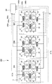
- FIG. 1 is a schematic configuration diagram of a manufacturing facility.
- the workpiece (workpiece) 11 is carried and sent to the conveying device 16.
- the transfer device 16 includes a robot arm 12 that holds the workpiece 11.
- the robot arm 12 is provided on the support base 13.
- the support table 13 is fixed to the transport table 14.
- the carriage 14 is disposed on a rail 15 and can move on the rail 15.
- one cell 30 for processing the workpiece 11 to manufacture the product 19 is disposed.
- a plurality of (four in the illustrated example) machine tools 31, 32, 33, and 34 for processing the workpiece 11 are arranged adjacent to each other in a straight line.
- these machine tools 31, 32, 33, and 34 for example, there are two or more rotating tool spindles having different directions, and a metal part cutting machine capable of machining each axis simultaneously. Is mentioned.
- a standby table 21 is provided on one side of the machine tool 31 to wait for the workpiece 11 carried into the cell 30.
- Workpieces processed by the machine tools 31, 32, 33 between the machine tool 31 and the machine tool 32, between the machine tool 32 and the machine tool 33, and between the machine tool 33 and the machine tool 34 Standby stands 22, 23, and 24 for waiting 11 are installed.
- On one side of the machine tool 34 a stand 25 for waiting for the product 19 is installed.
- Examples of the standby tables 21, 22, 23, 24, and 25 include tables that can wait for at least two workpieces 11 or products 19.
- the transfer device 16 and the machine tools 31, 32, 33, and 34 described above are connected to the control device 41 via signal lines 42a, 42b, 42c, 42d, and 42e. These signal lines 42a, 42b, 42c, 42d, and 42e can communicate signals bidirectionally. Therefore, the transfer device 16 and the machine tools 31, 32, 33, and 34 and the control device 41 can communicate bidirectionally.
- the above-described machine tools 31, 32, 33, and 34 have their own processes performed by the machine tools 31, 32, 33, and 34 themselves, and their own processes of the machine tools 31, 32, 33, and 34 themselves. It has a function that enables a pre-process to be performed before the process and a post-process to be performed after the self-process of the machine tools 31, 32, 33, and 34. That is, the first machine tool 31 has a function capable of performing the first process performed by the first machine tool 31 and the second process performed by the adjacent second machine tool 32. ing.
- the second machine tool 32 includes a second process performed by the second machine tool 32, a first process performed by the adjacent first machine tool 31, and an adjacent third machine tool 33. Has a function capable of performing the processing of the third step.
- the third machine tool 33 includes a third process performed by the third machine tool 33, a second process performed by the adjacent second machine tool 32, and an adjacent fourth machine tool 34.
- the fourth machine tool 34 has a function capable of performing the fourth process performed by the fourth machine tool 34 and the third process performed by the adjacent third machine tool 33. .
- the control device 41 described above has a function of controlling the transport device 16 and the machine tools 31, 32, 33, and 34. That is, the control device 41 performs machine tool 31, 32, 33, 34 so as to continuously process each process on the workpiece 11 according to the machining status of the workpiece 11 by the machine tools 31, 32, 33, 34. 34 and a function of controlling the transfer device 16. Specifically, the control device 41 has the following functions (I) to (IV).
- the control device 41 finishes the processing of its own process on the workpiece 11 by the machine tools 31, 32, 33, and there is no workpiece 11 on the stand 21, 21, 23 for the machine tool.
- the machine tool 31, 32, 33 has a function of controlling the machine tool 31, 32, 33 so as to perform the next process on the workpiece 11 that has been processed by the machine tool 31, 32, 33.
- the control device 41 is different from the above-mentioned workpiece in the machine tools 32, 33, 34 in the next process while the machine tool 31, 32, 33 is machining the next process on the workpiece 11.
- Machine tool 31, 32 so as to interrupt the machining of the next process for the workpiece, when the machining of its own process is finished and there is no workpiece on the stand 22, 22, 24 for the machine tool of the next process.
- 33 has a function of controlling the conveying device 16 so as to convey the workpiece, which has been processed in the next process, to the machine tools 32, 33, and 34 in the next process.
- the control device 41 monitors the process progress of the machine tools 31, 32, 33, and 34, and predicts the state in which each machine tool 31, 32, 33, and 34 has advanced its machining process from each time point. Then, the machining range for the workpiece 11 is instructed, and the machine tools 31, 32, 33, and 34 are conveyed so that the workpiece 11 is on the standby stands 21, 22, 23, and 24 for the machine tool at the end of the process. A function of controlling the device 16 is provided.
- a control device 41 for controlling the transfer device 16, and the machine tools 31, 32, 33, and 34 have a function of performing processing in the own process, processing in the previous process, and processing in the subsequent process on the workpiece.
- the machining of the workpiece 11 by the machine tools 31, 32, 33, 34 and the conveyance destination of the workpiece 11 are selected, and the machine tools 31, 32, 33, 34 are selected. Maximize uptime It can be. Therefore, even if the failure rates of the machine tools 31, 32, 33, and 34 are the same as the conventional case, the average operating rate is improved as compared with the conventional manufacturing equipment.
- one machine tool has a function of performing processing of the own process by the machine tool, processing of the pre-process and processing of the post-process on the workpiece 11, and processing of one process is performed on a plurality of machine tools.
- the product 19 can be efficiently produced while saving the space for the equipment. Furthermore, when the demand for the product 19 decreases, the machine tools 31, 32, 33, and 34 perform the processing of the own process by the machine tools 31, 32, 33, and the processing of the previous process and the process of the subsequent process. Since it has the function performed with respect to the workpiece 11, the fall of the operation rate of the machine tools 31, 32, 33, 34 can be suppressed. When the demand for the product 19 increases, it can be expanded in units of 30 cells.
- the machine tool By controlling the machine tools 31, 32, and 33 so as to perform the next process on the workpiece 11 that has been processed by the own process by 31, 32, and 33, there is no workpiece that performs the process of the own process. Therefore, it is possible to suppress a decrease in the operating rate of the machine tool. Therefore, the product 19 can be produced efficiently.
- control device 41 performs its own process for other workpieces different from the workpiece in the machine tools 32, 33, and 34 in the next process during machining of the next process for the workpiece 11 by the machine tools 31, 32, and 33.
- the machine tools 31, 32, 33 are controlled so as to interrupt the machining in the next process on the workpiece.
- the machine tool 31, 32, 33 performs the next process by controlling the conveying device 16 so as to convey the workpiece in which the next process is interrupted to the machine tool 32, 33, 34 in the next process.
- the control device 41 monitors the process progress of the machine tools 31, 32, 33, 34, predicts the state in which each machine tool 31, 32, 33, 34 has advanced its machining process from each time point, and the workpiece 11
- the machine tool 31, 32, 33, 34 and the conveying device 16 are controlled so that the workpiece 11 is on the stand 21, 21, 23, 24 for the machine tool at the end of the process.
- the operating rate of the machine tool 32, 33, 34 decreases due to the absence of a workpiece to be processed in its own process. Can be suppressed. Therefore, the production rate of the product 19 can be improved.
- control device 41 controls the transfer device 16 so as to pass the failed machine tool and transfer the workpiece 11 to the machine tool in the next process.
- the processing of the failed machine tool in its own process can be performed by another machine tool, and a reduction in the production rate of the product 19 can be suppressed.
- the conveyance of the workpiece 11 by the conveying device 16 becomes easy, the time required for conveying the workpiece 11 is shortened, and the production rate of the product 19 Can be suppressed.
- the machine tools 31, 32, 33, and 34 are arranged adjacent to each other in the order in which the workpiece 11 is processed, so that the workpiece 11 can be easily transferred by the transfer device 16 and is required for transferring the workpiece 11.
- the time can be shortened and the decrease in the production rate of the product 19 can be suppressed.
- FIG. 2 is a schematic configuration diagram of the manufacturing facility.
- the manufacturing facility according to the second embodiment of the present invention is a modification of the arrangement of the transfer device 16 and the machine tools 31, 32, 33, and 34 included in the manufacturing facility 50 according to the first embodiment of the present invention described above. Otherwise, it has the same configuration.
- the same reference numerals are given to the same apparatus as the manufacturing facility 50 according to the first embodiment of the present invention described above, and the description thereof is omitted.
- the manufacturing facility 100 includes a cell 80 in which four machine tools 31, 32, 33, and 34 are arranged around the transport device 16, as shown in FIG. Specifically, in this cell 80, a second machine tool 32 and a third machine tool 33 are arranged adjacent to the first machine tool 31. A fourth machine tool 34 is disposed adjacent to the second machine tool 32 and the third machine tool 33. A stand 21 is disposed adjacent to the first machine tool 31. A stand 22 is arranged adjacent to the second machine tool 32. A stand 23 is arranged between the first machine tool 31 and the third machine tool 33. A standby base 24 is disposed between the second machine tool 32 and the fourth machine tool 34. A stand 25 is arranged adjacent to the fourth machine tool 34.
- Reference numeral 67 a is a carry-in device for carrying the workpiece 11 into the standby table 21, and reference numeral 67 b is a carry-out device for carrying out the product 19.
- the control device 41 has the above-described functions (I) to (IV), and each process is continuously performed on the workpiece 11 in accordance with the machining status of the workpiece 11 by the machine tools 31, 32, 33, and 34.
- the machine tools 31, 32, 33, and 34 and the transfer device 16 are controlled so as to perform processing.
- the same effects as the manufacturing facility 50 according to the first embodiment described above can be obtained, and the machine tools 31, 32, 33, and 34 around the transport device 16 can be provided. Since the installation area of the machine tools 31, 32, 33, and 34 and the transfer device 16 can be minimized, further space saving of the facility can be achieved.
- the manufacturing equipment 100 which conveys the workpiece 11 with the one robot arm 12 which the conveying apparatus 16 comprises, it shall be set as the manufacturing equipment which comprises the conveying apparatus which conveys a workpiece with several robot arms. Is also possible. Even such a manufacturing facility has the same effects as the manufacturing facility 100 described above.
- FIG. 3 is a schematic configuration diagram of a manufacturing facility.
- the manufacturing facility according to the third embodiment of the present invention is obtained by changing the number of cells 30 included in the manufacturing facility 50 according to the first embodiment of the present invention described above, and has the same configuration.
- the same equipment as the manufacturing facility 50 according to the above-described first embodiment of the present invention is denoted by the same reference numeral, and the description thereof is omitted.
- the manufacturing facility 200 has three cells 30A, 30B, and 30C as shown in FIG.
- Each machine tool 31, 32, 33, 34 of each cell 30A, 30B, 30C is connected to the control device 241 via signal lines 242a, 242b, 242c.
- Reference numeral 216 denotes a transport device that transports the workpiece 11 and the product 19. The transport device 216 is connected to the control device 241 via a signal line (not shown).
- the control device 241 has the functions (I) to (IV) described above, and each process is continuously performed on the workpiece 11 in accordance with the machining status of the workpiece 11 by the machine tools 31, 32, 33, and 34.
- the machine tools 31, 32, 33, and 34 and the transfer device 216 are controlled so as to perform the above processing.
- a plurality of machine tools 31, 32, 33, 34 form one cell 30 in the process from processing the workpiece 11 to the product 19.
- the production amount of the product 19 can be increased or decreased depending on the demand of the product 19 for each cell. Can be adjusted easily.
- FIG. 4 is a schematic configuration diagram of the manufacturing facility.
- the manufacturing facility according to the fourth embodiment of the present invention is obtained by changing the number of cells 80 included in the manufacturing facility 100 according to the above-described second embodiment of the present invention, and has the same configuration.
- the same apparatus as that of the manufacturing facility 100 according to the second embodiment of the present invention described above is denoted by the same reference numeral, and the description thereof is omitted.
- the manufacturing facility 300 has three cells 80A, 80B, and 80C as shown in FIG.
- the transfer device 16 of each cell 80A, 80B, 80C is connected to the control device 341 via signal lines 342a, 343a, 344a.
- the machine tools 31, 32, 33, and 34 of the cells 80A, 80B, and 80C are connected to the control device 341 via signal lines 342b, 343b, and 344b.
- Reference numeral 317a is a carry-in device for carrying the workpiece 11 into the standby table 21 of each cell 30A, 30B, 30C.
- Reference numeral 317b denotes an unloading device for unloading the product 19 from the standby table 25 of each cell 30A, 30B, 30C.
- the carry-in device 317a and the carry-out device 317b are connected to the control device 341 via a signal line (not shown).
- the control device 341 has the functions (I) to (IV) described above, and each process is continuously performed on the workpiece 11 in accordance with the machining status of the workpiece 11 by the machine tools 31, 32, 33, and 34.
- the machine tools 31, 32, 33, and 34 and the transfer devices 16, 317a, and 317b are controlled so as to perform the above processing.
- a plurality of machine tools 31, 32, 33, 34 form one cell 80 in the process from processing the workpiece 11 to the product 19.
- the production amount of the product 19 can be increased or decreased depending on the demand of the product 19 for each cell. Can be adjusted easily.
- manufacturing equipment 50, 100 applied to equipment having a cell for manufacturing the product 19 by processing the workpiece 11 in four steps.
- a cell for manufacturing a product by processing three steps on a workpiece with three machine tools, and five or more steps on a workpiece with five or more machine tools It is also possible to apply to a manufacturing facility having a cell for manufacturing a product by performing the above process. Even such a manufacturing facility has the same effects as the manufacturing facilities 50, 100, 200, and 300 described above.
Landscapes
- Engineering & Computer Science (AREA)
- Mechanical Engineering (AREA)
- General Engineering & Computer Science (AREA)
- Manufacturing & Machinery (AREA)
- Quality & Reliability (AREA)
- Physics & Mathematics (AREA)
- General Physics & Mathematics (AREA)
- Automation & Control Theory (AREA)
- Multi-Process Working Machines And Systems (AREA)
- General Factory Administration (AREA)
Abstract
Description
本発明に係る製造設備を4工程の加工により製品を製造する設備に適用した場合の第一の実施形態につき図1を用いて説明する。
図1は、製造設備の概略構成図である。
制御装置41は、工作機械31,32,33にて工作物11に対する自工程の加工が終了し、かつ当該工作機械用の待機台21,22,23に工作物11が無い場合、当該工作機械31,32,33による自工程の加工が終了した工作物11に対して次工程の加工を行うように工作機械31,32,33を制御する機能を備えている。
制御装置41は、工作機械31,32,33にて工作物11に対する次工程の加工中に次工程の工作機械32,33,34にて前記工作物と異なる他の工作物に対する自工程の加工が終了し、かつ次工程の工作機械用の待機台22,23,24に工作物が無い場合、前記工作物に対する次工程の加工を中断するように工作機械31,32,33を制御し、次工程の加工を中断した工作物を前記次工程の工作機械32,33,34へ搬送するように搬送装置16を制御する機能を備えている。
制御装置41は、工作機械31,32,33,34の工程進捗度を監視し、各時点から各工作機械31,32,33,34がその加工工程を進めた状態を予測し、工作物11に対する加工範囲を指示してその工程終了時点で当該工作機械用の待機台21,22,23,24に工作物11があるように工作機械31,32,33,34および搬送装置16を制御する機能を備えている。
制御装置41は、工作機械31,32,33,34のうちの一つが故障した場合、故障した工作機械を通過して次工程の工作機械へ工作物11を搬送するように搬送装置16を制御する機能を備えている。
本発明に係る製造設備を4工程の加工により製品を製造する設備に適用した場合の第二の実施形態につき図2を用いて具体的に説明する。
図2は、製造設備の概略構成図である。
本発明の第二の実施形態に係る製造設備において、上述した本発明の第一の実施形態に係る製造設備50と同一装置には同一符号を付記しその説明を省略する。
本発明に係る製造設備を4工程の加工により製品を製造するセルを3つ具備する設備に適用した場合の第三の実施形態につき図3を用いて説明する。
図3は、製造設備の概略構成図である。
本発明の第三の実施形態に係る製造設備において、上述した本発明の第一の実施形態に係る製造設備50と同一装置には同一符号を付記しその説明を省略する。
本発明に係る製造設備を4工程の加工により製品を製造するセルを3つ具備する設備に適用した場合の第四の実施形態につき図4を用いて説明する。
図4は、製造設備の概略構成図である。
本発明の第四の実施形態に係る製造設備において、上述した本発明の第二の実施形態に係る製造設備100と同一装置には同一符号を付記しその説明を省略する。
上述した本発明に係る製造設備の第一~第四の実施形態では、工作物11に対して4つの工程の加工で製品19を製造するセルを具備する設備に適用した製造設備50,100,200,300を用いて説明したが、3台の工作機械により工作物に対して3工程の加工を行って製品を製造するセルや、5台以上の工作機械により工作物に対して5工程以上の加工を行って製品を製造するセルを具備する製造設備に適用することも可能である。このような製造設備であっても、上述した製造設備50,100,200,300と同様な作用効果を奏する。
Claims (9)
- 工作物を加工する複数の工作機械と、
前記工作物を搬送する搬送装置と、
前記工作機械および前記搬送装置を制御する制御装置とを具備し、
前記工作機械は、自工程の加工と前工程の加工および後工程の加工を前記工作物に対して行う機能を備え、
前記制御装置は、前記複数の工作機械による工作物の加工状況に応じて前記工作物に対し連続的に各工程の加工を行うように前記工作機械および前記搬送装置を制御した
ことを特徴とする製造設備。 - 請求項1に記載された製造設備であって、
前記工作機械毎に前記工作物を待機させる待機台をさらに具備し、
前記制御装置は、前記工作機械にて前記工作物に対する自工程の加工が終了し、かつ当該工作機械用の待機台に工作物が無い場合、当該工作機械による自工程の加工が終了した工作物に対して次工程の加工を行うように前記工作機械を制御する
ことを特徴とする製造設備。 - 請求項2に記載された製造設備であって、
前記制御装置は、前記工作機械にて前記工作物に対する次工程の加工中に次工程の工作機械にて前記工作物と異なる他の工作物に対する自工程の加工が終了し、かつ次工程の工作機械用の待機台に工作物が無い場合、前記工作物に対する次工程の加工を中断するように前記工作機械を制御し、次工程の加工を中断した工作物を前記次工程の工作機械へ搬送するように前記搬送装置を制御する
ことを特徴とする製造設備。 - 請求項3に記載された製造設備であって、
前記制御装置は、前記複数の工作機械の工程進捗度を監視し、各時点から各工作機械がその加工工程を進めた状態を予測し、前記工作物に対する加工範囲を指示してその工程終了時点で当該工作機械用の待機台に工作物があるように前記複数の工作機械および前記搬送装置を制御する
ことを特徴とする製造設備。 - 請求項1乃至請求項4の何れか一項に記載された製造設備であって、
前記制御装置は、前記工作機械が故障した場合、故障した工作機械を通過して次工程の工作機械へ工作物を搬送するように前記搬送装置を制御する
ことを特徴とする製造設備。 - 請求項1乃至請求項5の何れか一項に記載された製造設備であって、
前記複数の工作機械は、直線状に配置される
ことを特徴とする製造設備。 - 請求項6に記載された製造設備であって、
前記複数の工作機械は、前記工作物を加工する工程の順番で隣接して配置される
ことを特徴とする製造設備。 - 請求項1乃至請求項5の何れか一項に記載された製造設備であって、
前記複数の工作機械は、前記搬送装置の周りに配置される
ことを特徴とする製造設備。 - 請求項1乃至請求項8の何れか一項に記載された製造設備であって、
前記複数の工作機械は、前記工作物を加工して製品になるまでの工程で一つのセルをなし、
前記セルを複数具備する
ことを特徴とする製造設備。
Priority Applications (4)
| Application Number | Priority Date | Filing Date | Title |
|---|---|---|---|
| US12/864,305 US20110030185A1 (en) | 2008-01-25 | 2008-11-06 | Production facility |
| CN2008801251495A CN101918174A (zh) | 2008-01-25 | 2008-11-06 | 制造设备 |
| EP08871171A EP2239093A4 (en) | 2008-01-25 | 2008-11-06 | PRODUCTION INSTALLATION |
| KR1020107016608A KR101196503B1 (ko) | 2008-01-25 | 2008-11-06 | 제조 설비 |
Applications Claiming Priority (2)
| Application Number | Priority Date | Filing Date | Title |
|---|---|---|---|
| JP2008-014456 | 2008-01-25 | ||
| JP2008014456A JP2009172722A (ja) | 2008-01-25 | 2008-01-25 | 製造設備 |
Publications (1)
| Publication Number | Publication Date |
|---|---|
| WO2009093368A1 true WO2009093368A1 (ja) | 2009-07-30 |
Family
ID=40900884
Family Applications (1)
| Application Number | Title | Priority Date | Filing Date |
|---|---|---|---|
| PCT/JP2008/070224 Ceased WO2009093368A1 (ja) | 2008-01-25 | 2008-11-06 | 製造設備 |
Country Status (7)
| Country | Link |
|---|---|
| US (1) | US20110030185A1 (ja) |
| EP (1) | EP2239093A4 (ja) |
| JP (1) | JP2009172722A (ja) |
| KR (1) | KR101196503B1 (ja) |
| CN (1) | CN101918174A (ja) |
| TW (1) | TW200940249A (ja) |
| WO (1) | WO2009093368A1 (ja) |
Families Citing this family (10)
| Publication number | Priority date | Publication date | Assignee | Title |
|---|---|---|---|---|
| JP2010076006A (ja) | 2008-09-24 | 2010-04-08 | Mitsubishi Heavy Ind Ltd | 加工ラインモジュール及び加工設備 |
| JP5741616B2 (ja) * | 2013-03-18 | 2015-07-01 | 株式会社安川電機 | 生産システム及び製品の生産方法 |
| DE102013008065A1 (de) * | 2013-05-10 | 2014-11-13 | Volkswagen Aktiengesellschaft | Anlage zur Herstellung von Produkten |
| DE102014101874A1 (de) * | 2014-02-14 | 2015-08-20 | Mag Ias Gmbh | Fertigungssystem mit einer Mehrzahl von Werkzeugmaschinen und Verfahren zum Betreiben eines Fertigungssystems |
| DE102014101867A1 (de) * | 2014-02-14 | 2015-08-20 | Mag Ias Gmbh | Fertigungssystem mit einer Mehrzahl von Werkzeugmaschinen und Verfahren zum Betreiben eines Fertigungssystems |
| KR101952123B1 (ko) | 2017-02-27 | 2019-02-26 | (주)지컴 | 도킹 스테이션이 구비된 프레스 몰드 설비 |
| CN107042414B (zh) * | 2017-04-13 | 2023-11-10 | 北京理工大学 | 一种可重构的加工系统 |
| GB201721309D0 (en) | 2017-12-19 | 2018-01-31 | Renishaw Plc | Production and measurement of workpieces |
| CN117283358A (zh) * | 2023-11-16 | 2023-12-26 | 重庆红江机械有限责任公司 | 一种滚轮自动加工系统 |
| DE102024115854A1 (de) * | 2024-06-06 | 2025-12-11 | TRUMPF Laser- und Systemtechnik SE | Verfahren zum Betreiben einer Fertigungskette |
Citations (6)
| Publication number | Priority date | Publication date | Assignee | Title |
|---|---|---|---|---|
| JPS63106591U (ja) * | 1986-12-24 | 1988-07-09 | ||
| JPH0944226A (ja) * | 1995-07-28 | 1997-02-14 | Nissan Motor Co Ltd | ロボット制御装置 |
| JPH11188579A (ja) * | 1997-12-25 | 1999-07-13 | Toyota Motor Corp | マトリクス式生産設備 |
| JP3111843B2 (ja) | 1995-01-19 | 2000-11-27 | 豊田工機株式会社 | トランスファマシン |
| JP3173309B2 (ja) | 1995-02-22 | 2001-06-04 | 豊田工機株式会社 | トランスファマシン |
| JP2003285250A (ja) * | 2002-03-26 | 2003-10-07 | Toyota Motor Corp | 工作機械のワーク搬入出・搬送装置及び自動生産ライン |
Family Cites Families (5)
| Publication number | Priority date | Publication date | Assignee | Title |
|---|---|---|---|---|
| US3576540A (en) * | 1967-11-20 | 1971-04-27 | Sundstrand Corp | Plural machine tool and part handling control system |
| JPS59209745A (ja) * | 1983-05-13 | 1984-11-28 | Toyoda Mach Works Ltd | パレツト搬入搬出装置 |
| US5237508A (en) * | 1989-08-10 | 1993-08-17 | Fujitsu Limited | Production control system |
| US6104965A (en) * | 1997-05-01 | 2000-08-15 | Motorola, Inc. | Control of workstations in assembly lines |
| CN1252552C (zh) * | 2000-04-01 | 2006-04-19 | Abb研究有限公司 | 用于综合生产线自适应控制的方法和系统 |
-
2008
- 2008-01-25 JP JP2008014456A patent/JP2009172722A/ja active Pending
- 2008-11-06 WO PCT/JP2008/070224 patent/WO2009093368A1/ja not_active Ceased
- 2008-11-06 US US12/864,305 patent/US20110030185A1/en not_active Abandoned
- 2008-11-06 EP EP08871171A patent/EP2239093A4/en not_active Withdrawn
- 2008-11-06 KR KR1020107016608A patent/KR101196503B1/ko not_active Expired - Fee Related
- 2008-11-06 CN CN2008801251495A patent/CN101918174A/zh active Pending
- 2008-11-19 TW TW097144732A patent/TW200940249A/zh not_active IP Right Cessation
Patent Citations (6)
| Publication number | Priority date | Publication date | Assignee | Title |
|---|---|---|---|---|
| JPS63106591U (ja) * | 1986-12-24 | 1988-07-09 | ||
| JP3111843B2 (ja) | 1995-01-19 | 2000-11-27 | 豊田工機株式会社 | トランスファマシン |
| JP3173309B2 (ja) | 1995-02-22 | 2001-06-04 | 豊田工機株式会社 | トランスファマシン |
| JPH0944226A (ja) * | 1995-07-28 | 1997-02-14 | Nissan Motor Co Ltd | ロボット制御装置 |
| JPH11188579A (ja) * | 1997-12-25 | 1999-07-13 | Toyota Motor Corp | マトリクス式生産設備 |
| JP2003285250A (ja) * | 2002-03-26 | 2003-10-07 | Toyota Motor Corp | 工作機械のワーク搬入出・搬送装置及び自動生産ライン |
Non-Patent Citations (1)
| Title |
|---|
| See also references of EP2239093A4 |
Also Published As
| Publication number | Publication date |
|---|---|
| TWI369269B (ja) | 2012-08-01 |
| EP2239093A4 (en) | 2012-01-25 |
| CN101918174A (zh) | 2010-12-15 |
| TW200940249A (en) | 2009-10-01 |
| JP2009172722A (ja) | 2009-08-06 |
| US20110030185A1 (en) | 2011-02-10 |
| KR101196503B1 (ko) | 2012-11-01 |
| KR20100102184A (ko) | 2010-09-20 |
| EP2239093A1 (en) | 2010-10-13 |
Similar Documents
| Publication | Publication Date | Title |
|---|---|---|
| WO2009093368A1 (ja) | 製造設備 | |
| JP6427866B2 (ja) | フレキシブル生産システム | |
| EP2246136A1 (en) | Machine and method for machining crankshaft ends | |
| US4251957A (en) | Workpiece transfer apparatus for a plurality of machine tools | |
| JP6286934B2 (ja) | フレキシブル生産システム | |
| CN105855997B (zh) | 柔性生产线控制系统及方法 | |
| CN113423533B (zh) | 托盘搬送系统、托盘搬送方法以及托盘搬送程序 | |
| CN208758627U (zh) | 一种机械手及自动化生产线 | |
| US9334125B2 (en) | Conveyance system for machining apparatus | |
| WO2016047227A1 (ja) | 搬送方法、搬送制御装置、搬送制御プログラム及びコンピュータ読み取り可能な記録媒体 | |
| CN203679289U (zh) | 椼架式自动送脱料机构 | |
| JP3023438B2 (ja) | トランスファー加工装置 | |
| JPS62264852A (ja) | ロボツトを含む加工システムにおける制御方法 | |
| JP2005001073A (ja) | 工作機械システムおよびそのワーク搬送方法 | |
| JP4794014B2 (ja) | 生産システム | |
| CN211218699U (zh) | 一种轮毂类设备加工生产系统 | |
| JP2006026818A (ja) | 工作機械 | |
| JPS59214910A (ja) | フレキシブル複合加工セルの運転制御方式 | |
| CN111752234A (zh) | 一种柔性环形生产线 | |
| JP3058982B2 (ja) | 製造ラインにおけるトラッキング制御方法 | |
| WO2020235171A1 (ja) | 搬送システム | |
| BG3993U1 (bg) | Технологична линия за производство на детайли от кръгла тел | |
| JP2010191749A (ja) | 混流生産ライン | |
| JPH08108351A (ja) | 混流生産システム | |
| JP2011083871A (ja) | 生産システム |
Legal Events
| Date | Code | Title | Description |
|---|---|---|---|
| WWE | Wipo information: entry into national phase |
Ref document number: 200880125149.5 Country of ref document: CN |
|
| 121 | Ep: the epo has been informed by wipo that ep was designated in this application |
Ref document number: 08871171 Country of ref document: EP Kind code of ref document: A1 |
|
| WWE | Wipo information: entry into national phase |
Ref document number: 2008871171 Country of ref document: EP |
|
| ENP | Entry into the national phase |
Ref document number: 20107016608 Country of ref document: KR Kind code of ref document: A |
|
| WWE | Wipo information: entry into national phase |
Ref document number: 1586/MUMNP/2010 Country of ref document: IN |
|
| NENP | Non-entry into the national phase |
Ref country code: DE |
|
| WWE | Wipo information: entry into national phase |
Ref document number: PI 2010003497 Country of ref document: MY |
|
| WWE | Wipo information: entry into national phase |
Ref document number: 12864305 Country of ref document: US |