WO2009093591A1 - アンテナ及び無線通信装置 - Google Patents
アンテナ及び無線通信装置 Download PDFInfo
- Publication number
- WO2009093591A1 WO2009093591A1 PCT/JP2009/050816 JP2009050816W WO2009093591A1 WO 2009093591 A1 WO2009093591 A1 WO 2009093591A1 JP 2009050816 W JP2009050816 W JP 2009050816W WO 2009093591 A1 WO2009093591 A1 WO 2009093591A1
- Authority
- WO
- WIPO (PCT)
- Prior art keywords
- antenna
- conductor
- radiation
- resonance frequency
- ghz
- Prior art date
- Legal status (The legal status is an assumption and is not a legal conclusion. Google has not performed a legal analysis and makes no representation as to the accuracy of the status listed.)
- Ceased
Links
Images









Classifications
-
- H—ELECTRICITY
- H01—ELECTRIC ELEMENTS
- H01Q—ANTENNAS, i.e. RADIO AERIALS
- H01Q9/00—Electrically-short antennas having dimensions not more than twice the operating wavelength and consisting of conductive active radiating elements
- H01Q9/04—Resonant antennas
- H01Q9/30—Resonant antennas with feed to end of elongated active element, e.g. unipole
- H01Q9/42—Resonant antennas with feed to end of elongated active element, e.g. unipole with folded element, the folded parts being spaced apart a small fraction of the operating wavelength
-
- H—ELECTRICITY
- H01—ELECTRIC ELEMENTS
- H01Q—ANTENNAS, i.e. RADIO AERIALS
- H01Q1/00—Details of, or arrangements associated with, antennas
- H01Q1/12—Supports; Mounting means
- H01Q1/22—Supports; Mounting means by structural association with other equipment or articles
- H01Q1/24—Supports; Mounting means by structural association with other equipment or articles with receiving set
- H01Q1/241—Supports; Mounting means by structural association with other equipment or articles with receiving set used in mobile communications, e.g. GSM
- H01Q1/242—Supports; Mounting means by structural association with other equipment or articles with receiving set used in mobile communications, e.g. GSM specially adapted for hand-held use
- H01Q1/243—Supports; Mounting means by structural association with other equipment or articles with receiving set used in mobile communications, e.g. GSM specially adapted for hand-held use with built-in antennas
-
- H—ELECTRICITY
- H01—ELECTRIC ELEMENTS
- H01Q—ANTENNAS, i.e. RADIO AERIALS
- H01Q1/00—Details of, or arrangements associated with, antennas
- H01Q1/36—Structural form of radiating elements, e.g. cone, spiral, umbrella; Particular materials used therewith
-
- H—ELECTRICITY
- H01—ELECTRIC ELEMENTS
- H01Q—ANTENNAS, i.e. RADIO AERIALS
- H01Q5/00—Arrangements for simultaneous operation of antennas on two or more different wavebands, e.g. dual-band or multi-band arrangements
- H01Q5/30—Arrangements for providing operation on different wavebands
- H01Q5/307—Individual or coupled radiating elements, each element being fed in an unspecified way
- H01Q5/342—Individual or coupled radiating elements, each element being fed in an unspecified way for different propagation modes
- H01Q5/357—Individual or coupled radiating elements, each element being fed in an unspecified way for different propagation modes using a single feed point
Definitions
- the present invention relates to an antenna used in a wireless communication device such as a mobile phone that transmits and receives wireless signals.
- the present invention relates to an antenna that operates in a multiband frequency band such as a GSM band from 880 MHz to 960 MHz, a DCS band from 1710 MHz to 1880 MHz, a PCS band from 1850 MHz to 1990 MHz, and a UMTS band from 1920 MHz to 2170 MHz.
- An antenna provided with a meander slot on a meander patch see, for example, Non-Patent Document 1
- a monopole slot antenna see, for example, Non-Patent Document 2
- an antenna using a plurality of monopoles for example, Non-Patent Document 3
- PIFA Planar Inverted F Antenna
- a fractal antenna for example, see Non-Patent Document 7
- the multiband antenna used in the wireless communication apparatus must support GSM (880 MHz to 960 MHz or less), DCS (1710 MHz to 1880 MHz), PCS (1850 MHz to 1990 MHz or less), and UMTS (1920 MHz to 2170 MHz or less).
- the second resonance frequency band requires a wide band of 1710 MHz or more and 2170 MHz or less when DCS, PCS, and UMTS are combined.
- the antenna mounted on the mobile device is required to be small.
- multiband antennas are required to have input characteristics that can be matched in each band and to maintain omnidirectionality in each band as much as possible.
- An antenna having a meander slot on a meander patch requires a three-dimensional installation space.
- the radiation pattern changes greatly with changes in frequency, and omnidirectionality cannot be maintained.
- Non-Patent Document 2 In a monopole slot antenna (for example, see Non-Patent Document 2), since it is necessary to provide a slot on the ground substrate, the substrate must be processed. Further, the radiation pattern depends on the frequency, and omnidirectionality cannot be maintained.
- Non-Patent Documents 3, 4 and 5 Similar to the monopole slot antenna, the radiation pattern depends on the frequency, and omnidirectionality cannot be maintained.
- a PIFA for example, see Non-Patent Document 6
- a fractal antenna for example, see Non-Patent Document 7
- an object of the present invention is to provide an antenna that is small in size, has input characteristics that can be matched in each band, and that can maintain omnidirectionality, and a wireless communication apparatus equipped with the antenna.
- the inventor folds the arm-shaped radiation conductor to form the lower arm or the upper arm, and when the radiation conductor has a meander shape, the first resonance frequency band including the low-order resonance frequency does not change, and the higher-order resonance
- the present inventors have found a phenomenon in which the second resonance frequency band including the frequency shifts to a low frequency side or the band widens. Furthermore, the inventor has also found that omnidirectionality is maintained.
- the meander shape means a protrusion shape that protrudes at right angles to the lower arm, the upper arm, or the short-circuit pin that extends on a straight line that is equidistant from the ground conductor.
- the meander shape here includes a U-shape, a V-shape, and a shape in which the tip is L-shaped and cut off.
- the antenna according to the present invention has a ground conductor, a short-circuit pin made of a conductor, one end of which is connected to the ground conductor via the short-circuit pin, the other end is open, and one of the ends
- An radiating conductor fed from a feeding point wherein the radiating conductor is folded between one of the end portions and the other of the end portions, and is folded with a lower arm close to the ground conductor and
- An upper arm is configured, and at least a part of the lower arm or the upper arm has a meander shape.
- the antenna can be downsized by configuring the folded upper and lower arms. Further, since at least a part of the upper arm or the lower arm has a meander shape, the higher-order resonance frequency can be shifted to the lower frequency side. Thereby, the antenna according to the present invention is small and can match the input characteristics in each band. Furthermore, omnidirectionality is also maintained.
- the short-circuit pin has a meander shape.
- the second resonance frequency band can be widened.
- the radiating conductor and the short-circuit pin are made of one continuous conductor line.
- the antenna of the present invention can be easily manufactured.
- the radiation conductor is disposed on the same plane as the ground conductor.
- the ground conductor and the radiation conductor can be formed on the same substrate.
- the radiation conductor is arranged on a different plane from the ground conductor.
- the antenna can be miniaturized because it can be formed on a substrate different from the ground conductor without changing the characteristic of the resonance frequency.
- the radiation conductor or the short-circuit pin is bent at least one with a straight line parallel to a direction in which the lower arm or the upper arm extends as a fold. According to the present invention, the antenna can be miniaturized and mounted without changing the resonance frequency characteristics.
- the bent radiation conductor is fixed to a dielectric. According to the present invention, the antenna can be easily mounted and the entire length of the radiation conductor can be shortened.
- the radiation conductor is preferably a metal wire or a metal film formed on a flexible substrate. If it is a metal wire, it can be manufactured easily. If it is a metal film, it can be easily manufactured using a printing technique.
- a wireless communication apparatus includes the antenna according to the present invention.
- a wireless communication device that supports multiband with a small antenna can be provided.
- an antenna and a wireless communication apparatus that are small in size, have input characteristics that can be matched in each band, and can maintain omnidirectionality.
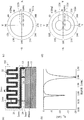
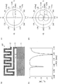
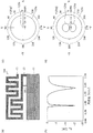
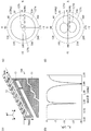
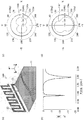
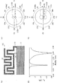
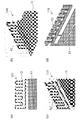
- Embodiment 1 An example of the antenna which concerns on Embodiment 1 is shown. It is an example of the antenna which concerns on Embodiment 2, (a) shows an antenna structure, (b) shows the input characteristic of an antenna, (c) and (d) shows the radiation characteristic in xy plane. It is a polar coordinate in this embodiment. It is an example of the antenna which concerns on Embodiment 3, (a) shows an antenna structure, (b) shows the input characteristic of an antenna, (c) and (d) shows the radiation characteristic in xy plane. It is an example of the antenna which concerns on Embodiment 4, (a) shows an antenna structure, (b) shows the input characteristic of an antenna, (c) and (d) shows the radiation characteristic in xy plane.
- Embodiment 5 It is an example of the antenna which concerns on Embodiment 5, (a) shows an antenna structure, (b) shows the input characteristic of an antenna, (c) and (d) shows the radiation characteristic in xy plane. It is an example of the antenna which concerns on Embodiment 6, (a) shows an antenna structure, (b) shows the input characteristic of an antenna, (c) and (d) shows the radiation characteristic in xy plane. It is an example of the antenna which concerns on Embodiment 7, (a) shows an antenna structure, (b) shows the input characteristic of an antenna, (c) and (d) shows the radiation characteristic in xy plane.
- the antenna which concerns on Embodiment 8 (a) shows an antenna structure, (b) shows the input characteristic of an antenna, (c) and (d) shows the radiation characteristic in xy plane. It is an example of the antenna which concerns on Embodiment 9, (a) shows an antenna structure, (b) shows the input characteristic of an antenna, (c) and (d) shows the radiation characteristic in xy plane. It is an example of the antenna which concerns on Embodiment 10, (a) shows an antenna structure, (b) shows the input characteristic of an antenna, (c) and (d) shows the radiation characteristic in xy plane.
- the antenna which concerns on Embodiment 11 shows an antenna structure, (b) shows the input characteristic of an antenna, (c) and (d) shows the radiation characteristic in xy plane.
- the antenna which concerns on Embodiment 12 shows an antenna structure, (b) shows the input characteristic of an antenna, (c) and (d) shows the radiation characteristic in xy plane.
- an antenna (a) is when the width of the radiation conductor is thin, (b) when the radiation conductor is perpendicular to the ground conductor, (c) is arranged on a plane different from the ground conductor.
- (D) shows the case where the bending width of the radiation conductor shown in Embodiment 7 is narrow.
- FIG. 1 shows an example of an antenna according to the present embodiment.
- the antenna 101 according to this embodiment includes a ground conductor 11, a radiation conductor 12, and a short-circuit pin 13.
- a short-circuit pin 13 is installed between the ground conductor 11 and the radiation conductor 12.
- the shorting pin 13 is from the edge of the ground conductor 11 to the feeding point 23.
- the radiation conductor 12 has one end 21 connected to the short-circuit pin 13 and the other end 22 open.
- the radiation conductor 12 is roughly divided into a lower arm 24 and an upper arm 25 bent at the tip.
- a meander structure is used to reduce the size of the antenna 101.
- the antenna 101 is fed with power to the ground conductor 11 and the radiating conductor 12 via the feeder 14.
- One end 21 of the radiation conductor 12 is connected to the feed line 14 and fed from a feed point 23.
- the total length of the radiation conductor 12 contributes to the operation in the first resonance frequency band including the low-order resonance frequency.
- the overall length of the radiating conductor 12 has a ⁇ 1/4.
- ⁇ 1 is the wavelength of the free space of the electromagnetic wave at the center frequency of the first resonance frequency band.
- the wavelength is shortened, in which case, the wavelength lambda 1 is a shortened wavelength.
- the first resonance frequency band can be adjusted by adjusting the length of the radiation conductor 12.
- the radiating conductor 12 is folded between one end 21 and the other end 22 to form a lower arm 24 and an upper arm 25. Since the radiation conductor 12 is folded, the antenna can be downsized.
- the lower arm 24 is a portion of the radiating conductor 12 that is close to the ground conductor 11.
- the upper arm 25 is a folded portion of the radiation conductor 12. If the upper arm 25 has not been bent in a previous lower arm 24, the high-order resonance frequency f 2 is about 3 times the low-order resonance frequency f 1. Therefore, if the low-order resonance frequency f 1 is 0.9 GHz, the high-order resonance frequency f 2 is 2.7 GHz, and the object cannot be achieved.
- the higher-order resonance frequency is significantly shifted to the lower frequency side than when the upper arm 25 is not bent.
- the second resonance frequency band can be adjusted to a frequency band suitable for multiband use, so that the antenna 101 can be used in multiband.
- the lower arm 24 extends in a straight line at an equal distance from the ground conductor 11 while being bent in a meander shape. For example, as shown in FIG. 1, if the portion of the ground conductor 11 that is close to the radiation conductor 12 is the edge of the ground conductor 11, the lower arm 24 is on a straight line parallel to the edge of the ground conductor 11. It is growing. Further, as shown in FIG. 14B, if the portion of the ground conductor 11 that is close to the radiation conductor 12 is the plane of the ground conductor 11, the lower arm 24 is parallel to the plane of the ground conductor 11. It extends on a straight line included in the plane. The upper arm 25 extends in parallel and opposite to the lower arm 24 while bending in a meander shape.
- the folded portion of the lower arm 24 and the upper arm 25 is not limited to a bent shape, but has a curved shape such as a semicircular shape or a semi-doughnut shape. There may be.
- the resonance frequency of the antenna can be changed by adjusting the position and number of the meander shapes 26 provided.
- the second resonance frequency band including the higher order resonance frequency can be adjusted.
- the resonance frequency can be adjusted to the frequency band used by the mobile phone.
- the antenna 101 can make the second resonance frequency band correspond to GSM, DCS, PCS, and UMTS.
- the higher order resonance frequency is shifted to the lower frequency side.
- the high-order resonance frequency can be shifted to the low-frequency side with almost no change in the low-order resonance frequency.
- the higher order resonance frequency can be further shifted to the lower frequency side.
- the higher-order resonance frequency can be shifted to the lower frequency side by providing the lower arm 24 than the upper arm 25.
- the antenna 101 not only can be adjusted so as to be matched in a desired frequency band, but the radiation characteristic becomes almost omnidirectional, as will be apparent from embodiments and examples described later. That is, by changing the position of the portion having the meander shape 26 in the upper arm 25 and the lower arm 24, the position of the current distribution contributing to radiation is changed, so that the directivity of the radiation characteristic can be adjusted. Because it can.
- the short-circuit pin 13 shorts between the ground conductor 11 and the radiation conductor 12.
- the short-circuit pin 13 has a meander shape 26.
- a meander shape 26 is provided in a portion of the short-circuit pin 13 that is parallel to the edge of the ground conductor 11.
- the radiation conductor 12 and the short-circuit pin 13 are composed of one continuous conductor line.
- the radiation conductor 12 is a metal wire or a metal film.
- the antenna 101 is composed of a single metal wire without branching, excluding the feed line 14. This structure can be made of a very thin metal film or a metal wire. In that case, it can be made very inexpensively.
- the radiation conductor 12 is a metal film, it is preferable that the radiation conductor 12 is formed on the flexible substrate. Since the radiation conductor 12 is formed on the flexible substrate, it is easy to bend the radiation conductor 12 while maintaining the meander shape 26.
- the antenna 101 has little influence on the characteristics even if it is installed at a relatively free relative position with respect to the ground conductor 11. This gives a degree of freedom to the installation location of the antenna 101 and facilitates antenna design.
- the radiation conductor 12 may be arranged on the same plane as the ground conductor 11. Since the radiation conductor 12 is disposed on the same plane as the ground conductor 11, the ground conductor 11 and the radiation conductor 12 can be formed on the same substrate. Further, the radiation conductor 12 may be arranged on a different plane from the ground conductor 11. The antenna 101 can be reduced in size without changing the characteristic of the resonance frequency.
- the radiation conductor 12 be bent one or more times with a straight line parallel to the extending direction of the lower arm 24 or the upper arm 25, that is, a straight line equidistant from the nearest portion of the ground conductor 11 as a fold.
- a straight line equidistant from the nearest portion of the ground conductor 11 as a fold As will be described later in Embodiment 7, Embodiment 8, and Embodiment 9, even if the radiation conductor 12 is bent with a straight line that is equidistant from the nearest portion of the ground conductor 11 as a fold, the resonance frequency characteristics do not change. For this reason, the antenna 101 can be reduced in size without changing the characteristic of the resonance frequency.
- the bent radiation conductor 12 is preferably fixed to a dielectric. Since the radiation conductor 12 is fixed, the meander shape 26 can be maintained.
- the fixing destination of the radiation conductor 12 is, for example, the edge of the substrate.
- the circuit in the wireless communication apparatus may be a laminated structure, the surface thereof may be shielded, and the radiation conductor 12 may be fixed around the circuit.
- the meander shape 26 can be maintained even when an impact is applied to the wireless communication device. Further, since the dielectric is provided in the vicinity of the radiation conductor 12, the low-order resonance frequency can be lowered. Thereby, it is possible to adjust the first resonance frequency band of the antenna.
- FIG. 2 is an example of an antenna according to the present embodiment, where (a) shows the antenna structure, (b) shows the input characteristics of the antenna, and (c) and (d) show the radiation characteristics on the xy plane.
- the upper arm has five meander shapes.
- the dimension of the ground conductor 11 is 70 ⁇ 40 mm 2 .
- the distance between the radiation conductor 12 and the ground conductor 11 is 3 mm.
- the short-circuit pin 13 is connected to the edge of the ground conductor 11.
- the feeder 14 is connected 8 mm inside from the edge of the ground conductor 11 to which the short-circuit pin 13 is connected.
- the radiation conductor 12 has a planar structure, and the overall dimension is 40 ⁇ 15 mm 2 .
- the radiation conductor 12 consists of a single line.
- the width of the radiation conductor 12 is 2 mm. All the distances between the radiation conductors 12 are 2 mm.
- the thickness of the radiation conductor 12 is not less than the skin depth at 0.9 GHz.
- the radiation conductor 12 when the radiation conductor 12 is a metal film, the radiation conductor 12 is a copper foil having a thickness of 10 ⁇ m or more.
- the example in which the radiation conductor 12 is integrated with the short-circuit pin 13 is shown. The same applies to the following embodiments.
- the characteristic impedance on the system side at the feeding point 23 of the antenna 102 is 50 ⁇ .
- Resonance frequency is the scattering parameter S 11 becomes small, it was about 0.85GHz and about 2.00 GHz.
- the radiation characteristic on the xy plane shown in FIG. 2C is a simulation result at a low-order resonance frequency of 0.85 GHz.
- the radiation characteristic on the xy plane shown in FIG. 2D is a simulation result at a high-order resonance frequency of 2.00 GHz.
- the notation uses the polar coordinates shown in FIG.
- the directivity in the whole and ⁇ direction is the radiation pattern 122a
- the directivity in the ⁇ direction is the radiation pattern 122b.
- the directivity in the whole and ⁇ direction is the radiation pattern 122c
- the directivity in the ⁇ direction is the radiation pattern 122d.
- it has good omnidirectionality at any resonance frequency.
- FIG. 4 shows an example of an antenna according to the present embodiment, where (a) shows the antenna structure, (b) shows the input characteristics of the antenna, and (c) and (d) show the radiation characteristics on the xy plane.
- the antenna 103 has a meander shape with four upper arms and one lower arm. Other structures such as the size of the ground conductor 11, the distance between the radiation conductor 12 and the ground conductor 11, the position of the short-circuit pin 13 and the feeder line 14, the width of the radiation conductor 12, and the distance between the radiation conductors 12 Same as 2.
- the radiation characteristic on the xy plane shown in FIG. 4C is a simulation result at a low-order resonance frequency of 0.85 GHz.
- the radiation characteristic on the xy plane shown in FIG. 4D is a simulation result at a high-order resonance frequency of 1.95 GHz.
- the notation uses the polar coordinates shown in FIG.
- the directivity in the whole and ⁇ directions is as a radiation pattern 124a
- the directivity in the ⁇ direction is as a radiation pattern 124b.
- the directivity in the whole and the ⁇ direction is a radiation pattern 124c
- the directivity in the ⁇ direction is a radiation pattern 124d.
- FIG. 4C and FIG. 4D it can be seen that the antenna has good omnidirectionality at any resonance frequency.
- FIG. 5 shows an example of an antenna according to the present embodiment, where (a) shows the antenna structure, (b) shows the input characteristics of the antenna, and (c) and (d) show the radiation characteristics on the xy plane.
- the antenna 104 has a meander shape with three upper arms and two lower arms. Other structures such as the size of the ground conductor 11, the distance between the radiation conductor 12 and the ground conductor 11, the position of the short-circuit pin 13 and the feeder line 14, the width of the radiation conductor 12, and the distance between the radiation conductors 12 are described in the embodiment. Same as 2.
- the radiation characteristic on the xy plane shown in FIG. 5C is a simulation result at a low-order resonance frequency of 0.85 GHz.
- the radiation characteristic on the xy plane shown in FIG. 5D is a simulation result at a high-order resonance frequency of 1.80 GHz.
- the notation uses the polar coordinates shown in FIG.
- the directivity in the whole and ⁇ direction is the radiation pattern 125a
- the directivity in the ⁇ direction is the radiation pattern 125b.
- the directivity in the entire direction and the ⁇ direction is the radiation pattern 125c
- the directivity in the ⁇ direction is the radiation pattern 125d.
- FIGS. 5 (c) and 5 (d) it can be seen that there is good omnidirectionality at any resonance frequency.
- FIG. 6 shows an example of the antenna according to the present embodiment, where (a) shows the antenna structure, (b) shows the input characteristics of the antenna, and (c) and (d) show the radiation characteristics on the xy plane.
- the antenna 105 has a meander shape with two upper arms and three lower arms. Other structures such as the size of the ground conductor 11, the distance between the radiation conductor 12 and the ground conductor 11, the position of the short-circuit pin 13 and the feeder line 14, the width of the radiation conductor 12, and the distance between the radiation conductors 12 are described in the embodiment. Same as 2.
- the radiation characteristic on the xy plane shown in FIG. 6C is a simulation result at a low-order resonance frequency of 0.85 GHz.
- the radiation characteristic on the xy plane shown in FIG. 6D is a simulation result at a high-order resonance frequency of 1.70 GHz.
- the notation uses the polar coordinates shown in FIG.
- the directivity in the whole and the ⁇ direction is the radiation pattern 126a
- the directivity in the ⁇ direction is the radiation pattern 126b.
- the directivity in the whole and the ⁇ direction is the radiation pattern 126c
- the directivity in the ⁇ direction is the radiation pattern 126d.
- FIG. 6C and FIG. 6D it can be seen that the antenna has good omnidirectionality at any resonance frequency.
- FIG. 7 shows an example of an antenna according to the present embodiment, where (a) shows the antenna structure, (b) shows the input characteristics of the antenna, and (c) and (d) show the radiation characteristics on the xy plane.
- the antenna 106 in the antenna 102 shown in FIG. 2, the upper arm is bent once by a straight line parallel to the extending direction of the upper arm.
- the bent upper arm is the xy plane.
- the crease is 8 mm from the bottom of the lower arm.
- the volume of the space occupied by the radiation conductor 12 is 40 ⁇ 8 ⁇ 7 mm 3 .
- the lower arm or the short-circuit pin may be bent. The same applies to the following embodiments.
- the radiation characteristic on the xy plane shown in FIG. 7C is a simulation result at a low-order resonance frequency of 0.90 GHz.
- the radiation characteristic on the xy plane shown in FIG. 7D is a simulation result at a high-order resonance frequency of 2.00 GHz.
- the notation uses the polar coordinates shown in FIG.
- the directivity in the whole and ⁇ direction is as a radiation pattern 127a
- the directivity in the ⁇ direction is as a radiation pattern 127b.
- the directivity in the whole and ⁇ direction is a radiation pattern 127c
- the directivity in the ⁇ direction is a radiation pattern 127d.
- the antenna has good omnidirectionality at any resonance frequency.
- the bent radiation conductor 12 may be wound around a dielectric. By doing so, not only the antenna shape can be maintained, but also the size of the antenna can be reduced by the dielectric.
- FIG. 8 shows an example of the antenna according to the present embodiment, where (a) shows the antenna structure, (b) shows the input characteristics of the antenna, and (c) and (d) show the radiation characteristics on the xy plane.
- the upper arm of the antenna 102 shown in FIG. 2 is bent twice with a straight line parallel to the extending direction of the upper arm as a fold.
- the crease is 5 mm from the bottom of the lower arm and further 5 mm from the crease.
- the volume of the space occupied by the radiation conductor 12 is 40 ⁇ 5 ⁇ 5 mm 3 .
- the radiation characteristic on the xy plane shown in FIG. 8C is a simulation result at a low-order resonance frequency of 0.90 GHz.
- the radiation characteristic on the xy plane shown in FIG. 8D is a simulation result at a high-order resonance frequency of 2.00 GHz.
- the notation uses the polar coordinates shown in FIG.
- the directivity in the whole and the ⁇ direction is the radiation pattern 128a
- the directivity in the ⁇ direction is the radiation pattern 128b.
- the directivity in the whole and ⁇ direction is a radiation pattern 128c
- the directivity in the ⁇ direction is a radiation pattern 128d.
- the antenna has good omnidirectionality at any resonance frequency.
- the bent radiation conductor 12 may be wound around a dielectric. By doing so, not only the meander shape of the radiation conductor 12 can be maintained, but also the size of the antenna can be reduced by the dielectric.
- FIG. 9 shows an example of the antenna according to the present embodiment, where (a) shows the antenna structure, (b) shows the input characteristics of the antenna, and (c) and (d) show the radiation characteristics on the xy plane.
- the antenna 108 in the antenna 102 shown in FIG. 2, the upper arm is bent three times with a straight line parallel to the extending direction of the upper arm as a fold.
- the crease is a position 4 mm away from the bottom of the lower arm and 4 mm away from the crease.
- the volume of the space occupied by the radiation conductor 12 is 40 ⁇ 4 ⁇ 4 mm 3 .
- the radiation characteristic on the xy plane shown in FIG. 9C is a simulation result at a low-order resonance frequency of 0.90 GHz.
- the radiation characteristic on the xy plane shown in FIG. 9D is a simulation result at a high-order resonance frequency of 2.00 GHz.
- the notation uses the polar coordinates shown in FIG.
- the directivity in the whole and ⁇ direction is as a radiation pattern 129a
- the directivity in the ⁇ direction is as a radiation pattern 129b.
- the directivity in the whole and ⁇ direction is a radiation pattern 129c
- the directivity in the ⁇ direction is a radiation pattern 129d.
- the radiation characteristic on the xy plane shown in FIG. 9D is a simulation result at a high-order resonance frequency of 2.00 GHz.
- the notation uses the polar coordinates shown
- the antenna has a good omnidirectionality in any frequency band.
- the bent radiation conductor 12 may be wound around a dielectric. By doing so, not only the antenna shape can be maintained, but also the size of the antenna can be reduced by the dielectric.
- FIG. 10 shows an example of an antenna according to the present embodiment, where (a) shows the antenna structure, (b) shows the input characteristics of the antenna, and (c) and (d) show the radiation characteristics on the xy plane.
- the radiating conductor 12 is arranged perpendicular to the ground conductor 11 in the antenna 102 shown in FIG. 2. For example, when the coordinate axis is aligned with the radiation conductor 12 and the radiation conductor 12 is disposed on the xz plane, the ground conductor 11 is disposed on the xy plane.
- the radiation characteristic on the xy plane shown in FIG. 10C is a simulation result at a low-order resonance frequency of 0.85 GHz.
- the radiation characteristic on the xy plane shown in FIG. 10D is a simulation result at a high-order resonance frequency of 2.00 GHz.
- the notation uses the polar coordinates shown in FIG.
- the overall directivity is the radiation pattern 130a
- the directivity in the ⁇ direction is the radiation pattern 130e
- the directivity in the ⁇ direction is the radiation pattern 130b.
- the overall directivity is the radiation pattern 130c
- the directivity in the ⁇ direction is the radiation pattern 130f
- the directivity in the ⁇ direction is the radiation pattern 130d.
- FIGS. 10 (c) and 10 (d) it can be seen that there is good omnidirectionality at any resonance frequency.
- FIG. 11 shows an example of the antenna according to the present embodiment, where (a) shows the antenna structure, (b) shows the input characteristics of the antenna, and (c) and (d) show the radiation characteristics on the xy plane.
- the meander shape of the upper arm in the antenna 105 shown in FIG. 6 is changed from two to one, and the short-circuit pin 13 has the meander shape.
- the position of the feeder 14 is 11 mm away from the connection position of the short-circuit pin 13 with the ground conductor 11 for the purpose of matching.
- the antenna 110 has a structure in which the portion of the short-circuit pin 13 of the antenna 105 has a meander shape.
- the radiation characteristic on the xy plane shown in FIG. 11C is a simulation result at a low-order resonance frequency of 0.85 GHz.
- the radiation characteristics on the xy plane shown in FIG. 11D are simulation results at a high-order resonance frequency of 1.80 GHz.
- the notation uses the polar coordinates shown in FIG.
- the directivity in the whole and the ⁇ direction is the radiation pattern 131a
- the directivity in the ⁇ direction is the radiation pattern 131b.
- the directivity in the whole and the ⁇ direction is the radiation pattern 131c
- the directivity in the ⁇ direction is the radiation pattern 131d.
- the radiation patterns 131a, 131b, 131c, and 131d are substantially the same as the radiation patterns 126a, 126b, 126c, and 126d of the antenna 105 shown in FIG.
- FIG. 12 shows an example of an antenna according to the present embodiment, where (a) shows the antenna structure, (b) shows the input characteristics of the antenna, and (c) and (d) show the radiation characteristics on the xy plane.
- the lower arm has one
- the upper arm has two
- the short pin 13 has one meander shape.
- ⁇ ⁇ 5 dB was 0.88 GHz or more and 0.96 GHz or less
- the second resonance frequency band was 1.75 GHz or more and 2.18 GHz or less.
- the first resonance frequency band and the second resonance frequency band cover GSM, PCS, and UMTS.
- the radiation characteristic on the xy plane shown in FIG. 12C is a simulation result at a low-order resonance frequency of 0.92 GHz.
- the radiation characteristics on the xy plane shown in FIG. 12D are simulation results at a high-order resonance frequency of 1.94 GHz.
- the notation uses the polar coordinates shown in FIG.
- the directivity in the whole and ⁇ direction is the radiation pattern 132a
- the directivity in the ⁇ direction is the radiation pattern 132b.
- the directivity in the whole and ⁇ direction is a radiation pattern 132c
- the directivity in the ⁇ direction is a radiation pattern 132d.
- FIGS. 12 (c) and 12 (d) it can be seen that there is good omnidirectionality at any resonance frequency.
- FIG. 13 shows an example of the antenna according to the present embodiment, where (a) shows the antenna structure, (b) shows the input characteristics of the antenna, and (c) and (d) show the radiation characteristics on the xy plane.
- the lower arm has three meanders, the upper arm has one, and the short-circuit pin 13 has one meander shape.
- ⁇ ⁇ 5 dB was 0.88 GHz to 0.96 GHz, and the second resonance frequency band was 1.55 GHz to 2.12 GHz.
- the first resonance frequency band and the second resonance frequency band cover GSM, DCS, and PCS.
- the radiation characteristic on the xy plane shown in FIG. 13C is a simulation result at a low-order resonance frequency of 0.92 GHz.
- the radiation characteristic on the xy plane shown in FIG. 13D is a simulation result at a high-order resonance frequency of 1.94 GHz.
- the notation uses the polar coordinates shown in FIG.
- the directivity in the whole and the ⁇ direction is the radiation pattern 133a
- the directivity in the ⁇ direction is the radiation pattern 133b.
- the directivity in the whole direction and the ⁇ direction is a radiation pattern 133c
- the directivity in the ⁇ direction is a radiation pattern 133d.
- FIGS. 13 (c) and 13 (d) it can be seen that there is good omnidirectionality at any resonance frequency.
- FIG. 14 shows another example of the antenna structure.
- the width of the radiation conductor 12 is narrower than that of the antenna 102 shown in the second embodiment.
- the surface of the radiation conductor 12 is shifted from the surface of the ground conductor 11 in the antenna 102 shown in the second embodiment, and the radiation conductor 12 is arranged on a different plane from the ground conductor 11. .
- the antenna 14B is the same as the antenna 102 shown in Embodiment 2, but the radiation conductor 12 is perpendicular to the ground conductor 11 and is arranged on a different plane from the ground conductor 11. Further, the radiation conductor 12 is disposed in the ground conductor 11.
- the antenna 116 illustrated in FIG. 14D has a narrow bending width on the xy plane in the antenna 107 illustrated in the seventh embodiment. All of the antennas 113, 114, 115, 116 had the same input characteristics and directivity as the antenna 102 shown in the second embodiment.
- FIG. 15 is a schematic configuration diagram of a wireless communication apparatus according to the present embodiment, where (a) shows an example of a transmission apparatus and (b) shows an example of a reception apparatus.
- the transmission device illustrated in FIG. 15A includes a transmission antenna 37.
- the transmission apparatus illustrated in FIG. 15B includes a reception antenna 41.
- a transmission / reception device such as a mobile phone may be used.
- the transmission antenna 37 and the reception antenna 41 can be shared antennas that share one antenna.
- the wireless communication apparatus according to this embodiment uses the antenna described in the above-described first to thirteenth embodiments for the transmission antenna 37 or the reception antenna 41, so that it has a small input characteristic that can be matched in each band. And a wireless communication apparatus capable of maintaining omnidirectionality.
- the local oscillation circuit 31 oscillates a carrier having a frequency of 130 MHz.
- the modulation circuit 32 modulates the carrier generated by the local oscillation circuit 31 according to the input data.
- the local oscillation circuit 33 oscillates at a carrier frequency of 1.8 GHz.
- the mixer 34 frequency-converts the signal output from the modulation circuit 32 at the oscillation frequency 1.8 GHz of the local oscillation circuit 33.
- the band pass filter 35 removes noise from the RF signal output from the mixer 34, and the RF amplification amplifier 36 amplifies the signal output from the band pass filter 35.
- the transmission antenna 37 radiates a signal output from the RF amplification amplifier 36 as a radio signal.
- the wireless communication apparatus according to the present embodiment can transmit a wireless signal by having the above configuration and function.
- the frequency oscillated by the local oscillation circuit 33 is not only DCS including 1.8 GHz, but also GSM, PCS, UMTS, and the like.
- the frequency used in the multiband can be used. Thereby, a radio signal having a frequency suitable for the multiband frequency band can be transmitted.
- the receiving antenna 41 receives a radio signal.
- the band pass filter 42 removes noise from the signal output from the receiving antenna 41.
- the RF amplification amplifier 43 amplifies the signal output from the band pass filter 42.
- the local oscillation circuit 44 oscillates at a carrier frequency of 1.8 GHz.
- the mixer 45 frequency-converts the signal output from the RF amplification amplifier 43 at the oscillation frequency of 1.8 GHz of the local oscillation circuit 44.
- the band pass filter 46 removes noise from the signal output from the mixer 45.
- the IF amplification amplifier 47 amplifies the signal output from the band pass filter 46.
- the demodulation circuit 48 demodulates the signal output from the IF amplification amplifier 47.
- the wireless communication apparatus can receive a wireless signal by having the above configuration and functions.
- the frequency oscillated by the local oscillation circuit 44 is not only DCS including 1.8 GHz but also GSM, PCS, UMTS, and the like.
- the frequency used in the multiband can be used. Thereby, a radio signal having a frequency suitable for the multiband frequency band can be transmitted.
- Example 1 The antenna described in Embodiment 11 was manufactured and input characteristics were measured.
- the produced antenna used a copper metal wire.
- the diameter of the metal wire was 1.3 mm.
- FIG. 16 shows measured values of the input characteristics of the antenna according to the first embodiment. Like FIG. 12 (b), the input characteristics are shown in absolute value of the scattering parameter S 11.
- ⁇ ⁇ 5 dB was 0.88 GHz or more and 0.96 GHz or less
- the first resonance frequency band and the second resonance frequency band cover GSM, DCS, PCS, and UMTS. Similar results were obtained with a copper metal film. Since these measured values show good agreement with the simulation results, it can be seen that the reliability of other simulation results is also high.
- FIG. 17 shows measured values of the input characteristics of the antenna according to the second embodiment. Like FIG. 12 (b), the input characteristics are shown in absolute value of the scattering parameter S 11.
- ⁇ ⁇ 5 dB is 0.88 GHz or more and 1.02 GHz or less
- the second resonance frequency band is 1.70 GHz or more and 2.18 GHz or less.
- the first resonance frequency band and the second resonance frequency band cover GSM, DCS, PCS, and UMTS. Similar results were obtained with a copper metal film. Since these measured values show good agreement with the simulation results, it can be seen that the reliability of other simulation results is also high.
- the present invention is mounted on an information terminal such as a mobile phone, a PDA, or a notebook PC, and has a GSM band from 880 MHz to 960 MHz, a DCS band from 1710 MHz to 1880 MHz, a PCS band from 1850 MHz to 1990 MHz, and a UMTS from 1920 MHz to 2170 MHz. It is possible to efficiently transmit and receive wireless signals in a multiband for mobile phones such as bands.
Landscapes
- Engineering & Computer Science (AREA)
- Computer Networks & Wireless Communication (AREA)
- Waveguide Aerials (AREA)
- Support Of Aerials (AREA)
Abstract
本発明は、小型であり、各バンドで整合が取れる入力特性を有し、さらに無指向性を維持することの可能なアンテナ及び当該アンテナを搭載した無線通信装置の提供を目的とする。
本発明に係るアンテナ101は、グランド導体11と、導体からなる短絡ピン13と、端部の一方21が短絡ピン13を介してグランド導体11と接続され、端部の他方22が開放され、端部の一方にある給電点23から給電される放射導体12と、を備えるアンテナ101であって、放射導体12は、端部の一方21と端部の他方22の間で折り返され、グランド導体11に近い下部アーム24及び折り返された上部アーム25を構成し、かつ、下部アーム24又は上部アーム25の少なくとも一部がメアンダ形状26を有することを特徴とする。
Description
本発明は、無線信号を送受信する携帯電話などの無線通信装置に使われるアンテナに関するものである。特に、880MHz以上960MHz以下のGSM帯、1710MHz以上1880MHz以下のDCS帯、1850MHz以上1990MHz以下のPCS帯、1920MHz以上2170MHz以下のUMTS帯など、マルチバンドの周波数帯で動作するアンテナに関する。
携帯電話で使用するマルチバンドに対応できるアンテナは多く提案されている。メアンダパッチ上にメアンダスロットを設けたアンテナ(例えば、非特許文献1参照。)、モノポールスロットアンテナ(例えば、非特許文献2参照。)、複数のモノポールを用いたアンテナ(例えば、非特許文献3、4及び5参照。)、板状逆Fアンテナ(PIFA:Planar Inverted F Antenna)(例えば、非特許文献6参照。)、フラクタル状アンテナ(例えば、非特許文献7参照。)が挙げられる。
無線通信装置に使われるマルチバンド用アンテナは、GSM(880MHz以上960MHz以下)、DCS(1710MHz以上1880MHz以下)、PCS(1850MHz以上1990MHz以下)およびUMTS(1920MHz以上2170MHz以下)に対応しなければならない。第2の共振周波数帯は、DCS、PCS及びUMTSを合せると、1710MHz以上2170MHz以下となる広い帯域が必要になる。
I-T. Tang, D-B. Lin, W-L. Chen, J-H. Horng, and C-M.Li, ‘‘Compact five-band meandered PIFA by using meandered slots structure,’’ IEEE AP-S Int. Symp., pp.635-656, 2007. C-I. Lin, K-L. Wong, and S-H. Yeh, ‘‘Printed monopole slot antenna for multiband operation in the mobile phone,’’ IEEE AP-S Int. Symp., pp.629-632, 2007. C-H. Wu and K-L. Wong, ‘‘Low-profile printed monopole antenna for penta-band operation in the mobile phone,’’ IEEE AP-S Int. Symp., pp.3540-3543, 2007. H. Deng and Z. Feng, ‘‘A triple-band compact monopole antenna for mobile handsets,’’ IEEE AP-S Int. Symp., pp.2069-2072, 2007. H-C. Tung, T-F. Chen, C-Y. Chang, C-Y. Lin, andT-F. Huang, ‘‘Shorted monopole antenna for curved shape phone housing in clamshell phone,’’ IEEE AP-S Int. Symp.,pp.1060-1063, 2007. H-J. Lee, S-H. Cho, J-K. Park, Y-H. Cho, J-M. Kim, K-H.Lee, I-Y. Lee, and J-S. Kim, ‘‘The compact quad-band planar internal antenna for mobile handsets,’’ IEEE AP-S Int. Symp.,pp.2045-2048, 2007. S. Yoon, C. Jung, Y. Kim, and F. D. Flaviis, ‘‘Triple-band fractal antenna design for handset system,’’ IEEE AP-S Int.Symp., pp.813-816, 2007.
I-T. Tang, D-B. Lin, W-L. Chen, J-H. Horng, and C-M.Li, ‘‘Compact five-band meandered PIFA by using meandered slots structure,’’ IEEE AP-S Int. Symp., pp.635-656, 2007. C-I. Lin, K-L. Wong, and S-H. Yeh, ‘‘Printed monopole slot antenna for multiband operation in the mobile phone,’’ IEEE AP-S Int. Symp., pp.629-632, 2007. C-H. Wu and K-L. Wong, ‘‘Low-profile printed monopole antenna for penta-band operation in the mobile phone,’’ IEEE AP-S Int. Symp., pp.3540-3543, 2007. H. Deng and Z. Feng, ‘‘A triple-band compact monopole antenna for mobile handsets,’’ IEEE AP-S Int. Symp., pp.2069-2072, 2007. H-C. Tung, T-F. Chen, C-Y. Chang, C-Y. Lin, andT-F. Huang, ‘‘Shorted monopole antenna for curved shape phone housing in clamshell phone,’’ IEEE AP-S Int. Symp.,pp.1060-1063, 2007. H-J. Lee, S-H. Cho, J-K. Park, Y-H. Cho, J-M. Kim, K-H.Lee, I-Y. Lee, and J-S. Kim, ‘‘The compact quad-band planar internal antenna for mobile handsets,’’ IEEE AP-S Int. Symp.,pp.2045-2048, 2007. S. Yoon, C. Jung, Y. Kim, and F. D. Flaviis, ‘‘Triple-band fractal antenna design for handset system,’’ IEEE AP-S Int.Symp., pp.813-816, 2007.
モバイルデバイスに搭載するアンテナは小型であることが求められる。また、マルチバンド用のアンテナには、各バンドで整合が取れる入力特性が要求されるとともに、各バンドでできるだけ無指向性が維持されることが要求される。
メアンダパッチ上にメアンダスロットを設けたアンテナ(例えば、非特許文献1参照。)では、立体的な設置スペースが必要である。また、放射パターンが周波数の変化とともに大きく変化し、無指向性が維持できない。
モノポールスロットアンテナ(例えば、非特許文献2参照。)では、グランド基板上にスロットを設ける必要があるので、基板に加工をしなければならない。また、放射パターンが周波数に依存し、無指向性が維持できない。
複数のモノポールを用いたアンテナ(例えば、非特許文献3、4及び5参照。)、PIFA(例えば、非特許文献6参照。)及びフラクタル状アンテナ(例えば、非特許文献7参照。)では、モノポールスロットアンテナと同様に、放射パターンが周波数に依存し、無指向性が維持できない。
そこで、本発明は、小型であり、各バンドで整合が取れる入力特性を有し、さらに無指向性を維持することの可能なアンテナ及び当該アンテナを搭載した無線通信装置の提供を目的とする。
発明者は、アーム状の放射導体を折り返して下部アーム又は上部アームを構成し、さらに放射導体をメアンダ形状とすると、低次共振周波数を含む第1の共振周波数帯が変わらずに、高次共振周波数を含む第2の共振周波数帯が低周波数側にシフトしたり、帯域が広がったりする現象を見出した。さらに、発明者は、無指向性が維持されることも見出した。ここで、メアンダ形状とは、グランド導体から等距離にある直線上に伸びる下部アーム、上部アーム又は短絡ピンに対して直角に飛び出た突起形状をいう。ここでいうメアンダ形状は、U字型やV字型や先端がL字型で途切れた形状も含む。
本発明に係るアンテナは、グランド導体と、導体からなる短絡ピンと、端部の一方が前記短絡ピンを介して前記グランド導体と接続され、端部の他方が開放され、前記端部の一方にある給電点から給電される放射導体と、を備えるアンテナであって、前記放射導体は、前記端部の一方と前記端部の他方の間で折り返され、前記グランド導体に近い下部アーム及び折り返された上部アームを構成し、かつ、前記下部アーム又は前記上部アームの少なくとも一部がメアンダ形状を有することを特徴とする。
折り返された上部アーム及び下部アームを構成することで、アンテナを小型化することができる。また、上部アーム又は下部アームの少なくとも一部がメアンダ形状を有することで、高次共振周波数を低周波数側にシフトさせることができる。これにより、本発明に係るアンテナは、小型であり、かつ、各バンドにおける入力特性の整合を取ることができる。さらに、無指向性も維持される。
本発明に係るアンテナでは、前記短絡ピンは、メアンダ形状を有することが好ましい。
本発明により、第2の共振周波数帯の帯域を広げることができる。
本発明により、第2の共振周波数帯の帯域を広げることができる。
本発明に係るアンテナでは、前記放射導体と前記短絡ピンとが1本の連続した導体線路からなっていることが好ましい。
本発明のアンテナは、容易に製作することができる。
本発明のアンテナは、容易に製作することができる。
本発明に係るアンテナでは、前記放射導体が、前記グランド導体と同一平面上に配置されることが好ましい。
本発明により、グランド導体と放射導体を同一基板上に形成することができる。
本発明により、グランド導体と放射導体を同一基板上に形成することができる。
本発明に係るアンテナでは、前記放射導体が、前記グランド導体と異なる平面上に配置されることが好ましい。
本発明により、共振周波数の特性を変えることなく、グランド導体と異なる基板上に形成できるため、アンテナを小型化することができる。
本発明により、共振周波数の特性を変えることなく、グランド導体と異なる基板上に形成できるため、アンテナを小型化することができる。
本発明に係るアンテナでは、前記放射導体又は前記短絡ピンが、前記下部アーム又は前記上部アームの伸びている方向に平行な直線を折り目として1以上折り曲げられていることが好ましい。
本発明により、共振周波数の特性を変えることなく、アンテナを小型化して実装することができる。
本発明により、共振周波数の特性を変えることなく、アンテナを小型化して実装することができる。
本発明に係るアンテナでは、折り曲げられた前記放射導体が、誘電体に固定されていることが好ましい。
本発明により、アンテナの実装が容易で、かつ、放射導体の全長を短くすることができる。
本発明により、アンテナの実装が容易で、かつ、放射導体の全長を短くすることができる。
本発明に係るアンテナでは、前記放射導体が、金属線又はフレキシブル基板上に形成された金属膜であることが好ましい。
金属線であれば、容易に製作することができる。金属膜であれば、プリント技術を用いて容易に製作することができる。
金属線であれば、容易に製作することができる。金属膜であれば、プリント技術を用いて容易に製作することができる。
本発明に係る無線通信装置は、本発明に係るアンテナを備えることを特徴とする。
小型のアンテナでマルチバンドに対応した無線通信装置とすることができる。
小型のアンテナでマルチバンドに対応した無線通信装置とすることができる。
本発明によれば、小型であり、各バンドで整合が取れる入力特性を有し、さらに無指向性を維持することの可能なアンテナ及び無線通信装置を提供することができる。
11 グランド導体
12 放射導体
13 短絡ピン
14 給電線
21 端部の一方
22 端部の他方
23 給電点
24 下部アーム
25 上部アーム
26 メアンダ形状
31 局部発振回路
32 変調回路
33 局部発振回路
34 ミキサ
35 帯域通過フィルタ
36 RF増幅用アンプ
37 送信アンテナ
41 受信アンテナ
42 帯域通過フィルタ
43 RF増幅用アンプ
44 局部発振回路
45 ミキサ
46 帯域通過フィルタ
47 IF増幅用アンプ
48 復調回路
101、102、103、104、105、106、107、108、109、110、111、112、113、114、115、116 アンテナ
12 放射導体
13 短絡ピン
14 給電線
21 端部の一方
22 端部の他方
23 給電点
24 下部アーム
25 上部アーム
26 メアンダ形状
31 局部発振回路
32 変調回路
33 局部発振回路
34 ミキサ
35 帯域通過フィルタ
36 RF増幅用アンプ
37 送信アンテナ
41 受信アンテナ
42 帯域通過フィルタ
43 RF増幅用アンプ
44 局部発振回路
45 ミキサ
46 帯域通過フィルタ
47 IF増幅用アンプ
48 復調回路
101、102、103、104、105、106、107、108、109、110、111、112、113、114、115、116 アンテナ
添付の図面を参照して本発明の実施の形態を説明する。以下に説明する実施の形態は本発明の構成の例であり、本発明は、以下の実施の形態に制限されるものではない。
(実施形態1)
図1は、本実施形態に係るアンテナの一例を示す。本実施形態に係るアンテナ101は、グランド導体11と、放射導体12と、短絡ピン13とを備える。アンテナ101は、グランド導体11と放射導体12との間に、短絡ピン13が設置されている。グランド導体11のエッジから給電点23までが短絡ピン13となる。放射導体12は、端部の一方21が短絡ピン13と接続され、端部の他方22が開放されている。放射導体12は、大きく分けると、下部アーム24とその先を折り曲げた上部アーム25に分けられる。アンテナ101を小型にするためにメアンダ構造を用いる。アンテナ101には、給電線14を介して、グランド導体11及び放射導体12に給電される。放射導体12の端部の一方21は、給電線14と接続され、給電点23から給電される。
図1は、本実施形態に係るアンテナの一例を示す。本実施形態に係るアンテナ101は、グランド導体11と、放射導体12と、短絡ピン13とを備える。アンテナ101は、グランド導体11と放射導体12との間に、短絡ピン13が設置されている。グランド導体11のエッジから給電点23までが短絡ピン13となる。放射導体12は、端部の一方21が短絡ピン13と接続され、端部の他方22が開放されている。放射導体12は、大きく分けると、下部アーム24とその先を折り曲げた上部アーム25に分けられる。アンテナ101を小型にするためにメアンダ構造を用いる。アンテナ101には、給電線14を介して、グランド導体11及び放射導体12に給電される。放射導体12の端部の一方21は、給電線14と接続され、給電点23から給電される。
放射導体12は、端部の一方21が短絡ピン13を介してグランド導体11と接続され、端部の他方22が開放されている。放射導体12の全長は、低次共振周波数を含んだ第1の共振周波数帯の動作に寄与する。例えば、放射導体12の全長は、λ1/4となっている。ただし、λ1は第1の共振周波数帯の中心周波数における電磁波の自由空間の波長である。また、放射導体12の近傍に誘電体が存在する場合、波長が短縮されるので、その場合、波長λ1は短縮された波長である。このように、アンテナ101では、放射導体12の長さを調整することで、第1の共振周波数帯が調整できる。
放射導体12は、端部の一方21と端部の他方22の間で折り返され、下部アーム24及び上部アーム25を構成する。放射導体12が折り返されているので、アンテナを小型化することができる。下部アーム24は、放射導体12のうち、グランド導体11に近い部分である。上部アーム25は、放射導体12のうち、折り返された部分である。上部アーム25が下部アーム24の先で折り曲げられていなければ、高次共振周波数f2は低次共振周波数f1の約3倍になる。したがって、低次共振周波数f1を0.9GHzとすると、高次共振周波数f2は2.7GHzになり、目的を達成することができない。上部アーム25が下部アーム24の先で折り曲げられることにより、高次共振周波数は折り曲げられないときに比べると大幅に低周波数側にシフトされる。これにより、第2の共振周波数帯をマルチバンド利用に適した周波数帯に調整できるので、アンテナ101のマルチバンド利用が可能となる。
下部アーム24は、メアンダ状に屈曲しながら、グランド導体11から等距離にある直線上に伸びている。例えば、図1に示すように、グランド導体11のうちの放射導体12に近接している部分がグランド導体11のエッジであれば、下部アーム24は、グランド導体11のエッジと平行な直線上に伸びている。また、図14(b)に示すように、グランド導体11のうちの放射導体12に近接している部分がグランド導体11の平面であれば、下部アーム24は、グランド導体11の平面と平行な平面に含まれる直線上に伸びている。そして、上部アーム25は、メアンダ状に屈曲しながら、下部アーム24と平行かつ逆向きに伸びている。下部アーム24と上部アーム25の伸びる方向さえ平行かつ逆向きであれば、下部アーム24と上部アーム25の折り返し部分は、屈曲した形状に限らず半円形状や半ドーナツ形状などの湾曲した形状であってもよい。
下部アーム24又は上部アーム25の少なくとも一部がメアンダ形状26を有する。下部アーム24のメアンダ形状26は、上部アーム25に向けて飛び出ている。上部アーム25のメアンダ形状26は、下部アーム24に向けて飛び出ている。メアンダ形状26とすることで、アンテナ101の占める容積を小さくすることができる。そのため、設置スペースが限られる小型アンテナに適している。さらに、アンテナ101では、メアンダ形状26を設ける位置や数を調整することによって、アンテナの共振周波数を変えられる。特に、高次共振周波数を含む第2の共振周波数帯を調整することができる。その原理を用いることにより、携帯電話が使用する周波数帯に共振周波数を合せることができる。例えば、アンテナ101は、第2の共振周波数帯を、GSM、DCS、PCS及びUMTSに対応させることができる。
放射導体12が折り返されていることで、高次共振周波数が低周波数側にシフトする。この状態で、上部アーム25又は下部アーム24にメアンダ形状26をさらに設けることで、低次共振周波数をほとんど変えることなく、高次共振周波数を低周波数側にシフトさせることができる。ここで、メアンダ形状26の数を増やすことで、さらに高次共振周波数を低周波数側にシフトさせることができる。また、上部アーム25よりも下部アーム24に設けた方が、高次共振周波数を低周波数側にシフトさせることができる。
アンテナ101は所望の周波数帯で整合が取れるように調整できるだけでなく、後述する実施形態及び実施例にて明らかとなるように、放射特性がほぼ無指向性となる。それは、上部アーム25や下部アーム24のうち、メアンダ形状26を有する部分の位置を変えることにより、放射に寄与する電流分布の位置を変えることになるので、放射特性の指向性を調整することができるからである。
短絡ピン13は、グランド導体11と放射導体12の間を短絡させる。ここで、短絡ピン13がメアンダ形状26を有することが好ましい。図1においては、短絡ピン13のうちグランド導体11のエッジに平行な部分にメアンダ形状26を有している。短絡ピン13の部分にメアンダ構造を用いることで、アンテナ101の共振周波数帯の帯域を大幅に拡大することができる。特に、高次共振周波数を含む第2の共振周波数帯の帯域を大幅に拡大することができる。また、短絡ピン13の部分にもメアンダ構造を用いても、放射特性をほぼ無指向性とすることができる。
アンテナ101では、放射導体12と短絡ピン13とが1本の連続した導体線路からなっていることが好ましい。また、放射導体12が、金属線又は金属膜であることが好ましい。例えば、アンテナ101は、給電線14を除くと、分岐することなく一本の金属線で構成されている。この構造体は非常に薄い金属膜で作ることもできるし、金属ワイヤで作ることもできる。その場合、極めて安価に作ることができる。また、放射導体12が金属膜の場合、放射導体12がフレキシブル基板上に形成されていることが好ましい。放射導体12がフレキシブル基板上に形成されていることで、メアンダ形状26を維持しつつ放射導体12を折り曲げることが容易となる。
アンテナ101は、グランド導体11に対して、かなり自由な相対位置で設置しても特性への影響が少ない。このことはアンテナ101の設置場所に自由度を与え、アンテナ設計を容易にしている。例えば、放射導体12は、グランド導体11と同一平面上に配置されていてもよい。放射導体12がグランド導体11と同一平面上に配置されていることで、グランド導体11と放射導体12を同一基板上に形成することができる。また、放射導体12は、グランド導体11と異なる平面上に配置されていてもよい。共振周波数の特性を変えることなく、アンテナ101を小型化することができる。
アンテナ101では、放射導体12が、下部アーム24又は上部アーム25の伸びる方向に平行な直線、すなわちグランド導体11の直近部分から等距離にある直線を折り目として1以上折り曲げられていることが好ましい。後述する実施形態7、実施形態8、実施形態9にて説明するように、グランド導体11の直近部分から等距離にある直線を折り目として放射導体12を折り曲げても共振周波数の特性は変わらない。このため、共振周波数の特性を変えることなく、アンテナ101を小型化することができる。
アンテナ101では、折り曲げられた放射導体12が、誘電体に固定されていることが好ましい。放射導体12が固定されていることで、メアンダ形状26を維持することができる。放射導体12の固定先は、例えば基板のエッジである。無線通信装置内の回路を積層構造とし、その表面をシールドして、その周囲に放射導体12を固定してもよい。放射導体12を固定することで、無線通信装置に衝撃が加わった場合であっても、メアンダ形状26を維持することができる。また、放射導体12の近傍に誘電体が設置されていることで、低次共振周波数を低くすることができる。これにより、アンテナの第1の共振周波数帯についても調整することができる。
(実施形態2)
図2は、本実施形態に係るアンテナの一例であり、(a)はアンテナ構造、(b)はアンテナの入力特性、(c)及び(d)はxy面での放射特性を示す。アンテナ102では、上部アームが、5個のメアンダ形状を有する。
図2は、本実施形態に係るアンテナの一例であり、(a)はアンテナ構造、(b)はアンテナの入力特性、(c)及び(d)はxy面での放射特性を示す。アンテナ102では、上部アームが、5個のメアンダ形状を有する。
図2(a)を参照して、アンテナ102の構造の一例を説明する。グランド導体11の寸法は、70×40mm2である。放射導体12とグランド導体11の間隔は3mmである。短絡ピン13は、グランド導体11のエッジに接続されている。給電線14は、短絡ピン13が接続されているグランド導体11のエッジから8mm内側に接続されている。放射導体12は平面構造であり、全体の寸法が40×15mm2となっている。放射導体12は一本の線からなっている。放射導体12の幅は2mmである。放射導体12間の距離はすべて2mmである。放射導体12の厚さは、0.9GHz時におけるスキンデップス以上である。たとえば放射導体12が金属膜である場合、放射導体12は、厚さが10μm以上の銅箔である。なお、本実施形態では、放射導体12が短絡ピン13と一体となっている例を示した。以降の実施形態においても同様である。
図2(b)に示すアンテナの入力特性は、アンテナ102の入力特性のシミュレーション結果であり、散乱パラメータS11の絶対値で示した。ここで、アンテナ102の給電点23におけるシステム側の特性インピーダンスは50Ωである。散乱パラメータS11が小さくなる共振周波数は、約0.85GHz及び約2.00GHzであった。
図2(c)に示すxy面での放射特性は、低次共振周波数0.85GHzでのシミュレーション結果である。図2(d)に示すxy面での放射特性は、高次共振周波数2.00GHzでのシミュレーション結果である。表記は図3に示す極座標を用いる。低次共振周波数0.85GHzでは、全体及びθ方向の指向性は放射パターン122a、φ方向の指向性は放射パターン122bのようになった。高次共振周波数2.00GHzでは、全体及びθ方向の指向性は放射パターン122c、φ方向の指向性は放射パターン122dのようになった。図2(c)及び図2(d)に示すように、いずれの共振周波数でも良好な無指向性を有する。
(実施形態3)
図4は、本実施形態に係るアンテナの一例であり、(a)はアンテナ構造、(b)はアンテナの入力特性、(c)及び(d)はxy面での放射特性を示す。アンテナ103では、上部アームが4個、下部アームが1個のメアンダ形状を有する。このほかの構造、例えば、グランド導体11の寸法、放射導体12とグランド導体11の間隔、短絡ピン13及び給電線14の位置、放射導体12の幅、放射導体12間の距離については、実施形態2と同様である。
図4は、本実施形態に係るアンテナの一例であり、(a)はアンテナ構造、(b)はアンテナの入力特性、(c)及び(d)はxy面での放射特性を示す。アンテナ103では、上部アームが4個、下部アームが1個のメアンダ形状を有する。このほかの構造、例えば、グランド導体11の寸法、放射導体12とグランド導体11の間隔、短絡ピン13及び給電線14の位置、放射導体12の幅、放射導体12間の距離については、実施形態2と同様である。
図4(b)に示すアンテナの入力特性は、アンテナ103の入力特性のシミュレーション結果であり、散乱パラメータS11の絶対値で示した。散乱パラメータS11が小さくなる共振周波数は、約0.85GHz及び約1.95GHzであった。アンテナ103の高次共振周波数は、図2(b)に示すアンテナ102の入力特性よりも、低周波数側にシフトしていることが分かる。
図4(c)に示すxy面での放射特性は、低次共振周波数0.85GHzでのシミュレーション結果である。図4(d)に示すxy面での放射特性は、高次共振周波数1.95GHzでのシミュレーション結果である。表記は図3に示す極座標を用いる。低次共振周波数0.85GHzでは、全体及びθ方向の指向性は放射パターン124a、φ方向の指向性は放射パターン124bのようになった。高次共振周波数1.95GHzでは、全体及びθ方向の指向性は放射パターン124c、φ方向の指向性は放射パターン124dのようになった。図4(c)及び図4(d)に示すように、いずれの共振周波数でも良好な無指向性を有することがわかる。
(実施形態4)
図5は、本実施形態に係るアンテナの一例であり、(a)はアンテナ構造、(b)はアンテナの入力特性、(c)及び(d)はxy面での放射特性を示す。アンテナ104では、上部アームが3個、下部アームが2個のメアンダ形状を有する。このほかの構造、例えば、グランド導体11の寸法、放射導体12とグランド導体11の間隔、短絡ピン13及び給電線14の位置、放射導体12の幅、放射導体12間の距離については、実施形態2と同様である。
図5は、本実施形態に係るアンテナの一例であり、(a)はアンテナ構造、(b)はアンテナの入力特性、(c)及び(d)はxy面での放射特性を示す。アンテナ104では、上部アームが3個、下部アームが2個のメアンダ形状を有する。このほかの構造、例えば、グランド導体11の寸法、放射導体12とグランド導体11の間隔、短絡ピン13及び給電線14の位置、放射導体12の幅、放射導体12間の距離については、実施形態2と同様である。
図5(b)に示すアンテナの入力特性は、アンテナ104の入力特性のシミュレーション結果であり、散乱パラメータS11の絶対値で示した。散乱パラメータS11が小さくなる共振周波数は、約0.85GHz及び約1.80GHzであった。アンテナ104の高次共振周波数は、図4(b)に示すに示すアンテナ103の入力特性よりも、さらに低周波数側にシフトしていることが分かる。
図5(c)に示すxy面での放射特性は、低次共振周波数0.85GHzでのシミュレーション結果である。図5(d)に示すxy面での放射特性は、高次共振周波数1.80GHzでのシミュレーション結果である。表記は図3に示す極座標を用いる。低次共振周波数0.85GHzでは、全体及びθ方向の指向性は放射パターン125a、φ方向の指向性は放射パターン125bのようになった。高次共振周波数1.80GHzでは、全体及びθ方向の指向性は放射パターン125c、φ方向の指向性は放射パターン125dのようになった。図5(c)及び図5(d)に示すように、いずれの共振周波数でも良好な無指向性を有することがわかる。
(実施形態5)
図6は、本実施形態に係るアンテナの一例であり、(a)はアンテナ構造、(b)はアンテナの入力特性、(c)及び(d)はxy面での放射特性を示す。アンテナ105では、上部アームが2個、下部アームが3個のメアンダ形状を有する。このほかの構造、例えば、グランド導体11の寸法、放射導体12とグランド導体11の間隔、短絡ピン13及び給電線14の位置、放射導体12の幅、放射導体12間の距離については、実施形態2と同様である。
図6は、本実施形態に係るアンテナの一例であり、(a)はアンテナ構造、(b)はアンテナの入力特性、(c)及び(d)はxy面での放射特性を示す。アンテナ105では、上部アームが2個、下部アームが3個のメアンダ形状を有する。このほかの構造、例えば、グランド導体11の寸法、放射導体12とグランド導体11の間隔、短絡ピン13及び給電線14の位置、放射導体12の幅、放射導体12間の距離については、実施形態2と同様である。
図6(b)に示すアンテナの入力特性は、アンテナ105の入力特性のシミュレーション結果であり、散乱パラメータS11の絶対値で示した。散乱パラメータS11が小さくなる共振周波数は、約0.85GHz及び約1.70GHzであった。アンテナ105の高次共振周波数は、図5(b)に示す実施形態4に示すアンテナ104の入力特性よりも、さらに低周波数側にシフトしていることが分かる。
図6(c)に示すxy面での放射特性は、低次共振周波数0.85GHzでのシミュレーション結果である。図6(d)に示すxy面での放射特性は、高次共振周波数1.70GHzでのシミュレーション結果である。表記は図3に示す極座標を用いる。低次共振周波数0.85GHzでは、全体及びθ方向の指向性は放射パターン126a、φ方向の指向性は放射パターン126bのようになった。高次共振周波数1.70GHzでは、全体及びθ方向の指向性は放射パターン126c、φ方向の指向性は放射パターン126dのようになった。図6(c)及び図6(d)に示すように、いずれの共振周波数でも良好な無指向性を有することがわかる。
(実施形態6)
図7は、本実施形態に係るアンテナの一例であり、(a)はアンテナ構造、(b)はアンテナの入力特性、(c)及び(d)はxy面での放射特性を示す。アンテナ106では、図2に示したアンテナ102において、上部アームが、上部アームの伸びている方向に平行な直線を折り目として1回折り曲げられている。グランド導体11の面がxz面である場合、折り曲げられた上部アームがxy面となっている。折り目は、下部アームの底辺から8mmの位置である。放射導体12が占める空間の容積は、40×8×7mm3である。なお、本実施形態では上部アームのみが折り曲げられているが、上部アームに限らない。下部アーム又は短絡ピンがメアンダ形状を有している場合には、下部アーム又は短絡ピンが折り曲げられていてもよい。以下の実施形態においても同様である。
図7は、本実施形態に係るアンテナの一例であり、(a)はアンテナ構造、(b)はアンテナの入力特性、(c)及び(d)はxy面での放射特性を示す。アンテナ106では、図2に示したアンテナ102において、上部アームが、上部アームの伸びている方向に平行な直線を折り目として1回折り曲げられている。グランド導体11の面がxz面である場合、折り曲げられた上部アームがxy面となっている。折り目は、下部アームの底辺から8mmの位置である。放射導体12が占める空間の容積は、40×8×7mm3である。なお、本実施形態では上部アームのみが折り曲げられているが、上部アームに限らない。下部アーム又は短絡ピンがメアンダ形状を有している場合には、下部アーム又は短絡ピンが折り曲げられていてもよい。以下の実施形態においても同様である。
図7(b)に示すアンテナの入力特性は、アンテナ106の入力特性のシミュレーション結果であり、散乱パラメータS11の絶対値で示した。散乱パラメータS11が小さくなる共振周波数は、約0.90GHz及び約2.00GHzであった。アンテナ106の共振周波数は、図2に示すアンテナ102とほとんど変化していない。
図7(c)に示すxy面での放射特性は、低次共振周波数0.90GHzでのシミュレーション結果である。図7(d)に示すxy面での放射特性は、高次共振周波数2.00GHzでのシミュレーション結果である。表記は図3に示す極座標を用いる。低次共振周波数0.90GHzでは、全体及びθ方向の指向性は放射パターン127a、φ方向の指向性は放射パターン127bのようになった。高次共振周波数2.00GHzでは、全体及びθ方向の指向性は放射パターン127c、φ方向の指向性は放射パターン127dのようになった。図7(c)及び図7(d)に示すように、いずれの共振周波数でも良好な無指向性を有することがわかる。折り曲げられた放射導体12は誘電体に巻きつけてもよい。そうすることにより、アンテナ形状を保持することができるだけでなく、誘電体によりアンテナの寸法を小さくすることができる。
(実施形態7)
図8は、本実施形態に係るアンテナの一例であり、(a)はアンテナ構造、(b)はアンテナの入力特性、(c)及び(d)はxy面での放射特性を示す。アンテナ107では、図2に示したアンテナ102において、上部アームが、上部アームの伸びている方向に平行な直線を折り目として2回折り曲げられている。折り目は、下部アームの底辺から5mm、当該折り目からさらに5mmの位置である。放射導体12が占める空間の容積は、40×5×5mm3である。
図8は、本実施形態に係るアンテナの一例であり、(a)はアンテナ構造、(b)はアンテナの入力特性、(c)及び(d)はxy面での放射特性を示す。アンテナ107では、図2に示したアンテナ102において、上部アームが、上部アームの伸びている方向に平行な直線を折り目として2回折り曲げられている。折り目は、下部アームの底辺から5mm、当該折り目からさらに5mmの位置である。放射導体12が占める空間の容積は、40×5×5mm3である。
図8(b)に示すアンテナの入力特性は、アンテナ107の入力特性のシミュレーション結果であり、散乱パラメータS11の絶対値で示した。散乱パラメータS11が小さくなる共振周波数は、約0.90GHz及び約2.00GHzであった。アンテナ107の共振周波数は、図2に示すアンテナ102からほとんど変化していない。
図8(c)に示すxy面での放射特性は、低次共振周波数0.90GHzでのシミュレーション結果である。図8(d)に示すxy面での放射特性は、高次共振周波数2.00GHzでのシミュレーション結果である。表記は図3に示す極座標を用いる。低次共振周波数0.90GHzでは、全体及びθ方向の指向性は放射パターン128a、φ方向の指向性は放射パターン128bのようになった。高次共振周波数2.00GHzでは、全体及びθ方向の指向性は放射パターン128c、φ方向の指向性は放射パターン128dのようになった。図8(c)及び図8(d)に示すように、いずれの共振周波数でも良好な無指向性を有することがわかる。折り曲げられた放射導体12は誘電体に巻きつけてもよい。そうすることにより、放射導体12のメアンダ形状を保持することができるだけでなく、誘電体によりアンテナの寸法を小さくすることができる。
(実施形態8)
図9は、本実施形態に係るアンテナの一例であり、(a)はアンテナ構造、(b)はアンテナの入力特性、(c)及び(d)はxy面での放射特性を示す。アンテナ108では、図2に示したアンテナ102において、上部アームが、上部アームの伸びている方向に平行な直線を折り目として3回折り曲げられている。折り目は、下部アームの底辺から4mm、当該折り目からさらに4mmずつ離れた位置である。放射導体12が占める空間の容積は、40×4×4mm3である。
図9は、本実施形態に係るアンテナの一例であり、(a)はアンテナ構造、(b)はアンテナの入力特性、(c)及び(d)はxy面での放射特性を示す。アンテナ108では、図2に示したアンテナ102において、上部アームが、上部アームの伸びている方向に平行な直線を折り目として3回折り曲げられている。折り目は、下部アームの底辺から4mm、当該折り目からさらに4mmずつ離れた位置である。放射導体12が占める空間の容積は、40×4×4mm3である。
図9(b)に示すアンテナの入力特性は、アンテナ108の入力特性のシミュレーション結果であり、散乱パラメータS11の絶対値で示した。散乱パラメータS11が小さくなる共振周波数は、約0.90GHz及び約2.00GHzであった。アンテナ108の共振周波数は、図2に示すアンテナ102からほとんど変化していない。
図9(c)に示すxy面での放射特性は、低次共振周波数0.90GHzでのシミュレーション結果である。図9(d)に示すxy面での放射特性は、高次共振周波数2.00GHzでのシミュレーション結果である。表記は図3に示す極座標を用いる。低次共振周波数0.90GHzでは、全体及びθ方向の指向性は放射パターン129a、φ方向の指向性は放射パターン129bのようになった。高次共振周波数2.00GHzでは、全体及びθ方向の指向性は放射パターン129c、φ方向の指向性は放射パターン129dのようになった。図9(c)及び図9(d)に示すように、いずれの周波数帯でも良好な無指向性を有することがわかる。折り曲げられた放射導体12は誘電体に巻きつけてもよい。そうすることにより、アンテナ形状を保持することができるだけでなく、誘電体によりアンテナの寸法を小さくすることができる。
(実施形態9)
図10は、本実施形態に係るアンテナの一例であり、(a)はアンテナ構造、(b)はアンテナの入力特性、(c)及び(d)はxy面での放射特性を示す。アンテナ109では、図2に示したアンテナ102において、放射導体12が、グランド導体11に対して、垂直に配置されている。例えば、座標軸を放射導体12に合わせ、放射導体12をxz面に配置した場合、グランド導体11はxy面に配置される。
図10は、本実施形態に係るアンテナの一例であり、(a)はアンテナ構造、(b)はアンテナの入力特性、(c)及び(d)はxy面での放射特性を示す。アンテナ109では、図2に示したアンテナ102において、放射導体12が、グランド導体11に対して、垂直に配置されている。例えば、座標軸を放射導体12に合わせ、放射導体12をxz面に配置した場合、グランド導体11はxy面に配置される。
図10(b)に示すアンテナの入力特性は、アンテナ109の入力特性のシミュレーション結果であり、散乱パラメータS11の絶対値で示した。散乱パラメータS11が小さくなる共振周波数は、約0.85GHz及び約2.00GHzであった。アンテナ109の共振周波数は、図2に示すアンテナ102からほとんど変化していない。
図10(c)に示すxy面での放射特性は、低次共振周波数0.85GHzでのシミュレーション結果である。図10(d)に示すxy面での放射特性は、高次共振周波数2.00GHzでのシミュレーション結果である。表記は図3に示す極座標を用いる。低次共振周波数0.85GHzでは、全体の指向性は放射パターン130a、θ方向の指向性は放射パターン130e、φ方向の指向性は放射パターン130bのようになった。高次共振周波数2.00GHzでは、全体の指向性は放射パターン130c、θ方向の指向性は放射パターン130f、φ方向の指向性は放射パターン130dのようになった。図10(c)及び図10(d)に示すように、いずれの共振周波数でも良好な無指向性を有することがわかる。
(実施形態10)
図11は、本実施形態に係るアンテナの一例であり、(a)はアンテナ構造、(b)はアンテナの入力特性、(c)及び(d)はxy面での放射特性を示す。アンテナ110では、図6に示したアンテナ105において、上部アームの有するメアンダ形状を2個から1個とし、短絡ピン13がメアンダ形状を有する。また、給電線14の位置は、整合を取るために短絡ピン13のグランド導体11との接続位置から11mm離れている。上記のように、アンテナ110は、アンテナ105の短絡ピン13の部分をメアンダ形状とした構造となっている。
図11は、本実施形態に係るアンテナの一例であり、(a)はアンテナ構造、(b)はアンテナの入力特性、(c)及び(d)はxy面での放射特性を示す。アンテナ110では、図6に示したアンテナ105において、上部アームの有するメアンダ形状を2個から1個とし、短絡ピン13がメアンダ形状を有する。また、給電線14の位置は、整合を取るために短絡ピン13のグランド導体11との接続位置から11mm離れている。上記のように、アンテナ110は、アンテナ105の短絡ピン13の部分をメアンダ形状とした構造となっている。
図11(b)に示すアンテナの入力特性は、アンテナ110の入力特性のシミュレーション結果であり、散乱パラメータS11の絶対値で示した。散乱パラメータS11が小さくなる共振周波数は、約0.85GHz及び約1.80GHzであった。また、|S11|≦-5dBを満たす第2の共振周波数帯は1.45GHz以上1.95GHz以下であった。図6に示したアンテナ105では|S11|≦-5dBを満たす第2の共振周波数帯は1.55GHz以上1.85GHz以下であったのに対して、アンテナ110では第2の共振周波数帯が大幅に拡大されている。
図11(c)に示すxy面での放射特性は、低次共振周波数0.85GHzでのシミュレーション結果である。図11(d)に示すxy面での放射特性は、高次共振周波数1.80GHzでのシミュレーション結果である。表記は図3に示す極座標を用いる。低次共振周波数0.85GHzでは、全体及びθ方向の指向性は放射パターン131a、φ方向の指向性は放射パターン131bのようになった。高次共振周波数1.80GHzでは、全体及びθ方向の指向性は放射パターン131c、φ方向の指向性は放射パターン131dのようになった。図11(c)及び図11(d)に示すように、いずれの共振周波数でも良好な無指向性を有することがわかる。また、放射パターン131a、131b、131c、131dは、それぞれ、図6に示したアンテナ105の放射パターン126a、126b、126c、126dとほぼ同じである。
(実施形態11)
図12は、本実施形態に係るアンテナの一例であり、(a)はアンテナ構造、(b)はアンテナの入力特性、(c)及び(d)はxy面での放射特性を示す。アンテナ111では、実施形態2から実施形態10までの知見を応用して、下部アームが1個、上部アームが2個、短絡ピン13の部分が1個のメアンダ形状を有する。
図12は、本実施形態に係るアンテナの一例であり、(a)はアンテナ構造、(b)はアンテナの入力特性、(c)及び(d)はxy面での放射特性を示す。アンテナ111では、実施形態2から実施形態10までの知見を応用して、下部アームが1個、上部アームが2個、短絡ピン13の部分が1個のメアンダ形状を有する。
図12(b)に示すアンテナの入力特性は、アンテナ111の入力特性のシミュレーション結果であり、散乱パラメータS11の絶対値で示した。|S11|≦-5dBを満たす第1の共振周波数帯は0.88GHz以上0.96GHz以下であり、第2の共振周波数帯は1.75GHz以上2.18GHz以下であった。第1の共振周波数帯及び第2の共振周波数帯は、GSM、PCS、UMTSをカバーする。
図12(c)に示すxy面での放射特性は、低次共振周波数0.92GHzでのシミュレーション結果である。図12(d)に示すxy面での放射特性は、高次共振周波数1.94GHzでのシミュレーション結果である。表記は図3に示す極座標を用いる。低次共振周波数0.92GHzでは、全体及びθ方向の指向性は放射パターン132a、φ方向の指向性は放射パターン132bのようになった。高次共振周波数1.94GHzでは、全体及びθ方向の指向性は放射パターン132c、φ方向の指向性は放射パターン132dのようになった。図12(c)及び図12(d)に示すように、いずれの共振周波数でも良好な無指向性を有することがわかる。
(実施形態12)
図13は、本実施形態に係るアンテナの一例であり、(a)はアンテナ構造、(b)はアンテナの入力特性、(c)及び(d)はxy面での放射特性を示す。アンテナ112では、実施形態2から実施形態10までの知見を応用して、下部アームが3個、上部アームが1個、短絡ピン13の部分が1個のメアンダ形状を有する。
図13は、本実施形態に係るアンテナの一例であり、(a)はアンテナ構造、(b)はアンテナの入力特性、(c)及び(d)はxy面での放射特性を示す。アンテナ112では、実施形態2から実施形態10までの知見を応用して、下部アームが3個、上部アームが1個、短絡ピン13の部分が1個のメアンダ形状を有する。
図13(b)に示すアンテナの入力特性は、アンテナ112の入力特性のシミュレーション結果であり、散乱パラメータS11の絶対値で示した。|S11|≦-5dBを満たす第1の共振周波数帯は0.88GHz以上0.96GHz以下であり、第2の共振周波数帯は1.55GHz以上2.12GHz以下であった。第1の共振周波数帯及び第2の共振周波数帯は、GSM、DCS、PCSをカバーする。
図13(c)に示すxy面での放射特性は、低次共振周波数0.92GHzでのシミュレーション結果である。図13(d)に示すxy面での放射特性は、高次共振周波数1.94GHzでのシミュレーション結果である。表記は図3に示す極座標を用いる。低次共振周波数0.92GHzでは、全体及びθ方向の指向性は放射パターン133a、φ方向の指向性は放射パターン133bのようになった。高次共振周波数1.94GHzでは、全体及びθ方向の指向性は放射パターン133c、φ方向の指向性は放射パターン133dのようになった。図13(c)及び図13(d)に示すように、いずれの共振周波数でも良好な無指向性を有することがわかる。
(実施形態13)
本発明に係るアンテナ構造は、実施形態1から実施形態12に限定されない。図14に、アンテナ構造の他の一例を示す。図14(a)に示すアンテナ113は、実施形態2に示すアンテナ102において、放射導体12の幅が細くなっている。図14(c)に示すアンテナ114は、実施形態2に示すアンテナ102において、放射導体12の面がグランド導体11の面からずれ、放射導体12がグランド導体11と異なる平面上に配置されている。図14(b)に示すアンテナ115は、実施形態2に示すアンテナ102において、放射導体12が、グランド導体11と垂直であり、グランド導体11と異なる平面上に配置されている。また、放射導体12は、グランド導体11中に配置されている。図14(d)に示すアンテナ116は、実施形態7に示すアンテナ107において、xy面での折り曲げ幅が狭くなっている。アンテナ113、114、115、116のいずれも、実施形態2に示すアンテナ102とほぼ同様の入力特性及び指向性であった。
本発明に係るアンテナ構造は、実施形態1から実施形態12に限定されない。図14に、アンテナ構造の他の一例を示す。図14(a)に示すアンテナ113は、実施形態2に示すアンテナ102において、放射導体12の幅が細くなっている。図14(c)に示すアンテナ114は、実施形態2に示すアンテナ102において、放射導体12の面がグランド導体11の面からずれ、放射導体12がグランド導体11と異なる平面上に配置されている。図14(b)に示すアンテナ115は、実施形態2に示すアンテナ102において、放射導体12が、グランド導体11と垂直であり、グランド導体11と異なる平面上に配置されている。また、放射導体12は、グランド導体11中に配置されている。図14(d)に示すアンテナ116は、実施形態7に示すアンテナ107において、xy面での折り曲げ幅が狭くなっている。アンテナ113、114、115、116のいずれも、実施形態2に示すアンテナ102とほぼ同様の入力特性及び指向性であった。
(実施形態14)
図15は、本実施形態に係る無線通信装置の概略構成図であり、(a)は送信装置の一例、(b)は受信装置の一例を示す。図15(a)に示す送信装置は送信アンテナ37を備える。図15(b)に示す送信装置は受信アンテナ41を備える。送信装置及び受信装置を備えることで、携帯電話などの送受信装置としてもよい。この場合、送信アンテナ37及び受信アンテナ41は、1つのアンテナを共用する共用アンテナとすることができる。本実施形態に係る無線通信装置は、送信アンテナ37又は受信アンテナ41に、前述の実施形態1から実施形態13で説明したアンテナを用いることで、小型であり、各バンドで整合が取れる入力特性を有し、さらに無指向性を維持することの可能な無線通信装置とすることができる。
図15は、本実施形態に係る無線通信装置の概略構成図であり、(a)は送信装置の一例、(b)は受信装置の一例を示す。図15(a)に示す送信装置は送信アンテナ37を備える。図15(b)に示す送信装置は受信アンテナ41を備える。送信装置及び受信装置を備えることで、携帯電話などの送受信装置としてもよい。この場合、送信アンテナ37及び受信アンテナ41は、1つのアンテナを共用する共用アンテナとすることができる。本実施形態に係る無線通信装置は、送信アンテナ37又は受信アンテナ41に、前述の実施形態1から実施形態13で説明したアンテナを用いることで、小型であり、各バンドで整合が取れる入力特性を有し、さらに無指向性を維持することの可能な無線通信装置とすることができる。
図15(a)に示す送信装置の構成及び機能の一例について説明する。局部発振回路31は、周波数130MHzのキャリアを発振する。変調回路32は、入力データに応じて、局部発振回路31の生成したキャリアを変調する。局部発振回路33は、搬送波の周波数1.8GHzで発振する。ミキサ34は、変調回路32の出力する信号を、局部発振回路33の発振周波数1.8GHzで周波数変換する。帯域通過フィルタ35はミキサ34の出力するRF信号のノイズを除去し、RF増幅用アンプ36は帯域通過フィルタ35の出力する信号を増幅する。そして、送信アンテナ37は、RF増幅用アンプ36の出力する信号を無線信号として放射する。本実施形態に係る無線通信装置は、以上の構成及び機能を備えることで、無線信号を送信することができる。
ここで、送信アンテナ37に、実施形態1から実施形態13で説明したアンテナを用いた場合、局部発振回路33の発振する周波数として、1.8GHzを含むDCSだけでなく、GSM、PCS及びUMTSなどのマルチバンドで使用される周波数を用いることができる。これにより、マルチバンドの周波数帯に適した周波数の無線信号を送信することができる。
図15(b)に示す受信装置の構成及び機能の一例について説明する。受信アンテナ41は、無線信号を受信する。帯域通過フィルタ42は、受信アンテナ41の出力する信号のノイズを除去する。RF増幅用アンプ43は、帯域通過フィルタ42の出力する号を増幅する。局部発振回路44は搬送波の周波数1.8GHzで発振する。ミキサ45は、RF増幅用アンプ43の出力する信号を、局部発振回路44の発振周波数1.8GHzで周波数変換する。帯域通過フィルタ46は、ミキサ45の出力する信号のノイズを除去する。IF増幅用アンプ47は、帯域通過フィルタ46の出力する信号を増幅する。復調回路48は、IF増幅用アンプ47の出力する信号を復調する。本実施形態に係る無線通信装置は、以上の構成及び機能を備えることで、無線信号を受信することができる。
ここで、受信アンテナ41に、実施形態1から実施形態13で説明したアンテナを用いた場合、局部発振回路44の発振する周波数として、1.8GHzを含むDCSだけでなく、GSM、PCS及びUMTSなどのマルチバンドで使用される周波数を用いることができる。これにより、マルチバンドの周波数帯に適した周波数の無線信号を送信することができる。
(実施例1)
実施形態11で説明したアンテナを作製し、入力特性を測定した。作製したアンテナは、銅製の金属線を用いた。金属線の直径は1.3mmとした。図16に、実施例1に係るアンテナの入力特性の実測値を示す。図12(b)と同様に、入力特性は、散乱パラメータS11の絶対値で示した。|S11|≦-5dBを満たす第1の共振周波数帯は0.88GHz以上0.96GHz以下であり、第2の共振周波数帯は1.69GHz以上2.35GHz以下であった。第1の共振周波数帯及び第2の共振周波数帯は、GSM、DCS、PCS、UMTSをカバーする。銅製の金属膜でも同様の結果が得られた。これら実測値はシミュレーション結果とよい一致を示すことから、他のシミュレーション結果の信頼性も高いことがわかる。
実施形態11で説明したアンテナを作製し、入力特性を測定した。作製したアンテナは、銅製の金属線を用いた。金属線の直径は1.3mmとした。図16に、実施例1に係るアンテナの入力特性の実測値を示す。図12(b)と同様に、入力特性は、散乱パラメータS11の絶対値で示した。|S11|≦-5dBを満たす第1の共振周波数帯は0.88GHz以上0.96GHz以下であり、第2の共振周波数帯は1.69GHz以上2.35GHz以下であった。第1の共振周波数帯及び第2の共振周波数帯は、GSM、DCS、PCS、UMTSをカバーする。銅製の金属膜でも同様の結果が得られた。これら実測値はシミュレーション結果とよい一致を示すことから、他のシミュレーション結果の信頼性も高いことがわかる。
(実施例2)
実施形態12で説明したアンテナを作製し、入力特性を測定した。作製したアンテナは、銅製の金属線を用いた。金属線の直径は1.3mmとした。図17に、実施例2に係るアンテナの入力特性の実測値を示す。図12(b)と同様に、入力特性は、散乱パラメータS11の絶対値で示した。|S11|≦-5dBを満たす第1の共振周波数帯は共振周波数帯域は0.88GHz以上1.02GHz以下であり、第2の共振周波数帯は1.70GHz以上2.18GHz以下であった。第1の共振周波数帯及び第2の共振周波数帯は、GSM、DCS、PCS、UMTSをカバーする。銅製の金属膜でも同様の結果が得られた。これら実測値はシミュレーション結果とよい一致を示すことから、他のシミュレーション結果の信頼性も高いことがわかる。
実施形態12で説明したアンテナを作製し、入力特性を測定した。作製したアンテナは、銅製の金属線を用いた。金属線の直径は1.3mmとした。図17に、実施例2に係るアンテナの入力特性の実測値を示す。図12(b)と同様に、入力特性は、散乱パラメータS11の絶対値で示した。|S11|≦-5dBを満たす第1の共振周波数帯は共振周波数帯域は0.88GHz以上1.02GHz以下であり、第2の共振周波数帯は1.70GHz以上2.18GHz以下であった。第1の共振周波数帯及び第2の共振周波数帯は、GSM、DCS、PCS、UMTSをカバーする。銅製の金属膜でも同様の結果が得られた。これら実測値はシミュレーション結果とよい一致を示すことから、他のシミュレーション結果の信頼性も高いことがわかる。
本発明は、携帯電話、PDAやノートPC等の情報端末に搭載して、880MHz以上960MHz以下のGSM帯、1710MHz以上1880MHz以下のDCS帯、1850MHz以上1990MHz以下のPCS帯、1920MHz以上2170MHz以下のUMTS帯といった携帯電話用のマルチバンドにおける無線信号を効率よく送受信することができる。
Claims (9)
- グランド導体と、
導体からなる短絡ピンと、
端部の一方が前記短絡ピンを介して前記グランド導体と接続され、端部の他方が開放され、前記端部の一方にある給電点から給電される放射導体と、を備えるアンテナであって、
前記放射導体は、
前記端部の一方と前記端部の他方の間で折り返され、前記グランド導体に近い下部アーム及び折り返された上部アームを構成し、かつ、前記下部アーム又は前記上部アームの少なくとも一部がメアンダ形状を有することを特徴とするアンテナ。 - 前記短絡ピンは、メアンダ形状を有することを特徴とする請求項1に記載のアンテナ。
- 前記放射導体と前記短絡ピンとが1本の連続した導体線路からなっていることを特徴とする請求項1に記載のアンテナ。
- 前記放射導体が、前記グランド導体と同一平面上に配置されることを特徴とする請求項1に記載のアンテナ。
- 前記放射導体が、前記グランド導体と異なる平面上に配置されることを特徴とする請求項1に記載のアンテナ。
- 前記放射導体又は前記短絡ピンが、前記下部アーム又は前記上部アームの伸びている方向に平行な直線を折り目として1以上折り曲げられていることを特徴とする請求項5に記載のアンテナ。
- 折り曲げられた前記放射導体が、誘電体に固定されていることを特徴とする請求項6に記載のアンテナ。
- 前記放射導体が、金属線又はフレキシブル基板上に形成された金属膜であることを特徴とする請求項1に記載のアンテナ。
- 請求項1に記載のアンテナを備える無線通信装置。
Priority Applications (3)
| Application Number | Priority Date | Filing Date | Title |
|---|---|---|---|
| US12/812,680 US8284106B2 (en) | 2008-01-21 | 2009-01-21 | Antenna and wireless communication device |
| EP09703740.2A EP2246936A4 (en) | 2008-01-21 | 2009-01-21 | ANTENNA AND WIRELESS COMMUNICATION DEVICE |
| CN2009801026792A CN101926048A (zh) | 2008-01-21 | 2009-01-21 | 天线以及无线通信装置 |
Applications Claiming Priority (2)
| Application Number | Priority Date | Filing Date | Title |
|---|---|---|---|
| JP2008-010471 | 2008-01-21 | ||
| JP2008010471A JP5414996B2 (ja) | 2008-01-21 | 2008-01-21 | アンテナ及び無線通信装置 |
Publications (1)
| Publication Number | Publication Date |
|---|---|
| WO2009093591A1 true WO2009093591A1 (ja) | 2009-07-30 |
Family
ID=40901099
Family Applications (1)
| Application Number | Title | Priority Date | Filing Date |
|---|---|---|---|
| PCT/JP2009/050816 Ceased WO2009093591A1 (ja) | 2008-01-21 | 2009-01-21 | アンテナ及び無線通信装置 |
Country Status (5)
| Country | Link |
|---|---|
| US (1) | US8284106B2 (ja) |
| EP (1) | EP2246936A4 (ja) |
| JP (1) | JP5414996B2 (ja) |
| CN (1) | CN101926048A (ja) |
| WO (1) | WO2009093591A1 (ja) |
Cited By (1)
| Publication number | Priority date | Publication date | Assignee | Title |
|---|---|---|---|---|
| US8912961B2 (en) | 2009-09-09 | 2014-12-16 | Nokia Corporation | Apparatus for wireless communication |
Families Citing this family (49)
| Publication number | Priority date | Publication date | Assignee | Title |
|---|---|---|---|---|
| US11476566B2 (en) | 2009-03-09 | 2022-10-18 | Nucurrent, Inc. | Multi-layer-multi-turn structure for high efficiency wireless communication |
| US9444213B2 (en) | 2009-03-09 | 2016-09-13 | Nucurrent, Inc. | Method for manufacture of multi-layer wire structure for high efficiency wireless communication |
| US9300046B2 (en) | 2009-03-09 | 2016-03-29 | Nucurrent, Inc. | Method for manufacture of multi-layer-multi-turn high efficiency inductors |
| US9306358B2 (en) | 2009-03-09 | 2016-04-05 | Nucurrent, Inc. | Method for manufacture of multi-layer wire structure for high efficiency wireless communication |
| US9208942B2 (en) * | 2009-03-09 | 2015-12-08 | Nucurrent, Inc. | Multi-layer-multi-turn structure for high efficiency wireless communication |
| US9232893B2 (en) | 2009-03-09 | 2016-01-12 | Nucurrent, Inc. | Method of operation of a multi-layer-multi-turn structure for high efficiency wireless communication |
| US9439287B2 (en) | 2009-03-09 | 2016-09-06 | Nucurrent, Inc. | Multi-layer wire structure for high efficiency wireless communication |
| WO2011021236A1 (ja) * | 2009-08-19 | 2011-02-24 | 株式会社 東芝 | アンテナ、情報端末装置 |
| US9136594B2 (en) | 2009-08-20 | 2015-09-15 | Qualcomm Incorporated | Compact multi-band planar inverted F antenna |
| TWI416799B (zh) * | 2009-10-08 | 2013-11-21 | Quanta Comp Inc | Antenna device and its dual frequency antenna |
| US20110159815A1 (en) | 2009-12-25 | 2011-06-30 | Min-Chung Wu | Wireless Device |
| US10224613B2 (en) | 2009-12-25 | 2019-03-05 | Mediatek Inc. | Wireless device |
| JP5349612B2 (ja) * | 2010-03-12 | 2013-11-20 | 株式会社東芝 | 通信装置 |
| US9160056B2 (en) | 2010-04-01 | 2015-10-13 | Apple Inc. | Multiband antennas formed from bezel bands with gaps |
| EP2717383A4 (en) | 2011-06-02 | 2015-06-10 | Panasonic Corp | ANTENNA DEVICE |
| JP5707501B2 (ja) * | 2011-09-26 | 2015-04-30 | 株式会社フジクラ | アンテナ装置及びアンテナの実装方法 |
| US9178270B2 (en) * | 2012-05-17 | 2015-11-03 | Futurewei Technologies, Inc. | Wireless communication device with a multiband antenna, and methods of making and using thereof |
| TWI511381B (zh) * | 2013-10-09 | 2015-12-01 | Wistron Corp | 天線 |
| CN105981217A (zh) * | 2014-01-24 | 2016-09-28 | 安提纳国际有限公司 | 天线模块、天线以及包括该天线模块的移动设备 |
| EP3091483B1 (en) * | 2014-11-07 | 2020-08-12 | Murata Manufacturing Co., Ltd. | Wireless communication device, method for manufacturing same, and method for producing seal fitted with rfic element |
| US9941743B2 (en) | 2015-08-07 | 2018-04-10 | Nucurrent, Inc. | Single structure multi mode antenna having a unitary body construction for wireless power transmission using magnetic field coupling |
| US11205848B2 (en) | 2015-08-07 | 2021-12-21 | Nucurrent, Inc. | Method of providing a single structure multi mode antenna having a unitary body construction for wireless power transmission using magnetic field coupling |
| US10658847B2 (en) | 2015-08-07 | 2020-05-19 | Nucurrent, Inc. | Method of providing a single structure multi mode antenna for wireless power transmission using magnetic field coupling |
| US9960629B2 (en) | 2015-08-07 | 2018-05-01 | Nucurrent, Inc. | Method of operating a single structure multi mode antenna for wireless power transmission using magnetic field coupling |
| US10063100B2 (en) | 2015-08-07 | 2018-08-28 | Nucurrent, Inc. | Electrical system incorporating a single structure multimode antenna for wireless power transmission using magnetic field coupling |
| US10636563B2 (en) | 2015-08-07 | 2020-04-28 | Nucurrent, Inc. | Method of fabricating a single structure multi mode antenna for wireless power transmission using magnetic field coupling |
| US9948129B2 (en) | 2015-08-07 | 2018-04-17 | Nucurrent, Inc. | Single structure multi mode antenna for wireless power transmission using magnetic field coupling having an internal switch circuit |
| US9941729B2 (en) | 2015-08-07 | 2018-04-10 | Nucurrent, Inc. | Single layer multi mode antenna for wireless power transmission using magnetic field coupling |
| US9941590B2 (en) | 2015-08-07 | 2018-04-10 | Nucurrent, Inc. | Single structure multi mode antenna for wireless power transmission using magnetic field coupling having magnetic shielding |
| US9960628B2 (en) | 2015-08-07 | 2018-05-01 | Nucurrent, Inc. | Single structure multi mode antenna having a single layer structure with coils on opposing sides for wireless power transmission using magnetic field coupling |
| WO2017031348A1 (en) | 2015-08-19 | 2017-02-23 | Nucurrent, Inc. | Multi-mode wireless antenna configurations |
| WO2017069181A1 (ja) * | 2015-10-22 | 2017-04-27 | 株式会社村田製作所 | アンテナ装置 |
| US9929456B2 (en) * | 2016-03-07 | 2018-03-27 | Anaren, Inc. | RF termination |
| JP6607107B2 (ja) * | 2016-03-22 | 2019-11-20 | ヤマハ株式会社 | アンテナ |
| US10931118B2 (en) | 2016-08-26 | 2021-02-23 | Nucurrent, Inc. | Wireless connector transmitter module with an electrical connector |
| WO2018107037A1 (en) | 2016-12-09 | 2018-06-14 | Nucurrent, Inc. | A substrate configured to facilitate through-metal energy transfer via near field magnetic coupling |
| US11431200B2 (en) | 2017-02-13 | 2022-08-30 | Nucurrent, Inc. | Method of operating a wireless electrical energy transmission system |
| US10840597B2 (en) * | 2017-03-14 | 2020-11-17 | Hall Labs Llc | Broadband microstrip antenna |
| US11283296B2 (en) | 2017-05-26 | 2022-03-22 | Nucurrent, Inc. | Crossover inductor coil and assembly for wireless transmission |
| EP3503293B1 (en) * | 2017-12-19 | 2024-12-11 | Institut Mines Telecom - IMT Atlantique - Bretagne - Pays de la Loire | Configurable multiband wire antenna arrangement and design method thereof |
| US11227712B2 (en) | 2019-07-19 | 2022-01-18 | Nucurrent, Inc. | Preemptive thermal mitigation for wireless power systems |
| US11271430B2 (en) | 2019-07-19 | 2022-03-08 | Nucurrent, Inc. | Wireless power transfer system with extended wireless charging range |
| US11056922B1 (en) | 2020-01-03 | 2021-07-06 | Nucurrent, Inc. | Wireless power transfer system for simultaneous transfer to multiple devices |
| US11283303B2 (en) | 2020-07-24 | 2022-03-22 | Nucurrent, Inc. | Area-apportioned wireless power antenna for maximized charging volume |
| US11881716B2 (en) | 2020-12-22 | 2024-01-23 | Nucurrent, Inc. | Ruggedized communication for wireless power systems in multi-device environments |
| US11876386B2 (en) | 2020-12-22 | 2024-01-16 | Nucurrent, Inc. | Detection of foreign objects in large charging volume applications |
| US11695302B2 (en) | 2021-02-01 | 2023-07-04 | Nucurrent, Inc. | Segmented shielding for wide area wireless power transmitter |
| US11831174B2 (en) | 2022-03-01 | 2023-11-28 | Nucurrent, Inc. | Cross talk and interference mitigation in dual wireless power transmitter |
| US12003116B2 (en) | 2022-03-01 | 2024-06-04 | Nucurrent, Inc. | Wireless power transfer system for simultaneous transfer to multiple devices with cross talk and interference mitigation |
Citations (6)
| Publication number | Priority date | Publication date | Assignee | Title |
|---|---|---|---|---|
| JPH11154815A (ja) * | 1997-09-19 | 1999-06-08 | Toshiba Corp | アンテナ装置 |
| JP2004032242A (ja) * | 2002-06-25 | 2004-01-29 | Matsushita Electric Ind Co Ltd | 携帯無線機用アンテナ |
| US6930641B2 (en) * | 2000-06-08 | 2005-08-16 | Matsushita Electric Industrial Co., Ltd. | Antenna and radio device using the same |
| JP2006510321A (ja) * | 2002-12-22 | 2006-03-23 | フラクタス・ソシエダッド・アノニマ | 移動通信デバイス用のマルチバンド・モノポール・アンテナ |
| JP2006197528A (ja) * | 2005-01-14 | 2006-07-27 | Gcomm Corp | 折り返し線状逆f型アンテナ |
| JP2007028255A (ja) * | 2005-07-19 | 2007-02-01 | Sansei Denki Kk | デュアルバンドアンテナ、及び、その構成方法 |
Family Cites Families (12)
| Publication number | Priority date | Publication date | Assignee | Title |
|---|---|---|---|---|
| AU2001271193A1 (en) * | 2000-08-07 | 2002-02-18 | Telefonaktiebolaget Lm Ericsson | Antenna |
| JP3630622B2 (ja) * | 2000-08-31 | 2005-03-16 | シャープ株式会社 | パターンアンテナ及びそれを備えた無線通信装置 |
| JP2002100916A (ja) * | 2000-09-22 | 2002-04-05 | Taiyo Yuden Co Ltd | 誘電体アンテナの調整方法及び誘電体アンテナ |
| EP1453137A4 (en) | 2002-06-25 | 2005-02-02 | Matsushita Electric Industrial Co Ltd | ANTENNA FOR PORTABLE RADIO UNIT |
| KR100450878B1 (ko) * | 2003-06-13 | 2004-10-13 | 주식회사 에이스테크놀로지 | 중앙 급전 구조를 갖는 이동통신 단말기 내장형 안테나 |
| GB2404497A (en) * | 2003-07-30 | 2005-02-02 | Peter Bryan Webster | PCB mounted antenna |
| US7106259B2 (en) * | 2004-08-20 | 2006-09-12 | University Scientific Industrial Co., Ltd. | Planar inverted-F antenna |
| US20060170610A1 (en) * | 2005-01-28 | 2006-08-03 | Tenatronics Limited | Antenna system for remote control automotive application |
| KR100787229B1 (ko) * | 2005-02-04 | 2007-12-21 | 삼성전자주식회사 | 이중 대역 역 에프 평판안테나 |
| US7333065B2 (en) * | 2005-11-10 | 2008-02-19 | Receptec Holdings, Llc | Modular antenna assembly for automotive vehicles |
| US7728776B2 (en) * | 2007-09-20 | 2010-06-01 | Cheng Uei Precision Industry Co., Ltd. | Dual-band antenna |
| JP5396575B2 (ja) * | 2009-02-24 | 2014-01-22 | 株式会社フジクラ | アンテナ及び無線通信装置 |
-
2008
- 2008-01-21 JP JP2008010471A patent/JP5414996B2/ja not_active Expired - Fee Related
-
2009
- 2009-01-21 EP EP09703740.2A patent/EP2246936A4/en not_active Withdrawn
- 2009-01-21 WO PCT/JP2009/050816 patent/WO2009093591A1/ja not_active Ceased
- 2009-01-21 US US12/812,680 patent/US8284106B2/en active Active
- 2009-01-21 CN CN2009801026792A patent/CN101926048A/zh active Pending
Patent Citations (6)
| Publication number | Priority date | Publication date | Assignee | Title |
|---|---|---|---|---|
| JPH11154815A (ja) * | 1997-09-19 | 1999-06-08 | Toshiba Corp | アンテナ装置 |
| US6930641B2 (en) * | 2000-06-08 | 2005-08-16 | Matsushita Electric Industrial Co., Ltd. | Antenna and radio device using the same |
| JP2004032242A (ja) * | 2002-06-25 | 2004-01-29 | Matsushita Electric Ind Co Ltd | 携帯無線機用アンテナ |
| JP2006510321A (ja) * | 2002-12-22 | 2006-03-23 | フラクタス・ソシエダッド・アノニマ | 移動通信デバイス用のマルチバンド・モノポール・アンテナ |
| JP2006197528A (ja) * | 2005-01-14 | 2006-07-27 | Gcomm Corp | 折り返し線状逆f型アンテナ |
| JP2007028255A (ja) * | 2005-07-19 | 2007-02-01 | Sansei Denki Kk | デュアルバンドアンテナ、及び、その構成方法 |
Non-Patent Citations (8)
| Title |
|---|
| C-H. WU; K-L. WONG: "Low-profile printed monopole antenna for penta-band operation in the mobile phone", IEEE AP-S INT. SYMP., 2007, pages 3540 - 3543, XP031169946, DOI: doi:10.1109/APS.2007.4396302 |
| C-I. LIN; K-L. WONG; S-H. YEH: "Printed monopole slot antenna for multiband operation in the mobile phone", IEEE AP-S INT. SYMP., 2007, pages 629 - 632, XP031169216, DOI: doi:10.1109/APS.2007.4395572 |
| H. DENG; Z. FENG: "A triple-band compact monopole antenna for mobile handsets", IEEE AP-S INT. SYMP., 2007, pages 2069 - 2072, XP031169576, DOI: doi:10.1109/APS.2007.4395932 |
| H-C. TUNG; T-F. CHEN; C-Y. CHANG; C-Y. LIN; T-F. HUANG: "Shorted monopole antenna for curved shape phone housing in clamshell phone", IEEE AP-S INT. SYMP., 2007, pages 1060 - 1063, XP031169324, DOI: doi:10.1109/APS.2007.4395680 |
| H-J. LEE; S-H. CHO; J-K. PARK; Y-H. CHO; J-M. KIM; K-H. LEE; I-Y. LEE; J-S. KIM: "The compact quad-band planar internal antenna for mobile handsets", IEEE AP-S INT. SYMP., 2007, pages 2045 - 2048, XP031169570, DOI: doi:10.1109/APS.2007.4395926 |
| I-T. TANG; D-B. LIN; W-L. CHEN; J-H. HORNG; C-M. LI: "Compact five-band meandered PIFA by using meandered slots structure", IEEE AP-S INT. SYMP., 2007, pages 635 - 656 |
| S. YOON; C. JUNG; Y. KIM; F. D. FLAVIIS: "Triple-band fractal antenna design for handset system", IEEE AP-S INT. SYMP., 2007, pages 813 - 816 |
| See also references of EP2246936A4 |
Cited By (1)
| Publication number | Priority date | Publication date | Assignee | Title |
|---|---|---|---|---|
| US8912961B2 (en) | 2009-09-09 | 2014-12-16 | Nokia Corporation | Apparatus for wireless communication |
Also Published As
| Publication number | Publication date |
|---|---|
| JP5414996B2 (ja) | 2014-02-12 |
| US20100289709A1 (en) | 2010-11-18 |
| CN101926048A (zh) | 2010-12-22 |
| JP2009171528A (ja) | 2009-07-30 |
| EP2246936A4 (en) | 2016-03-09 |
| US8284106B2 (en) | 2012-10-09 |
| EP2246936A1 (en) | 2010-11-03 |
Similar Documents
| Publication | Publication Date | Title |
|---|---|---|
| JP5414996B2 (ja) | アンテナ及び無線通信装置 | |
| JP4481716B2 (ja) | 通信装置 | |
| JP5288638B2 (ja) | 無線デバイスのための小型多重帯域アンテナ | |
| JP4231867B2 (ja) | 無線装置および電子機器 | |
| US8248312B2 (en) | Antenna and wireless communication apparatus | |
| EP2509158B1 (en) | Communication electronic device and antenna structure thereof | |
| US20070152881A1 (en) | Multi-band antenna system | |
| EP2311139B1 (en) | Antenna arrangement | |
| US20060001575A1 (en) | Low profile compact multi-band meanderline loaded antenna | |
| US7429955B2 (en) | Multi-band antenna | |
| EP2381529B1 (en) | Communications structures including antennas with separate antenna branches coupled to feed and ground conductors | |
| WO2007017465A1 (en) | Multi-band antenna device for radio communication terminal and radio communication terminal comprising the multi-band antenna device | |
| US6963309B2 (en) | Multi-band antenna for use in a portable telecommunication apparatus | |
| US7427965B2 (en) | Multiple band capacitively-loaded loop antenna | |
| KR20100133431A (ko) | 안테나 캐리어 및 디바이스 | |
| US20070018892A1 (en) | Planar inverted F antenna and method of making the same | |
| JPWO2004109857A1 (ja) | アンテナとそれを用いた電子機器 | |
| JP4450323B2 (ja) | 平面広帯域アンテナ | |
| US20060284770A1 (en) | Compact dual band antenna having common elements and common feed | |
| EP2019448A1 (en) | Antenna device | |
| EP1941582B1 (en) | Multi-band antenna | |
| WO2001099228A1 (en) | An antenna for a portable communication apparatus, and a portable communication apparatus comprising such an antenna | |
| US9419327B2 (en) | System for radiating radio frequency signals | |
| WO2004025781A1 (ja) | ループアンテナ | |
| WO2004038859A1 (en) | Independently tunable multiband meanderline loaded antenna |
Legal Events
| Date | Code | Title | Description |
|---|---|---|---|
| WWE | Wipo information: entry into national phase |
Ref document number: 200980102679.2 Country of ref document: CN |
|
| 121 | Ep: the epo has been informed by wipo that ep was designated in this application |
Ref document number: 09703740 Country of ref document: EP Kind code of ref document: A1 |
|
| WWE | Wipo information: entry into national phase |
Ref document number: 12812680 Country of ref document: US |
|
| NENP | Non-entry into the national phase |
Ref country code: DE |
|
| WWE | Wipo information: entry into national phase |
Ref document number: 2009703740 Country of ref document: EP |