WO2009093613A1 - 電気接続箱 - Google Patents
電気接続箱 Download PDFInfo
- Publication number
- WO2009093613A1 WO2009093613A1 PCT/JP2009/050885 JP2009050885W WO2009093613A1 WO 2009093613 A1 WO2009093613 A1 WO 2009093613A1 JP 2009050885 W JP2009050885 W JP 2009050885W WO 2009093613 A1 WO2009093613 A1 WO 2009093613A1
- Authority
- WO
- WIPO (PCT)
- Prior art keywords
- fuse
- cavity
- inner bottom
- housing
- junction box
- Prior art date
- Legal status (The legal status is an assumption and is not a legal conclusion. Google has not performed a legal analysis and makes no representation as to the accuracy of the status listed.)
- Ceased
Links
Images








Classifications
-
- H—ELECTRICITY
- H01—ELECTRIC ELEMENTS
- H01H—ELECTRIC SWITCHES; RELAYS; SELECTORS; EMERGENCY PROTECTIVE DEVICES
- H01H85/00—Protective devices in which the current flows through a part of fusible material and this current is interrupted by displacement of the fusible material when this current becomes excessive
- H01H85/02—Details
- H01H85/20—Bases for supporting the fuse; Separate parts thereof
- H01H85/203—Bases for supporting the fuse; Separate parts thereof for fuses with blade type terminals
- H01H85/2035—Bases for supporting the fuse; Separate parts thereof for fuses with blade type terminals for miniature fuses with parallel side contacts
-
- H—ELECTRICITY
- H01—ELECTRIC ELEMENTS
- H01H—ELECTRIC SWITCHES; RELAYS; SELECTORS; EMERGENCY PROTECTIVE DEVICES
- H01H85/00—Protective devices in which the current flows through a part of fusible material and this current is interrupted by displacement of the fusible material when this current becomes excessive
- H01H85/02—Details
- H01H85/20—Bases for supporting the fuse; Separate parts thereof
- H01H85/2045—Mounting means or insulating parts of the base, e.g. covers, casings
-
- H—ELECTRICITY
- H02—GENERATION; CONVERSION OR DISTRIBUTION OF ELECTRIC POWER
- H02G—INSTALLATION OF ELECTRIC CABLES OR LINES, OR OF COMBINED OPTICAL AND ELECTRIC CABLES OR LINES
- H02G3/00—Installations of electric cables or lines or protective tubing therefor in or on buildings, equivalent structures or vehicles
- H02G3/02—Details
- H02G3/08—Distribution boxes; Connection or junction boxes
- H02G3/088—Dustproof, splashproof, drip-proof, waterproof, or flameproof casings or inlets
-
- H—ELECTRICITY
- H01—ELECTRIC ELEMENTS
- H01H—ELECTRIC SWITCHES; RELAYS; SELECTORS; EMERGENCY PROTECTIVE DEVICES
- H01H85/00—Protective devices in which the current flows through a part of fusible material and this current is interrupted by displacement of the fusible material when this current becomes excessive
- H01H85/02—Details
- H01H85/20—Bases for supporting the fuse; Separate parts thereof
- H01H2085/2075—Junction box, having holders integrated with several other holders in a particular wiring layout
- H01H2085/208—Junction box, having holders integrated with several other holders in a particular wiring layout specially adapted for vehicles
-
- Y—GENERAL TAGGING OF NEW TECHNOLOGICAL DEVELOPMENTS; GENERAL TAGGING OF CROSS-SECTIONAL TECHNOLOGIES SPANNING OVER SEVERAL SECTIONS OF THE IPC; TECHNICAL SUBJECTS COVERED BY FORMER USPC CROSS-REFERENCE ART COLLECTIONS [XRACs] AND DIGESTS
- Y10—TECHNICAL SUBJECTS COVERED BY FORMER USPC
- Y10T—TECHNICAL SUBJECTS COVERED BY FORMER US CLASSIFICATION
- Y10T29/00—Metal working
- Y10T29/49—Method of mechanical manufacture
- Y10T29/49002—Electrical device making
- Y10T29/49107—Fuse making
Definitions
- the present invention relates to an electrical junction box provided with a fuse cavity for accommodating a fuse.
- FIG. 14 is a perspective view showing a main part of one form of a conventional electric junction box when a fuse is not attached
- FIG. 15 is a perspective view showing a state where a fuse is attached to the electric junction box of FIG.
- the conventional electrical junction box 5 shown in FIG. 14 includes a fuse cavity 51 into which the fuse 6 can be inserted from above, and a pair of cavity terminals 52 protrude from the inner bottom surface of the fuse cavity 51.
- a pair of fuse terminals housed in the housing 61 of the fuse 6 contacts the pair of cavity terminals 52. And are electrically connected.
- the above-mentioned matters are more likely to occur when the fuse 6 is a slow blow fuse (that is, a rush current resistant fuse) than when it is a fast-acting fuse. This is because the housing 61 that forms the slow blow fuse is further melted due to a long blow time of the slow blow fuse.
- the present invention has been made in view of the above-described circumstances, and an object of the present invention is to provide a fuse housing that has been melted even when the fuse housing is melted by heat dissipation or fusing. It is an object of the present invention to provide an electrical junction box that can suppress adhesion to the inner bottom portion of a cavity.
- the electrical junction box is: A fuse having a pair of fuse terminals, a fusible body that electrically connects the fuse terminals, and a synthetic resin housing that houses the fuse terminal so as to cover the fusible body can be inserted from above A fuse cavity made of synthetic resin, A pair of cavity terminals that are electrically connected in contact with the fuse terminals when the fuse is inserted into the fuse cavity; With An electrical connection box in which a lower surface of the fuse cavity inserted into the fuse cavity is in contact with an inner bottom portion of the fuse cavity so that the fuse is positioned downward in the fuse cavity, The inner bottom portion has a protrusion formed on the inner bottom surface so as to extend upward from the inner bottom surface; An upper surface of the protruding portion is in contact with the lower surface of the housing, and a gap is formed between the inner bottom surface and the lower surface of the housing by the protruding portion.
- the projecting portion forms an air gap between the inner bottom surface of the fuse cavity and the lower surface of the fuse housing. Therefore, due to heat dissipation of the fusible body and adhesion of the melted fusible body, the portion of the fuse housing located on the front side in the direction of insertion into the fuse cavity (that is, the wall portion forming the lower surface of the fuse housing) was melted down. Even in this case, it is possible to reduce the area of the fuse cavity to be bonded to the melted portion of the housing. Therefore, the fuse whose housing is melted can be easily taken out from the fuse cavity.
- the protruding portion of the electrical junction box according to (1) is provided on the inner bottom surface so as to be positioned between the cavity terminals as viewed from above the fuse cavity, and is accommodated in the fuse cavity. It is preferable that the fuse is located directly below the fusible body of the fuse.
- the fuse housing is supported in a stable and balanced manner by the cooperation of the upper surface of the protrusion and the inner peripheral surface of the fuse cavity. Therefore, it is preferable.
- the protrusion of the electrical junction box according to (1) includes a lower surface of a portion of the fuse housing that is housed in the fuse cavity and located immediately below the fusible body, and the fuse cavity. It is preferable to project from the inner bottom surface so as to form the gap between the inner bottom surface and the inner bottom surface.
- the protrusion is provided so as to avoid the fuse fuser from directly below, that is, the fuse housing is melted by heat dissipation of the fuser and adhesion of the melted fuser. Since the upper surface of the protrusion is in contact with the portion of the lower surface of the fuse housing that is farther from the fusible body (that is, the portion that is more difficult to be melted), This is preferable because the melted housing can even be prevented from adhering to the upper surface of the protrusion. As described above, as a result of suppressing the melted housing from being bonded to the inner bottom portion of the fuse cavity, the fuse whose housing is melted can be more easily taken out from the electrical junction box.
- the fuse of the electrical junction box of any one of the above (1) to (3) is a slow blow fuse.
- the electrical junction box of the present invention even if the fuse housing is melted down due to heat dissipation or fusing of the fuse fuse, the melted housing adheres to the inner bottom portion of the fuse cavity. Since it can suppress, the fuse with which the housing was melted can be easily taken out from the electrical junction box. Therefore, according to the present invention, the work burden related to fuse replacement can be reduced.
- FIG. 6 is a cross-sectional view taken along the line VI-VI in FIG. 5. It is sectional drawing which shows the state which mounted
- FIG. 9 is a cross-sectional view taken along arrow IX-IX in FIG. 8.
- FIG. 10 is a cross-sectional view illustrating a state in which a fuse is attached to the fuse cavity of FIG. 9. It is the arrow line view which looked at the fuse cavity of the electrical junction box concerning other embodiments of the present invention from the top.
- FIG. 12 is a cross-sectional view taken along arrow XII-XII in FIG. 11. It is sectional drawing which shows the state which mounted
- an electrical junction box 1 includes fuse cavities 11 into which fuses can be inserted from above on a synthetic resin casing surface of the electrical junction box 1 at a plurality of locations.
- various electrical components, various electrical circuits, and wirings for electrically connecting the electrical components and electrical circuits and fuses (electrical components, electrical circuits, wirings) (Not shown in FIG. 1).
- the fuse cavity 11 is molded so that a part or all of the fuse 2 is accommodated in a recess formed by the inner bottom portion 11 a and the inner peripheral surface 11 b of the fuse cavity 11.
- the A pair of cavity terminals 12 protrude from the inner bottom portion 11a of the fuse cavity 11 (see FIG. 6 and the like).
- the pair of cavity terminals 12 enters the inside of the housing 21 of the fuse 2 when the fuse 2 is inserted into the fuse cavity 11, and the pair of fuse terminals 22 housed in the housing 21 of the fuse 2 (see FIG. 4 and the like). ) And electrically connected to the fuse terminal.
- the fuse 2 inserted into the fuse cavity 11 is positioned downward in the fuse cavity 11 when the lower surface of the housing 21 of the fuse 2 contacts the inner bottom portion 11 a of the fuse cavity 11.
- a specific configuration in which the lower surface of the housing 21 of the fuse 2 contacts the inner bottom portion 11a of the fuse cavity 11 will be described later.
- the fuse 2 is a slow blow fuse (that is, a rush current type fuse), and is located between a pair of fuse terminals 22 formed by a conductor and a pair of fuse terminals 22, A fusible body 23 excellent in rush resistance for electrically connecting a pair of fuse terminals 22, a synthetic resin housing 21 for housing the fuse terminal 22 so as to cover the fusible body 23, and forming the outer shape of the fuse 2; It is comprised including.
- the housing 21 is formed of a colored transparent insulating synthetic resin material or the like. Since the housing 21 is made of a transparent material, the presence or absence of fusing of the fusible body 23 accommodated in the housing 21 can be visually confirmed from the upper surface, side surface, and lower surface of the housing 21.
- An engaging portion 21 a is formed on the upper end side portion of the housing 21, and the engaging portion 21 a is fitted into the engaging groove 17 formed in the fuse cavity 11 when the fuse 2 is inserted into the fuse cavity 11. It is.
- the fuse 2 inserted into the fuse cavity 11 is also positioned downward in the fuse cavity 11 when the engaging portion 21 a is fitted into the engaging groove 17 of the fuse cavity 11.
- an opening 21c is formed on the lower surface 21b of the housing 21, and Insertion paths 21d through which the cavity terminals 12 enter are respectively formed.
- Each fuse terminal 22 is provided at a pair of movable arm portions 22a capable of sandwiching the cavity terminal 12 inserted into the insertion path 21d, and at the tip of each movable arm portion 22a, and the fuse terminal 22 is securely attached to the cavity terminal 12.
- This is a so-called tuning fork-like terminal provided with a curved sandwiching portion 22b for contacting with a base portion 22c and a root portion 22c on which a pair of movable arm portions 22a are extended.
- the fuse terminal 22 is electrically connected to the cavity terminal 12 when the cavity terminal 12 inserted into the insertion path 21 d contacts the holding portion 22 b of the fuse terminal 22.
- the fuse terminal 22 is a tuning fork-shaped terminal, but is not limited to a tuning fork-shaped terminal, and terminals of various shapes can be applied (for example, Japanese Patent Laid-Open No. 8- No. 185790, see FIGS. 1 and 9).
- the fusible body 23 is made of a material such as zinc, lead, silver, or an alloy containing them as a main component, one end of which is connected to the root portion 22c of one fuse terminal 22, and the other end is connected to the other fuse. It is connected to the root portion 22 c of the terminal 22.
- the fuse cavity 11 includes a pair of cavity terminals 12 protruding from the inner bottom portion 11 a of the fuse cavity 11, a terminal support 13 for fixing each cavity terminal 12, and cavity terminals.
- 12 includes a receiving groove 14 that accommodates the lower end of 12 below the inner bottom portion 11 a, a non-projecting portion 15 that forms part of the inner bottom portion 11 a of the fuse cavity 11, and a portion of the inner bottom portion 11 a of the fuse cavity 11.
- a projecting portion 16 having an upper surface located above the non-projecting portion 15 and an engaging groove 17 for fitting the engaging portion 21a of the fuse 2 when the fuse 2 is inserted into the fuse cavity 11.
- the cavity terminal 12 is a so-called male tab terminal.
- the cavity terminal 12 passes through the opening 21 c of the housing 21 and enters the insertion path 21 d of the housing 21. It enters and is accommodated in the insertion path 21d.
- the cavity terminal 12 inserted into the insertion path 21 d is electrically connected to the fuse terminal 22 by contacting the holding portion 22 b of the fuse terminal 22.
- the fuse terminal 22 of the fuse 2 is a so-called tuning fork terminal and the cavity terminal 12 of the fuse cavity 11 enters the tuning fork portion of the fuse terminal 22
- the configuration of the terminal 22 and the cavity terminal 12 may be reversed. That is, the cavity terminal 12 may be a so-called tuning fork terminal, and the fuse terminal 22 may be a so-called male tab terminal.
- the terminal support 13 includes a support protrusion 13a for fixing the cavity terminal 12 through a hole provided in the cavity terminal 12, a stopper 13b for receiving the cavity terminal 12 through which the support protrusion 13a is inserted, and a support protrusion at one end. 13a and a stopper 13b, and a support rod 13c having the other end fixed to the housing of the fuse cavity 11.
- the non-projecting portion 15 constitutes a part of the inner bottom portion 11a of the fuse cavity 11, and includes four corner portions 15a formed by the inner peripheral surface 11b of the fuse cavity 11, a receiving groove 14, and a pedestal 16a described later. It is comprised by the center part 15b enclosed by the protrusion 16b mentioned later.
- the protruding portion 16 constitutes a part of the inner bottom portion 11 a of the fuse cavity 11, and is a direction perpendicular to the direction in which the pair of cavity terminals 12 are arranged in the four inner peripheral surfaces 11 b of the fuse cavity 11.
- the two pedestals 16a that are adjacent to the two surfaces facing each other, and the protrusions 16b in which the respective ends in the longitudinal direction are integrally formed on the two pedestals 16a.
- the protrusion 16 b is provided so as to be positioned between the pair of cavity terminals 12, and in particular, is provided so as to be positioned directly below the fusible body 23 of the fuse 2 when the fuse 2 is inserted into the fuse cavity 11.
- the upper surface 16c of the pedestal 16a and the upper surface 16d of the protrusion 16b are formed on the same plane, and the positions of the upper surfaces are higher than the upper surface 15c of the corner portion 15a and the upper surface 15d of the central portion 15b constituting the non-projecting portion 15. It is in. Therefore, when the fuse 2 is inserted into the fuse cavity 11 as shown in FIG.
- the upper surface 16c of the base 16a and the upper surface 16d of the protrusion 16b abut against the lower surface 21b of the housing 21 of the fuse 2, while The upper surface 15 c of the portion 15 a and the upper surface 15 d of the central portion 15 b do not contact the lower surface 21 b of the housing 21 of the fuse 2, and a gap 15 e is formed between the lower surface 21 b of the housing 21 of the fuse 2. Therefore, the area of the lower surface 21b of the housing 21 of the fuse 2 that contacts the inner bottom portion 11a of the fuse cavity 11 is limited to the area of the surface formed by the upper surface 16c of the base 16a and the upper surface 16d of the protrusion 16b.
- the engagement groove 17 assumes that when the fuse 2 is inserted into the fuse cavity 11, the upper surface 16c of the pedestal 16a and the upper surface 16d of the protrusion 16b abut against the lower surface 21b of the housing 21 of the fuse.
- the upper surface 16c of the pedestal 16a and the upper surface 16d of the ridge 16b are provided at an upper position by the length from the lower surface 21b of the housing 21 of the fuse 2 to the engaging portion 21a.
- the inner bottom portion 11a of the fuse cavity 11 shown in FIG. 8, FIG. 9, and FIG. 10 has four corners 11c formed by the inner peripheral surface 11b of the fuse cavity 11 and the direction in which the pair of cavity terminals 12 are arranged.
- the two pedestals 11d are adjacent to two surfaces facing each other in the vertical direction, and the ridges 11e are formed integrally with the two pedestals 16a at their respective ends in the longitudinal direction.
- the inner bottom portion 11a of the fuse cavity 11 does not include the protrusion 16 described above, and the upper surface 11f of the inner bottom portion 11a of the fuse cavity 11 constituted by the corner portion 11c, the pedestal 11d, and the protrusion 11e is entirely covered. They are formed on the same plane.
- the inner bottom portion 11a of the fuse cavity 11 is inserted when the fuse 2 is inserted into the fuse cavity 11 as shown in FIG.
- the entire upper surface 11 f of the inner bottom portion 11 a of the cavity 11 comes into contact with the lower surface 21 b of the housing 21 of the fuse 2. Therefore, the area of the lower surface 21b of the housing 21 of the fuse 2 that contacts the inner bottom portion 11a of the fuse cavity 11 is the same as that of the inner bottom portion 11a of the fuse cavity 11 described with reference to FIGS. 5, 6, and 7. It becomes larger than the area of the lower surface 21b of the housing 21 of the fuse 2 that abuts.
- the fuse cavity 11 of the electrical junction box has the upper surface of the protruding portion 16 formed on the inner bottom surface so as to extend upward from the inner bottom surface of the fuse cavity 11. 21, a gap 15 e is formed between the inner bottom surface of the fuse cavity 11 and the lower surface 21 b of the housing 21 of the fuse 2. Therefore, even if the portion of the fuse housing located on the front side of the fuse cavity in the direction of insertion into the fuse cavity is melted down due to heat dissipation from the fusible body or adhesion of the melted melted body, the fuse cavity melts down. The area of the bonded portion and the portion to be bonded can be reduced. Therefore, the fuse whose housing is melted can be easily taken out from the fuse cavity.
- the protrusion 16 b of the protrusion 16 is located between the cavity terminals 12 in a top view of the fuse cavity 11. It is provided in the inner bottom portion 11 a and is located directly below the fusible body 23 of the fuse 2 in a state of being inserted into the fuse cavity 11.
- the inner bottom portion 11a of the fuse cavity 11 has the protrusion 16 formed on the inner bottom surface so as to extend upward from the inner bottom surface.
- the inner bottom portion 11a of the fuse cavity 11 may have a recess formed in the inner bottom surface so as to be recessed downward from the inner bottom surface.
- the fuse cavity is bonded to the melted portion of the housing.
- the area of the portion can be kept small.
- the pedestal 16a that is a part of the protruding portion 16 is provided so as to be adjacent to the inner peripheral surface 11b of the fuse cavity 11, and
- the present invention is not limited, and the fuse cavity 11 can be provided at an arbitrary position on the inner bottom portion 11a. In consideration of the position of the pair of cavity terminals 12, the position of the terminal support 13, and the position of the receiving groove 14, it is preferably provided as appropriate.
- the inner bottom portion 11 a of the fuse cavity 11 is formed by a non-projecting portion 18 and a projecting portion 19.
- the non-projecting portion 18 constitutes a part of the inner bottom portion 11 a of the fuse cavity 11, and is in a direction perpendicular to the direction in which the pair of cavity terminals 12 are arranged in the four inner peripheral surfaces 11 b of the fuse cavity 11.
- the two pedestals 18a are adjacent to the two faces facing each other, and the protrusions 18b are integrally formed on the two pedestals 18a at the respective ends in the longitudinal direction.
- the protrusion 19 is constituted by four corners 19 a formed by the four inner peripheral surfaces 11 b of the fuse cavity 11.
- the upper surfaces 19b of the four corners 19a are formed on the same plane, and the positions of the upper surfaces 19b are above the upper surfaces 18c of the two pedestals 18a and the upper surfaces 18d of the protrusions 18b. Therefore, when the fuse 2 is inserted into the fuse cavity 11 as shown in FIG. 13, the upper surfaces 19b of the four corners 19a abut against the lower surface 21b of the housing 21 of the fuse 2, while the two pedestals 18a The upper surface 18 c and the upper surface 18 d of the protrusion 18 b do not contact the lower surface 21 b of the housing 21 of the fuse 2, and a gap 18 e is formed between the lower surface 21 b of the housing 21 of the fuse 2. Therefore, the area of the lower surface 21b of the housing 21 of the fuse 2 that contacts the inner bottom portion 11a of the fuse cavity 11 is limited to the area of the upper surface 19b of the four corners 19a.
- the fuse cavity 11 of the electrical junction box is provided between the upper surface 18c of the base 18a or the upper surface 18d of the protrusion 18b and the lower surface 21b of the housing 21 of the fuse 2.
- Four corners 19a project from the inner bottom portion 11a so that the gap 18e is formed.
- the housing 21 of the fuse 2 melts from a position close to the fusible body 23.
- the fuse cavity 11 is inserted, the fuse 21 is distant from the fusible body 23 when viewed from above. Since the two corners 19a are positioned, the upper surface of the protruding portion 19 is brought into contact with a portion of the lower surface 21b of the housing 21 of the fuse 2 that is more difficult to melt. Accordingly, it is possible to prevent even the melted housing 21 from adhering to the upper surface of the protruding portion 16.
- the portion of the fuse housing located on the front side in the direction of insertion into the fuse cavity is melted down due to heat dissipation of the fusible body or adhesion of the melted fusible body.
- the area of the fuse cavity that is bonded to the melted portion of the housing can be kept small. Therefore, the fuse whose housing is melted can be easily taken out from the fuse cavity. Therefore, according to the present invention, it is possible to reduce the work burden related to fuse replacement.
- the electrical junction box of the present invention can suppress the adhesion of the melted housing to the inner bottom surface of the fuse cavity more remarkably when a slow blow fuse that causes the housing to melt more is inserted. .
- the area of the fuse cavity that adheres to the melted portion of the housing can be kept small, so that the fuse that has melted the housing can be easily taken out of the fuse cavity. Therefore, the work burden related to fuse replacement can be reduced.
Landscapes
- Engineering & Computer Science (AREA)
- Architecture (AREA)
- Civil Engineering (AREA)
- Structural Engineering (AREA)
- Fuses (AREA)
- Connection Or Junction Boxes (AREA)
Abstract
ヒューズの可溶体の放熱あるいは溶断により、ヒューズのハウジングが溶損した場合であっても、その溶損したハウジングがヒューズキャビティの内底部分に接着することを抑制することができる電気接続箱を提供する。ヒューズキャビティの内底部分(11a)が、その内底面から上方に延長するように該内底面に形成された突出部(16)を有しており、突出部(16)の上面(16c、16d)がヒューズ(2)のハウジング(21)の下面(21b)に当接し、そして突出部(16)により内底面とハウジング(21)の下面(21b)との間に空隙(15e)が形成されている。
Description
本発明は、ヒューズを収容するためのヒューズキャビティを備える電気接続箱に関する。
ヒューズキャビティを備える従来の電気接続箱の一形態として、特許文献1に開示されている電気接続箱が挙げられる。図14はヒューズ未装着時の従来の電気接続箱の一形態の要部を示す斜視図、そして図15は図14の電気接続箱にヒューズを装着した状態を示す斜視図である。
図14に示す従来の電気接続箱5は、ヒューズ6を上方から挿入可能なヒューズキャビティ51を備え、ヒューズキャビティ51の内底面からは一対のキャビティ端子52が突出している。図15に示すヒューズ6は、ヒューズキャビティ51に挿入されると、ヒューズ6のハウジング61に収容された一対のヒューズ端子(図14、図15には図示せず)が一対のキャビティ端子52に接触して電気的に接続される。
特開2004-64871号公報
しかしながら、従来の電気接続箱5では、ヒューズ6の可溶体(図14、図15には図示せず)の放熱や溶断した該可溶体の付着によってハウジング61が溶損した場合、該ハウジング61の下面(すなわち、ハウジング61の、ヒューズキャビティ51への挿入方向前側に位置する部分)と、ヒューズキャビティ51の内底面と、が接着してしまう。この結果、ハウジング61が溶損したヒューズ6を電気接続箱5から抜き出すことが困難になることがあった。
上述した事項は、ヒューズ6が、速断型ヒューズである場合よりも特にスローブローヒューズ(すなわち、耐ラッシュ電流型ヒューズ)である場合に生じ易い。これは、スローブローヒューズの溶断時間が長時間継続することによって、スローブローヒューズを形成するハウジング61がより溶損されるためである。
本発明は、上述した事情に鑑みてなされたものであり、その目的は、ヒューズの可溶体の放熱あるいは溶断により、ヒューズのハウジングが溶損した場合であっても、その溶損したハウジングがヒューズキャビティの内底部分に接着することを抑制することができる電気接続箱を提供することである。
(1)前述した目的を達成するために、本発明に係る電気接続箱は、
一対のヒューズ端子と、該ヒューズ端子間を電気的に接続する可溶体と、該可溶体を覆うように前記ヒューズ端子を収容する合成樹脂製のハウジングと、を有するヒューズが、上方から挿入可能な合成樹脂製のヒューズキャビティと、
該ヒューズキャビティに前記ヒューズが挿入された際に前記ヒューズ端子と接触して電気的に接続される一対のキャビティ端子と、
を備え、
前記ヒューズキャビティに挿入された前記ヒューズのハウジングの下面が前記ヒューズキャビティの内底部分に当接することで前記ヒューズの前記ヒューズキャビティにおける下方への位置決めがなされる電気接続箱であって、
前記内底部分が、その内底面から上方に延長するように該内底面に形成された突出部を有しており、
前記突出部の上面が前記ハウジングの前記下面に当接し、そして
前記突出部により前記内底面と前記ハウジングの前記下面との間に空隙が形成されている。
一対のヒューズ端子と、該ヒューズ端子間を電気的に接続する可溶体と、該可溶体を覆うように前記ヒューズ端子を収容する合成樹脂製のハウジングと、を有するヒューズが、上方から挿入可能な合成樹脂製のヒューズキャビティと、
該ヒューズキャビティに前記ヒューズが挿入された際に前記ヒューズ端子と接触して電気的に接続される一対のキャビティ端子と、
を備え、
前記ヒューズキャビティに挿入された前記ヒューズのハウジングの下面が前記ヒューズキャビティの内底部分に当接することで前記ヒューズの前記ヒューズキャビティにおける下方への位置決めがなされる電気接続箱であって、
前記内底部分が、その内底面から上方に延長するように該内底面に形成された突出部を有しており、
前記突出部の上面が前記ハウジングの前記下面に当接し、そして
前記突出部により前記内底面と前記ハウジングの前記下面との間に空隙が形成されている。
本発明の電気接続箱によれば、上記(1)のように、ヒューズキャビティの内底面から上方に延長するように該内底面に形成された突出部の上面が、ヒューズのハウジングの下面に当接し、そして当該突出部によりヒューズキャビティの内底面とヒューズのハウジングの下面との間に空隙が形成される。そのため、可溶体の放熱や溶断した該可溶体の付着によって、ヒューズのハウジングの、ヒューズキャビティへの挿入方向前側に位置する部分(すなわち、ヒューズのハウジングの下面を形成する壁部)が溶損した場合であっても、ヒューズキャビティの、ハウジングの溶損した部分と接着する部分の面積を小さく抑えることができる。従って、ハウジングが溶損したヒューズをヒューズキャビティから容易に取り出すことができる。
(2)また、上記(1)の電気接続箱の前記突出部は、前記ヒューズキャビティの上面視で、前記キャビティ端子の間に位置するように前記内底面に設けられ、且つ前記ヒューズキャビティに収容されている状態の前記ヒューズの可溶体の真下に位置することが好ましい。
上記(2)のように構成すれば、ヒューズを電気接続箱に収容した際に、突出部の上面とヒューズキャビティの内周面との協働によりヒューズのハウジングが安定した状態でバランス良く支持されるので好ましい。
(3)また、上記(1)の電気接続箱の前記突出部は、前記ヒューズキャビティに収容されている状態の前記ヒューズのハウジングの前記可溶体の真下に位置する部分の下面と、前記ヒューズキャビティの内底面との間に前記空隙を形成するように前記内底面に突設されていることが好ましい。
上記(3)のように構成すれば、ヒューズの可溶体の真下を避けて突出部が設けられているため、すなわち、可溶体の放熱や溶断した該可溶体の付着によってヒューズのハウジングが溶損し易い可溶体近傍の部分から溶損する場合に、ヒューズのハウジングの下面のうちの可溶体からより離れた部分(すなわち、より溶損され難い部分)に突出部の上面が当接されているため、溶損したハウジングが突出部の上面に接着することすら防止することができるので好ましい。このように、溶損したハウジングがヒューズキャビティの内底部分に接着されることを抑制した結果、ハウジングが溶損したヒューズを電気接続箱からより容易に取り出すことができる。
(4)また、上記(1)~(3)のいずれかの電気接続箱の前記ヒューズは、スローブローヒューズであることが好ましい。
上記(4)のように構成すれば、ハウジングがより溶損される傾向にあるスローブローヒューズを収容する場合に、より顕著に、その溶損したハウジングがヒューズキャビティの内底部分に接着することを抑制することができるので好ましい。
本発明の電気接続箱によれば、ヒューズの可溶体の放熱あるいは溶断により、ヒューズのハウジングが溶損した場合であっても、その溶損したハウジングがヒューズキャビティの内底部分に接着することを抑制することができるので、ハウジングが溶損したヒューズを電気接続箱から容易に取り出すことができる。よって、本発明によれば、ヒューズ交換に係る作業負担を低減することができる。
1 電気接続箱
11 ヒューズキャビティ
11a ヒューズキャビティの内底部分
12 キャビティ端子
13 端子支持体
14 収容溝
15 非突出部
15a 隅部
15b 中央部
15c 隅部15aの上面
15d 中央部15bの上面
15e 空隙
16 突出部
16a 台座
16b 突条
16c 台座16aの上面
16d 突条16bの上面
17 係合溝
2 ヒューズ
21 ハウジング
21a 係合部
21b ハウジング21の下面
21c 開口部
21d 挿入路
22 ヒューズ端子
23 可溶体
11 ヒューズキャビティ
11a ヒューズキャビティの内底部分
12 キャビティ端子
13 端子支持体
14 収容溝
15 非突出部
15a 隅部
15b 中央部
15c 隅部15aの上面
15d 中央部15bの上面
15e 空隙
16 突出部
16a 台座
16b 突条
16c 台座16aの上面
16d 突条16bの上面
17 係合溝
2 ヒューズ
21 ハウジング
21a 係合部
21b ハウジング21の下面
21c 開口部
21d 挿入路
22 ヒューズ端子
23 可溶体
以下、本発明に係る好適な実施形態を図面に基づいて詳細に説明する。
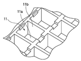
本発明の一実施形態に係る電気接続箱1は、図1に示すように、電気接続箱1の合成樹脂製の筐体表面に、ヒューズを上方から挿入可能なヒューズキャビティ11を複数箇所に備えており、電気接続箱1の筐体内部には、各種電気部品や、各種電気回路、及びそれらの電気部品や電気回路、並びにヒューズを電気的に接続する配線(電気部品、電気回路、配線については、図1には図示せず。)を備えている。
図2および図3に示すように、ヒューズキャビティ11は、ヒューズキャビティ11の内底部分11a及び内周面11bによって形成される凹部に、ヒューズ2の一部または全てが収容されるように成型される。また、ヒューズキャビティ11の内底部分11aからは、一対のキャビティ端子12が突出している(図6等参照)。一対のキャビティ端子12は、ヒューズキャビティ11にヒューズ2が挿入される際に、ヒューズ2のハウジング21の内部に進入し、ヒューズ2のハウジング21に収容された一対のヒューズ端子22(図4等参照)に接触して、該ヒューズ端子に電気的に接続される。また、ヒューズキャビティ11に挿入されたヒューズ2は、該ヒューズ2のハウジング21の下面がヒューズキャビティ11の内底部分11aに当接することでヒューズキャビティ11における下方への位置決めがなされる。ヒューズ2のハウジング21の下面がヒューズキャビティ11の内底部分11aに当接する具体的な構成については、後述する。
次に、本発明の一実施形態に係る電気接続箱に挿入されるヒューズ2の構造について詳細に説明する。図4に示すように、ヒューズ2は、スローブローヒューズ(すなわち、耐ラッシュ電流型ヒューズ)であって、導体によって形成される一対のヒューズ端子22と、一対のヒューズ端子22の間に位置し、一対のヒューズ端子22を電気的に接続する耐ラッシュ性に優れた可溶体23と、可溶体23を覆うようにヒューズ端子22を収容する、ヒューズ2の外形を形作る合成樹脂製のハウジング21と、を含んで構成される。
ハウジング21は、有色透明な絶縁性の合成樹脂材料等で形成されている。ハウジング21は、透明材料で構成されているので、該ハウジング21に収容された可溶体23の溶断の有無をハウジング21の上面、側面、下面から目視で確認することができる。ハウジング21の上端側部には、係合部21aが形成されており、係合部21aは、ヒューズ2をヒューズキャビティ11に挿入した際に、ヒューズキャビティ11に形成された係合溝17に嵌め込まれる。ヒューズキャビティ11に挿入されたヒューズ2は、係合部21aがヒューズキャビティ11の係合溝17に嵌め込まれることによってもヒューズキャビティ11における下方への位置決めがなされる。また、ヒューズ2がヒューズキャビティ11に挿入される際に、一対のキャビティ端子12をハウジング21の内部に導くために、ハウジング21の下面21bには開口部21cが、そしてハウジングの内部には一対のキャビティ端子12が進入する挿入路21dが、それぞれ形成されている。
各ヒューズ端子22はそれぞれ、挿入路21dに挿入されるキャビティ端子12を狭持可能な一対の可動腕部22aと、各可動腕部22aの先端に設けられ、ヒューズ端子22をキャビティ端子12に確実に接触させるための湾曲状の狭持部22bと、一対の可動腕部22aが延設される根元部22cと、を備えた所謂音叉状端子である。ヒューズ端子22は、挿入路21dに挿入されたキャビティ端子12がヒューズ端子22の狭持部22bに接触することによって、キャビティ端子12に電気的に接続される。なお、本発明の一実施形態において、ヒューズ端子22は音叉状端子であるが、音叉状端子に限定されるものではなく、様々な形状の端子を適用することができる(例えば、特開平8-185790号公報の図1,図9、等参照)。
可溶体23は、亜鉛、鉛、銀、又は、それらを主成分とする合金、などの材料によって構成され、その一端が一方のヒューズ端子22の根元部22cに接続され、その他端が他方のヒューズ端子22の根元部22cに接続されている。
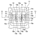
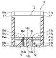
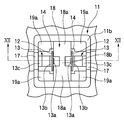
次に、本発明の一実施形態に係る電気接続箱のヒューズキャビティ11の構造について詳細に説明する。図5および図6に示すように、ヒューズキャビティ11は、ヒューズキャビティ11の内底部分11aから突出した一対のキャビティ端子12と、各キャビティ端子12を固定するための端子支持体13と、キャビティ端子12の下端を内底部分11aの下方に収容する収容溝14と、ヒューズキャビティ11の内底部分11aの一部を形成する非突出部15と、ヒューズキャビティ11の内底部分11aの一部を形成する、上面が非突出部15よりも上方に位置する突出部16と、ヒューズ2をヒューズキャビティ11に挿入した際にヒューズ2の係合部21aを嵌め込むための係合溝17と、を備える。
キャビティ端子12は、所謂雄タブ端子であって、当該キャビティ端子12には、ヒューズ2がヒューズキャビティ11に挿入される際に、ハウジング21の開口部21cを通過してハウジング21の挿入路21dに進入し、該挿入路21dに収容される。挿入路21dに挿入されたキャビティ端子12は、ヒューズ端子22の狭持部22bに接触することによって、ヒューズ端子22に電気的に接続される。なお、本発明の一実施形態では、ヒューズ2のヒューズ端子22が所謂音叉状端子であって、ヒューズキャビティ11のキャビティ端子12がヒューズ端子22の音叉状部分に進入する構成について説明するが、ヒューズ端子22とキャビティ端子12の構成が逆になってもよい。すなわち、キャビティ端子12を所謂音叉状端子とし、そしてヒューズ端子22を所謂雄タブ端子とした構成であってもよい。
端子支持体13は、キャビティ端子12に設けられた孔に挿通させて該キャビティ端子12を固定する支持突起13aと、支持突起13aが挿通したキャビティ端子12を受け止める止め具13bと、一端に支持突起13aと止め具13bが延設され、他端がヒューズキャビティ11の筐体に固定された支持棒13cと、を備える。キャビティ端子12の下端を収容溝14に収容する際に、キャビティ端子12が止め具13bに接触するまで当該キャビティ端子12に設けられた孔に支持突起13aを挿通させることによって、キャビティ端子12は、ヒューズキャビティ11の内底部分11aから突出するように固定される。
非突出部15は、ヒューズキャビティ11の内底部分11aの一部を構成し、ヒューズキャビティ11の内周面11bによって形成される4つの隅部15a、及び、収容溝14と後述する台座16aと後述する突条16bによって囲まれる中央部15b、によって構成される。
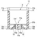
また、突出部16は、ヒューズキャビティ11の内底部分11aの一部を構成し、ヒューズキャビティ11の4つの内周面11bのうちの、一対のキャビティ端子12が並ぶ向きに対して垂直な方向に向き合う2面にそれぞれ隣接する2つの台座16aと、長手方向のそれぞれの端部が2つの台座16aに一体成型された突条16bと、によって構成される。突条16bは、一対のキャビティ端子12の間に位置するように設けられ、特に、ヒューズ2をヒューズキャビティ11に挿入した際にヒューズ2の可溶体23の真下に位置するように設けられる。台座16aの上面16cと突条16bの上面16dは、同一平面上に形成され、それら上面の位置は、非突出部15を構成する隅部15aの上面15cと中央部15bの上面15dよりも上方にある。このため、図7に示すようにヒューズ2をヒューズキャビティ11に挿入した際には、台座16aの上面16cと突条16bの上面16dがヒューズ2のハウジング21の下面21bに当接し、一方、隅部15aの上面15cと中央部15bの上面15dはヒューズ2のハウジング21の下面21bに当接せず、ヒューズ2のハウジング21の下面21bとの間には空隙15eが形成される。したがって、ヒューズキャビティ11の内底部分11aに当接するヒューズ2のハウジング21の下面21bの面積は、台座16aの上面16cと突条16bの上面16dによって形成される面の面積に限られる。
係合溝17は、ヒューズ2をヒューズキャビティ11に挿入した際に台座16aの上面16cと突条16bの上面16dがヒューズのハウジング21の下面21bに当接することを想定し、内周面11bにおける、台座16aの上面16cと突条16bの上面16dから、ヒューズ2のハウジング21の下面21bから係合部21aまでの長さ分だけ上方の位置に設けられる。これにより、台座16aの上面16cと突条16bの上面16dがヒューズのハウジング21の下面21bに当接する場合であっても、ヒューズ2の係合部21aは、ヒューズキャビティ11の係合溝17に嵌め込まれる。
図5、図6、及び図7を参照して説明したヒューズキャビティ11の内底部分11aが、ヒューズ2のハウジング21の下面21bに当接する面積を比較するために、続いて、参考例として、突出部を備えていないヒューズキャビティの構造について図8~図10を参照して説明する。なお、内底部分11a以外のヒューズキャビティ11の各部位、及び、ヒューズ2の各部位については、図4から図7を参照して説明したとおりであるため、説明を省略する。
図8、図9、及び図10に示すヒューズキャビティ11の内底部分11aは、ヒューズキャビティ11の内周面11bによって形成される4つの隅部11c、一対のキャビティ端子12が並ぶ向きに対して垂直な方向に向き合う2面にそれぞれ隣接する2つの台座11dと、長手方向のそれぞれの端部が2つの台座16aに一体成型された突条11eと、によって構成される。ヒューズキャビティ11の内底部分11aは、上述した突出部16を備えておらず、隅部11c、台座11d、突条11eによって構成されるヒューズキャビティ11の内底部分11aの上面11fは、全面が同一平面上に形成される。
ヒューズキャビティ11の内底部分11aの上面11fが同一平面上に形成されることから、ヒューズキャビティ11の内底部分11aは、図10に示すようにヒューズ2をヒューズキャビティ11に挿入した際、ヒューズキャビティ11の内底部分11aの上面11f全面がヒューズ2のハウジング21の下面21bに当接することになる。したがって、ヒューズキャビティ11の内底部分11aに当接するヒューズ2のハウジング21の下面21bの面積は、図5、図6、及び図7を参照して説明した、ヒューズキャビティ11の内底部分11aに当接するヒューズ2のハウジング21の下面21bの面積に比べて、大きくなる。
以上、本発明の一実施形態に係る電気接続箱のヒューズキャビティ11は、ヒューズキャビティ11の内底面から上方に延長するように該内底面に形成された突出部16の上面が、ヒューズ2のハウジング21の下面21bに当接し、そして当該突出部16によりヒューズキャビティ11の内底面とヒューズ2のハウジング21の下面21bとの間に空隙15eが形成される。そのため、可溶体の放熱や溶断した該可溶体の付着によって、ヒューズのハウジングの、ヒューズキャビティへの挿入方向前側に位置する部分が溶損した場合であっても、ヒューズキャビティの、ハウジングの溶損した部分と接着する部分の面積を小さく抑えることができる。従って、ハウジングが溶損したヒューズをヒューズキャビティから容易に取り出すことができる。
また、本発明の一実施形態に係る電気接続箱のヒューズキャビティ11において、突出部16の突条16bが、ヒューズキャビティ11の上面視で、キャビティ端子12の間に位置するようにヒューズキャビティ11の内底部分11aに設けられ、且つヒューズキャビティ11に挿入されている状態のヒューズ2の可溶体23の真下に位置する。この突条16bの上面16dとヒューズキャビティの内周面11bとの協働により、ヒューズ2を電気接続箱1に収容した際に、ヒューズ2のハウジング21のバランスの良い安定した支持ができる。
なお、上述した本発明の一実施形態に係る電気接続箱では、ヒューズキャビティ11の内底部分11aがその内底面から上方に延長するように該内底面に形成された突出部16を有する構成について説明したが、ヒューズキャビティ11の内底部分11aがその内底面から下方に窪むように該内底面に形成された凹部を有する構成であっても構わない。この構成を図5、図6、及び図7を参照して説明したヒューズキャビティ11の内底部分11aに適用すると、非突出部15の上面を底面とし、非突出部15の上面と突出部16の上面との高低差を高さとする立体が凹部に相当する。ヒューズキャビティ11の内底部分11aに凹部を設ける構成であっても、ヒューズキャビティ11の内底部分11aに突出部16を設ける構成と同様に、ヒューズキャビティの、ハウジングの溶損した部分と接着する部分の面積を小さく抑えることができる。
なお、上述した本発明の一実施形態に係る電気接続箱では、突出部16の一部である台座16aが、ヒューズキャビティ11の内周面11bに隣接するように設けられ、突出部16の一部である突条16bが、一対のキャビティ端子12の間に位置するように設けられる構成について説明したが、ヒューズキャビティ11の内底部分11aに設けられる突出部16の位置は、これらの位置に限られるものではなく、ヒューズキャビティ11の内底部分11aの任意の位置に設けることができる。一対のキャビティ端子12の位置、端子支持体13の位置、及び収容溝14の位置を考慮して、適宜設けられることが好ましい。
以下、上述した本発明の一実施形態に係る電気接続箱とは異なる位置に突出部を設けた場合について図11~図13を参照して説明する。なお、内底部分11aを形成する非突出部及び突出部以外のヒューズキャビティ11の各部位、及び、ヒューズ2の各部位については、図4から図7を参照して説明したとおりであるため、説明を省略する。
ヒューズキャビティ11の内底部分11aは、非突出部18と、突出部19とにより形成される。非突出部18は、ヒューズキャビティ11の内底部分11aの一部を構成し、ヒューズキャビティ11の4つの内周面11bのうちの、一対のキャビティ端子12が並ぶ向きに対して垂直な方向に向き合う2面にそれぞれ隣接する2つの台座18aと、長手方向のそれぞれの端部が2つの台座18aに一体成型された突条18bと、により構成される。また、突出部19は、ヒューズキャビティ11の4つの内周面11bによって形成される4つの隅部19aによって構成される。4つの隅部19aの上面19bは、同一平面上に形成され、その上面19bの位置は、2つの台座18aの上面18cと突条18bの上面18dよりも上方にある。このため、図13に示すようにヒューズ2をヒューズキャビティ11に挿入した際には、4つの隅部19aの上面19bがヒューズ2のハウジング21の下面21bに当接し、一方、2つの台座18aの上面18cと突条18bの上面18dはヒューズ2のハウジング21の下面21bに当接せず、ヒューズ2のハウジング21の下面21bとの間には空隙18eが形成されることになる。したがって、ヒューズキャビティ11の内底部分11aに当接するヒューズ2のハウジング21の下面21bの面積は、4つの隅部19aの上面19bの面積に限られる。
上述のように、本発明の他の実施形態に係る電気接続箱のヒューズキャビティ11は、台座18aの上面18cまたは突条18bの上面18dと、ヒューズ2のハウジング21の下面21bと、の間に空隙18eが形成されるように、4つの隅部19aが内底部分11aに突設されている。ヒューズ2のハウジング21が溶損する際には可溶体23に近いところから溶損するが、ヒューズ2が挿入された状態でヒューズキャビティ11を上面視したときに可溶体23から遠くに離れた箇所に4つの隅部19aが位置するため、ヒューズ2のハウジング21の下面21bのうちのより溶損し難い箇所に突出部19の上面が当接されることになる。従って、溶損したハウジング21が突出部16の上面に接着することすら防止することができる。
以上、本発明の電気接続箱によれば、可溶体の放熱や溶断した該可溶体の付着によって、ヒューズのハウジングの、ヒューズキャビティへの挿入方向前側に位置する部分が溶損した場合であっても、ヒューズキャビティの、ハウジングの溶損した部分と接着する部分の面積を小さく抑えることができる。従って、ハウジングが溶損したヒューズをヒューズキャビティから容易に取り出すことができる。よって、本発明によれば、ヒューズ交換に係る作業負担を低減することができる。
本発明の電気接続箱は、ハウジングがより溶損されるスローブローヒューズが挿入された場合に、より顕著に、その溶損したハウジングがヒューズキャビティの内底面に接着することを抑制することができる。
本出願は、2008年1月23日出願の日本特許出願(特願2008-013063)に基づくものであり、その内容はここに参照として取り込まれる。
本発明の電気接続箱によれば、ヒューズキャビティの、ハウジングの溶損した部分と接着する部分の面積を小さく抑えることができるので、ハウジングが溶損したヒューズをヒューズキャビティから容易に取り出すことができ、よって、ヒューズ交換に係る作業負担を低減することができる。
Claims (6)
- 一対のヒューズ端子と、該ヒューズ端子間を電気的に接続する可溶体と、該可溶体を覆うように前記ヒューズ端子を収容する合成樹脂製のハウジングと、を有するヒューズが、上方から挿入可能な合成樹脂製のヒューズキャビティと、
該ヒューズキャビティに前記ヒューズが挿入された際に前記ヒューズ端子と接触して電気的に接続される一対のキャビティ端子と、
を備え、
前記ヒューズキャビティに挿入された前記ヒューズのハウジングの下面が前記ヒューズキャビティの内底部分に当接することで前記ヒューズの前記ヒューズキャビティにおける下方への位置決めがなされる電気接続箱であって、
前記内底部分が、その内底面から上方に延長するように該内底面に形成された突出部を有しており、
前記突出部の上面が前記ハウジングの前記下面に当接し、そして
前記突出部により前記内底面と前記ハウジングの前記下面との間に空隙が形成されている電気接続箱。 - 前記突出部が、前記ヒューズキャビティの上面視で、前記キャビティ端子の間に位置するように前記内底面に設けられ、且つ前記ヒューズキャビティに収容されている状態の前記ヒューズの可溶体の真下に位置する請求項1に記載の電気接続箱。
- 前記突出部が、前記ヒューズキャビティに収容されている状態の前記ヒューズのハウジングの前記可溶体の真下に位置する部分の下面と、前記ヒューズキャビティの内底面との間に前記空隙を形成するように前記内底面に突設されている請求項1に記載の電気接続箱。
- 前記ヒューズがスローブローヒューズである請求項1に記載の電気接続箱。
- 前記ヒューズがスローブローヒューズである請求項2に記載の電気接続箱。
- 前記ヒューズがスローブローヒューズである請求項3に記載の電気接続箱。
Priority Applications (3)
| Application Number | Priority Date | Filing Date | Title |
|---|---|---|---|
| US12/863,797 US8339236B2 (en) | 2008-01-23 | 2009-01-21 | Electric connection box |
| CN200980102734.8A CN101926066B (zh) | 2008-01-23 | 2009-01-21 | 电气接线箱 |
| EP09703687.5A EP2242157B1 (en) | 2008-01-23 | 2009-01-21 | Electric connection box |
Applications Claiming Priority (2)
| Application Number | Priority Date | Filing Date | Title |
|---|---|---|---|
| JP2008-013063 | 2008-01-23 | ||
| JP2008013063A JP5187941B2 (ja) | 2008-01-23 | 2008-01-23 | 電気接続箱 |
Publications (1)
| Publication Number | Publication Date |
|---|---|
| WO2009093613A1 true WO2009093613A1 (ja) | 2009-07-30 |
Family
ID=40901121
Family Applications (1)
| Application Number | Title | Priority Date | Filing Date |
|---|---|---|---|
| PCT/JP2009/050885 Ceased WO2009093613A1 (ja) | 2008-01-23 | 2009-01-21 | 電気接続箱 |
Country Status (5)
| Country | Link |
|---|---|
| US (1) | US8339236B2 (ja) |
| EP (1) | EP2242157B1 (ja) |
| JP (1) | JP5187941B2 (ja) |
| CN (1) | CN101926066B (ja) |
| WO (1) | WO2009093613A1 (ja) |
Families Citing this family (6)
| Publication number | Priority date | Publication date | Assignee | Title |
|---|---|---|---|---|
| WO2013089288A1 (ko) * | 2011-12-13 | 2013-06-20 | 볼보 컨스트럭션 이큅먼트 에이비 | 휴즈 오용에 따른 화재 방지 및 보호 시스템 |
| GB2486612B (en) * | 2012-03-23 | 2012-10-17 | Lucy & Company Ltd W | Fuse Holder |
| US8961197B2 (en) | 2012-06-08 | 2015-02-24 | Lear Corporation | Fuse housing assembly |
| JP6601330B2 (ja) * | 2016-07-01 | 2019-11-06 | 住友電装株式会社 | 暗電流回路の断続構造を備えた電気接続箱 |
| CN110224368A (zh) * | 2019-07-04 | 2019-09-10 | 淮南常力达电气有限公司 | 一种散热防爆的高压电缆分支箱 |
| KR102820188B1 (ko) | 2020-05-13 | 2025-06-13 | 주식회사 엘지에너지솔루션 | 단락 방지용 퓨즈박스 브라켓이 구비된 배터리 팩 |
Citations (4)
| Publication number | Priority date | Publication date | Assignee | Title |
|---|---|---|---|---|
| JPH08185790A (ja) | 1994-12-28 | 1996-07-16 | Yazaki Corp | ヒュージブルリンク |
| JP2001351502A (ja) * | 2001-04-06 | 2001-12-21 | Yazaki Corp | ヒューズボックス |
| JP2004064871A (ja) | 2002-07-29 | 2004-02-26 | Furukawa Electric Co Ltd:The | 電気接続箱 |
| JP2005209509A (ja) * | 2004-01-23 | 2005-08-04 | Yazaki Corp | 電気接続箱、ヒューズ変換アダプタ及び中継端子 |
Family Cites Families (30)
| Publication number | Priority date | Publication date | Assignee | Title |
|---|---|---|---|---|
| US4670729A (en) * | 1986-06-03 | 1987-06-02 | Littelfuse, Inc. | Electrical fuse |
| JPH01150250U (ja) | 1988-04-11 | 1989-10-17 | ||
| JPH0731486Y2 (ja) * | 1989-12-28 | 1995-07-19 | 矢崎総業株式会社 | カセットヒューズ接続箱 |
| JP2563313Y2 (ja) * | 1990-08-06 | 1998-02-18 | 矢崎総業株式会社 | 電気接続箱 |
| JP2563311Y2 (ja) * | 1990-09-12 | 1998-02-18 | 矢崎総業株式会社 | ヒューズボックス |
| US5171293A (en) * | 1991-12-05 | 1992-12-15 | Yazaki Corporation | Fuse box assembly |
| JP2634524B2 (ja) * | 1991-12-06 | 1997-07-30 | 矢崎総業株式会社 | 暗電流ヒューズの断続機構 |
| JP2879811B2 (ja) * | 1993-07-02 | 1999-04-05 | 矢崎総業株式会社 | 暗電流ヒューズの断続機構及びそれを備えた電気接続箱 |
| JP3083061B2 (ja) * | 1995-01-20 | 2000-09-04 | 矢崎総業株式会社 | ヒューズ接続構造 |
| US5662496A (en) * | 1995-06-07 | 1997-09-02 | Yazaki Corporation | Fuse junction box |
| JPH09171765A (ja) * | 1995-12-20 | 1997-06-30 | Yazaki Corp | ヒューズボックス |
| JP3216791B2 (ja) * | 1996-05-24 | 2001-10-09 | 矢崎総業株式会社 | 電子ユニットボックスの排水構造 |
| US6089918A (en) * | 1997-06-30 | 2000-07-18 | Yazaki Corporation | Adapter for electrical circuit components |
| US5886612A (en) * | 1997-10-20 | 1999-03-23 | Littelfuse, Inc. | Female fuse housing |
| JP2001250466A (ja) * | 2000-03-03 | 2001-09-14 | Taiheiyo Seiko Kk | ヒューズ素子及びヒューズ取付装置 |
| JP3242095B2 (ja) * | 2000-05-16 | 2001-12-25 | 矢崎総業株式会社 | ヒューズ |
| GB2385723B (en) * | 2002-02-21 | 2004-07-07 | Yazaki Corp | Fuse and fuse production method |
| US6922332B2 (en) * | 2002-04-10 | 2005-07-26 | Furukawa Electric Co., Ltd. | Electric connection box |
| JP2003339109A (ja) * | 2002-05-20 | 2003-11-28 | Yazaki Corp | 端子支持孔構造 |
| JP4047073B2 (ja) * | 2002-05-31 | 2008-02-13 | 矢崎総業株式会社 | 電気接続箱のキャビティ構造 |
| JP2004032839A (ja) * | 2002-06-21 | 2004-01-29 | Sumitomo Wiring Syst Ltd | 電気接続箱 |
| US7612646B2 (en) * | 2003-04-04 | 2009-11-03 | Yazaki Corporation | Fuse cavity structure and electric connection box |
| US7077667B2 (en) * | 2003-04-22 | 2006-07-18 | Yazaki Corporation | Electrical junction box |
| US6781503B1 (en) * | 2003-04-24 | 2004-08-24 | Yazaki Corporation | Fuse assembly for differently structured fuses |
| JP4098680B2 (ja) * | 2003-07-31 | 2008-06-11 | 矢崎総業株式会社 | ヒューズキャビティおよび電気接続箱 |
| JP4238783B2 (ja) * | 2004-06-08 | 2009-03-18 | 住友電装株式会社 | 電気接続箱のヒューズ装着構造 |
| JP2005353465A (ja) * | 2004-06-11 | 2005-12-22 | Sumitomo Wiring Syst Ltd | 電気接続箱のヒュージブルリンク装着構造 |
| JP4311334B2 (ja) * | 2004-10-15 | 2009-08-12 | 住友電装株式会社 | 電気接続箱 |
| JP3841103B1 (ja) * | 2005-07-14 | 2006-11-01 | 住友電装株式会社 | 予備ヒューズ収容部を備えた電気接続箱 |
| US7445509B2 (en) * | 2006-06-14 | 2008-11-04 | Cooper Technologies Company | In-line fuse holder for female fuse |
-
2008
- 2008-01-23 JP JP2008013063A patent/JP5187941B2/ja active Active
-
2009
- 2009-01-21 CN CN200980102734.8A patent/CN101926066B/zh active Active
- 2009-01-21 WO PCT/JP2009/050885 patent/WO2009093613A1/ja not_active Ceased
- 2009-01-21 EP EP09703687.5A patent/EP2242157B1/en active Active
- 2009-01-21 US US12/863,797 patent/US8339236B2/en active Active
Patent Citations (4)
| Publication number | Priority date | Publication date | Assignee | Title |
|---|---|---|---|---|
| JPH08185790A (ja) | 1994-12-28 | 1996-07-16 | Yazaki Corp | ヒュージブルリンク |
| JP2001351502A (ja) * | 2001-04-06 | 2001-12-21 | Yazaki Corp | ヒューズボックス |
| JP2004064871A (ja) | 2002-07-29 | 2004-02-26 | Furukawa Electric Co Ltd:The | 電気接続箱 |
| JP2005209509A (ja) * | 2004-01-23 | 2005-08-04 | Yazaki Corp | 電気接続箱、ヒューズ変換アダプタ及び中継端子 |
Non-Patent Citations (1)
| Title |
|---|
| See also references of EP2242157A4 * |
Also Published As
| Publication number | Publication date |
|---|---|
| US8339236B2 (en) | 2012-12-25 |
| CN101926066A (zh) | 2010-12-22 |
| EP2242157A1 (en) | 2010-10-20 |
| US20100289611A1 (en) | 2010-11-18 |
| JP5187941B2 (ja) | 2013-04-24 |
| EP2242157B1 (en) | 2018-11-28 |
| JP2009177926A (ja) | 2009-08-06 |
| CN101926066B (zh) | 2014-03-12 |
| EP2242157A4 (en) | 2014-04-30 |
Similar Documents
| Publication | Publication Date | Title |
|---|---|---|
| JP5187941B2 (ja) | 電気接続箱 | |
| CN101937813B (zh) | 带有表面安装端帽和改进连接性的微型熔断器 | |
| US7292130B2 (en) | Fusible link and battery fuse unit containing the fusible link | |
| CN103493170B (zh) | 熔断器 | |
| BRPI0015871B1 (pt) | fusível do tipo lâmina | |
| JP6370586B2 (ja) | 電池接続体、及び、それを備えたバッテリパック | |
| JP2015056994A (ja) | 電気接続箱 | |
| EP2768007B1 (en) | Blade-type fuse | |
| WO2024127680A1 (ja) | ヒューズ、及び当該ヒューズの製造方法 | |
| JP6309303B2 (ja) | 電気接続箱 | |
| JP2000030600A (ja) | 多極形ヒューズ素子 | |
| JP7041185B2 (ja) | ヒューズユニット | |
| US20080272877A1 (en) | Fuse Device | |
| JP7364366B2 (ja) | 電流遮断構造 | |
| JP5878028B2 (ja) | ブレードヒューズ | |
| KR102098704B1 (ko) | 퓨즈 | |
| CN100593890C (zh) | 熔丝腔结构和电气连接箱 | |
| WO2021020255A1 (ja) | 電子モジュール | |
| JP2009129671A (ja) | ヒューズ、及び、ヒューズの取付構造 | |
| JP2005209509A (ja) | 電気接続箱、ヒューズ変換アダプタ及び中継端子 | |
| JP7198511B2 (ja) | ヒューズ | |
| US9418813B2 (en) | Fuse assembly | |
| KR100920246B1 (ko) | 휴즈 장착부재 | |
| JP7123482B2 (ja) | ヒュージブルリンクユニット | |
| JP2002313212A (ja) | ヒューズハウジング |
Legal Events
| Date | Code | Title | Description |
|---|---|---|---|
| WWE | Wipo information: entry into national phase |
Ref document number: 200980102734.8 Country of ref document: CN |
|
| 121 | Ep: the epo has been informed by wipo that ep was designated in this application |
Ref document number: 09703687 Country of ref document: EP Kind code of ref document: A1 |
|
| WWE | Wipo information: entry into national phase |
Ref document number: 2009703687 Country of ref document: EP |
|
| WWE | Wipo information: entry into national phase |
Ref document number: 12863797 Country of ref document: US |
|
| NENP | Non-entry into the national phase |
Ref country code: DE |