WO2009095950A1 - クランプ装置 - Google Patents
クランプ装置 Download PDFInfo
- Publication number
- WO2009095950A1 WO2009095950A1 PCT/JP2008/000108 JP2008000108W WO2009095950A1 WO 2009095950 A1 WO2009095950 A1 WO 2009095950A1 JP 2008000108 W JP2008000108 W JP 2008000108W WO 2009095950 A1 WO2009095950 A1 WO 2009095950A1
- Authority
- WO
- WIPO (PCT)
- Prior art keywords
- tip side
- side portion
- piezoelectric element
- annular
- cross
- Prior art date
- Legal status (The legal status is an assumption and is not a legal conclusion. Google has not performed a legal analysis and makes no representation as to the accuracy of the status listed.)
- Ceased
Links
Images


Classifications
-
- F—MECHANICAL ENGINEERING; LIGHTING; HEATING; WEAPONS; BLASTING
- F16—ENGINEERING ELEMENTS AND UNITS; GENERAL MEASURES FOR PRODUCING AND MAINTAINING EFFECTIVE FUNCTIONING OF MACHINES OR INSTALLATIONS; THERMAL INSULATION IN GENERAL
- F16D—COUPLINGS FOR TRANSMITTING ROTATION; CLUTCHES; BRAKES
- F16D49/00—Brakes with a braking member co-operating with the periphery of a drum, wheel-rim, or the like
- F16D49/08—Brakes with a braking member co-operating with the periphery of a drum, wheel-rim, or the like shaped as an encircling band extending over approximately 360 degrees
-
- H—ELECTRICITY
- H02—GENERATION; CONVERSION OR DISTRIBUTION OF ELECTRIC POWER
- H02K—DYNAMO-ELECTRIC MACHINES
- H02K7/00—Arrangements for handling mechanical energy structurally associated with dynamo-electric machines, e.g. structural association with mechanical driving motors or auxiliary dynamo-electric machines
- H02K7/10—Structural association with clutches, brakes, gears, pulleys or mechanical starters
- H02K7/102—Structural association with clutches, brakes, gears, pulleys or mechanical starters with friction brakes
-
- F—MECHANICAL ENGINEERING; LIGHTING; HEATING; WEAPONS; BLASTING
- F16—ENGINEERING ELEMENTS AND UNITS; GENERAL MEASURES FOR PRODUCING AND MAINTAINING EFFECTIVE FUNCTIONING OF MACHINES OR INSTALLATIONS; THERMAL INSULATION IN GENERAL
- F16D—COUPLINGS FOR TRANSMITTING ROTATION; CLUTCHES; BRAKES
- F16D2121/00—Type of actuator operation force
- F16D2121/18—Electric or magnetic
- F16D2121/28—Electric or magnetic using electrostrictive or magnetostrictive elements, e.g. piezoelectric elements
Definitions
- the present invention relates to a clamping device configured to release a clamping force or a braking force acting on a rotating shaft such as a motor output shaft by using a laminated piezoelectric element.
- Patent Document 1 proposes a brake device that applies a clamping force or a braking force to a rotating shaft by using expansion and contraction of a laminated piezoelectric element instead of a magnetic attraction force.
- the brake shoe of the inner drum pressed against the inner peripheral surface of the outer drum extends the stacked piezoelectric element.
- the inner drum moves away from the inner peripheral surface of the cylindrical member, and thereby the brake force is released.
- An object of the present invention is to propose a small and compact clamping device that can apply and release a clamping force or a braking force to a rotating shaft using a laminated piezoelectric element from the outside of the rotating shaft.
- the present invention releases a clamping force or a braking force acting on a rotating shaft by bending a flexible cylindrical portion in a radial direction using a multilayer piezoelectric element.
- a clamping device The flexible tube portion is formed with a mounting flange extending radially outward at the rear end in the axial direction, and the cross-sectional shape of the tip side portion in the axial direction is a polygon,
- An annular part is arranged in a state surrounding the tip side part of the cylindrical part,
- the multilayer piezoelectric element is assembled to the annular part so that the diameter of the annular part expands and contracts with expansion and contraction of the multilayer piezoelectric element,
- the annular portion and the tip side portion of the tubular portion are connected at at least two locations in the circumferential direction, and the tubular portion is expanded by the annular portion that expands outward as the stacked piezoelectric element expands.
- the tip side portion of the portion is pulled outward, and the cross-sectional shape of the tip side portion is deformed from a polygon to a perfect circle or a shape close to a perfect circle,
- the peripheral length of the inner peripheral surface of the tip side portion of the cylindrical portion is longer than the peripheral length of the circular outer peripheral surface of the rotating shaft.
- the tip end portion of the polygonal cross section of the cylindrical portion is fixed to the outer periphery of the rotating shaft. That is, the rotation shaft is disposed in a state of penetrating the cylindrical portion, and the tip side portion of the polygonal cross section is bent by the circular rotation shaft so as to be substantially circular. As a result, a state is formed in which the elastic restoring force at the tip end portion of the cylindrical portion acts as a clamping force or a braking force on the outer peripheral surface of the rotating shaft.
- the annular portion When the voltage application to the multilayer piezoelectric element is released, the annular portion is reduced inward, and the tensile force that has pulled the tip side portion of the cylindrical portion outward is released. As a result, it returns to the clamped state or the braked state in which the elastic restoring force that the tip side portion of the cylindrical portion tries to return to the polygonal cross section acts on the outer peripheral surface of the rotating member again.
- the annular portion is connected in the circumferential direction alternately with the number of the laminated piezoelectric elements and the connecting pieces corresponding to the number of corners of the regular polygon, and the expansion and contraction direction of each laminated piezoelectric element is the annular portion. It is sufficient to be in the circumferential direction. Moreover, what is necessary is just to connect each connection piece to the site
- an inner cylinder having a circular cross section may be fitted into the polygonal cross section inside the tip side portion of the cylindrical portion, and a rotating shaft may be passed through the inside.
- the peripheral length of the inner peripheral surface of the inner cylinder may be made longer than the peripheral length of the circular outer peripheral surface of the rotating shaft.
- the rotation shaft is passed through the tip side portion of the cylindrical portion formed in advance in a polygonal cross section or the inner shaft fitted inside the tip side portion of the cylinder portion is passed.
- the tip side portion is forcibly bent so as to be circular outward in the radial direction, thereby generating a clamping force or a braking force for the rotating shaft.
- the annular part arranged so as to surround the tip side part spreads outward, the tip side part is pulled outward, and the clamping force or the braking force against the rotating shaft is released. Or it is reduced.
- annular shape in which a cylindrical portion (or a cylindrical portion and an inner cylinder) fitted to the rotating shaft and a laminated piezoelectric element arranged so as to surround the cylindrical portion are incorporated on the outer peripheral side of the rotating shaft. It is sufficient to arrange only the part. Further, since the annular portion may be disposed at a portion within the outer diameter of the mounting flange for fixing the cylindrical portion to the fixing member side, the space occupied in the radial direction of the rotating shaft can be reduced. Therefore, a compact and compact configuration of the clamping device can be realized.
- FIG. 1 It is a schematic perspective view which shows the principal part of the clamp apparatus to which this invention is applied, The clamp state is shown. It is a schematic plan view of the clamp apparatus of FIG. It is a schematic sectional drawing of the clamp apparatus of FIG. It is a schematic plan view which shows the unclamp state of the clamp apparatus of FIG. It is a top view which shows the initial shape of the brake ring of the clamp apparatus of FIG.
- FIG. 1 is a schematic perspective view showing the main part of the clamping device according to the present embodiment, and shows its clamping state.
- FIG. 2 is a schematic plan view thereof
- FIG. 3 is a schematic sectional view thereof.
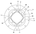
- the clamp apparatus 1 has the metal ring ring 3 of the top hat shape fixed to the circular outer peripheral surface 2a of the rotating shaft 2 to be clamped.
- the brake ring 3 includes a cylindrical portion 4 that can be bent in the radial direction, a disc-shaped mounting flange portion 5 that extends outward from the rear end opening edge 4 a of the cylindrical portion 4 in the radial direction, and a cylindrical portion 4.
- an annular portion 6 disposed so as to surround the outer periphery on the tip opening edge 4b side.
- FIG. 5 is a schematic plan view showing the brake ring 3 before being attached to the rotating shaft 2.
- the cylindrical portion 4 has a circular cross section on the side of the rear end opening edge 4a, and the front end side portion 4c has a regular square cross section as a whole, and each of the four corner portions 4d is rounded. Yes.
- the cross-sectional shape of the portion between the rear end opening edge 4a of the circular cross section in the cylindrical portion 4 and the front end side portion 4c of the regular square cross section gradually changes from a circular shape to a regular tetragon.
- the circumferential length of the inner circumferential surface of the cylindrical portion 4 is set to be slightly longer than the circumferential length of the circular outer circumferential surface 2 a of the rotating shaft 2.
- the distal end side portion 4c of the cylindrical portion 4 is elastically deformed to a state close to a perfect circle by the circular outer peripheral surface 2a of the rotating shaft 2, as shown in FIG.
- the tip side portion 4c is pressed against the circular outer peripheral surface 2a of the rotary shaft 2 with a slight gap remaining in the four corner portions 4d of the tip side portion 4c.
- the rotating shaft 2 is formed with a clamped state in which a predetermined clamping force or braking force is applied by the tip side portion 4c.
- the mounting flange portion 5 continuing to the rear end opening edge 4a of the cylindrical portion 4 of this shape has screw holes 5a formed at regular angular intervals along the outer peripheral edge portion. As shown in FIG. 3, the mounting flange portion 5 is fixed to the fixed member 8 by the fixing screw 7.
- the annular portion 6 is disposed so as to surround the tip side portion 4c of the regular square cross section in the cylindrical portion 4 in a coaxial state.
- the annular portion 6 includes four laminated piezoelectric elements 11 each having an elongated rectangular parallelepiped shape, and four metal connecting pieces 12 sandwiched between the four laminated piezoelectric elements 11 and connected in the circumferential direction. I have.
- Each connecting piece 12 has the same shape, and has an arc portion 12a having a constant thickness curved at approximately 90 degrees, and an arm portion 12b extending from the center of the inner peripheral surface of the arc portion 12a toward the arc center. It has.
- the distal end (inner end) of the arm portion 12b is connected to or continuous with the middle position of the four corner portions 4d in the distal end side portion 4c of the cylindrical portion 4.
- the laminated piezoelectric element 11 expands and contracts in the circumferential direction of the annular portion 6.
- each laminated piezoelectric element 11 expands and the annular portion 6 spreads outward as a whole. That is, since each connecting piece 12 is connected with each laminated piezoelectric element 11 interposed therebetween, when the laminated piezoelectric element 11 is extended, the diameter of the annular portion 6 is increased by an amount corresponding to the total amount of extension.
- FIG. 4 shows a state in which each laminated piezoelectric element 11 is stretched by applying a voltage.
- the laminated piezoelectric element 11 extends, the annular portion 6 spreads outward as a whole, and each connecting piece 12 that is a component moves slightly outward in the radial direction.
- the portion between the corner portions 4d of the square-shaped front end side portion 4c of the cylindrical portion 4 connected to or integrated with each connecting piece 12 is pulled outward and elastically deformed.
- tip side part 4c of a regular square is bent by the state of a substantially perfect circle as a whole.
- the peripheral length of the inner peripheral surface of the distal end side portion 4 c is slightly larger than the peripheral length of the circular outer peripheral surface 2 a of the rotating shaft 2. Therefore, the mechanical engagement between the tip side portion 4c bent in a circular shape and the circular outer peripheral surface 2a of the rotary shaft 2 is substantially released, and the clamping force acting on the rotary shaft 2 from the tip side portion 4c. Alternatively, an unclamping state in which the braking force is substantially zero is obtained.
- the clamping force or the clamping force is applied to the rotating shaft 2 by the tip side portion 4 c of the cylindrical portion 4 bent by the rotating shaft 2. It is in the clamped state where the braking force is applied.
- the annular portion 6 expands as a whole, and the tip side portion 4c connected thereto is pulled outward and elastically deformed into a substantially perfect circle. It is done.
- the mechanical engagement between the distal end side portion 4c and the rotary shaft 2 is released, and the state is switched to an unclamped state in which the clamping force or the braking force acting on the rotary shaft 2 is released.
- the distal end side portion 4c of the cylindrical portion 4 is formed in a regular tetragon, but it goes without saying that it may be a regular polygon such as a regular hexagon or a regular octagon.
- the annular portion 6 is formed by sandwiching the number of stacked piezoelectric elements corresponding to the number of corners, the front side portion 4c of the regular polygon is deformed into a perfect circle when the stacked piezoelectric element is extended. It is easy to make.
- a flexible inner cylinder having a circular cross section is formed inside the distal end side portion 4c. And the inner cylinder may be brought into contact with the rotary shaft 2.
- the inner cylinder functions as a brake ring, and the inner cylinder having a circular cross section is fitted into the distal end side portion 4c of the cylindrical section 4 having a regular square cross section and bent into a regular square shape. What is necessary is just to let the rotating shaft 2 pass inside.
Landscapes
- Engineering & Computer Science (AREA)
- General Engineering & Computer Science (AREA)
- Mechanical Engineering (AREA)
- Power Engineering (AREA)
- Braking Arrangements (AREA)
- Clamps And Clips (AREA)
Abstract
クランプ装置(1)の可撓性の筒部(4)の先端側部分(4c)の断面形状は正四角形であり、ここに嵌めた回転軸(2)によって円形に近い形状に変形して当該回転軸(2)に所定のクランプ力を与えている。筒部(4)の先端側部分(4c)を取り囲む状態に配置されている環状部(6)は4個の積層型圧電素子(11)と4個の円弧状の連結片(12)が交互に連結された構成であり、各積層型圧電素子(11)を伸張させると環状部(6)の径が広がり、各連結片(12)に連結されている先端側部分(4c)が外側に引張られて真円となるように変形させられ、当該先端側部分(4c)が回転軸(2)の円形外周面(2a)から離れてクランプ力が解除されたアンクランプ状態に切り替わる。積層型圧電素子を用いて可撓性の筒を半径方向に撓めることにより回転軸に作用しているクランプ力が開放されるクランプ装置を小型でコンパクトに構成できる。
Description
本発明は、積層型圧電素子を利用して、モータ出力軸などの回転軸に作用しているクランプ力あるいはブレーキ力を解除するように構成されたクランプ装置に関する。
モータの出力軸などの回転軸にクランプ力あるいはブレーキ力を加えるクランプ装置あるいはブレーキ装置としては電磁石による磁気吸引力を利用した無励磁動作型電磁ブレーキなどが知られている。また、特許文献1には、磁気吸引力の代わりに積層型圧電素子の伸縮を利用してクランプ力あるいはブレーキ力を回転軸に加えるブレーキ装置が提案されている。当該特許文献1に開示のブレーキ装置では、その図8~図16に描かれているように、外側ドラムの内周面に押し付けられている内側ドラムのブレーキシューが、積層型圧電素子を伸張させると内側ドラムの変形により円筒部材の内周面から離れて内側に引き込められ、これにより、ブレーキ力が開放されるようになっている。
特開2004-60746号公報
本発明の課題は、回転軸の外側から積層型圧電素子を利用して当該回転軸にクランプ力あるいはブレーキ力を印加および解放することのできる小型でコンパクトなクランプ装置を提案することにある。
上記の課題を解決するために、本発明は、積層型圧電素子を用いて可撓性の筒部を半径方向に撓めることにより回転軸に作用しているクランプ力あるいはブレーキ力が解除されるクランプ装置であって、
前記可撓性の筒部は、その軸線方向の後端に半径方向の外方に広がっている取付用フランジが形成され、その軸線方向の先端側部分の断面形状が多角形であり、
前記筒部の前記先端側部分を取り囲む状態に環状部が配置されており、
前記環状部が前記積層型圧電素子の伸縮に伴って径が拡大および縮小するように、前記環状部に前記積層型圧電素子が組み付けられており、
前記環状部と前記筒部の前記先端側部分の間は、これらの周方向における少なくとも2ヶ所の部位で連結され、前記積層型圧電素子が伸張することにより外側に広がった前記環状部によって前記筒部の前記先端側部分が外側に引張られて、当該先端側部分の断面形状が多角形から真円あるいは真円に近い形状に変形するようになっており、
前記筒部の前記先端側部分の内周面の周長は、前記回転軸の円形外周面の周長よりも長いことを特徴としている。
本発明のクランプ装置では、筒部の多角形断面の先端側部分が回転軸の外周に固定される。すなわち、回転軸が筒部を貫通する状態に配置され、円形断面の回転軸によって多角形断面の先端側部分が略円形となるように撓められる。この結果、筒部の先端側部分の弾性復帰力が回転軸の外周面に対してクランプ力あるいはブレーキ力として作用した状態が形成される。
この状態において、積層型圧電素子に電圧を加えて当該積層型圧電素子を伸張させると、環状部が広がり、当該環状部に連結されている先端側部分の部位も外側に引張られ、当該先端側部分が真円あるいは真円に近い形状に変形する。当該先端側部分の内周面の周長は回転軸の円形外周面の周長よりも長いので、当該先端側部分が真円あるいは真円に近い状態に変形すると、当該先端側部分と回転軸の機械的な係合状態が実質的に解除され、回転軸に加わっていたクランプ力あるいはブレーキ力が解除される。この結果、回転軸が回転自在の状態に切り替わる。
積層型圧電素子に対する電圧印加を解除すると、環状部が内側に縮小して筒部の先端側部分を外側に引張っていた引張り力が解除される。この結果、当該筒部の先端側部分が多角形断面に復帰しようとする弾性復帰力が回転部材の外周面に再び作用したクランプ状態あるいはブレーキ状態に戻る。
ここで、前記筒部の先端側部分の断面形状を正多角形として、回転軸の外周面に対して外側から均等にクランプ力あるいはブレーキ力を加えることが望ましい。この場合、前記環状部を、前記正多角形の角数に対応する個数の前記積層型圧電素子と連結片とを交互に周方向に連結し、各積層型圧電素子の伸縮方向が当該環状部の周方向となるようにしておけばよい。また、各連結片を前記筒部の先端側部分における正多角形の角の間の部位にそれぞれ連結しておけばよい。
また、前記筒部の前記先端側部分の内側に、円形断面の内筒を多角形断面に撓めた状態で嵌め込み、この内側に回転軸を通していても良い。この場合には、前記内筒の内周面の周長を前記回転軸の円形外周面の周長よりも長くなるようにしておけばよい。
本発明のクランプ装置では、予め多角形断面に形成された筒部の先端側部分に回転軸を通すことにより、あるいは、筒部の先端側部分の内側の嵌め込んだ内筒に回転軸を通すことにより、当該先端側部分を半径方向の外側に円形となるように強制的に撓め、これにより、回転軸に対するクランプ力あるいはブレーキ力を発生させている。また、積層型圧電素子を伸張させると、先端側部分を取り囲む状態に配置されている環状部が外側に広がり、先端側部分が外方に引張られて、回転軸に対するクランプ力あるいはブレーキ力が開放あるいは低減される。
本発明のクランプ装置では、回転軸の外周側に、回転軸に嵌めた筒部(あるいは、筒部および内筒)と、この筒部を取り囲む状態に配置した積層型圧電素子が組み込まれた環状部のみを配置すればよい。また、環状部は、筒部を固定部材の側に固定するための取付用フランジの外径寸法内の部位に配置すればよいので、回転軸の径方向の占有スペースも少なくて済む。よって、小型でコンパクトな構成のクランプ装置を実現できる。
以下に、図面を参照して、本発明を適用したクランプ装置の実施の形態を説明する。
図1は本実施の形態に係るクランプ装置の主要部分を示す概略斜視図であり、そのクランプ状態を示してある。図2はその概略平面図であり、図3はその概略断面図である。これらの図を参照して説明すると、クランプ装置1は、クランプ対象の回転軸2の円形外周面2aに固定したシルクハット状の金属製のブレーキリング3を有している。ブレーキリング3は、半径方向に撓み可能な筒部4と、この筒部4の後端開口縁4aから半径方向の外方に広がっている円盤状の取付用フランジ部5と、筒部4の先端開口縁4bの側の外周を取り囲む状態に配置されている環状部6とを備えている。
ここで、図5は回転軸2に取り付ける前のブレーキリング3を示す概略平面図である。この図に示すように、筒部4は、後端開口縁4aの側が円形断面とされ、先端側部分4cは全体として正四角形断面とされ、その四つの各角部分4dにはアールが付いている。また、筒部4における円形断面の後端開口縁4aから正四角断面の先端側部分4cの間の部位は、断面形状が徐々に円形から正四角形に移行している。筒部4の内周面の周長は、回転軸2の円形外周面2aの周長に対してわずかに長くなるように設定されている。
したがって、筒部4に回転軸2を嵌めた状態では、図2に示すように、筒部4の先端側部分4cが回転軸2の円形外周面2aによって真円に近い状態に弾性変形させられ、当該先端側部分4cの4つの角部分4dにおいて僅かに隙間が残った状態で、当該先端側部分4cが回転軸2の円形外周面2aに押し付けられている。この結果、回転軸2には、当該先端側部分4cによって所定のクランプ力あるいはブレーキ力が加えられたクランプ状態が形成される。
次に、この形状の筒部4の後端開口縁4aに連続している取付用フランジ部5は、その外周縁部分に沿って一定の角度間隔でねじ穴5aが形成されている。図3に示すように、固定ねじ7によって、当該取付用フランジ部5は固定側の部材8に固定されている。
環状部6は、筒部4における正四角断面の先端側部分4cを同軸状態に取り囲むように配置されている。環状部6は、細長い直方体形状をした4個の積層型圧電素子11と、これら4個の積層型圧電素子11を挟み、周方向に連結されている4個の金属製の連結片12とを備えている。各連結片12は同一形状のものであり、略90度に湾曲した一定厚さの円弧部分12aと、この円弧部分12aの内周面の中央から円弧中心に向けて延びている腕部分12bとを備えている。この腕部分12bの先端(内端)が筒部4の先端側部分4cにおける4つの角部分4dの中間の位置に連結あるいは連続している。
ここで、積層型圧電素子11は環状部6の周方向に伸縮する。各積層型圧電素子11に電圧を印加すると、各積層型圧電素子11が伸張して環状部6が全体として外側に広がる。すなわち、各積層型圧電素子11を挟み各連結片12が連結されているので、積層型圧電素子11が伸びると、伸び量の合計に対応する分だけ環状部6の径が広がる。
図4は、各積層型圧電素子11に電圧を印加して伸張させた状態を示してある。積層型圧電素子11が伸びると、環状部6が全体として外側に広がり、その構成部品である各連結片12が半径方向の外方に僅かに移動する。この結果、各連結片12に連結あるいは一体化されている筒部4の正四角形の先端側部分4cにおける各角部分4dの間の部位が外側に引張られて弾性変形する。これにより、正四角形の先端側部分4cは全体として略真円の状態に撓められる。先端側部分4cの内周面の周長は、回転軸2の円形外周面2aの周長よりも僅かに大きい。したがって、円形に撓められた先端側部分4cと回転軸2の円形外周面2aの間の機械的係合が実質的に解除され、先端側部分4cから回転軸2に作用していたクランプ力あるいはブレーキ力が実質的に零のアンクランプ状態になる。
このように、クランプ装置1では、各積層型圧電素子11に電圧が印加されていない状態では、回転軸2によって撓められている筒部4の先端側部分4cによって回転軸2にクランプ力あるいはブレーキ力が作用したクランプ状態にある。各積層型圧電素子11に電圧を印加して、これらを伸張させると、環状部6が全体として広がり、これに連結されている先端側部分4cが外側に引張られて略真円に弾性変形させられる。この結果、先端側部分4cと回転軸2の機械的係合が解除され、回転軸2に作用していたクランプ力あるいはブレーキ力が解除されたアンクランプ状態に切り替わる。
(その他の実施の形態)
上記の例では、筒部4の先端側部分4cを正四角形に形成してあるが、正六角形、正八角形などの正多角形にしてもよいことは勿論である。この場合には、角の数に対応した個数の積層型圧電素子を挟み環状部6を構成すれば、積層型圧電素子を伸張させた場合に正多角形の先端側部分4cを真円に変形させることが容易である。
上記の例では、筒部4の先端側部分4cを正四角形に形成してあるが、正六角形、正八角形などの正多角形にしてもよいことは勿論である。この場合には、角の数に対応した個数の積層型圧電素子を挟み環状部6を構成すれば、積層型圧電素子を伸張させた場合に正多角形の先端側部分4cを真円に変形させることが容易である。
また、ブレーキリング3の筒部4の先端側部分4cを直接に回転軸2の円形外周面2aに当接させる代わりに、当該先端側部分4cの内側に、円形断面の可撓性の内筒を嵌め込み、この内筒を回転軸2に当接させてもよい。この場合には、内筒がブレーキリングとして機能し、円形断面の内筒が正四角形断面の筒部4の先端側部分4c内に嵌め込まれて正四角形状に撓められ、この状態の内筒内に回転軸2を通せばよい。
Claims (4)
- 積層型圧電素子を用いて可撓性の筒部を半径方向に撓めることにより回転軸に作用しているクランプ力あるいはブレーキ力が解除されるクランプ装置であって、
前記可撓性の筒部は、その軸線方向の後端に半径方向の外方に広がっている取付用フランジが形成され、その軸線方向の先端側部分の断面形状が多角形であり、
前記筒部の前記先端側部分を取り囲む状態に環状部が配置されており、
前記環状部が前記積層型圧電素子の伸縮に伴って径が拡大および縮小するように、前記環状部に前記積層型圧電素子が組み付けられており、
前記環状部と前記筒部の前記先端側部分の間は、これらの周方向における少なくとも2ヶ所の部位で連結され、前記積層型圧電素子が伸張することにより外側に広がった前記環状部によって前記筒部の前記先端側部分が外側に引張られて、当該先端側部分の断面形状が多角形から真円あるいは真円に近い形状に変形するようになっており、
前記筒部の前記先端側部分の内周面の周長は、前記回転軸の円形外周面の周長よりも長いことを特徴とするクランプ装置。 - 請求項1に記載のクランプ装置において、
前記筒部の前記先端側部分の断面形状は正多角形であり、
前記環状部は、前記正多角形の角数に対応する個数の前記積層型圧電素子と連結片とが交互に周方向に沿って連結され、各積層型圧電素子の伸縮方向が当該環状部の周方向となるように設定されており、
各連結片が前記筒部の前記先端側部分における正多角形の角の間の部分にそれぞれ連結されていることを特徴とするクランプ装置。 - 積層型圧電素子を用いて可撓性の筒部を半径方向に撓めることにより回転軸に作用しているクランプ力あるいはブレーキ力が解除されるクランプ装置であって、
前記可撓性の筒部は、その軸線方向の後端に半径方向の外方に広がっている取付用フランジが形成され、その軸線方向の先端側部分の断面形状が多角形であり、
前記先端側部分の内側には、円形断面の可撓性の内筒が嵌め込まれて、多角形状に撓められており、
当該内筒内に前記回転軸が通されており、
前記筒部の前記先端側部分を取り囲む状態に環状部が配置されており、
前記環状部が前記積層型圧電素子の伸縮に伴って径が拡大および縮小するように、前記環状部に前記積層型圧電素子が組み付けられており、
前記環状部と前記筒部の前記先端側部分の間は、これらの周方向における少なくとも2ヶ所の部位で連結され、前記積層型圧電素子が伸張することにより外側に広がった前記環状部によって前記筒部の前記先端側部分が外側に引張られて、当該先端側部分の断面形状が多角形から真円あるいは真円に近い形状に変形するようになっており、
前記内筒の内周面の周長は前記回転軸の円形外周面の周長よりも長いことを特徴とするクランプ装置。 - 請求項3に記載のクランプ装置において、
前記筒部の前記先端側部分の断面形状は正多角形であり、
前記環状部は、前記正多角形の角数に対応する個数の前記積層型圧電素子と連結片とが交互に周方向に沿って連結され、各積層型圧電素子の伸縮方向が当該環状部の周方向となるように設定されており、
各連結片が前記筒部の前記先端側部分における正多角形の角の間の部分にそれぞれ連結されていることを特徴とするクランプ装置。
Priority Applications (3)
| Application Number | Priority Date | Filing Date | Title |
|---|---|---|---|
| PCT/JP2008/000108 WO2009095950A1 (ja) | 2008-01-29 | 2008-01-29 | クランプ装置 |
| JP2009551314A JP5052626B2 (ja) | 2008-01-29 | 2008-01-29 | クランプ装置 |
| TW097143666A TW200936908A (en) | 2008-01-29 | 2008-11-12 | Clamping device |
Applications Claiming Priority (1)
| Application Number | Priority Date | Filing Date | Title |
|---|---|---|---|
| PCT/JP2008/000108 WO2009095950A1 (ja) | 2008-01-29 | 2008-01-29 | クランプ装置 |
Publications (1)
| Publication Number | Publication Date |
|---|---|
| WO2009095950A1 true WO2009095950A1 (ja) | 2009-08-06 |
Family
ID=40912324
Family Applications (1)
| Application Number | Title | Priority Date | Filing Date |
|---|---|---|---|
| PCT/JP2008/000108 Ceased WO2009095950A1 (ja) | 2008-01-29 | 2008-01-29 | クランプ装置 |
Country Status (3)
| Country | Link |
|---|---|
| JP (1) | JP5052626B2 (ja) |
| TW (1) | TW200936908A (ja) |
| WO (1) | WO2009095950A1 (ja) |
Cited By (5)
| Publication number | Priority date | Publication date | Assignee | Title |
|---|---|---|---|---|
| CN102751905A (zh) * | 2012-06-25 | 2012-10-24 | 南京航空航天大学 | 新型双齿面旋转超声电机定子及其激励方式 |
| KR200480477Y1 (ko) | 2011-08-23 | 2016-05-30 | (주)미래컴퍼니 | 모터의 브레이크 구조 |
| WO2019238173A1 (de) * | 2018-06-14 | 2019-12-19 | Physik Instrumente (Pi) Gmbh & Co. Kg | Bremsvorrichtung |
| WO2020160224A1 (en) | 2019-02-01 | 2020-08-06 | Thorlabs, Inc. | Piezoelectric braking device |
| WO2022124888A1 (en) * | 2020-12-09 | 2022-06-16 | Eindhoven Medical Robotics B.V. | Safety brake system for robot arm joints. |
Families Citing this family (1)
| Publication number | Priority date | Publication date | Assignee | Title |
|---|---|---|---|---|
| CN113026604A (zh) * | 2021-02-24 | 2021-06-25 | 厦门森涵科技有限公司 | 一种便于调节高度的市政道路用限高装置 |
Citations (2)
| Publication number | Priority date | Publication date | Assignee | Title |
|---|---|---|---|---|
| JP2004060746A (ja) * | 2002-07-29 | 2004-02-26 | Oriental Motor Co Ltd | 回転機用ブレーキ装置とクラッチ装置 |
| JP2005207544A (ja) * | 2004-01-26 | 2005-08-04 | Harmonic Drive Syst Ind Co Ltd | ブレーキ機構 |
-
2008
- 2008-01-29 JP JP2009551314A patent/JP5052626B2/ja active Active
- 2008-01-29 WO PCT/JP2008/000108 patent/WO2009095950A1/ja not_active Ceased
- 2008-11-12 TW TW097143666A patent/TW200936908A/zh unknown
Patent Citations (2)
| Publication number | Priority date | Publication date | Assignee | Title |
|---|---|---|---|---|
| JP2004060746A (ja) * | 2002-07-29 | 2004-02-26 | Oriental Motor Co Ltd | 回転機用ブレーキ装置とクラッチ装置 |
| JP2005207544A (ja) * | 2004-01-26 | 2005-08-04 | Harmonic Drive Syst Ind Co Ltd | ブレーキ機構 |
Cited By (12)
| Publication number | Priority date | Publication date | Assignee | Title |
|---|---|---|---|---|
| KR200480477Y1 (ko) | 2011-08-23 | 2016-05-30 | (주)미래컴퍼니 | 모터의 브레이크 구조 |
| CN102751905A (zh) * | 2012-06-25 | 2012-10-24 | 南京航空航天大学 | 新型双齿面旋转超声电机定子及其激励方式 |
| WO2019238173A1 (de) * | 2018-06-14 | 2019-12-19 | Physik Instrumente (Pi) Gmbh & Co. Kg | Bremsvorrichtung |
| CN112437849A (zh) * | 2018-06-14 | 2021-03-02 | 物理仪器(Pi)两合有限公司 | 制动装置 |
| US20210215214A1 (en) * | 2018-06-14 | 2021-07-15 | Physik Instrumente (Pi) Gmbh & Co. Kg. | Brake device |
| US12025196B2 (en) * | 2018-06-14 | 2024-07-02 | Physik Instrumente (Pi) Gmbh & Co. Kg | Brake device |
| WO2020160224A1 (en) | 2019-02-01 | 2020-08-06 | Thorlabs, Inc. | Piezoelectric braking device |
| CN113508235A (zh) * | 2019-02-01 | 2021-10-15 | 统雷有限公司 | 压电制动装置 |
| EP3918209A4 (en) * | 2019-02-01 | 2023-03-01 | Thorlabs, Inc. | PIEZOELECTRICAL BRAKE DEVICE |
| CN113508235B (zh) * | 2019-02-01 | 2023-08-08 | 统雷有限公司 | 压电制动装置 |
| WO2022124888A1 (en) * | 2020-12-09 | 2022-06-16 | Eindhoven Medical Robotics B.V. | Safety brake system for robot arm joints. |
| NL2027077B1 (en) * | 2020-12-09 | 2022-07-07 | Eindhoven Medical Robotics B V | Safety brake system for robot arm joints. |
Also Published As
| Publication number | Publication date |
|---|---|
| JPWO2009095950A1 (ja) | 2011-05-26 |
| TW200936908A (en) | 2009-09-01 |
| JP5052626B2 (ja) | 2012-10-17 |
Similar Documents
| Publication | Publication Date | Title |
|---|---|---|
| JP5052626B2 (ja) | クランプ装置 | |
| CN102545467B (zh) | 旋转电机、机器人、旋转电机的制造方法、中空轴 | |
| JP2016086555A (ja) | 電気機器 | |
| JP2003199376A5 (ja) | ||
| JP6911162B2 (ja) | 回転式超音波モータ | |
| JP5157915B2 (ja) | 振動アクチュエータ、レンズ鏡筒、カメラ | |
| JP3683549B2 (ja) | 軸体を保持する機械部材を把持するための取付装置 | |
| JP6180358B2 (ja) | 円柱構造体及びモータ | |
| JP2022551079A (ja) | 回転作動装置およびそのような回転作動装置を動作させるための方法 | |
| JP2005328639A (ja) | 電気機械変換素子を用いた駆動装置 | |
| TWM440225U (en) | Stator of power generation wheel hub for bicycle and power generation wheel hub for bicycle | |
| JP2016092936A (ja) | 圧電アクチュエータ | |
| JP2017215029A (ja) | 制振装置 | |
| JP4240384B2 (ja) | ブレーキ機構 | |
| JP7374738B2 (ja) | クランプ装置 | |
| JP6101984B2 (ja) | 圧電アクチュエータ | |
| JP4574731B2 (ja) | 振動波駆動装置 | |
| JP2016223472A (ja) | ヨーク、ヨークの製造方法およびシャフトとヨークとの結合構造 | |
| JP2016215297A (ja) | スクリュードライバーの螺子装着補助装置 | |
| JP6637862B2 (ja) | 強化レンズマウント | |
| JP5153185B2 (ja) | 振動波駆動装置及び振動子 | |
| JP2010098886A (ja) | 圧電アクチュエータ、レンズ鏡筒および光学機器 | |
| JP2025040160A (ja) | コイルばねの保持構造およびコイルばねの保持方法 | |
| WO2024071102A1 (ja) | 屈曲構造体及びワッシャー | |
| JP2018031429A (ja) | トルク伝達装置 |
Legal Events
| Date | Code | Title | Description |
|---|---|---|---|
| 121 | Ep: the epo has been informed by wipo that ep was designated in this application |
Ref document number: 08702840 Country of ref document: EP Kind code of ref document: A1 |
|
| WWE | Wipo information: entry into national phase |
Ref document number: 2009551314 Country of ref document: JP |
|
| NENP | Non-entry into the national phase |
Ref country code: DE |
|
| 122 | Ep: pct application non-entry in european phase |
Ref document number: 08702840 Country of ref document: EP Kind code of ref document: A1 |