WO2009095987A1 - 硬貨処理装置 - Google Patents
硬貨処理装置 Download PDFInfo
- Publication number
- WO2009095987A1 WO2009095987A1 PCT/JP2008/051239 JP2008051239W WO2009095987A1 WO 2009095987 A1 WO2009095987 A1 WO 2009095987A1 JP 2008051239 W JP2008051239 W JP 2008051239W WO 2009095987 A1 WO2009095987 A1 WO 2009095987A1
- Authority
- WO
- WIPO (PCT)
- Prior art keywords
- coin
- unit
- sorting
- coins
- stacker
- Prior art date
- Legal status (The legal status is an assumption and is not a legal conclusion. Google has not performed a legal analysis and makes no representation as to the accuracy of the status listed.)
- Ceased
Links
Images




Classifications
-
- G—PHYSICS
- G07—CHECKING-DEVICES
- G07D—HANDLING OF COINS OR VALUABLE PAPERS, e.g. TESTING, SORTING BY DENOMINATIONS, COUNTING, DISPENSING, CHANGING OR DEPOSITING
- G07D3/00—Sorting a mixed bulk of coins into denominations
- G07D3/14—Apparatus driven under control of coin-sensing elements
-
- G—PHYSICS
- G07—CHECKING-DEVICES
- G07D—HANDLING OF COINS OR VALUABLE PAPERS, e.g. TESTING, SORTING BY DENOMINATIONS, COUNTING, DISPENSING, CHANGING OR DEPOSITING
- G07D1/00—Coin dispensers
Definitions
- the present invention relates to a coin processing device for sorting and storing coins.
- coin processing such as an automatic change dispenser that is electrically connected to a POS register and can automatically deposit and withdraw coins in order to accurately and quickly deliver cash to a customer at a store.
- Equipment has been developed.
- a coin insertion slot for inserting coins is provided at the upper front side of the machine body, and a coin payment outlet for dispensing coins is provided on the front surface of the machine body.
- a feeding section is provided for feeding out the inserted coins one by one, and a depositing transport section for transporting coins is provided following the feeding section.
- the deposit conveyance unit is provided with an identification unit for identifying coins to be conveyed, and coins to be conveyed according to the identification result in the identification unit along the sorting passage area of the deposit conveyance unit toward the rear of the aircraft.
- a plurality of sorting sections for sorting are provided.
- the sorting unit can sort coins by a gate driven by a solenoid.
- a plurality of coin storage sections for storing coins sorted by denomination by a plurality of sorting sections according to denomination are provided in parallel along the front-rear direction of the machine body. These coin storage units can discharge stored coins one by one.
- a withdrawal transport unit that transports the coins discharged from these coin storage units to a coin payout outlet (see, for example, Patent Document 1).
- the plurality of coin storage units are all the same width and have the same capacity for storing coins.
- the plurality of coin storage parts are formed by dividing the interior of the integrated stacker into a plurality of parts. Therefore, when there is a problem with any one coin storage unit, the entire integrated stacker is removed. When removing the whole stacker, remove the input port parts and feeding part on the front side of the stacker, remove the deposit transfer part above the stacker, and expose the stacker upward. The entire stacker is extracted upward.
- the diameter and thickness of the coins stored in the coin storage part of the stacker, or the amount handled for each type of coins are various.
- the capacity of the coin storage part of the stacker is the same as before, when storing large-sized coins, thick coins or types of coins with a large amount of handling, the coin storage part tends to be full and the capacity is insufficient. On the other hand, in the case of small diameter coins, thin coins, or types of coins with a small amount of handling, the capacity of the coin storage part may be excessive.
- This invention is made in view of such a point, and it aims at providing the coin processing apparatus which can use the capacity
- the coin processing device is provided along a deposit transport unit that transports coins, an identification unit that identifies a coin transported by the deposit transport unit, and the deposit transport unit, A plurality of sorting units having electrical drive means for sorting coins conveyed by the depositing and conveying unit according to the identification result in the identification unit, and coins that store coins sorted by the sorting unit corresponding to these sorting units It has two or more storage units, and a plurality of stackers having different capacities of these coin storage units.
- the coin processing device is the coin processing device according to claim 1, further comprising a stacker storage portion that stores the plurality of stackers, wherein the plurality of stackers have the same width, and the stacker storage It can be individually attached to and detached from the part.
- the coin processing device is the coin processing device according to claim 2, wherein the stacker can be attached to and detached from the stacker storage unit, and the coins of the respective coin storage units are received in the mounted state of the stacker.
- a mounting means for positioning the inlet corresponding to each of the sorting sections is provided.
- the coin processing device is the coin processing device according to claim 2, wherein a setting means for setting a correspondence relationship between each sorting unit and a coin sorting type, and each sorting unit set by the setting unit.
- Storage means for storing the correspondence between the coin selection type and the coin sorting type, and the coins to be transported by the transport unit based on the correspondence between the respective sorting units and the coin sorting type stored in the storage means.
- a control unit for sorting by the sorting unit according to the identification result.
- the coin processing device has two or more coin storage units having different capacities for storing coins, and is capable of discharging coins stored in each coin storage unit.
- a plurality of stackers, and a dispensing transport unit that receives and transports coins discharged from the coin storage units of these stackers.
- the coin processing device is the coin processing device according to claim 5, further comprising a stacker storage portion that stores the plurality of stackers, wherein the plurality of stackers have the same width, and the stacker storage It can be individually attached to and detached from the part.
- a coin processing device is the coin processing device according to claim 6, wherein a deposit transport unit that transports coins, an identification unit that identifies a coin transported by the deposit transport unit, and the deposit transport unit A plurality of sorting sections having electrical drive means for sorting coins transported by the depositing transport section corresponding to each coin storage section of each stacker according to the identification result in the identification section; A plurality of sorting units provided along the depositing conveyance unit, and having an electric drive means for sorting coins conveyed by the depositing conveyance unit according to the identification result in the identification unit, and the stacker in the stacker storage unit In addition to being attachable and detachable, the stacker is provided with attachment means for positioning a receiving port for receiving coins in each coin storage portion corresponding to each sorting portion in the mounted state.
- the coin processing device is the coin processing device according to claim 7, wherein setting means for setting a correspondence relationship between each sorting unit and a coin sorting type, and each sorting unit set by the setting unit.
- Storage means for storing the correspondence relationship between the coin sorting type and the coin sorting type, and the coins transported by the deposit transport unit based on the correspondence relationship between the sorting unit and the coin sorting type stored in the storage means by the identification unit.
- a control unit for sorting by the sorting unit according to the identification result.
- the coin processing device is provided in the coin processing device, along a deposit transport unit that transports coins, an identification unit that identifies coins transported by the deposit transport unit, and the deposit transport unit, A plurality of sorting units having electrical drive means for sorting coins conveyed by the depositing and conveying unit according to the identification result in the identification unit, and coins that store coins sorted by the sorting unit corresponding to these sorting units It has a storage part and comprises a plurality of stackers with different capacities of the coin storage part.
- the coin processing device is the coin processing device according to claim 9, further comprising a stacker storage portion that stores the plurality of stackers, wherein the plurality of stackers are individually attached to and detached from the stacker storage portion. It is possible.
- the coin processing device is the coin processing device according to claim 10, wherein the stacker can be attached to and detached from the stacker storage unit, and the coins of the respective coin storage units are received in the mounted state of the stacker.
- a mounting means for positioning the inlet corresponding to each of the sorting sections is provided.
- the coin processing device is the coin processing device according to claim 10, wherein setting means for setting a correspondence relationship between each sorting unit and a coin sorting type, and each sorting unit set by the setting unit.
- Storage means for storing the correspondence relationship between the coin sorting type and the coin sorting type, and the coins transported by the deposit transport unit based on the correspondence relationship between the sorting unit and the coin sorting type stored in the storage means by the identification unit.
- a control unit for sorting by the sorting unit according to the identification result.
- the capacities of the coin storage units having two or more of the plurality of stackers are made different, and the coin storage units of these stackers are sorted by the plurality of sorting units using the electric drive means.
- the capacity of the coin storage unit can be increased without increasing the size of the device. Can be used appropriately and effectively.
- the plurality of stackers have the same width and can be individually attached to and detached from the stacker storage portion.
- the position of can be changed arbitrarily.
- each coin storage portion of the stacker can be attached to the stacker storage portion by the attaching means. It is possible to position the receiving port for receiving the coin corresponding to each sorting unit.
- the setting means for setting the correspondence between each of the sorting sections and the coin sorting type and the setting means
- the storage means for storing the correspondence relationship between the selected sorting sections and the coin sorting types, and the depositing and transporting section transports the storage means based on the correspondence relationships between the sorting sections and the coin sorting types stored in the storage means.
- a control unit that sorts coins by the sorting unit according to the identification result of the identifying unit.
- the capacity of the coin storage units having two or more of the plurality of stackers are made different, the capacity corresponding to the diameter and thickness of the coins, or the handling amount for each type of coins, etc.
- the coin storage unit can be set, and the capacity of the coin storage unit can be used appropriately and effectively without increasing the size of the apparatus.
- the plurality of stackers have the same width and can be individually attached to and detached from the stacker storage portion.
- the position of can be changed arbitrarily.
- each coin storage portion of the stacker can be attached to the stacker storage portion by the attaching means. It is possible to position the receiving port for receiving the coin corresponding to each sorting unit.
- the setting means sets the correspondence between each sorting unit and the coin sorting type, and changes the position of the stacker.
- the positional relationship between the sorting unit and the stacker and the coin sorting type can be easily changed without taking out the coins stored in the coin storing unit of the stacker.
- the capacities of the coin storage units of the plurality of stackers are made different, and the coins selected by the plurality of selection units using the electric drive means are stored in the coin storage units of these stackers. Therefore, it is possible to appropriately set the coin storage unit with a capacity corresponding to the diameter and thickness of the coin, or the handling amount for each type of coin, and the capacity of the coin storage unit can be appropriately set without increasing the size of the device. And can be used effectively.
- the plurality of stackers can be individually attached to and detached from the stacker storage portion. Can change.
- each coin storage portion of the stacker can be attached to the stacker storage portion by the attaching means. It is possible to position the receiving port for receiving the coin corresponding to each sorting unit.
- the setting unit sets the correspondence between each sorting unit and the coin sorting type, and changes the position of the stacker.
- the positional relationship between the sorting unit and the stacker and the coin sorting type can be easily changed without taking out the coins stored in the coin storing unit of the stacker.
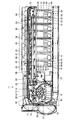
- 1 to 11 show a first embodiment.
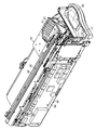
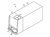
- FIG. 9 is a perspective view of the coin processing device 11.
- the coin processing device 11 is electrically connected to a POS register and can be used as an automatic change dispenser capable of automatically depositing and dispensing coins.
- the machine body 12 of the coin processing apparatus 11 includes a frame body 13 having an open front surface and a main unit 14 that can be pulled out from the front surface of the frame body 13.
- a coin insertion slot 15 for inserting coins is formed on the upper surface of the main unit 14.
- a coin outlet 16 On the right side of the front surface of the main unit 14 is formed a coin outlet 16 through which coins are paid out from the body 12, and on the left side of the front surface of the main unit 14 is formed a reject port 17 for returning unacceptable coins in the body 12. ing.
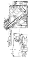
- the main unit 14 includes a feeding unit 21 that accepts coins (indicated by symbol C in the figure) inserted from the coin insertion slot 15 and feeds them one by one.
- a deposit transport unit 22 that transports the coins fed from the unit 21 from the front side to the rear side at the upper left side of the main unit 14, an identification unit 23 that identifies the coins transported by the deposit transport unit 22, and the identification unit
- a plurality of sorting sections 24 that sort coins transported by the deposit transport section 22 according to the identification result of 23, and are arranged in order from the front side to the rear side of the machine body 12, and are sorted by each sorting section 24.
- a plurality of stackers 26 each having a coin storage unit 25 for storing coins and allowing the stored coins to be discharged one by one in the right direction of the main unit 14, and a coin storage unit 25 disposed at the lower right side of the machine body 12.
- the coins discharged from the machine are transported to the front coin dispensing outlet 16 That and a dispensing and transporting unit 27.
- the feeding unit 21 stores coins in a non-aligned state between the rotating disk 30 that rotates about the rotation axis at a position inclined at a predetermined angle with respect to the horizontal direction and the surface side of the rotating disk 30.
- a hopper 31 and a delivery disk 32 for transferring coins one by one from the upper side of the rotating disk 30 to the deposit conveyance unit 22 are provided.
- the rotary disk 30 is inclined so that the left side is high and the right side is low when viewed from the front of the machine body 12, and the motor is rotated in the feeding rotation direction (counterclockwise direction in FIGS. 1 and 2) for feeding coins to the deposit conveyance unit 22. It rotates by driving.
- a plurality of pick-up members 33 protruding from the surface of the rotating disk 30 are arranged on the surface of the rotating disk 30 at a predetermined pitch along the circumferential direction.
- the pick-up member 33 is configured to hold the coins one by one and pick them up to the upper area of the rotating disk 30 when the rotating disk 30 rotates in the feeding rotation direction.
- the delivery disk 32 is configured to deliver the coins picked up by the pick-up member 33 to the upper area of the rotary disk 30 one by one to the deposit transport unit 22.
- the deposit conveyance section 22 includes a deposit conveyance path 36 formed from the front side to the rear side at the upper left side of the main unit 14.
- the deposit transfer passage 36 is flush with the surface of the rotating disk 30 and is disposed in an inclined state in which the left side is high and the right side is low, as viewed from the front of the machine body 12, similarly to the inclination of the rotating disk 30.
- a deposit conveyance belt 38 is disposed along the deposit conveyance path 36 by pulleys 37 disposed at the start and end portions of the deposit conveyance path 36.
- the deposit conveyance belt 38 rotates in the conveyance direction for conveying coins from the start end side to the end side of the deposit conveyance passage 36 by driving the pulley 37 with a motor.
- projections (not shown) for pushing and conveying coins one by one are projected at a predetermined pitch along the belt longitudinal direction.
- the rotation of the deposit conveyance belt 38 and the coin feeding by the rotary disk 30 and the delivery disk 32 of the feeding section 21 are linked, and one coin is fed from the feeding section 21 between adjacent protrusions of the deposit conveyance belt 38. It is configured to accept one by one.
- an identification unit 23 and a plurality of sorting units 24 are sequentially arranged along the conveyance direction from the front side to the rear side.
- the identification unit 23 detects the material, diameter, and the like of the coins that are transported through the deposit transport path 36, and identifies whether the coins are acceptable in the machine body 12, the acceptable coin denominations, and the like.
- the sorting unit 24 located at the most upstream sorting position in the transport direction of the deposit conveyance path 36 is a reject coin sorting unit 24 that sorts unacceptable coins into the machine body 12.
- the sorting sections 24 at a plurality of sorting positions on the downstream side of the transport are sorting sections 24 by type that sort coins that can be received in the machine body 12, and are all formed in the same structure.
- a sorting hole 41 capable of sorting coins is formed on the passage surface of the deposit conveyance path 36, and a gate 42 for opening and closing the sorting hole 41 is disposed.
- the gate 42 allows passage of coins to be transported in the deposit transport path 36 at the coin passing position where the sorting hole 41 is closed, and the gate 42 transports the deposit transport path 36 in the coin sorting position where the sorting hole 41 is opened. Sort coins into sorting hole 41.
- the gate 42 is forcibly switched between a coin passage position and a coin sorting position by an electric drive means 43 (see FIG. 10) such as a solenoid or a motor.
- the coins sorted by the reject coin sorting unit 24 are guided to the reject port 17 by a chute (not shown).
- the coins sorted by each sort unit 24 are stored in the respective coin storage units 25 arranged below the respective sort units 24.
- the stackers 26 are arranged side by side in the front-rear direction in a stacker storage section 46 formed in the lower region of the deposit conveyance section 22 of the main unit 14.
- the stacker storage portion 46 has an attachment / detachment opening 47 that opens on the left side, which is one side surface of the main unit 14, and each stacker 26 can be individually attached / detached through the attachment / detachment opening 47.
- each stacker 26 has a storage frame 50 in which two coin storage portions 25 are formed on the upper side, and one coin from each coin storage portion 25 is formed on the lower side.
- a discharge mechanism 51 that discharges each one is provided.
- a partition member 52 for partitioning the interior of the storage frame 50 into two is formed, and by this partition member 52, two coin storage portions 25 for storing coins in an unaligned state are formed. Yes.
- a receiving port 53 for receiving the coins selected by the respective selection units 24 of the deposit conveyance unit 22 located above is formed.
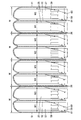
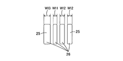
- each coin storage section 25 included in each stacker 26 is as follows: width W1 for small capacity (for small diameter and thin thickness), width W2 for medium capacity (for medium diameter and medium thickness), and large capacity (for large diameter and There are three types of width W3 (for large thickness), and there is a relationship of W1 ⁇ W2 ⁇ W3.
- the stacker 26 includes a small-capacity width W1 coin storage section 25 and a large-capacity width W3 coin storage section 25.
- the stackers 26 have different capacities of the two coin storage sections 25.
- the allocation of the coin storage unit 25 of each capacity may be determined in consideration of the diameter or thickness of the coin, or may be associated with the handling amount for each type of coin. For example, for large-sized coins, thick coins, or types of coins with a large amount of handling, a wide width W3 and a large-capacity coin storage unit 25 are allocated, and a small-diameter coin, a thin coin, or a small amount of handling For types of coins, the width W1 is narrow and a small-capacity coin storage unit 25 is allocated. For medium-sized coins, medium-thick coins, or types of coins with a large or small amount handled, A medium-capacity coin storage unit 25 having a width W2 is allocated.
- the stacker storage section 46 is provided with four stacker storage positions capable of storing four stackers 26, respectively.
- Each stacker 26 is detachably attached to each stacker storage position of the stacker storage unit 46 by the same mounting means.
- the attachment means is not shown, for example, rails are arranged in the stacker storage positions of the stacker storage portion 46 along the mounting / demounting direction of the stacker 26, and the stacker 26 is slidably engaged with the rails.
- the position of the stacker 26 in the front-rear direction of the stacker storage portion 46 is positioned, and the stacker 26 is slid along the rail.
- the stacker storage unit 46 is detachable.
- the relationship between the rail and the groove may be reversed, and the mounting structure is not limited to the rail and the groove, and other structures may be used.
- the attachment means makes it possible to select each of the sorting units 24 of the deposit transport unit 22 and each of the stackers 26 above the stacker storage unit 46.
- the position of the receiving port 53 of the coin storage unit 25 coincides, and the coins selected by each selection unit 24 can be received in each coin storage unit 25.
- the discharge mechanism 51 of the stacker 26 includes a discharge belt 57 disposed at the bottom of the coin storage portion 25 of the storage frame 50, and supports the coins in the coin storage portion 25 on the upper surface of the discharge belt 57.
- the coins in the coin storage unit 25 are discharged to the dispensing transport unit 27 by the rotation of 57.
- a coin discharge port 58 for discharging coins in the coin storage unit 25 by a discharge belt 57 is formed on the right side surface of the discharge mechanism 51 facing the dispensing transport unit 27.
- a reverse roller 59 that rotates in a direction opposite to the conveying direction of the discharge belt 57 and restricts the coins discharged by the discharge belt 57 one by one is arranged. It is installed.
- a stopper mechanism 60 that can control the coin discharge, a sensor 61 that counts the number of coins discharged from the coin discharge port 58, and the like are disposed at a position closer to the coin discharge port 58 than the reverse rotation roller 59. Has been.
- the withdrawal conveyance unit 27 includes a withdrawal conveyance belt (not shown) arranged along the front-rear direction of the main unit 14 and dispenses coins discharged from the coin discharge ports 58 of the plurality of coin storage units 25. It is placed on the gold transport belt and transported to the front coin payout exit 16.
- a plate 65 to which a substrate 64 as a component is attached is disposed on the left side surface of the main unit 14.
- the plate 65 is rotatably attached to the main unit 14 with the upper portion as a fulcrum.
- FIG. 6 in the state where the plate 65 is disposed along the left side surface of the main unit 14, the plate 65 and the plate 65
- the substrate 64 and the plate 65 are removed from the attachment / detachment port 47 of the stacker storage unit 46 by opening the plate 65 by rotating it upward as shown in FIGS.
- the stacker 26 can be removed and retracted.
- the substrate 64 and the main unit 14 side are connected by a flexible substrate or the like.
- FIG. 10 shows a block diagram of the coin processing device 11, and 71 is a control unit for controlling the entire coin processing device 11.
- the control unit 71 is provided on the substrate 64.
- Signals are input to the control unit 71 from the identification unit 23, a sensor group 72 including various sensors that detect coins at each position in the coin processing device 11, and the like.
- the control unit 71 controls the feeding unit 21, the deposit transport unit 22, each sorting unit 24, the stacker discharge mechanism 51, the stopper mechanism 60, the withdrawal transport unit 27, and the like.
- the control unit 71 includes storage means 73 for storing the correspondence between each sorting unit 24 and the coin sorting type, and based on the correspondence between each sorting unit 24 and the coin sorting type stored in the storage unit 73.
- the sorting unit 24 has a function of sorting coins transported by the deposit transport unit 22 in accordance with the identification result in the identifying unit 23.
- control unit 71 includes setting means 74 for setting the correspondence between each sorting unit 24 and the coin sorting type.
- the coin sorting type may be individually set for each sorting unit 24, or the number of corresponding relationships between each sorting unit 24 and the coin sorting type is stored in the storing means 73 in advance. If registered, the pattern may be selected and set. In this case, the correspondence between the plurality of sorting units 24 and the coin sorting types can be easily set.
- information of the type stored in the coin storage unit 25 of the stacker 26 is given by, for example, an IC tag, and the information of the type stored in the coin storage unit 25 of the stacker 26 on the main unit 14 side storing the stacker 26 is provided. And the correspondence between each sorting unit 24 and the coin sorting type may be automatically set.
- Coins inserted into the coin insertion slot 15 are received by the feeding unit 21.
- the rotating disk 30 and the delivery disk 32 are rotated by the start of the depositing operation, the coins are picked up one by one by the pick-up member 33 protruding from the surface of the rotating disk 30, and the deposit transport section 22 is picked up by the delivery disk 32.
- the deposit transport section 22 is picked up by the delivery disk 32.
- the deposit transport belt 38 rotates, and the coins fed one by one from the feed unit 21 into the deposit transport path 36 are transported while being pressed by the protrusions of the deposit transport belt 38.
- the coins transported in the deposit transport path 36 are identified by the identification unit 23.
- the deposit conveyance path 36 in the reject coin sorting section 24 located at the most upstream in the conveyance direction of the deposit conveyance path 36. And return to the reject port 17.
- the coin is transported to the position of the corresponding type sorting unit 24 and stored in the deposit conveyance path 36. Sort into part 25.
- the coins selected by the type-specific selection unit 24 fall into the coin storage unit 25 from the receiving port 53 of the corresponding type of coin storage unit 25, and are stored on the discharge belt 57 or on already stored coins.
- the identification unit 23 does not identify the coins for a predetermined time, it is determined that the processing of the coins inserted into the coin insertion slot 15 has been completed, the driving of the feeding unit 21 and the deposit transport unit 22 is stopped, and the deposit End the operation.
- the discharge belt 57 is rotated and the reverse rotation roller 59 is reversely rotated, so that the non-alignment on the discharge belt 57 is performed.
- the coins in a state are discharged from the coin discharge port 58 one by one.
- the stopper mechanism 60 forcibly stops the coin ejection.
- the coins discharged from the coin discharge port 58 of the coin storage unit 25 are paid out to the coin payout outlet 16 by the dispensing transport unit 27.
- a stacker 26 having two coin storage units 25 having different capacities is used, but the coin storage unit 25 of the stacker 26 is sorted by a plurality of sorting units 24 using an electric drive means 43.
- the coin storage unit 25 can be set freely according to the diameter and thickness of the coin, or the amount handled for each type of coin, and each coin can be stored without increasing the size of the device.
- the capacity of the section 25 can be used appropriately and effectively.
- sorting unit 24 sorts coins using the electric driving means 43, the type of coins sorted by each sorting unit 24 can be freely set and changed.
- the transport distance when depositing and dispensing the coins can be shortened, and the processing time can be reduced. It can be shortened and the occurrence rate of conveyance abnormality can be reduced.
- the setting means 74 sets the correspondence between each sorting unit 24 and the coin sorting type, and changes the coin sorting type in each sorting unit 24 to be changed.
- the position of the stacker 26 is changed so that the stacker 26 is provided with a coin storage unit 25 having a corresponding capacity, or in some cases, the stacker 26 is replaced with another stacker 26.
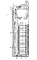
- the main unit 14 When replacing the stacker 26, first, the main unit 14 is pulled out from the frame 13. When the main unit 14 is pulled out, the depositing / conveying unit 22 is positioned above the stacker storage unit 46, and the withdrawal / conveying unit 27 is positioned on the right side of the stacker storage unit 46. As shown in FIG. The substrate 64 and the plate 65 are located so as to cover the left side of 46, that is, the attachment / detachment port 47. As shown in FIGS. 7 and 8, the substrate 64 and the plate 65 are pivoted upward and removed without removing the depositing / conveying unit 22 and the withdrawal / conveying unit 27, so that the attachment / detachment port 47 of the stacker storage unit 46 is opened. By exposing, the stacker 26 to be replaced is individually pulled out from the stacker storage position of the stacker storage unit 46, and the stacker 26 to be replaced with the stacker storage position of the empty stacker storage unit 46 is inserted and stored.
- all the stackers 26 have the same width and can be individually attached to and detached from the stacker storage portion 46, so that only the stacker 26 necessary for the change can be attached and detached without changing the stacker 26 that does not need to be changed. It is good and workability is good.
- each stacker 26 is detachably attached to each stacker storage position of the stacker storage section 46 by the same attachment means.
- a rail is disposed along the direction in which the stacker 26 is attached and detached, and the stacker 26 is formed with a groove portion slidably engaged with the rail. Therefore, even when each stacker 26 is stored in any of the stacker storage positions of the stacker storage unit 46, each of the sorting units 24 and each stacker 26 of the deposit transport unit 22 positioned above the stacker storage unit 46 is attached by the attaching means.
- the position of the receiving port 53 of the coin storage unit 25 coincides, and the coins selected by each selection unit 24 can be received in each coin storage unit 25.
- the setting means 74 sets the correspondence between each sorting unit 24 and the coin sorting type, and by changing the position of the stacker 26, the coins stored in the coin storage unit 25 of the stacker 26 are taken out.
- the positional relationship between the sorting unit 24 and the stacker 26 and the coin sorting type can be easily changed.
- the substrate 64 is disposed on the side of the attachment / detachment port 47 of the stacker storage section 46 for attaching / detaching the stacker 26, so that the limited space in the machine body 12 can be used effectively.
- the stacker 26 is attached / detached, the substrate 64 is rotated together with the plate 65 and retracted, and the stacker 26 can be attached / detached to / from the stacker storage portion 46.
- the configuration for retracting the substrate 64 is not limited to the rotation of the plate 65, and the plate 65 may be slid with respect to the main unit 14 or the plate 65 may be removed from the main unit 14.
- the substrate 64 may be arranged on the upper surface side of the main unit 14 and nothing may be arranged on the side of the attachment / detachment port 47 of the stacker storage unit 46.
- the number of coin storage units 25 of the stacker 26 is not limited to two.
- the number of coin storage units 25 having a horizontal width for small capacity is three, or one coin storage unit 25 having a medium width and two small coin storage units 25 are used. It is only necessary that the correspondence between each sorting unit 24 of the deposit transport unit 22 and the coin storage unit 25 is taken, for example, a total of three with the horizontal coin storage unit 25 for capacity.
- stacker 26 since it is easy to attach and detach and move, operation using the stacker 26 becomes possible. For example, at the end of the day's work, you can exchange it with a stacker 26 that contains the necessary denominations and amounts (for example, change reserves) the next day, or replace it with an empty stacker 26, Operation such as collection is easy.
- the cover can be opened and closed so that no coins can be taken out of the removed stacker 26, and a key that locks the cover with the cover closed is attached to the removed stacker 26. It is possible to easily realize an operation in which the person in charge of the transfer is handed over to the person in charge of the company and transferred to the bank.
- stacker 26 provided with two coin storage units 25 is used, as shown in the second embodiment of FIG. 11, the stacker 26 provided with one coin storage unit 25 is used. Also good.
- stackers 26 There are different types of stackers 26 with different capacities. That is, the stacker 26 is provided with a coin storage unit 25 in the lateral width W11 for small capacity (for small diameter and thin thickness), and the coin storage unit 25 is provided in the lateral width W12 for medium capacity (for medium diameter and medium thickness). There are three types of stackers 26, a stacker 26 in which a coin storage section 25 is provided in a lateral width W13 for large capacity (for large diameter and large thickness), and there is a relationship of W11 ⁇ W12 ⁇ W13.
- a coin storage unit 25 having a corresponding capacity can be set, and the capacity of each coin storage unit 25 can be appropriately and effectively used without increasing the size of the apparatus.
- the setting means 74 sets the correspondence between each sorting unit 24 and the coin sorting type, and the coin sorting by each sorting unit 24 to be changed.
- the position of the stacker 26 is changed so as to be replaced with the stacker 26 having the coin storage unit 25 having a capacity corresponding to the type.
- the stacker 26 can be individually attached to and detached from the stacker storage section 46, there is a case where only the stacker 26 necessary for the change may be attached and detached without changing the stacker 26 that does not need to be changed. Good sex. Moreover, when changing the position of the stacker 26, it is not necessary to take out the coins in the coin storage part 25 of the stacker 26, and the stacker 26 can be moved while the coins are stored in the coin storage part 25. Workability is good.
- the width varies depending on the type of the stacker 26, when the stackers 26 are stored in any position of the stacker storage unit 46, the sorting units 24 of the deposit transport unit 22 positioned above the stacker storage unit 46 If the positional relationship is set such that the coin storage unit 25 of each stacker 26 is positioned below, the coins selected by each selection unit 24 can be received in the coin storage unit 25 of each stacker 26.
- the stacker 26 is not limited to a mode in which the main unit 14 is pulled out of the frame 13 and the stacker 26 is attached or detached, and a door is provided on the left side surface of the frame 13 so that the door can be opened and closed.
- the stacker 26 may be attached or detached, or an opening for exposing the stacker 26 may be provided on the left side surface of the frame 13, and the stacker 26 may be attached or detached directly from the opening.
- the stacker 26 is not limited to being attached to and detached from the left side surface of the main unit 14, and depending on the mechanism of the main unit 14, for example, the stacker 26 may be attached or detached from the upper surface or the rear surface of the main unit 14.
- the stacker 26 is not limited to the aspect in which the coin storage part 25 and the discharge mechanism 51 are provided integrally, but may include only the coin storage part 25, and the discharge mechanism 51 may be provided on the main unit 14 side.
- each coin storage unit 25 may be color-coded so that the type can be identified.
- all the coin storage units 25 may be color-coded, or may be color-coded for small, medium, and large capacities. Management can be facilitated by associating the color and type of each coin storage unit 25 with each other.
- such a configuration of the stacker 26 is not limited to a coin processing machine having a depositing / withdrawing function, but can be applied to a depositing machine having only a depositing function or a dispensing machine having only a dispensing function.
- a dispensing machine in addition to the dispensing transport unit 27, as a replenishment function for selecting and replenishing replenishment coins by denomination to the coin storage unit 25 of each stacker 26, a deposit transport unit 22, An identification unit 23, a selection unit 24, and the like may be provided.
- the present invention is used for an automatic change dispenser connected to a POS register, a coin deposit / withdrawal machine for depositing / withdrawing coins, a coin deposit / dispensing machine for depositing coins, a coin dispenser for dispensing coins, and the like.
Landscapes
- Physics & Mathematics (AREA)
- General Physics & Mathematics (AREA)
- Testing Of Coins (AREA)
Abstract
Description
22 入金搬送部
23 識別部
24 選別部
25 硬貨収納部
26 スタッカ
27 出金搬送部
43 電気的駆動手段
46 スタッカ収納部
51 放出機構
53 受入口
71 制御部
73 記憶手段
74 設定手段
Claims (12)
- 硬貨処理装置において、
硬貨を搬送する入金搬送部と、
この入金搬送部によって搬送する硬貨を識別する識別部と、
前記入金搬送部に沿って設けられ、前記入金搬送部によって搬送する硬貨を前記識別部での識別結果に応じて選別する電気的駆動手段を有する複数の選別部と、
これら選別部に対応して選別部で選別された硬貨を収納する硬貨収納部を2つ以上有し、これら硬貨収納部の容量が異なる複数のスタッカと
を具備していることを特徴とする硬貨処理装置。 - 前記複数のスタッカを収納するスタッカ収納部を具備し、
前記複数のスタッカは、横幅が同一幅であり、前記スタッカ収納部に対して個別に着脱可能とする
ことを特徴とする請求項1記載の硬貨処理装置。 - 前記スタッカを前記スタッカ収納部に着脱可能とするとともに、前記スタッカの装着状態で前記各硬貨収納部の硬貨を受け入れる受入口を前記各選別部に対応して位置決めする取付手段を具備している
ことを特徴とする請求項2記載の硬貨処理装置。 - 前記各選別部と硬貨選別種類との対応関係を設定する設定手段と、
この設定手段で設定された前記各選別部と硬貨選別種類との対応関係を記憶する記憶手段と、
この記憶手段に記憶された前記各選別部と硬貨選別種類との対応関係に基づき、前記入金搬送部によって搬送する硬貨を前記識別部での識別結果に応じて前記選別部で選別させる制御部とを具備している
ことを特徴とする請求項2記載の硬貨処理装置。 - 硬貨処理装置において、
硬貨を収納する容量が異なる硬貨収納部を2つ以上有するとともに、各硬貨収納部毎に収納されている硬貨を放出可能とする放出機構を有する複数のスタッカと、
これらスタッカの硬貨収納部から放出される硬貨を受け入れて搬送する出金搬送部と
を具備していることを特徴とする硬貨処理装置。 - 前記複数のスタッカを収納するスタッカ収納部を具備し、
前記複数のスタッカは、横幅が同一幅であり、前記スタッカ収納部に対して個別に着脱可能とする
ことを特徴とする請求項5記載の硬貨処理装置。 - 硬貨を搬送する入金搬送部と、
この入金搬送部によって搬送する硬貨を識別する識別部と、
前記入金搬送部に沿って設けられ、前記入金搬送部によって搬送する硬貨を前記識別部での識別結果に応じて前記各スタッカの各硬貨収納部に対応して選別する電気的駆動手段を有する複数の選別部と、
前記入金搬送部に沿って設けられ、前記入金搬送部によって搬送する硬貨を前記識別部での識別結果に応じて選別する電気的駆動手段を有する複数の選別部と、
前記スタッカを前記スタッカ収納部に着脱可能とするとともに、前記スタッカの装着状態で前記各硬貨収納部の硬貨を受け入れる受入口を前記各選別部に対応して位置決めする取付手段を具備している
ことを特徴とする請求項6記載の硬貨処理装置。 - 前記各選別部と硬貨選別種類との対応関係を設定する設定手段と、
この設定手段で設定された前記各選別部と硬貨選別種類との対応関係を記憶する記憶手段と、
この記憶手段に記憶された前記各選別部と硬貨選別種類との対応関係に基づき、前記入金搬送部によって搬送する硬貨を前記識別部での識別結果に応じて前記選別部で選別させる制御部とを具備している
ことを特徴とする請求項7記載の硬貨処理装置。 - 硬貨処理装置において、
硬貨を搬送する入金搬送部と、
この入金搬送部によって搬送する硬貨を識別する識別部と、
前記入金搬送部に沿って設けられ、前記入金搬送部によって搬送する硬貨を前記識別部での識別結果に応じて選別する電気的駆動手段を有する複数の選別部と、
これら選別部に対応して選別部で選別された硬貨を収納する硬貨収納部を有し、この硬貨収納部の容量が異なる複数のスタッカと
を具備していることを特徴とする硬貨処理装置。 - 前記複数のスタッカを収納するスタッカ収納部を具備し、
前記複数のスタッカは、前記スタッカ収納部に対して個別に着脱可能とする
ことを特徴とする請求項9記載の硬貨処理装置。 - 前記スタッカを前記スタッカ収納部に着脱可能とするとともに、前記スタッカの装着状態で前記各硬貨収納部の硬貨を受け入れる受入口を前記各選別部に対応して位置決めする取付手段を具備している
ことを特徴とする請求項10記載の硬貨処理装置。 - 前記各選別部と硬貨選別種類との対応関係を設定する設定手段と、
この設定手段で設定された前記各選別部と硬貨選別種類との対応関係を記憶する記憶手段と、
この記憶手段に記憶された前記各選別部と硬貨選別種類との対応関係に基づき、前記入金搬送部によって搬送する硬貨を前記識別部での識別結果に応じて前記選別部で選別させる制御部とを具備している
ことを特徴とする請求項10記載の硬貨処理装置。
Priority Applications (4)
| Application Number | Priority Date | Filing Date | Title |
|---|---|---|---|
| JP2009551338A JPWO2009095987A1 (ja) | 2008-01-29 | 2008-01-29 | 硬貨処理装置 |
| EP08704048A EP2249317A4 (en) | 2008-01-29 | 2008-01-29 | APPARATUS FOR HANDLING COINS OF CURRENCY |
| US12/735,555 US8498736B2 (en) | 2008-01-29 | 2008-01-29 | Coin handling machine |
| PCT/JP2008/051239 WO2009095987A1 (ja) | 2008-01-29 | 2008-01-29 | 硬貨処理装置 |
Applications Claiming Priority (1)
| Application Number | Priority Date | Filing Date | Title |
|---|---|---|---|
| PCT/JP2008/051239 WO2009095987A1 (ja) | 2008-01-29 | 2008-01-29 | 硬貨処理装置 |
Publications (1)
| Publication Number | Publication Date |
|---|---|
| WO2009095987A1 true WO2009095987A1 (ja) | 2009-08-06 |
Family
ID=40912357
Family Applications (1)
| Application Number | Title | Priority Date | Filing Date |
|---|---|---|---|
| PCT/JP2008/051239 Ceased WO2009095987A1 (ja) | 2008-01-29 | 2008-01-29 | 硬貨処理装置 |
Country Status (4)
| Country | Link |
|---|---|
| US (1) | US8498736B2 (ja) |
| EP (1) | EP2249317A4 (ja) |
| JP (1) | JPWO2009095987A1 (ja) |
| WO (1) | WO2009095987A1 (ja) |
Families Citing this family (7)
| Publication number | Priority date | Publication date | Assignee | Title |
|---|---|---|---|---|
| JP5775776B2 (ja) * | 2011-09-28 | 2015-09-09 | グローリー株式会社 | 硬貨繰出装置、硬貨入出金機および硬貨繰出方法 |
| US10282931B2 (en) * | 2011-02-22 | 2019-05-07 | Glory Ltd. | Coin depositing and dispensing machine |
| DE102011001870A1 (de) * | 2011-04-07 | 2012-10-11 | Wincor Nixdorf International Gmbh | Vorrichtung und Verfahren zum Sortieren von Münzen |
| JP5953829B2 (ja) * | 2012-03-02 | 2016-07-20 | 富士電機株式会社 | 硬貨収納装置 |
| JP2014010680A (ja) * | 2012-06-29 | 2014-01-20 | Glory Ltd | 硬貨払出装置およびドロア |
| JP7256037B2 (ja) * | 2019-03-05 | 2023-04-11 | グローリー株式会社 | 硬貨処理装置及び硬貨処理方法 |
| WO2022021331A1 (zh) * | 2020-07-31 | 2022-02-03 | 齐心商用设备(深圳)有限公司 | 一种点钞机 |
Citations (4)
| Publication number | Priority date | Publication date | Assignee | Title |
|---|---|---|---|---|
| JP2003030710A (ja) * | 2001-07-13 | 2003-01-31 | Glory Ltd | 硬貨入金装置 |
| JP2004265066A (ja) * | 2003-02-28 | 2004-09-24 | Oki Electric Ind Co Ltd | 硬貨管理装置 |
| JP2005202491A (ja) * | 2004-01-13 | 2005-07-28 | Laurel Seiki Kk | 貨幣入出金機 |
| JP2007279907A (ja) | 2006-04-04 | 2007-10-25 | Glory Ltd | 硬貨入出金機 |
Family Cites Families (9)
| Publication number | Priority date | Publication date | Assignee | Title |
|---|---|---|---|---|
| JPS57274U (ja) * | 1980-05-30 | 1982-01-05 | ||
| GB2246897B (en) * | 1990-08-10 | 1994-04-13 | Mars Inc | Coin testing mechanism |
| JP2976159B2 (ja) * | 1992-08-31 | 1999-11-10 | 富士電機株式会社 | 硬貨入出金装置 |
| GB2332552B (en) * | 1997-12-18 | 2002-01-30 | Mars Inc | Coin mechanism |
| US6637576B1 (en) * | 1999-04-28 | 2003-10-28 | Cummins-Allison Corp. | Currency processing machine with multiple internal coin receptacles |
| EP1321905A4 (en) * | 2000-09-18 | 2007-07-25 | Glory Kogyo Kk | MONITOR OF COINS AND DEVICE FOR INTRODUCING PARTS |
| JP2004272461A (ja) * | 2003-03-06 | 2004-09-30 | Oki Electric Ind Co Ltd | 硬貨処理装置 |
| US7992699B2 (en) * | 2003-04-10 | 2011-08-09 | Talaris Inc. | Machine and method for cash recycling and cash settlement |
| JP4665087B2 (ja) * | 2005-01-05 | 2011-04-06 | 旭精工株式会社 | 硬貨入出金装置 |
-
2008
- 2008-01-29 US US12/735,555 patent/US8498736B2/en not_active Expired - Fee Related
- 2008-01-29 WO PCT/JP2008/051239 patent/WO2009095987A1/ja not_active Ceased
- 2008-01-29 JP JP2009551338A patent/JPWO2009095987A1/ja not_active Ceased
- 2008-01-29 EP EP08704048A patent/EP2249317A4/en not_active Withdrawn
Patent Citations (4)
| Publication number | Priority date | Publication date | Assignee | Title |
|---|---|---|---|---|
| JP2003030710A (ja) * | 2001-07-13 | 2003-01-31 | Glory Ltd | 硬貨入金装置 |
| JP2004265066A (ja) * | 2003-02-28 | 2004-09-24 | Oki Electric Ind Co Ltd | 硬貨管理装置 |
| JP2005202491A (ja) * | 2004-01-13 | 2005-07-28 | Laurel Seiki Kk | 貨幣入出金機 |
| JP2007279907A (ja) | 2006-04-04 | 2007-10-25 | Glory Ltd | 硬貨入出金機 |
Non-Patent Citations (1)
| Title |
|---|
| See also references of EP2249317A4 * |
Also Published As
| Publication number | Publication date |
|---|---|
| US20100312378A1 (en) | 2010-12-09 |
| JPWO2009095987A1 (ja) | 2011-05-26 |
| EP2249317A1 (en) | 2010-11-10 |
| US8498736B2 (en) | 2013-07-30 |
| EP2249317A4 (en) | 2012-12-12 |
Similar Documents
| Publication | Publication Date | Title |
|---|---|---|
| JP5274549B2 (ja) | 硬貨処理装置 | |
| KR100492203B1 (ko) | 지폐 입출금 장치 | |
| JPWO2008099477A1 (ja) | 硬貨入出金機 | |
| CN102254362B (zh) | 纸页类管理装置以及纸页类管理方法 | |
| JPWO2009095987A1 (ja) | 硬貨処理装置 | |
| KR20060046084A (ko) | 지폐입출금기 | |
| JP4336519B2 (ja) | 循環式硬貨入出金機 | |
| WO2008032350A1 (en) | Coin receiving and ejecting device | |
| JP4772547B2 (ja) | 卓上型硬貨入出金機 | |
| CN107408321B (zh) | 纸币处理装置以及纸币的精查处理方法 | |
| JP5352344B2 (ja) | 硬貨処理機 | |
| JP3499702B2 (ja) | 硬貨入出金機 | |
| JP3015161B2 (ja) | 循環式紙幣入出金装置 | |
| JP2004334597A (ja) | 循環式硬貨入出金機 | |
| JP2004326541A (ja) | 循環式硬貨入出金機の精査処理装置 | |
| JP2003030713A (ja) | 硬貨入出金機 | |
| JP2935452B2 (ja) | 循環式硬貨入出金機 | |
| WO2009125482A1 (ja) | 硬貨処理装置 | |
| JP2710597B2 (ja) | 循環式硬貨入出金機の硬貨回収装置 | |
| JP3929726B2 (ja) | 紙幣入出金機 | |
| JP3214841B2 (ja) | 循環式硬貨入出金機 | |
| JP3779821B2 (ja) | 硬貨処理機 | |
| JP3850304B2 (ja) | 紙幣入出金機 | |
| JP3844697B2 (ja) | 紙幣入出金機 | |
| JP2004326542A (ja) | 循環式硬貨入出金機の回収処理装置 |
Legal Events
| Date | Code | Title | Description |
|---|---|---|---|
| 121 | Ep: the epo has been informed by wipo that ep was designated in this application |
Ref document number: 08704048 Country of ref document: EP Kind code of ref document: A1 |
|
| ENP | Entry into the national phase |
Ref document number: 2009551338 Country of ref document: JP Kind code of ref document: A |
|
| WWE | Wipo information: entry into national phase |
Ref document number: 12735555 Country of ref document: US |
|
| WWE | Wipo information: entry into national phase |
Ref document number: 2008704048 Country of ref document: EP |
|
| NENP | Non-entry into the national phase |
Ref country code: DE |