WO2009096143A1 - 摺動部材、及び、摺動部材の表面処理方法 - Google Patents
摺動部材、及び、摺動部材の表面処理方法 Download PDFInfo
- Publication number
- WO2009096143A1 WO2009096143A1 PCT/JP2009/000123 JP2009000123W WO2009096143A1 WO 2009096143 A1 WO2009096143 A1 WO 2009096143A1 JP 2009000123 W JP2009000123 W JP 2009000123W WO 2009096143 A1 WO2009096143 A1 WO 2009096143A1
- Authority
- WO
- WIPO (PCT)
- Prior art keywords
- hard particles
- sliding member
- top surface
- valve
- particles
- Prior art date
- Legal status (The legal status is an assumption and is not a legal conclusion. Google has not performed a legal analysis and makes no representation as to the accuracy of the status listed.)
- Ceased
Links
Images

Classifications
-
- F—MECHANICAL ENGINEERING; LIGHTING; HEATING; WEAPONS; BLASTING
- F01—MACHINES OR ENGINES IN GENERAL; ENGINE PLANTS IN GENERAL; STEAM ENGINES
- F01L—CYCLICALLY OPERATING VALVES FOR MACHINES OR ENGINES
- F01L1/00—Valve-gear or valve arrangements, e.g. lift-valve gear
- F01L1/02—Valve drive
- F01L1/04—Valve drive by means of cams, camshafts, cam discs, eccentrics or the like
- F01L1/047—Camshafts
- F01L1/053—Camshafts overhead type
-
- C—CHEMISTRY; METALLURGY
- C23—COATING METALLIC MATERIAL; COATING MATERIAL WITH METALLIC MATERIAL; CHEMICAL SURFACE TREATMENT; DIFFUSION TREATMENT OF METALLIC MATERIAL; COATING BY VACUUM EVAPORATION, BY SPUTTERING, BY ION IMPLANTATION OR BY CHEMICAL VAPOUR DEPOSITION, IN GENERAL; INHIBITING CORROSION OF METALLIC MATERIAL OR INCRUSTATION IN GENERAL
- C23C—COATING METALLIC MATERIAL; COATING MATERIAL WITH METALLIC MATERIAL; SURFACE TREATMENT OF METALLIC MATERIAL BY DIFFUSION INTO THE SURFACE, BY CHEMICAL CONVERSION OR SUBSTITUTION; COATING BY VACUUM EVAPORATION, BY SPUTTERING, BY ION IMPLANTATION OR BY CHEMICAL VAPOUR DEPOSITION, IN GENERAL
- C23C8/00—Solid state diffusion of only non-metal elements into metallic material surfaces; Chemical surface treatment of metallic material by reaction of the surface with a reactive gas, leaving reaction products of surface material in the coating, e.g. conversion coatings, passivation of metals
- C23C8/02—Pretreatment of the material to be coated
-
- C—CHEMISTRY; METALLURGY
- C23—COATING METALLIC MATERIAL; COATING MATERIAL WITH METALLIC MATERIAL; CHEMICAL SURFACE TREATMENT; DIFFUSION TREATMENT OF METALLIC MATERIAL; COATING BY VACUUM EVAPORATION, BY SPUTTERING, BY ION IMPLANTATION OR BY CHEMICAL VAPOUR DEPOSITION, IN GENERAL; INHIBITING CORROSION OF METALLIC MATERIAL OR INCRUSTATION IN GENERAL
- C23C—COATING METALLIC MATERIAL; COATING MATERIAL WITH METALLIC MATERIAL; SURFACE TREATMENT OF METALLIC MATERIAL BY DIFFUSION INTO THE SURFACE, BY CHEMICAL CONVERSION OR SUBSTITUTION; COATING BY VACUUM EVAPORATION, BY SPUTTERING, BY ION IMPLANTATION OR BY CHEMICAL VAPOUR DEPOSITION, IN GENERAL
- C23C8/00—Solid state diffusion of only non-metal elements into metallic material surfaces; Chemical surface treatment of metallic material by reaction of the surface with a reactive gas, leaving reaction products of surface material in the coating, e.g. conversion coatings, passivation of metals
- C23C8/06—Solid state diffusion of only non-metal elements into metallic material surfaces; Chemical surface treatment of metallic material by reaction of the surface with a reactive gas, leaving reaction products of surface material in the coating, e.g. conversion coatings, passivation of metals using gases
- C23C8/08—Solid state diffusion of only non-metal elements into metallic material surfaces; Chemical surface treatment of metallic material by reaction of the surface with a reactive gas, leaving reaction products of surface material in the coating, e.g. conversion coatings, passivation of metals using gases only one element being applied
- C23C8/24—Nitriding
- C23C8/26—Nitriding of ferrous surfaces
-
- F—MECHANICAL ENGINEERING; LIGHTING; HEATING; WEAPONS; BLASTING
- F01—MACHINES OR ENGINES IN GENERAL; ENGINE PLANTS IN GENERAL; STEAM ENGINES
- F01L—CYCLICALLY OPERATING VALVES FOR MACHINES OR ENGINES
- F01L1/00—Valve-gear or valve arrangements, e.g. lift-valve gear
- F01L1/12—Transmitting gear between valve drive and valve
- F01L1/14—Tappets; Push rods
- F01L1/143—Tappets; Push rods for use with overhead camshafts
-
- F—MECHANICAL ENGINEERING; LIGHTING; HEATING; WEAPONS; BLASTING
- F01—MACHINES OR ENGINES IN GENERAL; ENGINE PLANTS IN GENERAL; STEAM ENGINES
- F01L—CYCLICALLY OPERATING VALVES FOR MACHINES OR ENGINES
- F01L1/00—Valve-gear or valve arrangements, e.g. lift-valve gear
- F01L1/12—Transmitting gear between valve drive and valve
- F01L1/18—Rocking arms or levers
- F01L1/181—Centre pivot rocking arms
-
- F—MECHANICAL ENGINEERING; LIGHTING; HEATING; WEAPONS; BLASTING
- F16—ENGINEERING ELEMENTS AND UNITS; GENERAL MEASURES FOR PRODUCING AND MAINTAINING EFFECTIVE FUNCTIONING OF MACHINES OR INSTALLATIONS; THERMAL INSULATION IN GENERAL
- F16H—GEARING
- F16H53/00—Cams or cam-followers, e.g. rollers for gearing mechanisms
- F16H53/06—Cam-followers
-
- F—MECHANICAL ENGINEERING; LIGHTING; HEATING; WEAPONS; BLASTING
- F01—MACHINES OR ENGINES IN GENERAL; ENGINE PLANTS IN GENERAL; STEAM ENGINES
- F01L—CYCLICALLY OPERATING VALVES FOR MACHINES OR ENGINES
- F01L1/00—Valve-gear or valve arrangements, e.g. lift-valve gear
- F01L1/12—Transmitting gear between valve drive and valve
- F01L1/14—Tappets; Push rods
- F01L1/16—Silencing impact; Reducing wear
-
- F—MECHANICAL ENGINEERING; LIGHTING; HEATING; WEAPONS; BLASTING
- F01—MACHINES OR ENGINES IN GENERAL; ENGINE PLANTS IN GENERAL; STEAM ENGINES
- F01L—CYCLICALLY OPERATING VALVES FOR MACHINES OR ENGINES
- F01L2301/00—Using particular materials
Definitions
- the present invention relates to a sliding member used in an internal combustion engine, and a surface treatment method of the sliding member.
- an object of the present invention is to improve the wear resistance of a sliding member used in an internal combustion engine or the like for achieving high output and high rotation.
- the sliding member of the present invention is a sliding member used in an internal combustion engine, in which hard particles having a hardness higher than that of the sliding member are dispersed on the surface of the sliding member.
- the surface on which the particles are dispersed is subjected to a nitriding treatment.
- a nitrided layer containing the hard particles is formed on this surface.
- This nitrided layer is increased in wear resistance by nitriding the base material of the sliding member, and is further increased in wear resistance by the inclusion of hard particles. Therefore, a nitride layer having high wear resistance can be formed on the sliding member, and the wear resistance of the sliding member can be improved.
- the hard particles may be particles of aluminum oxide.
- the hard particles of aluminum oxide dispersed on the surface of the sliding member are compatible with the nitriding treatment, the hard particles are easily contained in the nitrided layer formed by the nitriding treatment. Therefore, it is possible to easily form a nitride layer containing hard particles and having increased wear resistance on the surface of the sliding member, and to improve the wear resistance of the sliding member.
- the particles of aluminum oxide are high in hardness and low in cost, there is an advantage that the wear resistance can be enhanced at low cost.
- the hard particles may be particles having a particle size of 10 ⁇ m (micrometer) or less.
- the particle diameter of the hard particles contained in the nitride layer is small, the unevenness on the surface of the nitride layer can be suppressed, and the friction loss on the surface subjected to the nitriding treatment can be reduced.
- the hard particles may be dispersed on the surface so that the hard particles occupy at least 5% as a concentration of the surface, and may be subjected to a nitriding treatment. In this case, since the nitrided layer can contain a sufficient amount of hard particles, the wear resistance of the nitrided layer can be enhanced.
- the sliding surface with the other member of the sliding member may be polished by the hard particles and further subjected to a nitriding treatment.
- polishing with hard particles when the hard particles collide with or slide into the sliding surface of the sliding member, a recess is formed in the sliding surface, and this recess is an oil when assembled to an internal combustion engine Act as a pit.
- the sliding member may be a valve lifter that opens and closes an engine valve by sliding with another member in the internal combustion engine.
- the wear resistance of the valve lifter is formed by forming a nitride layer excellent in wear resistance on the surface of the valve lifter to which a high load has been applied in an internal combustion engine in which further high power and high rotation have been achieved in recent years. Can be improved.
- the surface treatment method of a sliding member is the surface treatment method of a sliding member used in an internal combustion engine, wherein the surface of the sliding member is harder than the sliding member. It is characterized by including a step of dispersing hard particles, and a step of nitriding the surface on which the hard particles are dispersed.
- the surface on which the hard particles are dispersed is nitrided to form a nitride layer containing the hard particles on the surface.
- This nitrided layer is increased in wear resistance by nitriding the base material of the sliding member, and is further increased in wear resistance by containing hard particles. Therefore, a nitride layer having high wear resistance can be formed on the sliding member, and the wear resistance of the sliding member can be improved.
- the sliding member is a valve lifter that opens and closes an engine valve by sliding with another member in the internal combustion engine
- the step of dispersing the hard particles on the surface of the sliding member is the hard particle And polishing the sliding surface that slides with the other member.
- the sliding surface is polished by the hard particles, so smoothing of the surface roughness of the sliding surface is achieved, and friction on this sliding surface is achieved. The loss can be reduced and the hard particles can be efficiently dispersed on the sliding surface.
- the surface on which the hard particles are dispersed is nitrided to form a highly wear-resistant nitrided layer containing the hard particles on the surface of the sliding member, and the wear resistance of the sliding member Can be improved.
- the hard particles are easily included in the nitrided layer formed by the nitriding treatment, and the nitrided layer containing the hard particles is easily slid It can be generated on the surface of the member.
- the wear resistance of the surface of the sliding member can be enhanced while suppressing the cost increase.
- the hard particles into particles with a particle diameter of 10 ⁇ m or less, it is possible to suppress the unevenness of the nitrided layer and to reduce the friction loss of the surface subjected to the nitriding treatment. Also, by dispersing hard particles on the surface of the sliding member so that the surface concentration is at least 5%, a sufficient amount of hard particles can be contained in the nitride layer, and the wear resistance of the nitride layer Can be enhanced.
- the sliding surface of the sliding member and other members is polished with hard particles and further subjected to a nitriding treatment to smooth the surface roughness of the sliding surface and reduce the friction loss on this sliding surface. It can be done.
- a nitriding treatment to smooth the surface roughness of the sliding surface and reduce the friction loss on this sliding surface. It can be done.
- the number of processing steps can be reduced.
- the sliding member is a valve lifter that opens and closes the engine valve by sliding with other members in the internal combustion engine, a high load is applied to the internal combustion engine that has recently achieved higher output and higher rotation.
- the wear resistance of the valve lifter can be improved by forming a nitride layer excellent in wear resistance on the surface of the valve lifter.
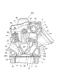
- FIG. 1 is a cross-sectional view showing an example of an internal combustion engine according to the present invention.
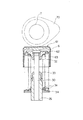
- FIG. 2 is a cross-sectional view of the main parts showing the structure of the valve lifter and the vicinity thereof.
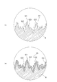
- FIG. 3 is a view schematically showing an example of the surface condition of the valve lifter according to the first embodiment, FIG. 3A is an enlarged view showing the surface condition before the polishing process, and FIG. 3B shows the surface condition in the polishing process It is an enlarged view.
- FIG. 4 is a view schematically showing an example of the surface state of the valve lifter according to the first embodiment, FIG. 4A is an enlarged view showing the surface state after the polishing step, and FIG. 4B is the surface state after the nitriding treatment It is an enlarged view shown typically.
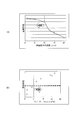
- FIG. 5 is a chart showing the wear resistance obtained by the surface treatment of the first embodiment
- FIG. 5A shows the correlation between the particle size and the wear resistance
- FIG. 5B shows the concentration of hard particles and the wear resistance
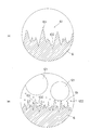
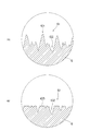
- FIG. 6 is a view schematically showing the surface condition of the valve lifter according to the second embodiment
- FIG. 6A is an enlarged view showing the surface condition before nitriding treatment
- FIG. 6B is an enlargement showing the surface condition after nitriding treatment
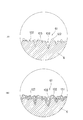
- FIG. 7 is a view schematically showing the surface state of the valve lifter according to the third embodiment
- FIG. 7A is an enlarged view showing the surface state before the polishing step
- FIG. 7B is an enlarged view showing the surface state after the polishing step
- FIG. 8 is a view schematically showing the surface condition of the valve lifter according to the third embodiment
- FIG. 8A is an enlarged view showing the surface condition before nitriding treatment
- FIG. 8B is an enlargement showing the surface condition after nitriding treatment
- FIG. 1 is a cross-sectional view showing an example of an internal combustion engine 100 in the present embodiment.
- An internal combustion engine 100 in the present embodiment includes a cylinder block 1 and a cylinder head 2 attached to the cylinder block 1 via a head gasket 10.
- a cylinder 11 is formed in the cylinder block 1, a piston 12 slidably fitted in the cylinder 11 is disposed in the cylinder 11, and a crankshaft 12 rotatably supported on the cylinder block 1 (shown in FIG. The connection is made via a connecting rod (not shown). Further, the cylinder block 1 is formed with water jackets 13 and 14 for circulating cooling water for cooling the cylinder block 1 so as to surround the piston 12.
- a combustion chamber 20 is provided above the cylinder 11, and an intake port 21 and an exhaust port 22 communicating with the combustion chamber 20 are provided.
- the intake port 21 is an exhaust valve 22 by an intake valve 3.
- the valve 4 opens and closes as described later.
- internal combustion engine 100 a mixture of fuel and air taken in from intake port 21 is compressed in combustion chamber 20 formed between piston 12 and cylinder head 2 and ignited by an ignition plug not shown.
- the piston 12 is pressed downward by the combustion pressure, and the pressing force rotates the crankshaft.
- the exhaust port 22 opened by the exhaust valve 4 the piston 12 ascends by rotation of the crankshaft and compresses the combustion chamber 20 with the cylinder head 2 to burn the exhaust gas.
- Water jackets 23, 24, 25 for cooling the cylinder head 2 are formed on the cylinder head 2 so as to surround the intake port 21 and the exhaust port 22. These water jackets 23, 24, 25 are flow paths for flowing the cooling fluid into the cylinder head 2.
- An intake valve 3 (engine valve) for opening and closing the intake port 21 is disposed on the cylinder head 2 in a direction (valve closing direction) for closing the intake port 21 by the valve spring 3a.
- the exhaust valve 4 (engine valve) is disposed to be biased by a valve spring 4 a in a direction (valve closing direction) for closing the exhaust port 22.
- the intake valve 3 includes a round rod-like stem 30 and a substantially conical umbrella portion 31 integrally formed at the tip of the stem 30.
- the intake valve 3 is disposed through a stem 30 in a substantially cylindrical valve guide 26 fitted to the cylinder head 2 so as to protrude in the middle of the intake port 21, and is slidably supported by the valve guide 26.
- Ru A valve lifter 6 (sliding member) having a bottomed cylindrical shape is placed on the top of the stem 30 together with the upper portion of the valve spring 3 a and abuts on the camshaft 7 via the valve lifter 6.
- the exhaust valve 4 has a round bar-like stem 40 similar to the intake valve 3 and a substantially conical umbrella portion 41 integrally formed at the tip of the stem 40. This stem 40 is located in the middle of the exhaust port 22.
- a stem 40 is disposed through a substantially cylindrical valve guide 27 fitted to the cylinder head 2 so as to protrude therefrom, and is slidably supported by the valve guide 27.
- a valve spring 4 a is disposed on the stem 40, and an end of a rocker arm 80 described later abuts on the top of the stem 40.
- Annular valve seals 21 a and 22 a are disposed on the combustion chamber 20 side of the intake port 21 and the exhaust port 22, respectively.
- the outer peripheral edge of the umbrella portion 31 of the intake valve 3 and the valve seal 21a form a seal surface, whereby the intake port 21 is closed, and when the exhaust valve 4 is closed, the umbrella of the exhaust valve 4
- the exhaust port 22 is closed by the outer peripheral edge portion of 41 and the valve seal 22a forming a sealing surface.
- the internal combustion engine 100 is provided with a unicam type valve gear 5 driven by a single camshaft 7, and the valve gear 5 drives the intake valve 3 and the exhaust valve 4 to open and close.
- the valve gear 5 has a camshaft 7 rotatably supported by the cylinder head 2 above the intake valve 3 and a rocker shaft 8 fixed to the cylinder head 2 with an axis parallel to the camshaft 7. Have.
- the camshaft 7 is connected to the crankshaft by a chain transmission mechanism (not shown) and rotates in conjunction with the crankshaft.
- the camshaft 7 is provided with a substantially disk-like intake cam 70 and an exhaust cam 71, the circumferential surface of the intake cam 70 is in contact with the top surface 61 of the valve lifter 6, and the circumferential surface of the exhaust cam 71 is a rocker shaft 8 It is in contact with a rocker arm 80 rotatably disposed at the center.
- the intake valve 3 moves up and down through the valve lifter 6 according to the cross-sectional shape (profile) of the intake cam 70
- the exhaust valve 4 moves up and down through the rocker arm 80 according to the profile of the exhaust cam 71.
- the intake port 21 and the exhaust port 22 are opened at the timing of.
- the rocker arm 80 is rotatably supported by the rocker shaft 8 and provided at one end thereof with a roller 81 in rolling contact with the exhaust cam 71 and at the other end with a tappet screw 82 which abuts on the top of the stem 40 of the exhaust valve 4. Is listed as adjustable in position.
- the rocker arm 80 rotates about the rocker shaft 8 with the rotation of the exhaust cam 71 and presses the exhaust valve 4 via the tappet screw 82 to open and close the exhaust valve 4.
- a bottomed cylindrical valve lifter 6 is placed so that the bottom surface is on top, and the top of the stem 30 is in contact with the inside of the bottom of the valve lifter 6 via a shim 62. .
- the top surface 61 of the valve lifter 6 is in contact with the circumferential surface of the intake cam 70 as described above by the biasing force of the valve spring 3a, and the intake cam 70 resists the biasing force of the valve spring 3a as the camshaft 7 rotates. Then, when the valve lifter 6 is pressed, the intake valve 3 is depressed together with the valve lifter 6 and moves in the valve opening direction.
- the distance between the valve lifter 6 and the intake cam 70 can be adjusted by changing the thickness of the shim 62. Further, the edge of the top surface 61 is chamfered.
- the top surface 61 of the valve lifter 6 always slides on the circumferential surface of the intake cam 70.
- iron or the like excellent in contact pressure is used as the material of the top surface 61 of the valve lifter 6.
- the top surface 61 is subjected to a surface treatment to enhance wear resistance.
- the surface treatment of the top surface 61 will be described.
- FIGS. 3 and 4 are views schematically illustrating the surface condition of the valve lifter 6 according to the first embodiment, and FIG. 3A is an enlarged view showing the surface condition before the polishing step (first step described later).
- FIG. 3B is an enlarged view showing the surface state during the polishing step
- FIG. 4A is an enlarged view showing the surface state after the polishing step
- FIG. 4B is an enlarged view showing the surface state after nitriding treatment (second step described later) It is.
- FIGS. 3 to 4 and FIGS. 6 to 8 which will be described later are all diagrams showing the microstructure on the surface of the top surface 61 to a large scale, and are partially illustrated for the convenience of understanding. .
- the valve lifter 6 is cut out from an iron-based material formed into a substantially cylindrical shape by casting or forging or drawing, or from an iron-based material formed into a bottomed cup by casting or forging, and the stem 30 and the valve spring 3a. While the space for housing etc. is formed by turning, the top surface 61 is processed into a flat surface by grinding. As shown in FIG. 3A, although the top surface 61 after the grinding process is a smooth surface, the presence of the convex portion 101 and the concave portion 102 can be seen when it is greatly enlarged.
- the surface treatment of the top surface 61 in the first embodiment is performed in the following procedure.
- First step The top surface 61 is polished using hard particles.
- the first step polishing is performed to make the top surface 61 having the unevenness be a highly smooth surface.
- hard particles having a hardness higher than that of the base material (for example, the above-described iron-based material) constituting the top surface 61 are used as the abrasive.
- a top surface polishing apparatus a barrel apparatus can be used, and preferably a wet vibration barrel apparatus can be used.
- the material constituting the top surface 61 iron, steel, stainless steel, other iron-based alloys, etc. are used as a material excellent in surface pressure resistance as described above.
- the hard particles are desirably particles having a hardness higher than that of the material (base material) constituting the top face 61.
- particles of alumina aluminum oxide
- the composition of alumina other elements and many Particles of alumina-based ceramics containing oxygen, particles of zirconia-based ceramics, particles of silicon carbide-based ceramics, or the like
- alumina is sufficiently high in hardness and low in cost as compared to, for example, zirconia, so that desirable wear resistance can be improved without causing a significant increase in cost.
- the base material of the top surface 61 is a hard-to-cut material such as high hardness steel, superabrasive grains such as artificial diamond or CBN (cubic boron nitride) may be used as hard particles.
- the particle diameter of the hard particles is preferably 10 ⁇ m or less, more preferably 5 ⁇ m or less. The reason will be described later.
- two types of hard particles having different particle sizes ie, large hard particles 121 having a particle size of 1 mm (millimeters) or more, for example 3 mm, and small hard particles having a particle size of 10 ⁇ m or less Use a mixture with 122.
- the hard particle diameter can be measured, for example, using a particle size distribution measuring device; Microtrac HRA 9320-X100 manufactured by Nikkiso Co., Ltd.
- the hard particles 121 shown in FIG. 3B are, for example, spherical particles with a particle diameter of about 3 mm, but the size and shape thereof are arbitrary, and may be sharp shaped particles. Note that the scale of FIG. 3B is different from FIGS. 3A, 4A, and 4B.
- the convex portions 101 present on the top surface 61 are scraped by the hard particles 121 and 122, and gradually become smooth surfaces.
- the large hard particles 121 grind the convex portion 101.
- the convex portion 101 is also ground by the hard particles 122 having a small particle diameter, and the top surface 61 is arranged flat.
- the hard particles 122 bite into the top surface 61, such as by being pushed into the top surface 61 by the hard particles 121.
- the convex portion 101 (FIG. 3A, FIG. 3B) existing on the surface of the top surface 61 is scraped to form a flat surface 103. Further, on the surface of the top surface 61, a large number of hard particles 122 (10 ⁇ m or less) used for polishing or hard particles 122 (10 ⁇ m or less) generated by collision of the hard particles for polishing are dispersed. It adheres to the whole of the top surface 61 including the inside of 102 and the flat surface 103 grade
- the hard particles 122 include hard particles (for example, particles having a particle diameter of 5 ⁇ m or less, or particles having a particle diameter of 1 to 2 ⁇ m) having a particle diameter smaller than 10 ⁇ m, which is generated when the hard particles collide with each other.
- the hard particles 122 shown in FIG. 4A are particles having a sharp shape, but many of the particles excellent in cutting force such as alumina, for example, have a sharp shape as shown in FIG. 4A. For this reason, some hard particles 122 bite into the surface layer of the top surface 61.
- the surface of the top surface 61 may have a recess 104 which was not present before the first step.
- the concave portion 104 is caused by the collision of the hard particles 122 during polishing, and is caused by the removal of the hard particles 122 which bite into the top surface 61 during the polishing or after the polishing. .
- the concave portion 104 is newly formed on the surface of the top surface 61 in the place where the convex portion 101 was in the first step, etc. There are many small dents.
- the recess 104 is formed in addition to the originally existing recess 102, as a result, many recesses 102, 104 functioning as oil pits are provided on the top surface 61, which is high Oil retention is exhibited.
- the valve lifter 6 and the intake cam 70 can be lubricated.
- the oil pits are formed when the top surface 61 is polished in the first step, there is an advantage that processing for separately forming oil pits becomes unnecessary, and the number of processing steps can be reduced.
- the nitriding treatment is performed in a state in which the hard particles 122 adhere to the top surface 61.
- This nitriding treatment is carried out by, for example, gas nitriding method, gas soft nitriding method, salt bath nitriding method, salt bath soft nitriding method, ion nitriding method or the like. It may be determined according to the type of material and the like.
- gas nitriding method gas soft nitriding method, salt bath nitriding method, salt bath soft nitriding method, ion nitriding method or the like. It may be determined according to the type of material and the like.
- a nitrided layer 131 is formed on the surface layer of the top surface 61.
- the nitrided layer 131 is a layer mainly composed of iron nitride formed by nitriding the base material (the above-mentioned iron-based material) constituting the top surface 61, and nitrides of other elements contained in the base material of the valve lifter 6. It is.
- the nitrided layer 131 is formed from the surface layer of the top surface 61 toward the inside of the base material, and grows to the outside of the surface layer of the top surface 61 and encloses at least a part of the hard particles 122.
- the nitrided layer 131 including the hard particles 122 is formed on the surface of the top surface 61.
- the hard particles 122 are alumina, they are particularly compatible with the nitriding treatment, and thus the nitride layer 131 is easily grown while including the hard particles 122, and there is an advantage that a large number of hard particles 122 are taken into the nitride layer 131. is there.
- the nitrided layer 131 formed in the second step has high hardness due to the base material constituting the top surface 61 being nitrided, and is excellent in wear resistance. For this reason, the wear resistance sliding on the intake cam 70 at high speed is enhanced, so that the valve lifter 6 having excellent durability can be realized. Furthermore, as shown in FIG. 4B, since the hard particles 122 having high hardness are contained in the nitride layer 131 formed in the second step, the nitride layer 131 obtained by nitriding the base material of the valve lifter 6 is obtained. Combined with the high wear resistance, the improvement of the wear resistance can be realized.
- FIG. 5 is a chart showing the wear resistance obtained by the surface treatment in the first embodiment
- FIG. 5A is a graph showing the correlation between the particle diameter and the wear resistance
- FIG. 5B is the concentration of hard particles. It is a graph which shows correlation with and abrasion resistance.
- the data shown in FIGS. 5A and 5B are data obtained by performing the surface treatment of the top surface 61 by the method actually described as the surface treatment method of the first embodiment.
- the quality of the abrasion resistance was judged by evaluating the limit which scuffing generate
- FIG. 5A shows the correlation between the particle diameter and the wear resistance after the nitriding treatment when the surface treatment of the top surface 61 is experimented using alumina having different particle diameters as the hard particles 122.
- the horizontal axis of the graph of FIG. 5A is the particle size of the hard particles 122.
- the vertical axis shows the wear resistance of the surface after the nitriding treatment.
- the thing of one kind of particle diameter was used as hard particle 122 in one experiment.
- the hard particles were experimented using five kinds of particles having particle sizes of 1 ⁇ m, 5 ⁇ m, 10 ⁇ m, 15 ⁇ m and 20 ⁇ m, respectively.
- a preferable abrasion resistance value is indicated by a broken line. It can be said that the particle diameter is preferable if abrasion resistance stronger than the value indicated by the broken line is obtained.
- an index value indicating wear resistance in the case of a particle diameter of 1 ⁇ m, an index value showing wear resistance in the case of 5 ⁇ m, and an index value showing wear resistance in the case of 10 ⁇ m The index value indicating the wear resistance at 15 ⁇ m and the index value indicating the wear resistance at 20 ⁇ m were lower than the predetermined index of wear resistance. That is, as shown in FIG. 5A, the abrasion resistance exceeding the preferable index value was obtained when the particle diameter is 1 ⁇ m, 5 ⁇ m, and 10 ⁇ m. Particularly excellent abrasion resistance was obtained when the particle size was 1 ⁇ m and 5 ⁇ m.
- the abrasion resistance after the nitriding treatment was lower than the index value which can be said to be preferable.
- the particle size is large, the hard particles 122 dispersed on the top surface 61 in the state before the nitriding treatment drop off from the top surface 61 before and after the nitriding treatment, and the hard particles 122 are It is considered that the abrasion resistance of the nitrided layer 131 formed on the top surface 61 was not sufficiently high because the nitrided layer 131 was not sufficiently taken in.
- the particle diameter of the hard particles 122 dispersed on the top surface 61 before the nitriding treatment in the second step is preferably 10 ⁇ m or less, more preferably 5 ⁇ m or less.
- large and small hard particles 122 are used.
- the particle diameter of the hard particles 122 is preferably 10 ⁇ m or less, more preferably 5 ⁇ m or less, the hard particles 122 are less likely to come off and easily taken into the nitride layer 131.
- FIG. 5B the amount of the hard particles 122 dispersed on the top surface 61 before the nitriding treatment and the nitriding when the surface treatment of the top surface 61 is experimented using alumina of a predetermined particle diameter as the hard particles 122
- the correlation with the abrasion resistance after treatment is shown.
- the horizontal axis of the graph of FIG. 5B is the concentration of hard particles 122 at the top surface 61.
- shaft of FIG. 5B is an index value which shows the abrasion resistance obtained by the test, and it can be said that abrasion resistance is so high that the value of this vertical axis
- a preferable abrasion resistance value is indicated by a broken line, and if a value higher than the value indicated by the broken line is obtained, it can be said that a preferable result is obtained.
- the concentration of hard particles was divided into eight stages: 1%, 1.2%, 3.8%, 6.4%, 8.9%, 14.3%, 15.2%, 16.7%.
- the surface treatment of the top surface 61 was performed respectively.
- an index value indicating wear resistance at 1%, an index value indicating wear resistance at 1.2%, and an index value indicating wear resistance at 3.8% are predetermined.
- Index value showing wear resistance in the case of 6.4%, index value showing wear resistance in the case of 8.9%, and wear resistance in the case of 14.3% The index value indicating the resistance, the index value indicating the wear resistance in the case of 15.2%, and the index value indicating the wear resistance in the case of 16.7% were higher than the predetermined wear resistance index .
- the preferred abrasion resistance criteria shown by the broken line were at the concentrations of 6.4%, 8.9%, 14.3%, 15.2% and 16.7%, but the concentration was low. As a result, the wear resistance was lowered.
- the concentration 5% is a reasonable boundary value.
- the measurement of the concentration of hard particles in this experiment was carried out using an X-ray photoelectron analyzer, ESCA-1000 manufactured by Shimadzu Corporation, and was measured at about 40 nm below the surface.
- the amount of hard particles 122 dispersed on the top surface 61 prior to the second step nitriding treatment preferably has a concentration of at least 5% or more at the top surface 61.
- the hard particles 122 are dispersed on the top surface 61 and subjected to a nitriding treatment, whereby the nitride layer with high wear resistance including the hard particles 122 on the top surface 61.
- the wear resistance of the valve lifter 6 can be improved.
- the wear resistance of the top surface 61 on which the valve lifter 6 which has been subjected to a high load in the internal combustion engine, which has recently been increased in power and rotational speed, slides on the intake cam 70 can be improved.
- the hard particles 122 are easily included in the nitride layer 131, and a nitride layer containing the hard particles 122 sufficiently is easily provided on the top surface 61. It can be formed.
- the hard particles 122 particles having a particle diameter of 10 ⁇ m or less, the unevenness of the nitride layer 131 can be suppressed and the friction loss of the top surface 61 can be reduced.
- the wear resistance of the nitrided layer 131 can be enhanced by dispersing the hard particles 122 so as to occupy a concentration of at least 5% with respect to the top surface 61 and performing a nitriding process.
- the particle diameter of the hard particles 122 dispersed on the top surface 61 before the nitriding treatment is preferably 10 ⁇ m or less, more preferably 5 ⁇ m.
- the concentration at the top surface 61 is preferably 5% or more.
- the hard particles 121 for example, 1 mm or more, preferably 3 mm or more
- the small hard particles 122 10 ⁇ m or less
- the nitriding process of the second step is performed in the state where the small hard particles 122 adhere to the top surface 61.
- the polishing can be performed efficiently and quickly by the large hard particles having a strong cutting force, and the small recesses 104 can be formed by the hard particles 122 biting into the surface of the top surface 61. It also has the advantage of being able to form various oil pits.
- the friction loss when the valve lifter 6 slides with the intake cam 70 can be reduced by efficiently cutting the convex portion (the convex portion 101 or the like in FIG. 3A) present on the top surface 61.
- the convex portion the convex portion 101 or the like in FIG. 3A
- the hard particles 122 are easily taken into the nitride layer 131 in the second step, more hard particles can be contained in the nitride layer 131.
- the hard particles 122 are less likely to come off from the nitrided layer 131, the nitrided layer 131 more excellent in wear resistance can be formed.
- the hard particles 122 are pressed by the hard particles 121 and pushed into the top surface 61 by using the hard particles 121 (1 mm or more) having a large particle diameter, the hard particles 122 bite into the top surface 61 or Oil pits are formed. Thereby, the sliding environment of the top surface 61 can be adjusted.
- excellent effects can be obtained in each of the first step and the second step by using hard particles of different particle sizes.
- the particle size of at least the small hard particles 122 is preferably 10 ⁇ m or less as described above.
- the case of using a mixture of large hard particles 121 (1 mm or more) made of alumina or the like and small hard particles 122 (10 ⁇ m or less) in the first step has been described.
- the invention is not limited to this, and for example, only one type of large hard particles (1 mm or more) may be used. Even when only large hard particles are used, they are broken or crushed by collision or pressure contact of the hard particles during polishing in the first step, and smaller hard particles similar to hard particles 122 in particle diameter Will occur. For this reason, even if the surface treatment in the first step is performed using only the large hard particles 121, a state similar to the case where the small hard particles 122 are mixed in the first embodiment is obtained, and a sufficient effect can be obtained.
- the large hard particles 121 and the small hard particles 122 are mixed to perform the surface treatment in the first step and the second step, alumina is used as the small hard particles 122 and synthetic rubber or the like is used as the large hard particles 121. Particles made of any material such as a metal material may be used. Also in this case, the hard particles 121 can be efficiently polished in the first step to create a desired surface state, and in the second step, the nitrided layer 131 is formed including the small hard particles 122 made of alumina or the like. Therefore, high wear resistance can be realized as in the first embodiment.
- FIG. 6 is a view schematically showing an example of the surface state of the valve lifter 6 according to the second embodiment
- FIG. 6A is an enlarged view showing the surface state before the nitriding treatment (second step described later)
- the second embodiment is the same as the first embodiment except for the surface treatment to the top surface 61 of the valve lifter 6, and the same reference numerals are used for the parts having the same configuration, and the illustration and the description are omitted. Do.
- the surface treatment in the second embodiment is performed in the following procedure.
- First step The hard particles 122 are dispersed on the top surface 61.
- Second step the top surface 61 is nitrided in a state where the dispersed hard particles 122 are attached.
- the hard particles 122 are dispersed on the top surface 61 by, for example, a method in which the hard particles 122 are sprayed on the top surface 61 having irregularities by air flow, or a method in which the hard particles 122 are scattered from above.
- the hard particles 122 adhere to the entire top surface 61 including the convex portion 101 and the concave portion 102.
- the concentration at the time of dispersing the hard particles 122 in this first step follows the concentration described in the first embodiment described above. The same applies to the particle diameter of the hard particles 122.
- the nitriding process of the second step is performed on the top surface 61 shown in FIG. 6A, and as shown in FIG. 6B, the nitrided layer 131 is formed on the surface layer of the top surface 61.
- the nitride layer 131 is formed from the surface layer of the top surface 61 toward the inside of the base material, and is grown so as to wrap the hard particles 122 from the surface layer of the top surface 61 to the outside, and the nitride layer 131 containing the hard particles 122 is grown. It is formed.
- the polishing by the hard particles 121 and 122 is omitted as compared with the first embodiment, the surface treatment can be finished in a short time and at low cost.
- the nitrided layer 131 formed on the surface of the top surface 61 includes the hard particles 122 similarly to the nitrided layer 131 formed in the first embodiment, and has high wear resistance, so the first embodiment described above. The same effect as described above can be obtained.
- the convex portion 101 and the concave portion 102 are present on the top surface 61, and the smoothness is lower than the state shown in FIG. 4A in the first embodiment.
- the surface treatment of the second embodiment which can make the top surface 61 have high wear resistance in a short time and at low cost, when a certain degree of friction loss can be tolerated in the top surface 61, It is useful.
- the convex part 101 and the recessed part 102 are emphasized and shown in the state shown to FIG. 6A, in fact, even if it does not polish by the hard particle 122, the smoothness of the top surface 61 is made considerably high. In many cases where this degree of smoothness can be tolerated, it can be said that the surface treatment method of the second embodiment is practical and useful.
- Third Embodiment 7 and 8 are views schematically showing the surface condition of the valve lifter 6 according to the third embodiment, and FIG. 7A is an enlarged view showing the surface condition before the polishing step (first step to be described later). 7B is an enlarged view showing the surface state after the polishing step, FIG. 8A is an enlarged view showing the surface state before the nitriding treatment (the third step described later), and FIG. 8B is an enlarged view showing the surface state after the nitriding treatment.
- the third embodiment is the same as the first and second embodiments except for the surface treatment to the top surface 61 of the valve lifter 6, and the parts having the same configuration are illustrated and used by using the same reference numerals. I omit explanation.
- the surface treatment in the third embodiment is performed in the following procedure.
- First step The top surface 61 is polished without using the hard particles 122.
- Second step The hard particles 122 are dispersed on the top surface 61.
- Third step the top surface 61 is nitrided in a state where the dispersed hard particles 122 are attached.
- the top surface 61 having the convex portion 101 and the concave portion 102 is polished in the first step.
- the polishing is performed without using the hard particles 122.
- a method of grinding there is, for example, a method using a general rotary grindstone.
- the top surface 61 may be washed when the polishing of the first step is finished to remove the material used for the polishing.
- the top surface 61 becomes a surface having a flat surface 103 and a high degree of smoothness, as shown in FIG. 7B.
- the hard particles 122 are dispersed on the top surface 61 by, for example, spraying or scattering the hard particles 122 onto the polished top surface 61.
- the hard particles 122 adhere to the entire top surface 61 including the convex portion 101 and the concave portion 102.
- the concentration at which the hard particles 122 are dispersed in this second step follows the concentration described in the first embodiment described above. The same applies to the particle diameter of the hard particles 122.
- the nitriding process of the third step is performed in the state shown in FIG. 8A, and a nitride layer 131 is formed on the top surface 61 as shown in FIG. 8B.
- the nitride layer 131 is formed from the surface layer of the top surface 61 toward the inside of the base material, and is grown to wrap the hard particles 122 from the surface layer of the top surface 61 to the outside, and the nitride layer 131 including the hard particles 122 is formed. Be done.
- the hard particles 122 are dispersed on the top surface 61 and subjected to a nitriding treatment. Therefore, when the top surface 61 is polished, the top surface 61 can be smoothed to a higher degree. That is, most of the hard particles 122 having a hardness higher than that of the base material constituting the top surface 61 have a sharp shape and are excellent in cutting power, while the smoothness depends on the particle diameter. If it is going to raise, it is more preferable to use fine hard particles.
- polishing is performed without using particles such as hard particles 122, such as shot blasting using soft blast as in the third embodiment, smoothness is easily obtained although the cutting force is poor. Can be enhanced.
- a recess for example, a recess 104 shown in FIG. 4A
- the hardness of the hard particles 122 can be increased after the smoothness of the top surface 61 is further enhanced.
- the formation of the nitrided layer 131 including the above-described feature is advantageous in that the improvement of the wear resistance can be realized on the top surface 61.
- the embodiment described above merely shows one aspect of the present invention, and the present invention is not limited to the above configuration.
- the hard particles 122 are illustrated and described as alumina particles having a sharp shape as an example, but the present invention is not limited to this.
- the hard particles 122 particles having a shape without sharp corners (for example, spherical particles) may be used.
- the nitriding treatment is performed in a state where only the hard particles 122 are dispersed on the top surface 61 has been described, but the present invention is not limited to this.
- particles made of metal, synthetic resin, or other materials such as synthetic rubber may be attached to the top surface 61.
- the surface treatment of the present invention is applied to the top surface 61 of the valve lifter 6, which slides the intake cam 70 to open and close the intake valve 3.
- the present invention is not limited to this, and can be applied to the circumferential surface of the intake cam 70, the sliding surface between the exhaust cam 71 and the roller 81, the camshaft 7 and the cylinder
- the present invention can be applied to any of the sliding surface with the head 2 and various sliding surfaces of the internal combustion engine 100 without any limitation.
- the present invention is not limited to the internal combustion engine 100, and any member having a mechanical sliding surface can be applied without any limitation.
Landscapes
- Engineering & Computer Science (AREA)
- Mechanical Engineering (AREA)
- Chemical & Material Sciences (AREA)
- General Engineering & Computer Science (AREA)
- Chemical Kinetics & Catalysis (AREA)
- Materials Engineering (AREA)
- Metallurgy (AREA)
- Organic Chemistry (AREA)
- Valve-Gear Or Valve Arrangements (AREA)
- Gears, Cams (AREA)
- Solid-Phase Diffusion Into Metallic Material Surfaces (AREA)
Abstract
内燃機関に用いられる摺動部材において、より一層の耐摩耗性の向上を図る。 内燃機関100に用いられるバルブリフタ6において、頂面61に、バルブリフタ6より硬質の硬質粒子を分散させると共に、硬質粒子が分散している頂面61に窒化処理を施す。
Description
本発明は、内燃機関に用いられる摺動部材、及び、摺動部材の表面処理方法に関する。
内燃機関に用いられる部材のうち、動作時に他の部材と摺動する摺動部材には、高い耐摩耗性が求められる。このため、従来、耐摩耗性の向上を図るべく他の部材と摺動する面に特殊な表面処理をしたものがあった(例えば、特許文献1参照。)。
特開2002-266983号公報
ところで、近年さらなる高出力化及び高回転化を図った内燃機関において、摺動部材は高負荷の環境で使用されるようになっている。このため、摺動部材に対しては、さらなる耐摩耗性の向上が求められている。
そこで本発明は、高出力、高回転化を図る内燃機関等に用いられる摺動部材において、耐摩耗性の向上を図ることを目的とする。
そこで本発明は、高出力、高回転化を図る内燃機関等に用いられる摺動部材において、耐摩耗性の向上を図ることを目的とする。
上記課題を解決するため、本発明の摺動部材は、内燃機関に用いられる摺動部材において、前記摺動部材よりも高硬度の硬質粒子を前記摺動部材の表面に分散させ、この硬質粒子が分散している前記表面に窒化処理を施したこと、を特徴とする。
この構成によれば、硬質粒子が分散した表面に窒化処理を施すことにより、この表面には硬質粒子を含んだ窒化層が形成される。この窒化層は、摺動部材の母材を窒化したことで耐摩耗性が増しており、さらに硬質粒子を含むことによって、より耐摩耗性が増している。従って、摺動部材に耐摩耗性の高い窒化層を形成し、摺動部材の耐摩耗性を向上させることができる。
この構成によれば、硬質粒子が分散した表面に窒化処理を施すことにより、この表面には硬質粒子を含んだ窒化層が形成される。この窒化層は、摺動部材の母材を窒化したことで耐摩耗性が増しており、さらに硬質粒子を含むことによって、より耐摩耗性が増している。従って、摺動部材に耐摩耗性の高い窒化層を形成し、摺動部材の耐摩耗性を向上させることができる。
上記構成において、前記硬質粒子は酸化アルミニウムの粒子であってもよい。
この場合、摺動部材の表面に分散される酸化アルミニウムの硬質粒子が窒化処理と相性が良いので、窒化処理で生成される窒化層に硬質粒子が含まれやすい。このため、硬質粒子を含んで耐摩耗性が増した窒化層を、容易に摺動部材の表面に形成し、摺動部材の耐摩耗性を向上させることができる。また、酸化アルミニウムの粒子は硬度が高く、かつ低コストであるから、低コストで、耐摩耗性を高めることが可能になるという利点がある。
この場合、摺動部材の表面に分散される酸化アルミニウムの硬質粒子が窒化処理と相性が良いので、窒化処理で生成される窒化層に硬質粒子が含まれやすい。このため、硬質粒子を含んで耐摩耗性が増した窒化層を、容易に摺動部材の表面に形成し、摺動部材の耐摩耗性を向上させることができる。また、酸化アルミニウムの粒子は硬度が高く、かつ低コストであるから、低コストで、耐摩耗性を高めることが可能になるという利点がある。
上記構成において、前記硬質粒子は粒径10μm(マイクロメートル)以下の粒子であってもよい。
この場合、窒化層に含まれる硬質粒子の粒径が小さいため、窒化層の表面における凹凸が抑えられ、窒化処理された表面における摩擦損失を低減することができる。
また、上記構成において、前記表面に、前記硬質粒子が前記表面の濃度として少なくとも5%を占めるように前記硬質粒子を分散させて、窒化処理を施したものであってもよい。
この場合、窒化層に十分な量の硬質粒子を含ませることができるので、窒化層の耐摩耗性を高めることができる。
この場合、窒化層に含まれる硬質粒子の粒径が小さいため、窒化層の表面における凹凸が抑えられ、窒化処理された表面における摩擦損失を低減することができる。
また、上記構成において、前記表面に、前記硬質粒子が前記表面の濃度として少なくとも5%を占めるように前記硬質粒子を分散させて、窒化処理を施したものであってもよい。
この場合、窒化層に十分な量の硬質粒子を含ませることができるので、窒化層の耐摩耗性を高めることができる。
上記構成において、前記摺動部材の他部材との摺動面が前記硬質粒子によって研磨され、さらに窒化処理が施されたものであってもよい。
この場合、摺動部材と他部材との摺動面を硬質粒子によって研磨することで摺動面の表面粗さの平滑化を図り、この摺動面における摩擦損失を低減させることができる。また、硬質粒子による研磨を行う際に、硬質粒子が摺動部材の摺動面に衝突し、或いは食い込むことによって、摺動面に凹みが形成され、この凹みは内燃機関に組み付けた場合にオイルピットとして機能する。このように、摺動部材の摺動面を平滑化させる研磨の工程でオイルピットを形成することができるので、別途、オイルピットを形成するための工程が不要となり、加工工数を削減できるという利点がある。
また、上記構成において、前記摺動部材は、前記内燃機関において、他部材と摺動することにより機関弁を開閉駆動するバルブリフタであってもよい。
この場合、近年さらなる高出力化・高回転化を図った内燃機関において高負荷が加わるようになったバルブリフタの表面に、耐摩耗性に優れた窒化層を形成することで、バルブリフタの耐摩耗性を向上させることができる。
この場合、摺動部材と他部材との摺動面を硬質粒子によって研磨することで摺動面の表面粗さの平滑化を図り、この摺動面における摩擦損失を低減させることができる。また、硬質粒子による研磨を行う際に、硬質粒子が摺動部材の摺動面に衝突し、或いは食い込むことによって、摺動面に凹みが形成され、この凹みは内燃機関に組み付けた場合にオイルピットとして機能する。このように、摺動部材の摺動面を平滑化させる研磨の工程でオイルピットを形成することができるので、別途、オイルピットを形成するための工程が不要となり、加工工数を削減できるという利点がある。
また、上記構成において、前記摺動部材は、前記内燃機関において、他部材と摺動することにより機関弁を開閉駆動するバルブリフタであってもよい。
この場合、近年さらなる高出力化・高回転化を図った内燃機関において高負荷が加わるようになったバルブリフタの表面に、耐摩耗性に優れた窒化層を形成することで、バルブリフタの耐摩耗性を向上させることができる。
また、上記課題を解決するため、本発明の摺動部材の表面処理方法は、内燃機関に用いられる摺動部材の表面処理方法において、前記摺動部材の表面に前記摺動部材より高硬度の硬質粒子を分散させる工程と、前記硬質粒子が分散している表面に窒化処理を施す工程と、を含むことを特徴とする。
この方法によれば、硬質粒子を分散させた表面に窒化処理を施すことによって、この表面に、硬質粒子を含んだ窒化層が形成される。この窒化層は、摺動部材の母材を窒化したことで耐摩耗性が増しており、さらに硬質粒子を含むことによって、耐摩耗性が増している。従って、摺動部材に耐摩耗性の高い窒化層を形成し、摺動部材の耐摩耗性を向上させることができる。
この方法によれば、硬質粒子を分散させた表面に窒化処理を施すことによって、この表面に、硬質粒子を含んだ窒化層が形成される。この窒化層は、摺動部材の母材を窒化したことで耐摩耗性が増しており、さらに硬質粒子を含むことによって、耐摩耗性が増している。従って、摺動部材に耐摩耗性の高い窒化層を形成し、摺動部材の耐摩耗性を向上させることができる。
上記構成において、前記摺動部材は前記内燃機関において他部材と摺動することにより機関弁を開閉駆動するバルブリフタであり、前記摺動部材の表面に前記硬質粒子を分散させる工程は、前記硬質粒子によって前記他部材と摺動する摺動面を研磨する工程を含んでいてもよい。
この場合、近年さらなる高出力化・高回転化を図った内燃機関において高負荷が加わるようになったバルブリフタの耐摩耗性を向上させることができる。また、バルブリフタと他部材との摺動面に硬質粒子を分散させる工程において、硬質粒子によって摺動面を研磨するので、摺動面の表面粗さの平滑化を図り、この摺動面における摩擦損失を低減させるとともに、摺動面に硬質粒子を効率よく分散させることができる。そして、硬質粒子による研磨を行う際には硬質粒子がバルブリフタの摺動面に衝突し、或いは食い込むことによって、バルブリフタの摺動面に凹みが形成され、この凹みが内燃機関に組み付けた場合にオイルピットとして機能する。従って、研磨を行う工程でバルブリフタの摺動面を平滑化させるとともにオイルピットを形成することができるので、別途、オイルピットを形成するための工程が不要となり、加工工数を削減できるという利点もある。
この場合、近年さらなる高出力化・高回転化を図った内燃機関において高負荷が加わるようになったバルブリフタの耐摩耗性を向上させることができる。また、バルブリフタと他部材との摺動面に硬質粒子を分散させる工程において、硬質粒子によって摺動面を研磨するので、摺動面の表面粗さの平滑化を図り、この摺動面における摩擦損失を低減させるとともに、摺動面に硬質粒子を効率よく分散させることができる。そして、硬質粒子による研磨を行う際には硬質粒子がバルブリフタの摺動面に衝突し、或いは食い込むことによって、バルブリフタの摺動面に凹みが形成され、この凹みが内燃機関に組み付けた場合にオイルピットとして機能する。従って、研磨を行う工程でバルブリフタの摺動面を平滑化させるとともにオイルピットを形成することができるので、別途、オイルピットを形成するための工程が不要となり、加工工数を削減できるという利点もある。
本発明によれば、硬質粒子が分散した表面に窒化処理を施すことにより、摺動部材の表面に、硬質粒子を含んだ耐摩耗性の高い窒化層を形成し、摺動部材の耐摩耗性を向上させることができる。また、硬質粒子を窒化処理と相性が良い酸化アルミニウムの粒子とすることで、窒化処理で生成される窒化層に硬質粒子が含まれやすくなり、硬質粒子を十分に含む窒化層を容易に摺動部材の表面に生成させることができる。また、コスト増加を抑えながら摺動部材の表面の耐摩耗性を高めることができる。さらに、硬質粒子を粒径10μm以下の粒子とすることで、窒化層の凹凸を抑え、窒化処理された表面の摩擦損失を低減することができる。また、表面での濃度として少なくとも5%を占めるように、摺動部材の表面に硬質粒子を分散させることで、窒化層に十分な量の硬質粒子を含ませることができ、窒化層の耐摩耗性を高めることができる。
さらに、摺動部材と他部材との摺動面を硬質粒子によって研磨し、さらに窒化処理を施すことによって、摺動面の表面粗さの平滑化を図り、この摺動面における摩擦損失を低減させることができる。加えて、研磨を行う際に硬質粒子により摺動部材の摺動面にオイルピットとして機能する凹みを形成することができるので、加工工数を削減できる。また、摺動部材が内燃機関において他部材と摺動することにより機関弁を開閉駆動するバルブリフタである場合、近年さらなる高出力化・高回転化を図った内燃機関において高負荷が加わるようになったバルブリフタの表面に、耐摩耗性に優れた窒化層を形成することで、バルブリフタの耐摩耗性を向上させることができる。
3 吸気弁(機関弁)
4 排気弁(機関弁)
5 動弁装置
6 バルブリフタ(摺動部材)
7 カムシャフト
61 頂面
70 吸気カム
100 内燃機関
101 凸部
102 凹部
103 平坦面
104 凹部
122 硬質粒子
131 窒化層
4 排気弁(機関弁)
5 動弁装置
6 バルブリフタ(摺動部材)
7 カムシャフト
61 頂面
70 吸気カム
100 内燃機関
101 凸部
102 凹部
103 平坦面
104 凹部
122 硬質粒子
131 窒化層
以下、図面を参照して本発明の好適な実施形態について説明する。
[第1の実施形態]
図1は、本実施形態における内燃機関100の一例を示す断面図である。
本実施形態における内燃機関100は、シリンダブロック1と、シリンダブロック1にヘッドガスケット10を介して取り付けられるシリンダヘッド2とを備えている。
[第1の実施形態]
図1は、本実施形態における内燃機関100の一例を示す断面図である。
本実施形態における内燃機関100は、シリンダブロック1と、シリンダブロック1にヘッドガスケット10を介して取り付けられるシリンダヘッド2とを備えている。
シリンダブロック1にはシリンダ11が形成され、シリンダ11内には上下へ摺動可能に嵌合されるピストン12が配置され、ピストン12はシリンダブロック1に回転自在に軸支されるクランクシャフト(図示略)に図示しないコンロッドを介して連接されている。また、シリンダブロック1には、ピストン12を囲うように、シリンダブロック1を冷却する冷却水を流通させるためのウォータージャケット13、14が形成されている。
シリンダヘッド2には、シリンダ11の上方に燃焼室20が設けられると共に、燃焼室20に連通する吸気ポート21及び排気ポート22が設けられ、吸気ポート21は吸気弁3により、排気ポート22は排気弁4により、後述するように開閉される。内燃機関100においては、吸気ポート21から吸入される燃料と空気を混合した混合気が、ピストン12とシリンダヘッド2との間に形成される燃焼室20で圧縮され、図示しない点火プラグにより点火されて燃焼することで、この燃焼圧によりピストン12が下方へ押圧されて、その押圧力によりクランクシャフトを回転駆動させる。また、燃焼後には、排気弁4により排気ポート22が開かれた状態で、クランクシャフトの回転によりピストン12が上昇してシリンダヘッド2との間の燃焼室20を圧縮することにより、排気が燃焼室20から排気ポート22へ排出される。
シリンダヘッド2には、この吸気ポート21及び排気ポート22を囲うように、シリンダヘッド2を冷却するためのウォータージャケット23、24、25が形成されている。これらのウォータージャケット23、24、25は、シリンダヘッド2内に冷却液を流すための流路となっている。
シリンダヘッド2には、この吸気ポート21及び排気ポート22を囲うように、シリンダヘッド2を冷却するためのウォータージャケット23、24、25が形成されている。これらのウォータージャケット23、24、25は、シリンダヘッド2内に冷却液を流すための流路となっている。
シリンダヘッド2には、吸気ポート21を開閉する吸気弁3(機関弁)が、バルブスプリング3aにより吸気ポート21を閉鎖する方向(弁閉方向)に付勢されて配置され、排気ポート22を開閉する排気弁4(機関弁)が、バルブスプリング4aにより排気ポート22を閉鎖する方向(弁閉方向)に付勢されて配置されている。
吸気弁3は、丸棒状のステム30と、ステム30の先端に一体に形成される略円錐状の傘部31とを備える。吸気弁3は、吸気ポート21の途中に突出するようにシリンダヘッド2に嵌着された略円筒状のバルブガイド26にステム30を貫通して配置され、バルブガイド26により摺動自在に支持される。ステム30の頂部には、バルブスプリング3aの上部とともに、有底円筒形状のバルブリフタ6(摺動部材)が被せられ、このバルブリフタ6を介してカムシャフト7に当接する。
吸気弁3は、丸棒状のステム30と、ステム30の先端に一体に形成される略円錐状の傘部31とを備える。吸気弁3は、吸気ポート21の途中に突出するようにシリンダヘッド2に嵌着された略円筒状のバルブガイド26にステム30を貫通して配置され、バルブガイド26により摺動自在に支持される。ステム30の頂部には、バルブスプリング3aの上部とともに、有底円筒形状のバルブリフタ6(摺動部材)が被せられ、このバルブリフタ6を介してカムシャフト7に当接する。
排気弁4は吸気弁3と同様の丸棒状のステム40と、ステム40の先端に一体に形成される略円錐状の傘部41とを有し、このステム40が、排気ポート22の途中に突出するようにシリンダヘッド2に嵌着された略円筒状のバルブガイド27にステム40を貫通して配置され、バルブガイド27により摺動自在に支持される。ステム40にはバルブスプリング4aが配設され、ステム40の頂部には、後述するロッカアーム80の端部が当接する。
吸気ポート21及び排気ポート22の燃焼室20側には、それぞれ、円環状のバルブシール21a、22aが配置されている。吸気弁3の閉鎖時には吸気弁3の傘部31の外周縁部とバルブシール21aとがシール面を形成することで、吸気ポート21が閉鎖され、排気弁4の閉鎖時には排気弁4の傘部41の外周縁部とバルブシール22aとがシール面を形成することで、排気ポート22が閉鎖される。
内燃機関100は、一本のカムシャフト7で駆動されるユニカム方式の動弁装置5を備え、この動弁装置5によって吸気弁3及び排気弁4を開閉駆動する。
動弁装置5は、吸気弁3の上方のシリンダヘッド2に回転自在に軸支されるカムシャフト7と、カムシャフト7と平行な軸線を有してシリンダヘッド2に固定されるロッカシャフト8を有している。
カムシャフト7は、チェーン伝動機構(図示略)によりクランクシャフトに連結され、クランクシャフトと連動して回転する。カムシャフト7には、略円盤状の吸気カム70と排気カム71とが設けられ、吸気カム70の周面はバルブリフタ6の頂面61に接し、排気カム71の周面は、ロッカシャフト8を中心に回動自在に配設されたロッカアーム80に接している。カムシャフト7が回転すると、吸気カム70のカムの断面形状(プロフィル)によりバルブリフタ6を介して吸気弁3が上下し、排気カム71のプロフィルによりロッカアーム80を介して排気弁4が上下し、適宜のタイミングで吸気ポート21、排気ポート22を開放する。
動弁装置5は、吸気弁3の上方のシリンダヘッド2に回転自在に軸支されるカムシャフト7と、カムシャフト7と平行な軸線を有してシリンダヘッド2に固定されるロッカシャフト8を有している。
カムシャフト7は、チェーン伝動機構(図示略)によりクランクシャフトに連結され、クランクシャフトと連動して回転する。カムシャフト7には、略円盤状の吸気カム70と排気カム71とが設けられ、吸気カム70の周面はバルブリフタ6の頂面61に接し、排気カム71の周面は、ロッカシャフト8を中心に回動自在に配設されたロッカアーム80に接している。カムシャフト7が回転すると、吸気カム70のカムの断面形状(プロフィル)によりバルブリフタ6を介して吸気弁3が上下し、排気カム71のプロフィルによりロッカアーム80を介して排気弁4が上下し、適宜のタイミングで吸気ポート21、排気ポート22を開放する。
ロッカアーム80は、ロッカシャフト8により回動自在に支持され、その一端には排気カム71に転がり接触するローラ81が設けられ、他端には排気弁4のステム40の頂部に当接するタペットねじ82が進退位置を調節可能として羅合されている。ロッカアーム80は、排気カム71の回転に伴ってロッカシャフト8を中心として回動し、タペットねじ82を介して排気弁4を押圧することで、排気弁4を開閉させる。
図2は、バルブリフタ6及びその近傍の構成を示す要部断面図である。
この図2に示すように、バルブガイド26の上端には、ステム30とバルブガイド26との間の気密を保つバルブステムシール33が配設されている。また、バルブガイド26には、バルブスプリング3aの下端の位置決めをするスプリングシート34が設けられている。スプリングシート34は、図1に示したようにシリンダヘッド2に接し、バルブスプリング3aの下端を固定的に保持する。
ステム30の頂部には、コッタ63を介して、バルブスプリング3aの上端を保持するリテーナ32が取り付けられ、このリテーナ32がバルブスプリング3aの付勢力を受けることで、吸気弁3が弁閉方向に付勢される。
この図2に示すように、バルブガイド26の上端には、ステム30とバルブガイド26との間の気密を保つバルブステムシール33が配設されている。また、バルブガイド26には、バルブスプリング3aの下端の位置決めをするスプリングシート34が設けられている。スプリングシート34は、図1に示したようにシリンダヘッド2に接し、バルブスプリング3aの下端を固定的に保持する。
ステム30の頂部には、コッタ63を介して、バルブスプリング3aの上端を保持するリテーナ32が取り付けられ、このリテーナ32がバルブスプリング3aの付勢力を受けることで、吸気弁3が弁閉方向に付勢される。
さらに、ステム30の頂部には、有底円筒形状のバルブリフタ6が、その底面が上になるように被せられ、ステム30の頂部は、バルブリフタ6の底面の内側にシム62を介して接している。
バルブリフタ6の頂面61は、バルブスプリング3aの付勢力によって上述したように吸気カム70の周面に接しており、カムシャフト7の回転に伴って吸気カム70がバルブスプリング3aの付勢力に抗してバルブリフタ6を押圧すると、バルブリフタ6とともに吸気弁3が押し下げられ、弁開方向に移動する。バルブリフタ6と吸気カム70との間隔は、シム62の厚みを変えることで調整可能となっている。また、頂面61の縁は面取りされている。
バルブリフタ6の頂面61は、バルブスプリング3aの付勢力によって上述したように吸気カム70の周面に接しており、カムシャフト7の回転に伴って吸気カム70がバルブスプリング3aの付勢力に抗してバルブリフタ6を押圧すると、バルブリフタ6とともに吸気弁3が押し下げられ、弁開方向に移動する。バルブリフタ6と吸気カム70との間隔は、シム62の厚みを変えることで調整可能となっている。また、頂面61の縁は面取りされている。
ところで、内燃機関100の動作中、バルブリフタ6の頂面61は吸気カム70の周面と常に摺動する。ここで、頂面61には吸気カム70の周面との間に比較的高い面圧が生じるため、バルブリフタ6の頂面61の材料としては耐面圧に優れた鉄等が使用され、さらに、頂面61には、耐摩耗性を高めるべく表面処理が施される。
以下、頂面61の表面処理について説明する。
以下、頂面61の表面処理について説明する。
図3及び図4は、第1の実施形態に係るバルブリフタ6の表面状態の模式的に例示する図であり、図3Aは研磨工程(後述する第1工程)前の表面状態を示す拡大図、図3Bは研磨工程中の表面状態を示す拡大図、図4Aは研磨工程後の表面状態を示す拡大図であり、図4Bは窒化処理(後述する第2工程)後の表面状態を示す拡大図である。これら図3~図4及び後述する図6~図8は、いずれも、頂面61の表面における微細構造を大きく拡大して示す図であり、理解の便宜を図るため、一部模式化している。
バルブリフタ6は、鋳造または鍛造もしくは引抜き加工により略円柱形状に成形された鉄系材料、或いは鋳造または鍛造により有底のカップ状に成形された鉄系材料から削り出され、ステム30やバルブスプリング3a等を収容する空間が旋削加工により形成される一方、頂面61は、研削加工により平面に加工される。
図3Aに示すように、研削加工後の頂面61は平滑な面となっているが、大きく拡大すれば凸部101や凹部102の存在が見られる。
図3Aに示すように、研削加工後の頂面61は平滑な面となっているが、大きく拡大すれば凸部101や凹部102の存在が見られる。
第1の実施形態における頂面61の表面処理は、次の手順で行われる。
・第1工程:硬質粒子を用いて頂面61を研磨する。
・第2工程:研磨用の硬質粒子が付着した状態で頂面61に窒化処理を施す。
・第1工程:硬質粒子を用いて頂面61を研磨する。
・第2工程:研磨用の硬質粒子が付着した状態で頂面61に窒化処理を施す。
第1工程では、図3Aに示したように凹凸を有する頂面61を高度な平滑面とすべく、研磨を行う。この第1工程では、研磨材として、頂面61を構成する母材(例えば、上述した鉄系材料)よりも硬度の高い硬質粒子を用いる。頂面の研磨装置としては、バレル装置を用いることができ、好ましくは湿式振動バレル装置を用いることができる。
ここで、頂面61を構成する材料としては、上述したように耐面圧に優れた材料として、鉄、鋼、ステンレス、その他の鉄系合金等が用いられる。
硬質粒子としては、頂面61を構成する材料(母材)よりも高硬度の粒子であることが望ましく、具体的には、アルミナ(酸化アルミニウム)の粒子、アルミナの組成に他元素や多くの酸素を含んだアルミナ系セラミックスの粒子、ジルコニア系セラミックスの粒子、炭化珪素系セラミックスの粒子等を用いることができる。このうち、アルミナは、十分に硬度が高く、かつ、例えばジルコニア等に比べて低コストであるため、大幅なコスト増を招くことなく望ましい耐摩耗性の向上を図ることができるという点で、有力な材料として挙げられる。
頂面61の母材が高硬度鋼等の難削材である場合には、硬質粒子として人造ダイヤモンドやCBN(立方晶窒化ほう素)等の超砥粒を用いてもよい。頂面61を構成する材料の硬度によっては、シリカ(酸化ケイ素)を用いることも可能であるが、上記のような、より高硬度の材料を用いることが好ましい。
硬質粒子の粒径は、10μm以下であることが好ましく、より好ましくは5μm以下である。この理由については後述する。本第1の実施形態における第1工程では、粒径が異なる2種類の硬質粒子、すなわち粒径が1mm(ミリメートル)以上、例えば3mmの大きい硬質粒子121と、粒径が10μm以下の小さい硬質粒子122との混合物を用いる。
尚、硬質粒子径の測定は、例えば、粒度分布測定装置;日機装製 マイクロトラックHRA 9320-X100 を用いて行うことができる。
ここで、頂面61を構成する材料としては、上述したように耐面圧に優れた材料として、鉄、鋼、ステンレス、その他の鉄系合金等が用いられる。
硬質粒子としては、頂面61を構成する材料(母材)よりも高硬度の粒子であることが望ましく、具体的には、アルミナ(酸化アルミニウム)の粒子、アルミナの組成に他元素や多くの酸素を含んだアルミナ系セラミックスの粒子、ジルコニア系セラミックスの粒子、炭化珪素系セラミックスの粒子等を用いることができる。このうち、アルミナは、十分に硬度が高く、かつ、例えばジルコニア等に比べて低コストであるため、大幅なコスト増を招くことなく望ましい耐摩耗性の向上を図ることができるという点で、有力な材料として挙げられる。
頂面61の母材が高硬度鋼等の難削材である場合には、硬質粒子として人造ダイヤモンドやCBN(立方晶窒化ほう素)等の超砥粒を用いてもよい。頂面61を構成する材料の硬度によっては、シリカ(酸化ケイ素)を用いることも可能であるが、上記のような、より高硬度の材料を用いることが好ましい。
硬質粒子の粒径は、10μm以下であることが好ましく、より好ましくは5μm以下である。この理由については後述する。本第1の実施形態における第1工程では、粒径が異なる2種類の硬質粒子、すなわち粒径が1mm(ミリメートル)以上、例えば3mmの大きい硬質粒子121と、粒径が10μm以下の小さい硬質粒子122との混合物を用いる。
尚、硬質粒子径の測定は、例えば、粒度分布測定装置;日機装製 マイクロトラックHRA 9320-X100 を用いて行うことができる。
図3Bに示す硬質粒子121は、例えば粒径3mm程度の球体の粒子であるが、そのサイズ及び形状は任意であり、鋭利な形状の粒子であってもよい。なお、図3Bの縮尺は図3A、図4A及び図4Bとは異なっている。
第1工程で研磨されている間、図3Bに示すように、頂面61に存在する凸部101が硬質粒子121、122により削られて、次第に平滑面になっていく。大きい硬質粒子121は凸部101を研削する。とともに、この第1工程では粒径の小さい硬質粒子122によっても凸部101が研削され、頂面61が平坦に整えられる。さらに、図3Bに示す研磨中に、硬質粒子122は、硬質粒子121により頂面61に押し込まれる等により、頂面61に食い込む。
第1工程で研磨されている間、図3Bに示すように、頂面61に存在する凸部101が硬質粒子121、122により削られて、次第に平滑面になっていく。大きい硬質粒子121は凸部101を研削する。とともに、この第1工程では粒径の小さい硬質粒子122によっても凸部101が研削され、頂面61が平坦に整えられる。さらに、図3Bに示す研磨中に、硬質粒子122は、硬質粒子121により頂面61に押し込まれる等により、頂面61に食い込む。
第1工程の研磨の後は、図4Aに示すように、頂面61の表面に存在していた凸部101(図3A、図3B)が削られて、平坦面103が形成されている。
また、頂面61の表面には、研磨に使用された硬質粒子122(10μm以下)、或いは、研磨用の硬質粒子同士がぶつかって発生した硬質粒子122(10μm以下)が多数分散されて、凹部102の内部や平坦面103等を含む頂面61の全体に付着している。硬質粒子122の中には、硬質粒子同士がぶつかって生成した、粒径が10μmよりも小さい硬質粒子(例えば、粒径が5μm以下や、粒径1~2μmの粒子)が含まれる。
この図4Aに示す硬質粒子122は鋭利な形状の粒子であるが、例えばアルミナのように切削力に優れた粒子の多くは、図4Aに示すように鋭利な形状である。このため、一部の硬質粒子122は頂面61の表層に食い込んでいる。
また、頂面61の表面には、研磨に使用された硬質粒子122(10μm以下)、或いは、研磨用の硬質粒子同士がぶつかって発生した硬質粒子122(10μm以下)が多数分散されて、凹部102の内部や平坦面103等を含む頂面61の全体に付着している。硬質粒子122の中には、硬質粒子同士がぶつかって生成した、粒径が10μmよりも小さい硬質粒子(例えば、粒径が5μm以下や、粒径1~2μmの粒子)が含まれる。
この図4Aに示す硬質粒子122は鋭利な形状の粒子であるが、例えばアルミナのように切削力に優れた粒子の多くは、図4Aに示すように鋭利な形状である。このため、一部の硬質粒子122は頂面61の表層に食い込んでいる。
さらに、頂面61の表面には、第1工程の前には無かった凹部104が生じることがある。この凹部104は、研磨中に硬質粒子122が衝突したことで生じたもの、及び、研磨中に頂面61に食い込んだ硬質粒子122が、研磨中または研磨後に脱落したことで生じたものである。このように、頂面61の表面には、第1工程の前から存在していた凹部102に加え、第1工程で凸部101があった場所等に新たに凹部104が形成されるので、多くの小さな凹みが存在する。
頂面61が有するこれらの凹部102、104は、バルブリフタ6が内燃機関100に組み込まれた場合に、潤滑用のオイルを保持するオイル溜まり(オイルピット)として作用するため、有用である。
バルブリフタ6の頂面61は吸気カム70(図2)の周面と高速で摺動するため、動作中には外部からオイルが供給され、このオイルが頂面61に油膜を形成して頂面61及び吸気カム70周面を潤滑する。上述した凹部102、104がオイルピットとして機能することにより、頂面61においては高いオイル保持力が発揮され、頂面61と吸気カム70の周面とが潤滑される。
このように、第1工程で、もとから存在する凹部102に加えて凹部104が形成されるので、結果として、オイルピットとして機能する多くの凹部102、104が頂面61に設けられ、高いオイル保持力が発揮される。このため、バルブリフタ6と吸気カム70とを潤滑できる。また、第1工程で頂面61を研磨する際にオイルピットが形成されるので、別途オイルピットを形成する加工が不要になり、加工工数を削減できるという利点がある。
バルブリフタ6の頂面61は吸気カム70(図2)の周面と高速で摺動するため、動作中には外部からオイルが供給され、このオイルが頂面61に油膜を形成して頂面61及び吸気カム70周面を潤滑する。上述した凹部102、104がオイルピットとして機能することにより、頂面61においては高いオイル保持力が発揮され、頂面61と吸気カム70の周面とが潤滑される。
このように、第1工程で、もとから存在する凹部102に加えて凹部104が形成されるので、結果として、オイルピットとして機能する多くの凹部102、104が頂面61に設けられ、高いオイル保持力が発揮される。このため、バルブリフタ6と吸気カム70とを潤滑できる。また、第1工程で頂面61を研磨する際にオイルピットが形成されるので、別途オイルピットを形成する加工が不要になり、加工工数を削減できるという利点がある。
続く第2工程では、図4Aに示すように頂面61に硬質粒子122が付着した状態で、窒化処理が施される。この窒化処理は、例えば、ガス窒化法、ガス軟窒化法、塩浴窒化法、塩浴軟窒化法、或いはイオン窒化法等により行われるが、具体的な方法は、頂面61を構成する母材の種類等に応じて決定すればよい。この窒化処理の実施態様としては、窒化処理装置としてガス軟窒化炉を使用し、低温軟窒化を行うことが好ましい。
この窒化処理によって、図4Bに示すように、頂面61の表層には窒化層131が形成される。窒化層131は、頂面61を構成する母材(上述の鉄系材料)が窒化されて生成した、窒化鉄や、バルブリフタ6の母材に含まれる他元素の窒化物を主たる成分とする層である。窒化層131は、頂面61の表層から母材内部に向かって形成される一方、頂面61の表層の外側へ成長し、少なくとも一部の硬質粒子122を包みこむ。このため、第2工程の窒化処理の後は、硬質粒子122を含む窒化層131が、頂面61の表面に形成される。
硬質粒子122がアルミナである場合には、特に窒化処理との相性が良いので、窒化層131が硬質粒子122を含みながら成長しやすく、多数の硬質粒子122が窒化層131に取り込まれるという利点がある。
この窒化処理によって、図4Bに示すように、頂面61の表層には窒化層131が形成される。窒化層131は、頂面61を構成する母材(上述の鉄系材料)が窒化されて生成した、窒化鉄や、バルブリフタ6の母材に含まれる他元素の窒化物を主たる成分とする層である。窒化層131は、頂面61の表層から母材内部に向かって形成される一方、頂面61の表層の外側へ成長し、少なくとも一部の硬質粒子122を包みこむ。このため、第2工程の窒化処理の後は、硬質粒子122を含む窒化層131が、頂面61の表面に形成される。
硬質粒子122がアルミナである場合には、特に窒化処理との相性が良いので、窒化層131が硬質粒子122を含みながら成長しやすく、多数の硬質粒子122が窒化層131に取り込まれるという利点がある。
第2工程で形成された窒化層131は、頂面61を構成する母材が窒化されたことで高い硬度を有し、耐摩耗性に優れたものとなっている。このため、吸気カム70と高速で摺動する耐摩耗性が高まることで、優れた耐久性を有するバルブリフタ6を実現できる。さらに、図4Bに示すように、第2工程で形成された窒化層131には、高硬度の硬質粒子122が含まれているので、バルブリフタ6の母材を窒化して得られる窒化層131の耐摩耗性が高いことと相まって、耐摩耗性の向上を実現できる。
ここで、頂面61の表面処理に用いる硬質粒子122の性状及び粒径について検討する。
図5は、本第1の実施形態における表面処理により得られる耐摩耗性を示す図表であり、図5Aは粒径と耐摩耗性との相関を示すグラフであり、図5Bは硬質粒子の濃度と耐摩耗性との相関を示すグラフである。この図5A及び図5Bに示すデータは、実際に第1の実施形態の表面処理方法として上述した方法により、頂面61の表面処理を行って得られたデータである。
尚、耐摩耗性の良否は、実機モータリングテストにより、スカッフィングが発生する限度を評価することによって判断した。
図5は、本第1の実施形態における表面処理により得られる耐摩耗性を示す図表であり、図5Aは粒径と耐摩耗性との相関を示すグラフであり、図5Bは硬質粒子の濃度と耐摩耗性との相関を示すグラフである。この図5A及び図5Bに示すデータは、実際に第1の実施形態の表面処理方法として上述した方法により、頂面61の表面処理を行って得られたデータである。
尚、耐摩耗性の良否は、実機モータリングテストにより、スカッフィングが発生する限度を評価することによって判断した。
図5Aには、硬質粒子122として粒径の異なるアルミナを用いて、頂面61の表面処理を実験した場合の、粒径と窒化処理後の耐摩耗性との相関を示す。図5Aのグラフの横軸は硬質粒子122の粒径である。また、縦軸は窒化処理後の表面の耐摩耗性を示す。なお、この表面処理の実験では、1回の実験において硬質粒子122として1種類の粒径のものを用いた。
硬質粒子は、粒径が1μm、5μm、10μm、15μm、20μmの5種類の物をそれぞれ用いて実験を行った。また、図中には、好ましい耐摩耗性の値を破線で示した。この破線で示した値よりも強い耐摩耗性が得られれば、好ましい粒径といえる。
硬質粒子は、粒径が1μm、5μm、10μm、15μm、20μmの5種類の物をそれぞれ用いて実験を行った。また、図中には、好ましい耐摩耗性の値を破線で示した。この破線で示した値よりも強い耐摩耗性が得られれば、好ましい粒径といえる。
この実験の結果、粒径1μmの場合の耐摩耗性を示す指標値と、5μmの場合の耐摩耗性を示す指標値と、10μmの場合の耐摩耗性を示す指標値とは所定の耐摩耗性の指標より高く、15μmの場合の耐摩耗性を示す指標値と、20μmの場合の耐摩耗性を示す指標値とは、所定の耐摩耗性の指標より低かった。つまり、図5Aに示すように、粒径が1μmの場合、5μmの場合、及び、10μmの場合に、好ましい指標値を超える耐摩耗性が得られた。粒径が1μmの場合及び5μmの場合には、特に優れた耐摩耗性が得られた。
これに対し、粒径が15μmの場合、及び、20μmの場合には、窒化処理後の耐摩耗性は、好ましいといえる指標値を下回った。
この結果について考察すると、粒径が大きい場合には、窒化処理の前の状態で頂面61に分散する硬質粒子122が、窒化処理の前後において頂面61から脱落してしまい、硬質粒子122が十分に窒化層131に取り込まれず、頂面61に形成される窒化層131の耐摩耗性が十分に高くならなかったと考えられる。
従って、第2工程の窒化処理の前に頂面61に分散させる硬質粒子122の粒径は、10μm以下であることが好ましく、より好ましくは5μm以下である。
尚、上記のように粒径が10μm以下の粒子が摺動部材の表面に分散されることが好ましいが、摺動部材の表面に分散される粒子を全て1μm未満の粒子にしようと製造すると、製造時間が大幅に増大するため、量産上有利でない。
これに対し、粒径が15μmの場合、及び、20μmの場合には、窒化処理後の耐摩耗性は、好ましいといえる指標値を下回った。
この結果について考察すると、粒径が大きい場合には、窒化処理の前の状態で頂面61に分散する硬質粒子122が、窒化処理の前後において頂面61から脱落してしまい、硬質粒子122が十分に窒化層131に取り込まれず、頂面61に形成される窒化層131の耐摩耗性が十分に高くならなかったと考えられる。
従って、第2工程の窒化処理の前に頂面61に分散させる硬質粒子122の粒径は、10μm以下であることが好ましく、より好ましくは5μm以下である。
尚、上記のように粒径が10μm以下の粒子が摺動部材の表面に分散されることが好ましいが、摺動部材の表面に分散される粒子を全て1μm未満の粒子にしようと製造すると、製造時間が大幅に増大するため、量産上有利でない。
本第1の実施形態では、大小種類の硬質粒子122を用いる。この場合、硬質粒子122の粒径が、好ましくは10μm以下、より好ましくは5μm以下であれば、これら硬質粒子122が脱落しにくく、窒化層131に取り込まれやすくなる。
また、図5Bには、硬質粒子122として所定粒径のアルミナを用いて、頂面61の表面処理を実験した場合の、窒化処理前において頂面61に分散される硬質粒子122の量と窒化処理後の耐摩耗性との相関を示す。
図5Bのグラフの横軸は頂面61での硬質粒子122の濃度である。また、図5Bの縦軸は、試験で得られた耐摩耗性を示す指標値であり、この縦軸の値が高いほど耐摩耗性が高いといえる。図中には、好ましい耐摩耗性の値を破線で示し、この破線で示した値よりも高い値が得られれば、好ましい結果であるといえる。
図5Bのグラフの横軸は頂面61での硬質粒子122の濃度である。また、図5Bの縦軸は、試験で得られた耐摩耗性を示す指標値であり、この縦軸の値が高いほど耐摩耗性が高いといえる。図中には、好ましい耐摩耗性の値を破線で示し、この破線で示した値よりも高い値が得られれば、好ましい結果であるといえる。
この実験では、硬質粒子の濃度を、1%、1.2%、3.8%、6.4%、8.9%、14.3%、15.2%、16.7%の8段階に変化させて、それぞれ頂面61の表面処理を行った。
その結果、1%の場合の耐摩耗性を示す指標値と、1.2%の場合の耐摩耗性を示す指標値と、3.8%の場合の耐摩耗性を示す指標値とは所定の耐摩耗性の指標より低く、6.4%の場合の耐摩耗性を示す指標値と、8.9%の場合の耐摩耗性を示す指標値と、14.3%の場合の耐摩耗性を示す指標値と、15.2%の場合の耐摩耗性を示す指標値と、16.7%の場合の耐摩耗性を示す指標値とは、所定の耐摩耗性の指標より高かった。破線で示した好ましい耐摩耗性の基準を上回ったのは、濃度が6.4%、8.9%、14.3%、15.2%、16.7%の場合であり、濃度が低いほど耐摩耗性が低下するという結果になった。
図5Bに示す各測定点を近似して、好ましいといえる耐摩耗性が得られる境界値を検討すると、濃度5%が合理的な境界値であるといえる。
尚、硬質粒子の濃度が高いほど耐摩耗性が良くなるが、濃度が20%を超えるものを製造するには、製造時間が大幅に増大するため、量産上有利でない。
尚、この実験における硬質粒子の濃度の測定は、X線光電子分析装置;島津製作所製 ESCA-1000を用いて行い、表面下約40nmで測定した。
その結果、1%の場合の耐摩耗性を示す指標値と、1.2%の場合の耐摩耗性を示す指標値と、3.8%の場合の耐摩耗性を示す指標値とは所定の耐摩耗性の指標より低く、6.4%の場合の耐摩耗性を示す指標値と、8.9%の場合の耐摩耗性を示す指標値と、14.3%の場合の耐摩耗性を示す指標値と、15.2%の場合の耐摩耗性を示す指標値と、16.7%の場合の耐摩耗性を示す指標値とは、所定の耐摩耗性の指標より高かった。破線で示した好ましい耐摩耗性の基準を上回ったのは、濃度が6.4%、8.9%、14.3%、15.2%、16.7%の場合であり、濃度が低いほど耐摩耗性が低下するという結果になった。
図5Bに示す各測定点を近似して、好ましいといえる耐摩耗性が得られる境界値を検討すると、濃度5%が合理的な境界値であるといえる。
尚、硬質粒子の濃度が高いほど耐摩耗性が良くなるが、濃度が20%を超えるものを製造するには、製造時間が大幅に増大するため、量産上有利でない。
尚、この実験における硬質粒子の濃度の測定は、X線光電子分析装置;島津製作所製 ESCA-1000を用いて行い、表面下約40nmで測定した。
この結果について考察すると、濃度が低いと硬質粒子122が十分に窒化層131に取り込まれず、頂面61に形成される窒化層131の耐摩耗性が十分に高くならなかったと考えられる。
従って、第2工程の窒化処理の前に頂面61に分散させる硬質粒子122の量は、頂面61での濃度が少なくとも5%以上であることが好ましい。
従って、第2工程の窒化処理の前に頂面61に分散させる硬質粒子122の量は、頂面61での濃度が少なくとも5%以上であることが好ましい。
このように、本第1の実施形態によれば、硬質粒子122を頂面61に分散させて窒化処理を施すことにより、頂面61に、硬質粒子122を含んだ耐摩耗性の高い窒化層131を形成し、バルブリフタ6の耐摩耗性を向上させることができる。特に、近年さらに高出力化・高回転化を図った内燃機関において高負荷が加わるようになったバルブリフタ6が吸気カム70と摺動する頂面61の耐摩耗性を向上させることができる。また、硬質粒子122として、窒化処理と相性が良い酸化アルミニウムの粒子を用いれば、窒化層131に硬質粒子122が含まれやすくなり、硬質粒子122を十分に含む窒化層を容易に頂面61に形成できる。
さらに、硬質粒子122を粒径10μm以下の粒子とすることで、窒化層131の凹凸を抑え、頂面61の摩擦損失を低減することができる。また、硬質粒子122を、頂面61に対して少なくとも5%の濃度を占めるように分散させて窒化処理を施すことによって、窒化層131の耐摩耗性を高めることができる。
また、窒化処理の前に頂面61に分散させる硬質粒子122の粒径は、10μm以下であることが好ましく、より好ましくは5μmである。さらに、窒化処理の前に頂面61に分散させる硬質粒子122の量は、頂面61での濃度が5%以上であることが好ましい。
また、窒化処理の前に頂面61に分散させる硬質粒子122の粒径は、10μm以下であることが好ましく、より好ましくは5μmである。さらに、窒化処理の前に頂面61に分散させる硬質粒子122の量は、頂面61での濃度が5%以上であることが好ましい。
また、本第1の実施形態では、第1工程で粒径の大きい硬質粒子121(例えば、1mm以上、好ましくは3mm以上)と、小さい硬質粒子122(10μm以下)とを用いているため、これら小さい硬質粒子122が頂面61に付着した状態で第2工程の窒化処理を行う。
このため、第1工程では切削力が強い大きい硬質粒子によって効率よく速やかに研磨を行うことができるという利点があり、硬質粒子122が頂面61の表層に食い込むことで小さな凹部104ができ、有効なオイルピットを形成できるという利点もある。特に、頂面61に存在する凸部(図3Aの凸部101等)を効率よく切削することで、バルブリフタ6が吸気カム70と摺動する際の摩擦損失を低下させることができる。このため、粒径の大きな硬質粒子121(例えば、1mm以上、好ましくは3mm以上)を用いることに大きな利点がある。
また、第2工程では硬質粒子122が窒化層131に取り込まれやすいことから、より多くの硬質粒子を窒化層131に含ませることができる。さらに、硬質粒子122は窒化層131から脱落しにくいので、より耐摩耗性に優れた窒化層131を形成できる。また、粒径の大きい硬質粒子121(1mm以上)とともに用いることで、硬質粒子122が硬質粒子121に押圧されて頂面61に押し込まれるので、硬質粒子122が頂面61に食い込み、或いは、微小なオイルピットが形成される。これにより、頂面61の摺動環境を整えることができる。
このように、異なる粒径の硬質粒子を用いることにより、第1工程及び第2工程の各々において、優れた効果が得られる。
そして、このように異なる粒径の硬質粒子を用いる場合、少なくとも小さい硬質粒子122の粒径は、上述したように10μm以下であることが好ましい。
このため、第1工程では切削力が強い大きい硬質粒子によって効率よく速やかに研磨を行うことができるという利点があり、硬質粒子122が頂面61の表層に食い込むことで小さな凹部104ができ、有効なオイルピットを形成できるという利点もある。特に、頂面61に存在する凸部(図3Aの凸部101等)を効率よく切削することで、バルブリフタ6が吸気カム70と摺動する際の摩擦損失を低下させることができる。このため、粒径の大きな硬質粒子121(例えば、1mm以上、好ましくは3mm以上)を用いることに大きな利点がある。
また、第2工程では硬質粒子122が窒化層131に取り込まれやすいことから、より多くの硬質粒子を窒化層131に含ませることができる。さらに、硬質粒子122は窒化層131から脱落しにくいので、より耐摩耗性に優れた窒化層131を形成できる。また、粒径の大きい硬質粒子121(1mm以上)とともに用いることで、硬質粒子122が硬質粒子121に押圧されて頂面61に押し込まれるので、硬質粒子122が頂面61に食い込み、或いは、微小なオイルピットが形成される。これにより、頂面61の摺動環境を整えることができる。
このように、異なる粒径の硬質粒子を用いることにより、第1工程及び第2工程の各々において、優れた効果が得られる。
そして、このように異なる粒径の硬質粒子を用いる場合、少なくとも小さい硬質粒子122の粒径は、上述したように10μm以下であることが好ましい。
なお、上記第1の実施形態では、第1工程において、アルミナ等からなる大きい硬質粒子121(1mm以上)と、小さい硬質粒子122(10μm以下)との混合物を用いた場合について説明したが、本発明はこれに限定されるものではなく、例えば、1種類の粒径の大きな硬質粒子(1mm以上)のみを用いてもよい。大きな硬質粒子のみを用いた場合も、第1工程の研磨中に硬質粒子どうしが衝突したり、圧接したりすることで破壊・粉砕され、硬質粒子122と同様の、より粒径の小さい硬質粒子が生じる。このため、大きい硬質粒子121のみを用いて第1工程の表面処理を行っても、第1の実施形態で小さい硬質粒子122を混ぜた場合と同じような状態となって、十分に効果が得られる。
また、大きな硬質粒子121と小さな硬質粒子122とを混合して第1工程及び第2工程の表面処理を行う場合において、小さな硬質粒子122としてアルミナを用い、大きな硬質粒子121として、合成ゴムや、金属材料等の任意の材料からなる粒子を用いてもよい。この場合も、第1工程においては硬質粒子121により効率よく研磨を行い、所望の表面状態を作り出すことができ、第2工程ではアルミナ等からなる小さな硬質粒子122を含んで窒化層131が形成されるので、上記第1の実施形態と同様、高い耐摩耗性を実現できる。
[第2の実施形態]
続いて、本発明を適用した第2の実施形態について説明する。
図6は、第2の実施形態に係るバルブリフタ6の表面状態の例を模式的に示す図であり、図6Aは窒化処理(後述する第2工程)前の表面状態を示す拡大図、図6Bは窒化処理後の表面状態を示す拡大図である。
第2の実施形態においては、バルブリフタ6の頂面61に対する表面処理を除き、上記第1の実施形態と同様であり、共通する構成を有する部分については同符号を用いることで図示及び説明を省略する。
続いて、本発明を適用した第2の実施形態について説明する。
図6は、第2の実施形態に係るバルブリフタ6の表面状態の例を模式的に示す図であり、図6Aは窒化処理(後述する第2工程)前の表面状態を示す拡大図、図6Bは窒化処理後の表面状態を示す拡大図である。
第2の実施形態においては、バルブリフタ6の頂面61に対する表面処理を除き、上記第1の実施形態と同様であり、共通する構成を有する部分については同符号を用いることで図示及び説明を省略する。
本第2の実施形態における表面処理は、次の手順で行われる。
・第1工程:硬質粒子122を頂面61に分散させる。
・第2工程:分散させた硬質粒子122が付着した状態で頂面61に窒化処理を施す。
・第1工程:硬質粒子122を頂面61に分散させる。
・第2工程:分散させた硬質粒子122が付着した状態で頂面61に窒化処理を施す。
第1工程では、凹凸を有する頂面61に、例えば硬質粒子122を気流により吹き付ける方法や、上方から撒き散らす方法等により、硬質粒子122を頂面61に分散させる。第1工程の後では、図6Aに示すように、凸部101、凹部102を含む頂面61の全体に硬質粒子122が付着していることが好ましい。また、この第1工程で硬質粒子122を分散させる際の濃度は、上述した第1の実施形態で説明した濃度に従う。硬質粒子122の粒径についても同様である。
図6Aに示す頂面61に対しては、第2工程の窒化処理が行われ、図6Bに示すように、頂面61の表層に窒化層131が形成される。この窒化層131は、頂面61の表層から母材内部に向かって形成される一方、頂面61の表層から外へ、硬質粒子122を包むように成長し、硬質粒子122を含む窒化層131が形成される。
この第2の実施形態では、上記第1の実施形態と比較して硬質粒子121、122による研磨を省略しているので、短時間で、かつ低コストで表面処理を終えることができる。頂面61の表面に形成された窒化層131は、上記第1の実施形態で形成される窒化層131と同様に硬質粒子122を含み、高い耐摩耗性を有するので、上記第1の実施形態で記載したのと同様の効果が得られる。
頂面61を研磨しないので、頂面61には凸部101、凹部102が存在し、上記第1の実施形態で図4Aに示した状態よりも平滑度が低い。しかしながら、頂面61においてある程度の摩擦損失が許容され得る場合には、短時間かつ低コストで頂面61に高い耐摩耗性を持たせることが可能な本第2の実施形態の表面処理は、有用である。また、図6Aに示した状態では凸部101、凹部102を強調して示しているが、現実には、硬質粒子122による研磨を行わなくても、頂面61の平滑度を相当高くすることは可能であり、この程度の平滑度が許容され得る場合は多く、本第2の実施形態の表面処理方法は実用的かつ有用であるといえる。
[第3の実施形態]
図7及び図8は、第3の実施形態に係るバルブリフタ6の表面状態を模式的に示す図であり、図7Aは研磨工程(後述する第1工程)前の表面状態を示す拡大図、図7Bは研磨工程後の表面状態を示す拡大図、図8Aは窒化処理(後述する第3工程)前の表面状態を示す拡大図、図8Bは窒化処理後の表面状態を示す拡大図である。
第3の実施形態においては、バルブリフタ6の頂面61に対する表面処理を除き、上記第1及び第2の実施形態と同様であり、共通する構成を有する部分については同符号を用いることで図示及び説明を省略する。
図7及び図8は、第3の実施形態に係るバルブリフタ6の表面状態を模式的に示す図であり、図7Aは研磨工程(後述する第1工程)前の表面状態を示す拡大図、図7Bは研磨工程後の表面状態を示す拡大図、図8Aは窒化処理(後述する第3工程)前の表面状態を示す拡大図、図8Bは窒化処理後の表面状態を示す拡大図である。
第3の実施形態においては、バルブリフタ6の頂面61に対する表面処理を除き、上記第1及び第2の実施形態と同様であり、共通する構成を有する部分については同符号を用いることで図示及び説明を省略する。
本第3の実施形態における表面処理は、次の手順で行われる。
・第1工程:硬質粒子122を用いないで頂面61を研磨する。
・第2工程:硬質粒子122を頂面61に分散させる。
・第3工程:分散させた硬質粒子122が付着した状態で頂面61に窒化処理を施す。
・第1工程:硬質粒子122を用いないで頂面61を研磨する。
・第2工程:硬質粒子122を頂面61に分散させる。
・第3工程:分散させた硬質粒子122が付着した状態で頂面61に窒化処理を施す。
本第3の実施形態の表面処理方法では、第1工程において、図7Aに示すように凸部101や凹部102を有する頂面61を、研磨する。但し、この第1工程における研磨では硬質粒子122を用いないで研磨を行う。
研磨の方法としては、例えば、一般的な回転砥石を用いた方法がある。
また、第1工程の研磨が終了した時点で頂面61を洗浄して、研磨に用いた材料を除去してもよい。
研磨の方法としては、例えば、一般的な回転砥石を用いた方法がある。
また、第1工程の研磨が終了した時点で頂面61を洗浄して、研磨に用いた材料を除去してもよい。
第1工程の研磨が終了すると、頂面61は、図7Bに示すように、平坦面103を有する平滑度の高い面となる。
続いて、第2工程において、研磨された頂面61に、例えば硬質粒子122を吹き付け、或いは撒き散らす等の方法により、硬質粒子122を頂面61に分散させる。この第2工程の後では、図8Aに示すように、凸部101、凹部102を含む頂面61の全体に硬質粒子122が付着している。
この第2工程で硬質粒子122を分散させる際の濃度は、上述した第1の実施形態で説明した濃度に従う。硬質粒子122の粒径についても同様である。
続いて、第2工程において、研磨された頂面61に、例えば硬質粒子122を吹き付け、或いは撒き散らす等の方法により、硬質粒子122を頂面61に分散させる。この第2工程の後では、図8Aに示すように、凸部101、凹部102を含む頂面61の全体に硬質粒子122が付着している。
この第2工程で硬質粒子122を分散させる際の濃度は、上述した第1の実施形態で説明した濃度に従う。硬質粒子122の粒径についても同様である。
そして、図8Aに示す状態で第3工程の窒化処理が行われ、頂面61には、図8Bに示すように窒化層131が形成される。窒化層131は、頂面61の表層から母材内部に向かって形成される一方、頂面61の表層から外へ、硬質粒子122を包むように成長し、硬質粒子122を含む窒化層131が形成される。
この第3の実施形態では、頂面61に硬質粒子122が残存しないような方法で頂面61を研磨した上で、頂面61に硬質粒子122を分散させて、窒化処理を施す。従って、頂面61を研磨する際に、頂面61をより高度に平滑化することが可能となる。すなわち、頂面61を構成する母材よりも高硬度の硬質粒子122の多くは鋭利な形状をしており、切削力に優れる一方で、平滑度は粒径に依存することから、平滑度を高めようとすると微細な硬質粒子を用いたほうが好ましい。
これに対し、本第3の実施形態のように、例えば柔らかいブラストを用いたショットブラスト法など、硬質粒子122のような粒子を用いないで研磨を行えば、切削力に劣るものの容易に平滑度を高めることができる。また、頂面61には、硬質粒子122の衝突等による凹み(例えば、図4Aに示す凹部104)が形成されない。
従って、本第3の実施形態の表面処理方法によれば、上記第1の実施形態で記載したのと同様の効果に加え、頂面61の平滑度をより一層高くした上で、硬質粒子122を含む窒化層131を形成することにより、頂面61において耐摩耗性の向上を実現できるという利点がある。
従って、本第3の実施形態の表面処理方法によれば、上記第1の実施形態で記載したのと同様の効果に加え、頂面61の平滑度をより一層高くした上で、硬質粒子122を含む窒化層131を形成することにより、頂面61において耐摩耗性の向上を実現できるという利点がある。
なお、上述した実施形態は、あくまでも本発明の一態様を示すものであり、本発明は上記構成に限定されるものではない。
例えば、上記第1から第3の実施形態では、硬質粒子122の例として、鋭利な形状をしたアルミナ粒子を例として図示及び説明を行ったが、本発明はこれに限定されるものではなく、硬質粒子122として、鋭利な角を持たない形状の粒子(例えば、球形の粒子)を用いてもよい。また、例えば、上記第1から第3の実施形態では、頂面61に硬質粒子122のみが分散された状態で窒化処理を施す場合について説明したが、本発明はこれに限定されるものではなく、硬質粒子122の他に金属材料や合成樹脂または合成ゴム等の他の材料からなる粒子が頂面61に付着していてもよい。
例えば、上記第1から第3の実施形態では、硬質粒子122の例として、鋭利な形状をしたアルミナ粒子を例として図示及び説明を行ったが、本発明はこれに限定されるものではなく、硬質粒子122として、鋭利な角を持たない形状の粒子(例えば、球形の粒子)を用いてもよい。また、例えば、上記第1から第3の実施形態では、頂面61に硬質粒子122のみが分散された状態で窒化処理を施す場合について説明したが、本発明はこれに限定されるものではなく、硬質粒子122の他に金属材料や合成樹脂または合成ゴム等の他の材料からなる粒子が頂面61に付着していてもよい。
また、上記第1から第3の実施形態では、内燃機関100において、吸気カム70と摺動して吸気弁3を開閉駆動させるバルブリフタ6の頂面61に、本発明の表面処理を適用した例について説明したが、本発明はこれに限定されるものではなく、吸気カム70の周面に適用することも可能であるし、排気カム71とローラ81との摺動面、カムシャフト7とシリンダヘッド2との摺動面、その他内燃機関100における様々な摺動面のいずれに対しても何ら制限なく適用可能である。さらに、本発明は、内燃機関100に限定されず、機械的な摺動面を有する部材であればどのような部材であっても何ら制限なく適用することが可能である。
Claims (8)
- 内燃機関に用いられる摺動部材において、
前記摺動部材よりも高硬度の硬質粒子を前記摺動部材の表面に分散させ、この硬質粒子が分散している前記表面に窒化処理を施したこと、
を特徴とする摺動部材。 - 前記硬質粒子は酸化アルミニウムの粒子であること、を特徴とする請求項1記載の摺動部材。
- 前記硬質粒子は粒径10μm以下の粒子であること、を特徴とする請求項1または2記載の摺動部材。
- 前記表面に、前記硬質粒子が前記表面での濃度として少なくとも5%を占めるように前記硬質粒子を分散させて、窒化処理を施したこと、
を特徴とする請求項1から3のいずれかに記載の摺動部材。 - 前記摺動部材の他部材との摺動面が前記硬質粒子によって研磨され、さらに窒化処理が施されたこと、
を特徴とする請求項1から4のいずれかに記載の摺動部材。 - 前記摺動部材は、他部材と摺動することにより機関弁を開閉駆動するバルブリフタであること、を特徴とする請求項1から5のいずれかに記載の摺動部材。
- 内燃機関に用いられる摺動部材の表面処理方法において、
前記摺動部材の表面に前記摺動部材より高硬度の硬質粒子を分散させる工程と、
前記硬質粒子が分散している表面に窒化処理を施す工程と、
を含むことを特徴とする摺動部材の表面処理方法。 - 前記摺動部材は前記内燃機関において他部材と摺動することにより機関弁を開閉駆動するバルブリフタであり、
前記摺動部材の表面に前記硬質粒子を分散させる工程は、前記硬質粒子によって前記他部材と摺動する摺動面を研磨する工程を含むこと、
を特徴とする請求項7記載の摺動部材の表面処理方法。
Priority Applications (3)
| Application Number | Priority Date | Filing Date | Title |
|---|---|---|---|
| JP2009551415A JP5086373B2 (ja) | 2008-01-31 | 2009-01-15 | 摺動部材、及び、摺動部材の表面処理方法 |
| EP09705288A EP2246533B1 (en) | 2008-01-31 | 2009-01-15 | Sliding member, and method for treating surface of the sliding member |
| US12/863,345 US8505510B2 (en) | 2008-01-31 | 2009-01-15 | Sliding member and surface treatment method for the same |
Applications Claiming Priority (2)
| Application Number | Priority Date | Filing Date | Title |
|---|---|---|---|
| JP2008-022082 | 2008-01-31 | ||
| JP2008022082 | 2008-01-31 |
Publications (1)
| Publication Number | Publication Date |
|---|---|
| WO2009096143A1 true WO2009096143A1 (ja) | 2009-08-06 |
Family
ID=40912500
Family Applications (1)
| Application Number | Title | Priority Date | Filing Date |
|---|---|---|---|
| PCT/JP2009/000123 Ceased WO2009096143A1 (ja) | 2008-01-31 | 2009-01-15 | 摺動部材、及び、摺動部材の表面処理方法 |
Country Status (4)
| Country | Link |
|---|---|
| US (1) | US8505510B2 (ja) |
| EP (1) | EP2246533B1 (ja) |
| JP (1) | JP5086373B2 (ja) |
| WO (1) | WO2009096143A1 (ja) |
Cited By (1)
| Publication number | Priority date | Publication date | Assignee | Title |
|---|---|---|---|---|
| JP2017115178A (ja) * | 2015-12-22 | 2017-06-29 | オーエスジー株式会社 | 工具の表面改質方法および工具 |
Families Citing this family (4)
| Publication number | Priority date | Publication date | Assignee | Title |
|---|---|---|---|---|
| WO2012081198A1 (ja) * | 2010-12-13 | 2012-06-21 | 川崎重工業株式会社 | 駆動カム、及びエンジンの動弁装置 |
| JP2012219709A (ja) * | 2011-04-08 | 2012-11-12 | Hitachi Automotive Systems Ltd | 内燃機関のバルブリフタ及び該バルブリフタの製造方法 |
| FR2983216B1 (fr) * | 2011-11-28 | 2014-11-14 | Peugeot Citroen Automobiles Sa | Ensemble d’au moins deux pieces mecaniques metalliques destinees a etre en contact glissant |
| DE102013206011A1 (de) * | 2013-04-05 | 2014-10-09 | Schaeffler Technologies Gmbh & Co. Kg | Stößel zur Ventil- oder Pumpenbetätigung und Herstellungsverfahren für einen Stößel zur Ventil- oder Pumpenbetätigung |
Citations (5)
| Publication number | Priority date | Publication date | Assignee | Title |
|---|---|---|---|---|
| JPH06235096A (ja) * | 1993-02-09 | 1994-08-23 | Riken Corp | 摺動部材 |
| JP3167227B2 (ja) * | 1993-08-16 | 2001-05-21 | トヨタ自動車株式会社 | アジャスティングシム及びその製造方法 |
| JP2002266983A (ja) | 2001-03-07 | 2002-09-18 | Otics Corp | 動弁機構の摺動部材及びその表面処理方法 |
| JP2004183075A (ja) * | 2002-12-05 | 2004-07-02 | Toyo Kohan Co Ltd | 耐摩耗部材およびそれを用いた転動部材 |
| JP2006214314A (ja) * | 2005-02-02 | 2006-08-17 | Riken Corp | バルブリフター及びシムの製造方法 |
Family Cites Families (9)
| Publication number | Priority date | Publication date | Assignee | Title |
|---|---|---|---|---|
| JPS6421098A (en) * | 1987-07-16 | 1989-01-24 | Riken Kk | Sliding member |
| US4909198A (en) * | 1988-03-01 | 1990-03-20 | Toyota Jidosha Kabushiki Kaisha | Aluminum alloy valve lifter with sprayed coating and method of producing same |
| JPH05179421A (ja) * | 1991-12-26 | 1993-07-20 | Hitachi Constr Mach Co Ltd | Al系摺動部材およびその製造方法 |
| JPH06297254A (ja) * | 1993-02-19 | 1994-10-25 | Sumitomo Electric Ind Ltd | 摺動部材及びその製造方法 |
| KR100328108B1 (ko) * | 1996-10-15 | 2002-03-09 | 아사무라 타카싯 | 반도체 기판용 연마패드의 드레서, 그 제조방법 및 그것을 사용한 화학적 기계적 연마방법 |
| JP2001158689A (ja) * | 1999-12-01 | 2001-06-12 | Sumitomo Electric Ind Ltd | ダイヤモンド被覆摺動部品 |
| JP3794255B2 (ja) * | 2000-09-21 | 2006-07-05 | 日産自動車株式会社 | 摺動部品及びその製造方法 |
| DE10145599C1 (de) * | 2001-09-15 | 2003-06-18 | Gkn Loebro Gmbh | Bauteile aus Stahl und Verfahren zur Wärmebehandlung von Bauteilen aus Stahl |
| JP4137122B2 (ja) * | 2003-10-31 | 2008-08-20 | 日本ピストンリング株式会社 | カムシャフトの製造方法、カムシャフト及びこれに用いるカムロブ材 |
-
2009
- 2009-01-15 JP JP2009551415A patent/JP5086373B2/ja active Active
- 2009-01-15 US US12/863,345 patent/US8505510B2/en not_active Expired - Fee Related
- 2009-01-15 EP EP09705288A patent/EP2246533B1/en not_active Not-in-force
- 2009-01-15 WO PCT/JP2009/000123 patent/WO2009096143A1/ja not_active Ceased
Patent Citations (5)
| Publication number | Priority date | Publication date | Assignee | Title |
|---|---|---|---|---|
| JPH06235096A (ja) * | 1993-02-09 | 1994-08-23 | Riken Corp | 摺動部材 |
| JP3167227B2 (ja) * | 1993-08-16 | 2001-05-21 | トヨタ自動車株式会社 | アジャスティングシム及びその製造方法 |
| JP2002266983A (ja) | 2001-03-07 | 2002-09-18 | Otics Corp | 動弁機構の摺動部材及びその表面処理方法 |
| JP2004183075A (ja) * | 2002-12-05 | 2004-07-02 | Toyo Kohan Co Ltd | 耐摩耗部材およびそれを用いた転動部材 |
| JP2006214314A (ja) * | 2005-02-02 | 2006-08-17 | Riken Corp | バルブリフター及びシムの製造方法 |
Non-Patent Citations (1)
| Title |
|---|
| See also references of EP2246533A4 |
Cited By (1)
| Publication number | Priority date | Publication date | Assignee | Title |
|---|---|---|---|---|
| JP2017115178A (ja) * | 2015-12-22 | 2017-06-29 | オーエスジー株式会社 | 工具の表面改質方法および工具 |
Also Published As
| Publication number | Publication date |
|---|---|
| JPWO2009096143A1 (ja) | 2011-05-26 |
| EP2246533A4 (en) | 2012-03-14 |
| US20110114045A1 (en) | 2011-05-19 |
| US8505510B2 (en) | 2013-08-13 |
| EP2246533A1 (en) | 2010-11-03 |
| JP5086373B2 (ja) | 2012-11-28 |
| EP2246533B1 (en) | 2013-03-20 |
Similar Documents
| Publication | Publication Date | Title |
|---|---|---|
| JP3827245B2 (ja) | 機械部品 | |
| JP5086373B2 (ja) | 摺動部材、及び、摺動部材の表面処理方法 | |
| JP2003184883A (ja) | 軸受摺動部材 | |
| Lawes et al. | Impact wear testing of diamond-like carbon films for engine valve-tappet surfaces | |
| US5039568A (en) | Mechanical part made of ceramics | |
| JP2013540243A (ja) | ピストンリングの製造方法 | |
| JP2010274386A (ja) | Si粒子含有Al−Si系合金摺動材及び摺動面の形成方法 | |
| EP2138695A2 (en) | Cylinder block, internal combustion engine, transportation apparatus, and method for producing cylinder block | |
| US5181691A (en) | Mechanical part made of ceramics | |
| CN1734064A (zh) | 气门挺柱及其成形和处理方法 | |
| JP2006009080A (ja) | 摺動部材及び該摺動部材の表面処理方法 | |
| CN102414401A (zh) | 内燃机用的气门弹簧座及其制造方法 | |
| Gangopadhyay et al. | The effect of novel surface textures on tappet shims on valvetrain friction and wear | |
| US6220214B1 (en) | Cylinder liner formed with cross-hatching grooves | |
| JP2002070507A (ja) | 低摩擦・耐摩耗材料及び内燃機関の動弁装置 | |
| CN1159511A (zh) | 耐磨部件,特别是内燃机活塞环 | |
| JP5860571B1 (ja) | ピストンリング | |
| Sabri et al. | A study on the influence of bond material on honing engine cylinder bores with coated diamond stones | |
| KR100632883B1 (ko) | 내연기관의 밸브 장치 | |
| JP5231980B2 (ja) | ロッカーアームとその研磨仕上げ方法 | |
| JPH0642537A (ja) | 転がり摺動部品 | |
| CN116324233B (zh) | 滑动构件 | |
| JP4848821B2 (ja) | 摺動部材 | |
| JP2001349411A (ja) | カム駒、およびカムシャフトの製造方法 | |
| JP4552292B2 (ja) | バレル研磨方法及びフォロワ一体バルブリフタのバレル研磨方法 |
Legal Events
| Date | Code | Title | Description |
|---|---|---|---|
| 121 | Ep: the epo has been informed by wipo that ep was designated in this application |
Ref document number: 09705288 Country of ref document: EP Kind code of ref document: A1 |
|
| DPE1 | Request for preliminary examination filed after expiration of 19th month from priority date (pct application filed from 20040101) | ||
| WWE | Wipo information: entry into national phase |
Ref document number: 12863345 Country of ref document: US |
|
| WWE | Wipo information: entry into national phase |
Ref document number: 2009551415 Country of ref document: JP |
|
| WWE | Wipo information: entry into national phase |
Ref document number: 2009705288 Country of ref document: EP |
|
| NENP | Non-entry into the national phase |
Ref country code: DE |