WO2009096167A1 - 膨張機一体型圧縮機およびそれを用いた冷凍サイクル装置 - Google Patents
膨張機一体型圧縮機およびそれを用いた冷凍サイクル装置 Download PDFInfo
- Publication number
- WO2009096167A1 WO2009096167A1 PCT/JP2009/000295 JP2009000295W WO2009096167A1 WO 2009096167 A1 WO2009096167 A1 WO 2009096167A1 JP 2009000295 W JP2009000295 W JP 2009000295W WO 2009096167 A1 WO2009096167 A1 WO 2009096167A1
- Authority
- WO
- WIPO (PCT)
- Prior art keywords
- oil
- shaft
- oil supply
- expander
- expansion mechanism
- Prior art date
- Legal status (The legal status is an assumption and is not a legal conclusion. Google has not performed a legal analysis and makes no representation as to the accuracy of the status listed.)
- Ceased
Links
Images


Classifications
-
- F—MECHANICAL ENGINEERING; LIGHTING; HEATING; WEAPONS; BLASTING
- F04—POSITIVE - DISPLACEMENT MACHINES FOR LIQUIDS; PUMPS FOR LIQUIDS OR ELASTIC FLUIDS
- F04C—ROTARY-PISTON, OR OSCILLATING-PISTON, POSITIVE-DISPLACEMENT MACHINES FOR LIQUIDS; ROTARY-PISTON, OR OSCILLATING-PISTON, POSITIVE-DISPLACEMENT PUMPS
- F04C18/00—Rotary-piston pumps specially adapted for elastic fluids
- F04C18/30—Rotary-piston pumps specially adapted for elastic fluids having the characteristics covered by two or more of groups F04C18/02, F04C18/08, F04C18/22, F04C18/24, F04C18/48, or having the characteristics covered by one of these groups together with some other type of movement between co-operating members
- F04C18/34—Rotary-piston pumps specially adapted for elastic fluids having the characteristics covered by two or more of groups F04C18/02, F04C18/08, F04C18/22, F04C18/24, F04C18/48, or having the characteristics covered by one of these groups together with some other type of movement between co-operating members having the movement defined in group F04C18/08 or F04C18/22 and relative reciprocation between the co-operating members
- F04C18/356—Rotary-piston pumps specially adapted for elastic fluids having the characteristics covered by two or more of groups F04C18/02, F04C18/08, F04C18/22, F04C18/24, F04C18/48, or having the characteristics covered by one of these groups together with some other type of movement between co-operating members having the movement defined in group F04C18/08 or F04C18/22 and relative reciprocation between the co-operating members with vanes reciprocating with respect to the outer member
-
- F—MECHANICAL ENGINEERING; LIGHTING; HEATING; WEAPONS; BLASTING
- F04—POSITIVE - DISPLACEMENT MACHINES FOR LIQUIDS; PUMPS FOR LIQUIDS OR ELASTIC FLUIDS
- F04C—ROTARY-PISTON, OR OSCILLATING-PISTON, POSITIVE-DISPLACEMENT MACHINES FOR LIQUIDS; ROTARY-PISTON, OR OSCILLATING-PISTON, POSITIVE-DISPLACEMENT PUMPS
- F04C23/00—Combinations of two or more pumps, each being of rotary-piston or oscillating-piston type, specially adapted for elastic fluids; Pumping installations specially adapted for elastic fluids; Multi-stage pumps specially adapted for elastic fluids
- F04C23/001—Combinations of two or more pumps, each being of rotary-piston or oscillating-piston type, specially adapted for elastic fluids; Pumping installations specially adapted for elastic fluids; Multi-stage pumps specially adapted for elastic fluids of similar working principle
- F04C23/003—Combinations of two or more pumps, each being of rotary-piston or oscillating-piston type, specially adapted for elastic fluids; Pumping installations specially adapted for elastic fluids; Multi-stage pumps specially adapted for elastic fluids of similar working principle having complementary function
-
- F—MECHANICAL ENGINEERING; LIGHTING; HEATING; WEAPONS; BLASTING
- F04—POSITIVE - DISPLACEMENT MACHINES FOR LIQUIDS; PUMPS FOR LIQUIDS OR ELASTIC FLUIDS
- F04C—ROTARY-PISTON, OR OSCILLATING-PISTON, POSITIVE-DISPLACEMENT MACHINES FOR LIQUIDS; ROTARY-PISTON, OR OSCILLATING-PISTON, POSITIVE-DISPLACEMENT PUMPS
- F04C23/00—Combinations of two or more pumps, each being of rotary-piston or oscillating-piston type, specially adapted for elastic fluids; Pumping installations specially adapted for elastic fluids; Multi-stage pumps specially adapted for elastic fluids
- F04C23/008—Hermetic pumps
-
- F—MECHANICAL ENGINEERING; LIGHTING; HEATING; WEAPONS; BLASTING
- F04—POSITIVE - DISPLACEMENT MACHINES FOR LIQUIDS; PUMPS FOR LIQUIDS OR ELASTIC FLUIDS
- F04C—ROTARY-PISTON, OR OSCILLATING-PISTON, POSITIVE-DISPLACEMENT MACHINES FOR LIQUIDS; ROTARY-PISTON, OR OSCILLATING-PISTON, POSITIVE-DISPLACEMENT PUMPS
- F04C29/00—Component parts, details or accessories of pumps or pumping installations, not provided for in groups F04C18/00 - F04C28/00
- F04C29/02—Lubrication; Lubricant separation
- F04C29/025—Lubrication; Lubricant separation using a lubricant pump
-
- F—MECHANICAL ENGINEERING; LIGHTING; HEATING; WEAPONS; BLASTING
- F04—POSITIVE - DISPLACEMENT MACHINES FOR LIQUIDS; PUMPS FOR LIQUIDS OR ELASTIC FLUIDS
- F04C—ROTARY-PISTON, OR OSCILLATING-PISTON, POSITIVE-DISPLACEMENT MACHINES FOR LIQUIDS; ROTARY-PISTON, OR OSCILLATING-PISTON, POSITIVE-DISPLACEMENT PUMPS
- F04C29/00—Component parts, details or accessories of pumps or pumping installations, not provided for in groups F04C18/00 - F04C28/00
- F04C29/02—Lubrication; Lubricant separation
- F04C29/028—Means for improving or restricting lubricant flow
Definitions
- the present invention relates to an expander-integrated compressor and a refrigeration cycle apparatus using the same.
- a conventional refrigeration cycle apparatus has a mechanism for expanding a refrigerant with an expansion valve.
- a positive displacement expander instead of the expansion valve, the expansion energy of the refrigerant is recovered and the compressor There are attempts to use it for auxiliary power.
- power savings of around 20%, and even with actual machines, around 10%.
- development of a fluid machine (expander-integrated compressor) as disclosed in Japanese Patent Application Laid-Open No. 2005-299632 is proceeding at a rapid pace.
- FIG. 11 is a longitudinal sectional view of a typical expander-integrated compressor.
- the expander-integrated compressor 200 includes a two-stage rotary type compression mechanism 121, an electric motor 122, a two-stage rotary type expansion mechanism 123, and a sealed container 120 that houses these.
- the compression mechanism 121, the electric motor 122, and the expansion mechanism 123 are connected by a shaft 124.
- the bottom of the sealed container 120 is an oil reservoir 125 for storing oil (refrigerating lubricant).
- an oil pump 126 is attached to the lower end portion of the shaft 124. Oil pumped up by the oil pump 126 is supplied to the compression mechanism 121 and the expansion mechanism 123 via an oil supply passage 127 formed in the shaft 124. Thereby, the lubricity and sealing performance in each sliding part of the compression mechanism 121 and the expansion mechanism 123 can be ensured.
- an oil return pipe 128 is disposed on the upper portion of the expansion mechanism 123.
- One end of the oil return pipe 128 communicates with an oil supply passage 127 formed in the shaft 124, and the other end opens toward the lower side of the expansion mechanism 123.
- the oil is supplied excessively. Excess oil returns to the oil reservoir 125 via the oil return pipe 128.
- both the compression mechanism 121 and the expansion mechanism 123 can be lubricated with the oil stored in the oil reservoir 125.
- the oil pumped up from the oil reservoir 125 passes through the high-temperature compression mechanism 121 and is heated by the compression mechanism 121.
- the oil heated by the compression mechanism 121 is further heated by the electric motor 122 and reaches the expansion mechanism 123.
- the oil that has reached the expansion mechanism 123 is cooled by the low-temperature expansion mechanism 123, and then discharged to the lower side of the expansion mechanism 123 via the oil return pipe 128.
- the oil discharged from the expansion mechanism 123 and the oil return pipe 128 is heated again when passing through the side surface of the electric motor 122, and further heated when passing through the side surface of the compression mechanism 121, so that the oil reservoir 125 of the sealed container 120 is obtained.
- the present invention has been made in view of the above circumstances, and an object thereof is to suppress heat transfer from a compression mechanism to an expansion mechanism.
- the present invention A compression mechanism for compressing the working fluid; An expansion mechanism for recovering power from the working fluid; A shaft connecting the compression mechanism and the expansion mechanism so that power recovered by the expansion mechanism is transmitted to the compression mechanism; The compression mechanism, the expansion mechanism, and the shaft are accommodated so that the compression mechanism and the expansion mechanism are arranged vertically, and the bottom is used as an oil reservoir, and the internal space is filled with the compressed working fluid A container, An oil pump provided at a lower portion of the shaft; An oil supply passage formed in the shaft so as to extend in the axial direction in order to supply the oil stored in the oil reservoir to the compression mechanism or the expansion mechanism located above the closed container by the oil pump.
- An oil supply amount adjusting mechanism for adjusting the amount of oil to be An expander-integrated compressor comprising:
- the present invention provides: The expander-integrated compressor of the present invention; A radiator for dissipating heat from the refrigerant compressed by the compression mechanism of the expander-integrated compressor; An evaporator for evaporating the refrigerant expanded by the expansion mechanism of the expander-integrated compressor; A refrigeration cycle apparatus is provided.
- the present invention provides: A compression mechanism for compressing the working fluid; An expansion mechanism for recovering power from the working fluid; A shaft connecting the compression mechanism and the expansion mechanism so that power recovered by the expansion mechanism is transmitted to the compression mechanism; A sealed container that houses the compression mechanism, the expansion mechanism, and the shaft, the bottom is used as an oil reservoir, and the internal space is filled with the compressed working fluid; An oil pump provided at an end of the shaft; The shaft extending in the axial direction to supply the oil in the oil reservoir to the compression mechanism or the expansion mechanism located on a side far from the oil pump with respect to the axial direction of the shaft by the oil pump. An oil supply passage formed inside, An oil supply amount adjusting mechanism for adjusting the amount of oil supplied to the compression mechanism or the expansion mechanism through the oil supply passage; An expander-integrated compressor comprising:
- the oil supply amount adjusting mechanism since the oil supply amount adjusting mechanism is provided, an appropriate amount of oil can be supplied to the compression mechanism or the expansion mechanism regardless of the rotational speed of the shaft. As a result, heat transfer from the compression mechanism to the expansion mechanism based on oil circulation can be suppressed.
- the longitudinal cross-sectional view of the expander integrated compressor concerning 1st Embodiment of this invention IIA-IIA cross section of expansion mechanism IIB-IIB cross section of expansion mechanism Partial enlarged view of FIG. The figure which shows the modification of an oil supply amount adjustment mechanism
- the longitudinal cross-sectional view of the expander integrated compressor concerning 4th Embodiment of this invention Configuration diagram of a refrigeration cycle apparatus using an expander integrated compressor Vertical section of a conventional expander-integrated compressor
- FIG. 1 is a longitudinal sectional view of an expander-integrated compressor according to a first embodiment of the present invention.
- the expander-integrated compressor 100A includes a sealed container 1, a compression mechanism 2, an expansion mechanism 3, an electric motor 4, a shaft 5, an oil pump 6, and an oil supply amount adjustment mechanism 30.
- the compression mechanism 2 is disposed on the lower side in the sealed container 1.
- the expansion mechanism 3 is disposed on the upper side in the sealed container 1.
- An electric motor 4 is disposed between the compression mechanism 2 and the expansion mechanism 3.
- the compression mechanism 2, the electric motor 4, and the expansion mechanism 3 are connected by a shaft 5 so that power is transmitted.
- the oil pump 6 is provided below the shaft 5.
- the oil supply amount adjusting mechanism 30 is for adjusting the amount of oil supplied to the expansion mechanism 3.
- an adjustment valve typically a needle valve
- the oil supply amount adjustment mechanism 30 is employed as the oil supply amount adjustment mechanism 30.
- the expansion mechanism 3 collects power from the expanding working fluid and applies it to the shaft 5 to assist the drive of the shaft 5 by the electric motor 4.
- the working fluid is a refrigerant such as carbon dioxide or hydrofluorocarbon.
- the arrangement of the compression mechanism 2, the electric motor 4, and the expansion mechanism 3 is determined so that the axial direction of the shaft 5 coincides with the vertical direction.
- the positional relationship between the compression mechanism 2 and the expansion mechanism 3 may be opposite to that of the present embodiment. That is, the compression mechanism 2 may be disposed on the upper side in the sealed container 1 and the expansion mechanism 3 may be disposed on the lower side in the sealed container 1.
- the sealed container 1 has an internal space 24 for accommodating each component.
- the internal space 24 of the sealed container 1 is filled with the refrigerant compressed by the compression mechanism 2.
- the bottom of the sealed container 1 is used as an oil reservoir 25. Oil is used to ensure lubricity and sealing performance at the sliding portions of the compression mechanism 2 and the expansion mechanism 3.
- the amount of oil in the oil reservoir 25 is defined so that the oil level is located below the electric motor 4. Thereby, the fall of the motor efficiency based on the rotor of the electric motor 4 stirring oil and the increase in the oil discharge amount to a refrigerant circuit can be prevented.
- the compression mechanism 2 becomes high temperature, so the temperature of the oil stored in the oil reservoir 25 also increases.
- the compression mechanism 2 includes cylinders 17 and 18, pistons 7 and 8, and bearing members 10 and 11, and has the same structure as a conventional two-stage rotary compressor.
- a suction pipe 13 is connected to the cylinder 17, and a suction pipe 14 is connected to the cylinder 18.
- the refrigerant is guided to the compression chambers 19 and 20 formed in the cylinders 17 and 18 through the suction pipe 13 and the suction pipe 14.
- the refrigerant compressed in the compression chambers 19 and 20 is discharged into the internal space 24 of the sealed container 1.
- a discharge pipe 15 is connected to the sealed container 1 such that an opening is located between the electric motor 4 and the expansion mechanism 3.
- the refrigerant discharged into the internal space 24 flows upward around the electric motor 4 and is guided from the discharge pipe 15 to the flow path outside the sealed container 1. At this time, the refrigerant and the oil can be separated by the influence of gravity and centrifugal force.
- a rotary fluid mechanism is adopted as the compression mechanism 2.
- the “rotary type” includes not only a rolling piston type in which the vane slides on the outer peripheral surface of the piston and a sliding vane type in which the vane slides on the inner peripheral surface of the cylinder, but also a swing in which the piston and the vane are integrated. Includes piston type.
- the type of the compression mechanism 2 is not limited to the rotary type.
- other types of fluid mechanisms such as a scroll type, a reciprocating type, and a screw type may be employed. The same applies to the expansion mechanism 3 described later.
- the electric motor 4 includes a stator 21 fixed to the sealed container 1 and a rotor 22 fixed to the shaft 5. Electric power is supplied to the electric motor 4 via a terminal (not shown) provided on the upper portion of the hermetic container 1.
- an oil supply passage 29 that communicates with the sliding portion of the expansion mechanism 3 is formed so as to extend in the axial direction. Forming the oil supply passage 29 inside the shaft 5 is preferable because an increase in the number of parts and a problem of layout do not newly occur. The oil is supplied to the sliding portion of the expansion mechanism 3 through the oil supply passage 29.
- the oil supply passage 29 is not open at the upper end surface of the shaft 5. In this way, oil does not flow out to the top of the expansion mechanism 3 as in the conventional example described with reference to FIG. This makes it difficult for the oil to be cooled by the expansion mechanism 3. In other words, heat transfer from the compression mechanism 2 to the expansion mechanism 3 can be more effectively suppressed.
- the oil supply passage 29 may be open on the upper end surface of the shaft 5.
- the shaft 5 may be made of a single part or may be made by combining (connecting) a plurality of parts.
- the shaft 5 may include a first shaft on the compression mechanism 2 side and a second shaft on the expansion mechanism 3 side.
- the 1st shaft and the 2nd shaft may be directly connected by fitting, and may be connected via other parts (connector).
- the expansion mechanism 3 includes a first cylinder 42, a second cylinder 44 having an inner diameter larger than the inner diameter of the first cylinder 42, and an intermediate plate 43 that partitions the first cylinder 42 and the second cylinder 44. Yes.
- the first cylinder 42 and the second cylinder 44 are arranged concentrically with each other. 2A and 2B, the expansion mechanism 3 further includes a first piston 46, a first vane 48, a first spring 50, a second piston 47, a second vane 49, and a second spring 51. .
- the first piston 46 is fitted in the eccentric portion 5c of the shaft 5 and moves eccentrically in the first cylinder 42.
- the first vane 48 is held in a vane groove 42 a formed in the first cylinder 42 so as to reciprocate.
- One end of the first vane 48 is in contact with the first piston 46.
- the first spring 50 is in contact with the other end of the first vane 48 and biases the first vane 48 toward the first piston 46.
- the second piston 47 is fitted in the eccentric portion 5d of the shaft 5, and performs an eccentric rotational movement in the second cylinder 44.
- the second vane 49 is held in a vane groove 44 a formed in the second cylinder 44 so as to reciprocate.
- One end of the second vane 49 is in contact with the second piston 47.
- the second spring 51 is in contact with the other end portion of the second vane 49 and biases the second vane 49 toward the second piston 47.
- the expansion mechanism 3 further includes a bearing member 45 and a bearing member 41.
- the bearing member 41 is fitted into the sealed container 1 without a gap. Parts such as a cylinder and an intermediate plate are fixed to the hermetic container 1 via a bearing member 41.
- the bearing member 41 and the middle plate 43 sandwich the first cylinder 42 from above and below, and the middle plate 43 and the bearing member 45 sandwich the second cylinder 44 from above and below.
- Actuating chambers 55 and 56 are formed in the first cylinder 42 and the second cylinder 44 by being clamped by the bearing member 45, the intermediate plate 43 and the bearing member 41, respectively.
- a suction-side working chamber 55a (first suction-side space) and a discharge-side working chamber 55b (first discharge-side space) are formed inside the first cylinder 42.
- the working chamber 55 a and the working chamber 55 b are partitioned by the first piston 46 and the first vane 48.
- a suction side working chamber 56 a (second suction side space) and a discharge side working chamber 56 b (second discharge side space) are formed inside the second cylinder 44.
- the working chamber 56 a and the working chamber 56 b are partitioned by the second piston 47 and the second vane 49.
- the total volume of the two working chambers 56 a and 56 b in the second cylinder 44 is larger than the total volume of the two working chambers 55 a and 55 b in the first cylinder 42.
- the working chamber 55b on the discharge side of the first cylinder 42 and the working chamber 56a on the suction side of the second cylinder 44 are connected to each other through a through hole 43a formed in the intermediate plate 43.
- 56a functions as one working chamber (expansion chamber).
- the expansion mechanism 3 includes a suction pipe 52 as a suction path for directly sucking the refrigerant before expansion from the flow path outside the sealed container 1, and the expanded refrigerant directly into the flow path outside the sealed container 1. And a discharge pipe 53 as a discharge path for discharging.
- the suction pipe 52 is directly inserted into the first cylinder 42 so that the refrigerant can be guided from the flow path outside the sealed container 1 to the working chamber 55 of the first cylinder 42.
- the discharge pipe 53 is directly inserted into the second cylinder 44 so that the refrigerant can be guided from the working chamber 56 of the second cylinder 44 to the flow path outside the sealed container 1.
- the suction pipe 52 may be inserted into the bearing member 41 and the discharge pipe 53 may be inserted into the bearing member 45.
- the refrigerant before expansion flows into the working chamber 55a of the first cylinder 42 through the suction pipe 52.
- the working fluid flowing into the working chamber 55a of the first cylinder 42 moves to the working chamber 55b according to the rotation of the shaft 5, and rotates the shaft 5 in the expansion chamber composed of the working chamber 55b, the through hole 43a, and the working chamber 56a. Expands to low pressure.
- the expanded refrigerant is guided to the outside of the sealed container 1 through the working chamber 56b and the discharge pipe 53.
- the position where the oil pump 6 is provided is the lower part of the shaft 5. Specifically, the oil pump 6 is disposed in the oil supply passage 29 in the lower portion of the shaft 5. By disposing the oil pump 6 in the oil supply passage 29, it is not necessary to separately provide an oil supply pipe.
- Oil pump 6 is powered by shaft 5 and operates.
- a speed type pump turbine type pump
- the oil pump 6 has a pump blade 6a and a blade retainer 6b.
- the pump blade 6a is fixed to the shaft 5 by a blade stopper 6b.
- the pump blade 6a rotates together with the shaft 5, the oil is pumped upward.
- the rotational speed of the oil pump 6 is equal to the rotational speed of the shaft 5, the delivery volume and delivery pressure of the oil pump 6 increase as the rotational speed of the shaft 5 increases.
- the effectiveness of the oil supply amount adjusting mechanism 30 increases as the delivery pressure of the oil pump 6 increases, the amount of oil proportional to the rotational speed of the shaft 5 is not supplied to the expansion mechanism 3.
- the type of oil pump is not limited to a speed pump, and a positive displacement pump may be used.
- the positive displacement pump include a rotary oil pump and a trochoid pump (registered trademark of Nippon Oil Pump Co., Ltd.).
- the speed type pump is better than the positive displacement pump for compatibility with the oil supply amount adjusting mechanism 30 in the present embodiment. This is because in the present embodiment, there is no oil escape route as in the second and third embodiments described later.
- the oil supply amount adjusting mechanism 30 includes a structure that prevents the amount of oil supplied to the expansion mechanism 3 through the oil supply passage 29 from following the increase in the rotational speed of the shaft 5. As described above, reducing the heat transfer from the compression mechanism 2 to the expansion mechanism 3 based on the circulation of oil as much as possible reduces the efficiency of the refrigeration cycle apparatus (see FIG. 10) using the expander-integrated compressor 100A. It is important for improvement. When the rotational speed of the shaft 5 increases, the delivery volume and delivery pressure of the oil pump 6 tend to increase, but the oil supply amount adjusting mechanism 30 prevents excessive oil supply. In some cases, the amount of oil supplied to the expansion mechanism 3 can be maintained almost constant regardless of the number of rotations of the shaft 5. As a result, heat transfer from the compression mechanism 2 to the expansion mechanism 3 based on oil circulation can be suppressed.
- the oil supply amount adjusting mechanism 30 is provided in the oil supply passage 29. Therefore, it is not necessary to secure a dedicated space for the oil supply amount adjusting mechanism 30.
- the position where the oil supply amount adjusting mechanism 30 should be provided may be lower than the expansion mechanism 3 located on the upper side in the sealed container 1.
- an oil supply amount adjusting mechanism 30 is provided between the working chamber 20 of the compression mechanism 2 and the electric motor 4 in the axial direction of the shaft 5.
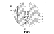
- FIG. 3 is a partially enlarged view of FIG.
- the oil supply amount adjusting mechanism 30 includes a valve seat 31, a needle 32 (valve element), a spring 33, and a needle stopper 34.
- the valve seat 31 has an orifice shape in which the inner diameter decreases as the expansion mechanism 3 is approached.
- a needle 32 is arranged so as to face the valve seat 31.
- the needle 32 has a conical tip.
- a spring 33 is arranged between the valve seat 31 and the needle 32 so that a gap through which oil can flow is formed between the valve seat 31 and the needle 32. As the spring 33 expands and contracts according to the oil pressure fluctuation in the oil supply passage 29, the width of the gap between the valve seat 31 and the needle 32 can be adjusted.
- a needle stop 34 that defines the movable range of the needle 32 is disposed on the opposite side of the valve seat 31 across the needle 32.
- the valve seat 31 or the needle stop 34 may be formed by a part of the shaft 5.
- the oil to be sent to the expansion mechanism 3 flows through the oil supply passage 29 and hits the back surface of the needle 32. Thereafter, the oil flows around the needle 32 and flows toward the valve seat 31.
- the needle 32 is pushed toward the valve seat 31 with a force corresponding to the flow rate of the oil. Further, the needle 32 is pushed back with a force proportional to the displacement of the spring 33. That is, the width of the gap between the valve seat 31 and the needle 32 (the cross-sectional area of the gap) changes according to the oil flow rate.
- the oil feeding capacity of the oil pump 6 increases as the rotational speed of the shaft 5 increases, the resistance to the oil flow increases due to the narrow gap between the valve seat 31 and the needle 32. As a result, the supply amount of oil is limited (optimized).
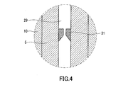
- the oil supply amount adjusting mechanism 30 does not supply more oil than necessary to the expansion mechanism 3. In other words, an appropriate amount of oil can be supplied to the expansion mechanism 3. As a result, heat transfer from the compression mechanism 2 to the expansion mechanism 3 based on oil circulation can be suppressed. Further, since the oil is not excessively supplied to the expansion mechanism 3, it is possible to prevent a large amount of oil from being mixed into the working fluid in the expansion mechanism 3. Therefore, it is possible to prevent a significant decrease in heat exchange efficiency due to excessive oil flowing into the evaporator 102 (see FIG. 10). As shown in FIG. 4, the effect of optimizing the amount of oil supply can be obtained simply by providing the valve seat 31 in the oil supply passage 29. That is, even if an orifice is provided in the oil supply passage 29, the pressure loss at the orifice increases as the oil flow rate increases, so that it is possible to suppress excessive supply of oil to the expansion mechanism 3.
- the oil in the oil supply passage 29 is supplied only to the expansion mechanism 3, but the oil in the oil supply passage 29 may be supplied to the compression mechanism 2.
- FIG. 5 is a longitudinal sectional view of an expander-integrated compressor according to the second embodiment of the present invention.
- the main difference between the expander-integrated compressor 100 ⁇ / b> B of the present embodiment and the expander-integrated compressor 100 ⁇ / b> A of the first embodiment is an oil supply amount adjusting mechanism.
- Members common to the embodiment shown in FIG. 1 are denoted by common reference numerals, and description thereof is omitted.
- FIG. 6 is a partially enlarged view of FIG.
- the shaft 5 is formed with a branch passage 29 s that is branched from the oil supply passage 29 in the radial direction and opened to the outer peripheral surface of the shaft 5.
- An oil supply amount adjusting mechanism 60 is provided in the branch passage 29s. In this way, since the oil supply amount adjusting mechanism 60 can be attached from the outside of the shaft 5, assembly is easier than in the first embodiment. Further, since the branch passage 29s behaves as an oil escape path, it is also suitable when the oil pump is a positive displacement pump.
- the oil supply amount adjusting mechanism 60 includes a valve seat 61, a needle 62, a spring 63, and a needle stop 64.
- the valve seat 61 has an orifice shape whose inner diameter decreases as it approaches the oil supply passage 29, and is disposed in a portion facing the oil supply passage 29 in the branch passage 29s.
- a conical needle 62 is disposed so as to face the valve seat 61.
- the needle 62 can be displaced in a direction approaching the valve seat 61 and a direction away from the valve seat 61 (the radial direction of the shaft 5).
- the needle stop 64 is disposed at a portion of the branch passage 29s facing the outside of the shaft 5.
- the movable range of the needle 62 is defined by the needle stop 64.
- the spring 63 is disposed between the needle 62 and the needle stop 64.
- the bearing member 10 has a bearing portion 10 a that supports the shaft 5.
- the bearing portion 10a covers the outer peripheral surface of the shaft 5 at a position where the branch passage 29s is formed.
- An annular chamber 67 is formed on the inner peripheral surface of the bearing portion 10a.
- the branch passage 29 s opens toward the chamber 67.
- the bearing portion 10a is further formed with an oil discharge path 66 that connects the chamber 67 and the internal space 24 of the sealed container 1 so as to penetrate the bearing portion 10a in the radial direction. Oil can flow from the oil supply passage 29 to the internal space 24 of the sealed container 1 by the branch passage 29s, the chamber 67, and the oil discharge passage 66.
- the closed state is a state in which the branch passage 29s is closed by fitting the needle 62 to the valve seat 61. In the closed state, oil cannot flow through the branch passage 29s.
- the oil supply amount adjusting mechanism 60 is opened.
- the open state is a state in which a gap is generated between the valve seat 61 and the needle 62 when the needle 62 is separated from the valve seat 61. When in the open state, oil can flow through the branch passage 29s.
- the oil supply passage 29 When the internal pressure of the oil supply passage 29 becomes higher than a predetermined pressure, the oil enters the branch passage 29s through the valve seat 61 while pushing the needle 62 down.
- the force with which the oil pushes the needle 62 is proportional to the internal pressure of the oil supply passage 29.
- the outward load applied to the needle 62 by oil or the like (specifically, oil pressure and centrifugal force) in the oil supply passage 29 exceeds the force by which the spring 63 pushes the needle 62 when the oil supply amount adjusting mechanism 60 is in the closed state.
- the oil supply amount adjusting mechanism 60 switches from the closed state to the open state.
- the oil supply amount adjusting mechanism 60 is constituted by a relief valve.
- oil is allowed to escape to the outside of the shaft 5 through the branch passage 29s. Therefore, when the oil supply amount adjusting mechanism 60 is in the open state, the oil flow rate in the oil supply passage 29 differs before and after the position where the oil supply amount adjusting mechanism 60 is provided. Specifically, the flow rate increases between the oil supply amount adjustment mechanism 60 and the oil pump 6, and the flow rate decreases between the expansion mechanism 3 and the oil supply amount adjustment mechanism 60. It is preferable that the portion where the oil flow rate is large is away from the expansion mechanism 3 from the viewpoint of suppressing heat transfer from the compression mechanism 2 to the expansion mechanism 3 based on the circulation of oil. Therefore, it is desirable that a branch passage 29 s is formed in the shaft 5 between the electric motor 4 and the compression mechanism 2.
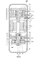
- FIG. 7 is a longitudinal sectional view of an expander-integrated compressor according to a third embodiment of the present invention. As shown in FIG. 7, the main difference between the expander-integrated compressor 100C of the present embodiment and the expander-integrated compressor 100A (FIG. 1) of the first embodiment resides in an oil supply amount adjusting mechanism. .
- FIG. 8 is a partially enlarged view of FIG.
- the shaft 5 is formed with a branch passage 29 t that branches from the oil supply passage 29 in the radial direction and opens to the outer peripheral surface of the shaft 5.
- An oil supply amount adjusting mechanism 70 is provided outside the shaft 5 so that excess oil is guided to the internal space 24 of the sealed container 1 through the branch passage 29t. Since the oil supply amount adjusting mechanism 70 is outside the shaft 5, a larger space can be secured for the oil supply amount adjusting mechanism 70 than in the previous two embodiments.
- This embodiment is common to the second embodiment in that a branch passage 29t is formed in the shaft 5 as an oil escape path.
- the present embodiment is different from the second embodiment in that the oil supply amount adjusting mechanism 70 does not rotate with the shaft 5. Since the branch passage 29t behaves as an oil escape path, it is also suitable when the oil pump is a positive displacement pump.
- the oil supply amount adjusting mechanism 70 is provided inside the bearing member 10.
- the bearing member 10 has a bearing portion 10 a that supports the shaft 5.
- the bearing portion 10a covers the outer peripheral surface of the shaft 5 at a position where the branch passage 29t is formed.
- An annular chamber 77 is formed on the inner peripheral surface of the bearing portion 10a.
- the branch passage 29 t is open toward the chamber 77.
- An oil discharge path 76 is further formed in the bearing portion 10a as a path connecting the chamber 77 and the internal space 24 of the sealed container 1.
- An oil supply amount adjusting mechanism 70 is provided in the oil discharge path 76.
- the oil supply amount adjusting mechanism 70 includes a valve seat 71, a valve body 72, a spring 73, and a valve body stopper 74.
- the oil discharge passage 76 includes a T-shaped section in a direction along the oil flow direction, and a valve seat 71 is disposed in the T-shaped section.
- a valve body 72 having a spherical shape is disposed so as to face the valve seat 71.
- the valve body stopper 74 is disposed on the opposite side of the valve seat 71 with the valve body 72 interposed therebetween.
- a movable range of the valve body 72 is defined by the valve body stopper 74.
- the spring 73 is disposed between the valve body 72 and the valve body stopper 74.
- the structure of the oil supply amount adjusting mechanism 70 may be the same as that in the second embodiment.
- the closed state is a state in which the oil discharge passage 76 is closed by fitting the valve body 72 to the valve seat 71. In the closed state, oil cannot flow through the oil discharge path 76.
- the oil supply amount adjusting mechanism 70 is opened.
- the open state is a state in which a gap is generated between the valve seat 71 and the valve body 72 when the valve body 72 is separated from the valve seat 71. When in the open state, oil can flow through the oil discharge passage 76.
- the valve body 72 When the internal pressure of the oil supply passage 29 becomes higher than a predetermined pressure, the valve body 72 is pushed away by the oil, and the oil discharge passage 76 is opened.
- the force with which the oil pushes the valve body 72 is proportional to the internal pressure of the oil supply passage 29.
- the oil supply amount adjustment mechanism 70 On condition that the load applied to the valve body 72 by the oil in the oil supply passage 29 exceeds the force by which the spring 73 pushes the valve body 72 when the oil supply amount adjustment mechanism 70 is in the closed state, the oil supply amount adjustment mechanism 70 is in the closed state. Switches from open to open.
- the oil supply adjustment mechanism 70 is opened.
- a part of the oil flowing through the oil supply passage 29 is guided to the outside of the shaft 5 through the branch passage 29t. Oil that has come out of the shaft 5 is discharged into the internal space 24 of the sealed container 1 through a chamber 77 and an oil discharge path 76 formed in the bearing portion 10 a of the bearing member 10.
- the oil supply amount adjusting mechanism 70 is constituted by a relief valve.
- oil supply amount adjusting mechanism 70 may be disposed at the outlet of the oil discharge path 76 or may be disposed in the chamber 77.
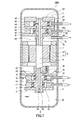
- the axial direction of the shaft 5 is parallel to the horizontal direction.
- An oil reservoir 25 is formed along the longitudinal direction of the sealed container 1.
- a partition wall 27 is provided between the expansion mechanism 3 and the electric motor 4.
- the partition wall 27 partitions the internal space 24 into a space on the expansion mechanism 3 side and a space on the compression mechanism 2 side.
- An electric motor 4 is also arranged in the space on the compression mechanism 2 side.
- This partition wall 27 also has a function of suppressing heat transfer from the compression mechanism 2 and the electric motor 4 to the expansion mechanism 3.
- the partition wall 27 has a passage 27h that allows oil to flow.
- a positive displacement oil pump 26 is provided at the end of the shaft 5.
- An oil pump 26, an expansion mechanism 3, an electric motor 4, and a compression mechanism 2 are arranged in this order along the axial direction of the shaft 5.
- the oil supply amount adjusting mechanism 60 is the same as that described in the third embodiment with reference to FIG.
- the nozzle 26 k of the oil pump 26 extends toward the oil reservoir 25 so that the oil in the oil reservoir 25 can be sucked.
- the oil sucked into the oil pump 26 is supplied through the oil supply passage 29 to the compression mechanism 2 located on the side far from the oil pump 26 with respect to the axial direction of the shaft 5.
- the oil from the oil pump 26 is also supplied to the expansion mechanism 3 located on the near side as viewed from the oil pump 26.
- the oil discharged from the oil supply passage 29 through the oil supply amount adjusting mechanism 60 returns to the space on the expansion mechanism 3 side.
- the oil supply amount adjusting mechanism 60 prevents excessive oil supply. Thereby, the heat transfer from the compression mechanism 2 to the expansion mechanism 3 is suppressed.
- the oil pump 26 is provided on the expansion mechanism 3 side, but the oil pump 26 may be provided on the compression mechanism 2 side.
- an oil supply amount adjusting mechanism 30 (first embodiment) or an oil supply amount adjusting mechanism 70 (third embodiment) may be provided.
- the expander-integrated compressor of the present invention can be suitably used for, for example, an air conditioning apparatus, a hot water supply apparatus, a dryer, or a refrigeration cycle apparatus (heat pump) for a refrigerator-freezer.
- the refrigeration cycle apparatus 110 includes an expander-integrated compressor 100A (100B, 100C, 100D), a radiator 101 for dissipating heat from the refrigerant compressed by the compression mechanism 2, and an expansion mechanism. 3 and an evaporator 114 for evaporating the refrigerant expanded in 3.
- the compression mechanism 2, the heat radiator 101, the expansion mechanism 3, and the evaporator 102 are connected by a pipe to form a refrigerant circuit.
- the heating capacity is reduced due to a decrease in the discharge temperature of the compression mechanism 2 during heating operation by suppressing heat transfer from the compression mechanism 2 to the expansion mechanism 3 Further, it is possible to prevent a decrease in cooling capacity due to an increase in the discharge temperature of the expansion mechanism 3 during the cooling operation. As a result, the coefficient of performance of the air conditioner is improved.
Landscapes
- Engineering & Computer Science (AREA)
- Mechanical Engineering (AREA)
- General Engineering & Computer Science (AREA)
- Applications Or Details Of Rotary Compressors (AREA)
- Compressors, Vaccum Pumps And Other Relevant Systems (AREA)
- Compressor (AREA)
Abstract
Description
作動流体を圧縮するための圧縮機構と、
作動流体から動力を回収するための膨張機構と、
前記膨張機構で回収された動力が前記圧縮機構に伝達されるように前記圧縮機構と前記膨張機構とを連結しているシャフトと、
前記圧縮機構および前記膨張機構が上下に配列するように前記圧縮機構、前記膨張機構および前記シャフトを収容しており、底部がオイル貯まりとして利用され、圧縮後の作動流体で内部空間が満たされる密閉容器と、
前記シャフトの下部に設けられたオイルポンプと、
前記オイルポンプによって前記オイル貯まりのオイルを前記密閉容器内の上側に位置している前記圧縮機構または前記膨張機構に供給するために、軸方向に延びるように前記シャフトの内部に形成された給油路と、
前記密閉容器内の上側に位置している前記圧縮機構または前記膨張機構よりも下方に設けられ、前記給油路を通じて前記密閉容器内の上側に位置している前記圧縮機構または前記膨張機構に供給されるオイルの量を調節するための給油量調節機構と、
を備えた、膨張機一体型圧縮機を提供する。
上記本発明の膨張機一体型圧縮機と、
前記膨張機一体型圧縮機の前記圧縮機構で圧縮された冷媒を放熱させるための放熱器と、
前記膨張機一体型圧縮機の前記膨張機構で膨張した冷媒を蒸発させるための蒸発器と、
を備えた、冷凍サイクル装置を提供する。
作動流体を圧縮するための圧縮機構と、
作動流体から動力を回収するための膨張機構と、
前記膨張機構で回収された動力が前記圧縮機構に伝達されるように前記圧縮機構と前記膨張機構とを連結しているシャフトと、
前記圧縮機構、前記膨張機構および前記シャフトを収容しており、底部がオイル貯まりとして利用され、圧縮後の作動流体で内部空間が満たされる密閉容器と、
前記シャフトの端部に設けられたオイルポンプと、
前記オイルポンプによって前記オイル貯まりのオイルを前記シャフトの軸方向に関して前記オイルポンプから見て遠い側に位置している前記圧縮機構または前記膨張機構に供給するために、軸方向に延びるように前記シャフトの内部に形成された給油路と、
前記圧縮機構または前記膨張機構に前記給油路を通じて供給されるオイルの量を調節するための給油量調節機構と、
を備えた、膨張機一体型圧縮機を提供する。
図1は、本発明の第1実施形態にかかる膨張機一体型圧縮機の縦断面図である。膨張機一体型圧縮機100Aは、密閉容器1、圧縮機構2、膨張機構3、電動機4、シャフト5、オイルポンプ6および給油量調節機構30を備えている。圧縮機構2は、密閉容器1内の下側に配置されている。膨張機構3は、密閉容器1内の上側に配置されている。圧縮機構2と膨張機構3との間に電動機4が配置されている。圧縮機構2、電動機4および膨張機構3は、動力伝達がなされるようにシャフト5によって連結されている。オイルポンプ6はシャフト5の下部に設けられている。給油量調節機構30は、膨張機構3に供給されるオイルの量を調節するためのものである。本実施形態では、給油量調節機構30として、調節弁(典型的にはニードル弁)が採用されている。
図5は、本発明の第2実施形態にかかる膨張機一体型圧縮機の縦断面図である。図5に示すように、本実施形態の膨張機一体型圧縮機100Bと、第1実施形態の膨張機一体型圧縮機100Aとの主な相違点は、給油量調節機構にある。図1に示す実施形態と共通の部材には共通の符号を付し、説明を省略することとする。
図7は、本発明の第3実施形態にかかる膨張機一体型圧縮機の縦断面図である。図7に示すように、本実施形態の膨張機一体型圧縮機100Cと、第1実施形態の膨張機一体型圧縮機100A(図1)との主な相違点は、給油量調節機構にある。
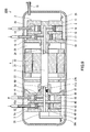
図9に示すように、本実施形態の膨張機一体型圧縮機100Dは、シャフト5の軸方向が水平方向に平行である。密閉容器1の長手方向に沿ってオイル貯まり25が形成されている。膨張機構3と電動機4との間には隔壁27が設けられている。隔壁27は、内部空間24を膨張機構3側の空間と圧縮機構2側の空間とに仕切っている。圧縮機構2側の空間には電動機4も配置されている。この隔壁27にも圧縮機構2および電動機4から膨張機構3への熱移動を抑制する機能がある。隔壁27は、オイルの流通を許容する通路27hを有する。
Claims (13)
- 作動流体を圧縮するための圧縮機構と、
作動流体から動力を回収するための膨張機構と、
前記膨張機構で回収された動力が前記圧縮機構に伝達されるように前記圧縮機構と前記膨張機構とを連結しているシャフトと、
前記圧縮機構および前記膨張機構が上下に配列するように前記圧縮機構、前記膨張機構および前記シャフトを収容しており、底部がオイル貯まりとして利用され、圧縮後の作動流体で内部空間が満たされる密閉容器と、
前記シャフトの下部に設けられたオイルポンプと、
前記オイルポンプによって前記オイル貯まりのオイルを前記密閉容器内の上側に位置している前記圧縮機構または前記膨張機構に供給するために、軸方向に延びるように前記シャフトの内部に形成された給油路と、
前記密閉容器内の上側に位置している前記圧縮機構または前記膨張機構よりも下方に設けられ、前記給油路を通じて前記密閉容器内の上側に位置している前記圧縮機構または前記膨張機構に供給されるオイルの量を調節するための給油量調節機構と、
を備えた、膨張機一体型圧縮機。 - 前記給油路から径方向に分岐して前記シャフトの外周面に開口している分岐通路が前記シャフトに形成され、
前記給油量調節機構が、前記分岐通路内に設けられている、請求項1に記載の膨張機一体型圧縮機。 - 前記圧縮機構と前記膨張機構との間に配置され、前記シャフトを駆動するための電動機をさらに備え、
前記電動機と、前記密閉容器内の下側に位置している前記圧縮機構または前記膨張機構との間において、前記シャフトに前記分岐通路が形成されている、請求項2に記載の膨張機一体型圧縮機。 - 前記給油量調節機構は、前記給油路を通じて前記圧縮機構または前記膨張機構に供給されるオイルの量が前記シャフトの回転数の増大に追従するのを妨げる構造を含む、請求項1に記載の膨張機一体型圧縮機。
- 前記給油量調節機構が、オリフィス、ニードル弁またはリリーフ弁を含む、請求項1に記載の膨張機一体型圧縮機。
- 前記給油量調節機構が、前記給油路内に設けられている、請求項1に記載の膨張機一体型圧縮機。
- 前記給油路から径方向に分岐して前記シャフトの外周面に開口している分岐通路が前記シャフトに形成され、
オイルが前記分岐通路を通じて前記密閉容器の内部空間に導かれるように、前記給油量調節機構が前記シャフトの外部に設けられている、請求項1に記載の膨張機一体型圧縮機。 - 前記給油量調節機構は、弁座と、前記弁座に向かい合う位置に配置された弁体と、前記給油路におけるオイルの圧力変動に応じて伸縮することによって前記弁座と前記弁体との隙間の広さを調節するためのバネとを含む、請求項1に記載の膨張機一体型圧縮機。
- 前記弁体の形状が球状である、請求項8に記載の膨張機一体型圧縮機。
- 前記分岐通路が形成されている位置で前記シャフトに面するように設けられたチャンバーをさらに備え、
前記給油量調節機構が前記チャンバー内またはそのチャンバーと前記密閉容器の内部空間と結ぶ経路上に配置されている、請求項7に記載の膨張機一体型圧縮機。 - 前記オイルポンプが速度型ポンプである、請求項1に記載の膨張機一体型圧縮機。
- 請求項1に記載の膨張機一体型圧縮機と、
前記膨張機一体型圧縮機の前記圧縮機構で圧縮された冷媒を放熱させるための放熱器と、
前記膨張機一体型圧縮機の前記膨張機構で膨張した冷媒を蒸発させるための蒸発器と、
を備えた、冷凍サイクル装置。 - 作動流体を圧縮するための圧縮機構と、
作動流体から動力を回収するための膨張機構と、
前記膨張機構で回収された動力が前記圧縮機構に伝達されるように前記圧縮機構と前記膨張機構とを連結しているシャフトと、
前記圧縮機構、前記膨張機構および前記シャフトを収容しており、底部がオイル貯まりとして利用され、圧縮後の作動流体で内部空間が満たされる密閉容器と、
前記シャフトの端部に設けられたオイルポンプと、
前記オイルポンプによって前記オイル貯まりのオイルを前記シャフトの軸方向に関して前記オイルポンプから見て遠い側に位置している前記圧縮機構または前記膨張機構に供給するために、軸方向に延びるように前記シャフトの内部に形成された給油路と、
前記圧縮機構または前記膨張機構に前記給油路を通じて供給されるオイルの量を調節するための給油量調節機構と、
を備えた、膨張機一体型圧縮機。
Priority Applications (4)
| Application Number | Priority Date | Filing Date | Title |
|---|---|---|---|
| CN2009801020298A CN101910563A (zh) | 2008-01-29 | 2009-01-27 | 膨胀机一体型压缩机及使用该压缩机的制冷循环装置 |
| JP2009551430A JPWO2009096167A1 (ja) | 2008-01-29 | 2009-01-27 | 膨張機一体型圧縮機およびそれを用いた冷凍サイクル装置 |
| US12/865,085 US20100326124A1 (en) | 2008-01-29 | 2009-01-27 | Expander-integrated compressor and refrigeration cycle apparatus using the same |
| EP09705176A EP2241719A1 (en) | 2008-01-29 | 2009-01-27 | Expander-integrated compressor and refrigeration cycle device using the same |
Applications Claiming Priority (2)
| Application Number | Priority Date | Filing Date | Title |
|---|---|---|---|
| JP2008018354 | 2008-01-29 | ||
| JP2008-018354 | 2008-01-29 |
Publications (1)
| Publication Number | Publication Date |
|---|---|
| WO2009096167A1 true WO2009096167A1 (ja) | 2009-08-06 |
Family
ID=40912523
Family Applications (1)
| Application Number | Title | Priority Date | Filing Date |
|---|---|---|---|
| PCT/JP2009/000295 Ceased WO2009096167A1 (ja) | 2008-01-29 | 2009-01-27 | 膨張機一体型圧縮機およびそれを用いた冷凍サイクル装置 |
Country Status (5)
| Country | Link |
|---|---|
| US (1) | US20100326124A1 (ja) |
| EP (1) | EP2241719A1 (ja) |
| JP (1) | JPWO2009096167A1 (ja) |
| CN (1) | CN101910563A (ja) |
| WO (1) | WO2009096167A1 (ja) |
Cited By (1)
| Publication number | Priority date | Publication date | Assignee | Title |
|---|---|---|---|---|
| US9402222B2 (en) | 2009-09-25 | 2016-07-26 | Sony Corporation | Communication system, relay device, communication terminal, and base station |
Families Citing this family (14)
| Publication number | Priority date | Publication date | Assignee | Title |
|---|---|---|---|---|
| WO2009141956A1 (ja) * | 2008-05-23 | 2009-11-26 | パナソニック株式会社 | 流体機械および冷凍サイクル装置 |
| KR101409876B1 (ko) * | 2008-08-22 | 2014-06-20 | 엘지전자 주식회사 | 용량가변형 로터리 압축기 및 이를 적용한 냉동기기 및 그 운전 방법 |
| TWI463073B (zh) * | 2011-12-22 | 2014-12-01 | Fu Sheng Ind Co Ltd | 多段式熱泵壓縮機 |
| CN103452847B (zh) * | 2013-08-19 | 2015-11-18 | 广东美芝制冷设备有限公司 | 旋转式压缩机及具有该旋转式压缩机的冷冻循环装置 |
| ES2612232T3 (es) * | 2014-06-05 | 2017-05-12 | Wabco Europe Bvba | Bomba de vacío y sistema de una bomba de vacío y un motor |
| CN106196685A (zh) * | 2016-07-22 | 2016-12-07 | 西安交通大学 | 一种跨临界二氧化碳制冷系统 |
| CN106247657A (zh) * | 2016-07-22 | 2016-12-21 | 西安交通大学 | 一种二氧化碳电冰箱制冷系统 |
| CN107387419B (zh) * | 2017-08-22 | 2020-12-22 | 广东美芝制冷设备有限公司 | 控油组件、泵和旋转式压缩机 |
| CN108050066A (zh) * | 2017-12-22 | 2018-05-18 | 珠海格力节能环保制冷技术研究中心有限公司 | 一种压缩机及制冷循环装置 |
| CN108518276A (zh) * | 2018-03-26 | 2018-09-11 | 陈平武 | 体外内燃式发动机 |
| CN111946621A (zh) * | 2020-09-14 | 2020-11-17 | 松下压缩机(大连)有限公司 | 变频压缩机供油机构 |
| CN112343797B (zh) * | 2020-10-09 | 2023-06-13 | 珠海格力节能环保制冷技术研究中心有限公司 | 一种曲轴泵油组件、曲轴组件及压缩机 |
| CN113565968B (zh) * | 2021-08-16 | 2025-06-06 | 裕克施乐塑料制品(太仓)有限公司 | 一种活塞式电子膨胀阀 |
| CN120344759A (zh) * | 2022-10-24 | 2025-07-18 | 能升公司 | 单向热泵系统 |
Citations (4)
| Publication number | Priority date | Publication date | Assignee | Title |
|---|---|---|---|---|
| JPH025787A (ja) * | 1988-06-22 | 1990-01-10 | Mitsubishi Electric Corp | スクロール圧縮機 |
| JPH03237287A (ja) * | 1990-02-14 | 1991-10-23 | Daikin Ind Ltd | スクロール形圧縮機 |
| JP2000213480A (ja) * | 1999-01-19 | 2000-08-02 | Lg Electronics Inc | スクロ―ル圧縮機 |
| JP2005299632A (ja) | 2004-03-17 | 2005-10-27 | Daikin Ind Ltd | 流体機械 |
Family Cites Families (7)
| Publication number | Priority date | Publication date | Assignee | Title |
|---|---|---|---|---|
| US8127567B2 (en) * | 2005-06-29 | 2012-03-06 | Panasonic Corporation | Shaft coupling and arrangement for fluid machine and refrigeration cycle apparatus |
| US8186179B2 (en) * | 2006-05-17 | 2012-05-29 | Panasonic Corporation | Expander-compressor unit |
| EP2077426A4 (en) * | 2006-10-25 | 2012-03-07 | Panasonic Corp | COOLING CYCLE DEVICE AND LIQUID MACHINE USED THEREFOR |
| JP4969648B2 (ja) * | 2007-05-16 | 2012-07-04 | パナソニック株式会社 | 膨張機一体型圧縮機およびそれを備えた冷凍サイクル装置 |
| EP2154330A4 (en) * | 2007-05-16 | 2012-11-21 | Panasonic Corp | COLD PROCESSING DEVICE AND FLOW MACHINE USED THEREFOR |
| CN101868597B (zh) * | 2007-11-21 | 2012-05-30 | 松下电器产业株式会社 | 膨胀机一体型压缩机 |
| CN101855422B (zh) * | 2007-11-21 | 2012-05-30 | 松下电器产业株式会社 | 膨胀机一体型压缩机 |
-
2009
- 2009-01-27 WO PCT/JP2009/000295 patent/WO2009096167A1/ja not_active Ceased
- 2009-01-27 EP EP09705176A patent/EP2241719A1/en not_active Withdrawn
- 2009-01-27 CN CN2009801020298A patent/CN101910563A/zh active Pending
- 2009-01-27 US US12/865,085 patent/US20100326124A1/en not_active Abandoned
- 2009-01-27 JP JP2009551430A patent/JPWO2009096167A1/ja active Pending
Patent Citations (4)
| Publication number | Priority date | Publication date | Assignee | Title |
|---|---|---|---|---|
| JPH025787A (ja) * | 1988-06-22 | 1990-01-10 | Mitsubishi Electric Corp | スクロール圧縮機 |
| JPH03237287A (ja) * | 1990-02-14 | 1991-10-23 | Daikin Ind Ltd | スクロール形圧縮機 |
| JP2000213480A (ja) * | 1999-01-19 | 2000-08-02 | Lg Electronics Inc | スクロ―ル圧縮機 |
| JP2005299632A (ja) | 2004-03-17 | 2005-10-27 | Daikin Ind Ltd | 流体機械 |
Cited By (3)
| Publication number | Priority date | Publication date | Assignee | Title |
|---|---|---|---|---|
| US9402222B2 (en) | 2009-09-25 | 2016-07-26 | Sony Corporation | Communication system, relay device, communication terminal, and base station |
| US10063279B2 (en) | 2009-09-25 | 2018-08-28 | Sony Corporation | Communication system, relay device, communication terminal, and base station |
| US10965341B2 (en) | 2009-09-25 | 2021-03-30 | Sony Corporation | Communication system, relay device, communication terminal, and base station |
Also Published As
| Publication number | Publication date |
|---|---|
| EP2241719A1 (en) | 2010-10-20 |
| JPWO2009096167A1 (ja) | 2011-05-26 |
| US20100326124A1 (en) | 2010-12-30 |
| CN101910563A (zh) | 2010-12-08 |
Similar Documents
| Publication | Publication Date | Title |
|---|---|---|
| WO2009096167A1 (ja) | 膨張機一体型圧縮機およびそれを用いた冷凍サイクル装置 | |
| US8689581B2 (en) | Rotary-type fluid machine and refrigeration cycle apparatus | |
| KR100757179B1 (ko) | 유체기계 | |
| JP5631398B2 (ja) | ロータリ圧縮機及び冷凍サイクル装置 | |
| CN102575674B (zh) | 回转式压缩机及制冷循环装置 | |
| EP2093374A1 (en) | Fluid machine and refrigeration cycle device | |
| JP5014346B2 (ja) | 膨張機一体型圧縮機およびそれを備えた冷凍サイクル装置 | |
| WO2009136488A1 (ja) | 流体機械 | |
| JP2005201145A (ja) | スクロール型圧縮機 | |
| JP5506953B2 (ja) | 冷媒圧縮機 | |
| CN205977674U (zh) | 旋转压缩机及具有其的制冷循环装置 | |
| JP4013552B2 (ja) | 密閉形圧縮機 | |
| US8245528B2 (en) | Fluid machine | |
| JP2006132332A (ja) | 流体機械 | |
| JP2012036862A (ja) | 密閉型圧縮機及び冷凍サイクル装置 | |
| JP4492284B2 (ja) | 流体機械 | |
| WO2021149180A1 (ja) | 圧縮機 | |
| JP5115355B2 (ja) | 流体機械 | |
| JP2022147381A (ja) | 密閉型ロータリ圧縮機及びこれを用いた冷蔵庫 | |
| JP4924450B2 (ja) | 膨張機 | |
| JP2009013798A (ja) | 膨張機一体型圧縮機 |
Legal Events
| Date | Code | Title | Description |
|---|---|---|---|
| WWE | Wipo information: entry into national phase |
Ref document number: 200980102029.8 Country of ref document: CN |
|
| 121 | Ep: the epo has been informed by wipo that ep was designated in this application |
Ref document number: 09705176 Country of ref document: EP Kind code of ref document: A1 |
|
| DPE1 | Request for preliminary examination filed after expiration of 19th month from priority date (pct application filed from 20040101) | ||
| WWE | Wipo information: entry into national phase |
Ref document number: 2009551430 Country of ref document: JP |
|
| WWE | Wipo information: entry into national phase |
Ref document number: 12865085 Country of ref document: US |
|
| NENP | Non-entry into the national phase |
Ref country code: DE |
|
| WWE | Wipo information: entry into national phase |
Ref document number: 2009705176 Country of ref document: EP |