WO2009096183A1 - 表示装置 - Google Patents
表示装置 Download PDFInfo
- Publication number
- WO2009096183A1 WO2009096183A1 PCT/JP2009/000342 JP2009000342W WO2009096183A1 WO 2009096183 A1 WO2009096183 A1 WO 2009096183A1 JP 2009000342 W JP2009000342 W JP 2009000342W WO 2009096183 A1 WO2009096183 A1 WO 2009096183A1
- Authority
- WO
- WIPO (PCT)
- Prior art keywords
- information
- menu
- unit
- display device
- page
- Prior art date
- Legal status (The legal status is an assumption and is not a legal conclusion. Google has not performed a legal analysis and makes no representation as to the accuracy of the status listed.)
- Ceased
Links
Images



Classifications
-
- G—PHYSICS
- G06—COMPUTING OR CALCULATING; COUNTING
- G06F—ELECTRIC DIGITAL DATA PROCESSING
- G06F21/00—Security arrangements for protecting computers, components thereof, programs or data against unauthorised activity
- G06F21/30—Authentication, i.e. establishing the identity or authorisation of security principals
- G06F21/305—Authentication, i.e. establishing the identity or authorisation of security principals by remotely controlling device operation
-
- G—PHYSICS
- G08—SIGNALLING
- G08C—TRANSMISSION SYSTEMS FOR MEASURED VALUES, CONTROL OR SIMILAR SIGNALS
- G08C19/00—Electric signal transmission systems
-
- H—ELECTRICITY
- H04—ELECTRIC COMMUNICATION TECHNIQUE
- H04L—TRANSMISSION OF DIGITAL INFORMATION, e.g. TELEGRAPHIC COMMUNICATION
- H04L12/00—Data switching networks
- H04L12/28—Data switching networks characterised by path configuration, e.g. LAN [Local Area Networks] or WAN [Wide Area Networks]
- H04L12/2803—Home automation networks
- H04L12/2807—Exchanging configuration information on appliance services in a home automation network
- H04L12/2809—Exchanging configuration information on appliance services in a home automation network indicating that an appliance service is present in a home automation network
-
- H—ELECTRICITY
- H04—ELECTRIC COMMUNICATION TECHNIQUE
- H04L—TRANSMISSION OF DIGITAL INFORMATION, e.g. TELEGRAPHIC COMMUNICATION
- H04L12/00—Data switching networks
- H04L12/28—Data switching networks characterised by path configuration, e.g. LAN [Local Area Networks] or WAN [Wide Area Networks]
- H04L12/2803—Home automation networks
- H04L12/2807—Exchanging configuration information on appliance services in a home automation network
- H04L12/281—Exchanging configuration information on appliance services in a home automation network indicating a format for calling an appliance service function in a home automation network
-
- H—ELECTRICITY
- H04—ELECTRIC COMMUNICATION TECHNIQUE
- H04L—TRANSMISSION OF DIGITAL INFORMATION, e.g. TELEGRAPHIC COMMUNICATION
- H04L12/00—Data switching networks
- H04L12/28—Data switching networks characterised by path configuration, e.g. LAN [Local Area Networks] or WAN [Wide Area Networks]
- H04L12/2803—Home automation networks
- H04L12/2816—Controlling appliance services of a home automation network by calling their functionalities
- H04L12/282—Controlling appliance services of a home automation network by calling their functionalities based on user interaction within the home
-
- G—PHYSICS
- G06—COMPUTING OR CALCULATING; COUNTING
- G06F—ELECTRIC DIGITAL DATA PROCESSING
- G06F21/00—Security arrangements for protecting computers, components thereof, programs or data against unauthorised activity
- G06F21/30—Authentication, i.e. establishing the identity or authorisation of security principals
-
- G—PHYSICS
- G06—COMPUTING OR CALCULATING; COUNTING
- G06F—ELECTRIC DIGITAL DATA PROCESSING
- G06F40/00—Handling natural language data
- G06F40/10—Text processing
- G06F40/103—Formatting, i.e. changing of presentation of documents
-
- G—PHYSICS
- G06—COMPUTING OR CALCULATING; COUNTING
- G06F—ELECTRIC DIGITAL DATA PROCESSING
- G06F40/00—Handling natural language data
- G06F40/10—Text processing
- G06F40/166—Editing, e.g. inserting or deleting
- G06F40/174—Form filling; Merging
-
- G—PHYSICS
- G06—COMPUTING OR CALCULATING; COUNTING
- G06V—IMAGE OR VIDEO RECOGNITION OR UNDERSTANDING
- G06V30/00—Character recognition; Recognising digital ink; Document-oriented image-based pattern recognition
- G06V30/40—Document-oriented image-based pattern recognition
- G06V30/41—Analysis of document content
- G06V30/412—Layout analysis of documents structured with printed lines or input boxes, e.g. business forms or tables
-
- G—PHYSICS
- G08—SIGNALLING
- G08C—TRANSMISSION SYSTEMS FOR MEASURED VALUES, CONTROL OR SIMILAR SIGNALS
- G08C2201/00—Transmission systems of control signals via wireless link
- G08C2201/30—User interface
-
- G—PHYSICS
- G08—SIGNALLING
- G08C—TRANSMISSION SYSTEMS FOR MEASURED VALUES, CONTROL OR SIMILAR SIGNALS
- G08C2201/00—Transmission systems of control signals via wireless link
- G08C2201/40—Remote control systems using repeaters, converters, gateways
- G08C2201/42—Transmitting or receiving remote control signals via a network
Definitions
- the present invention relates to a display device connected to a controlled device via a network.
- controlled devices In recent years, it has become possible to use household electrical appliances controlled through a network (hereinafter referred to as “controlled devices”). For this reason, a display device for controlling a plurality of controlled devices connected to a network has been proposed.
- the display device includes a communication unit that transmits and receives data by connecting to a network, an information acquisition unit, a display unit that displays an operation screen, and an operation unit that operates the operation screen displayed on the display unit.
- the information acquisition unit detects a controlled device connected to the network, and acquires device ID information, product category information, and URL (Uniform Resource Locator) information of the detected controlled device.
- the information acquisition unit acquires an operation screen for operating the controlled device from the URL specified by the URL information.
- the display device displays a list of controlled devices for each product category on the display unit, and further obtains an operation screen for operating the controlled device selected by the user from the list from the URL destination. Is displayed on the display. Then, the user operates the controlled device using this operation screen.
- a display device is disclosed in Patent Document 1, for example.
- the user When a user operates a controlled device using such a conventional display device, first, the user selects a target controlled device from a controlled device list for each product category displayed on the display device. Next, the display device displays the URL information of the controlled device selected by the user. The display device acquires and displays the operation screen at the URL specified by the user. That is, the user can grasp the function contents (viewing / operation setting) that can be operated for the first time after confirming the operation screen acquired from the URL destination. For this reason, for example, even when the user simply wants to see the image of a certain camera, the target controlled device is searched from the product category list. Thus, each time the user needs to check whether or not the operation screen can be downloaded and viewed from the URL destination of the controlled device. Therefore, there are problems that the operation burden is large for the user, the operation time is long, and the operation of the controlled device is not easy. JP 2003-309984 A
- the present invention provides a display device that can easily operate a plurality of controlled devices connected to a network.
- the display device is a display device connected to the controlled device via a network, and includes an information acquisition unit that acquires operation related information including operation information and URL information corresponding to the operation information from the controlled device, and based on the operation information.
- an information classifying unit for classifying URL information into a plurality of function groups, a menu generating unit for generating a menu page for selecting a controlled device for each function group, a display unit for displaying the menu page, and the menu page And a page operation unit for accessing the corresponding URL information.
- FIG. 1 is a block diagram showing the overall configuration of the device control system according to Embodiment 1 of the present invention.
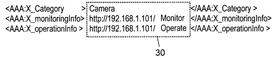
- FIG. 2 is a diagram illustrating an example in which operation-related information is described in an extended area of the UPnP specification in the embodiment.
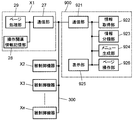
- FIG. 3 is a block diagram showing the configuration of the control device and the controlled device in the embodiment.
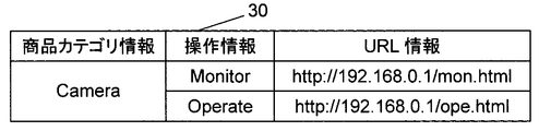
- FIG. 4 is a diagram showing a configuration of operation related information stored and held in the controlled device in the embodiment.
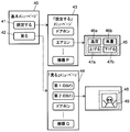
- FIG. 5 is a transition diagram showing an example of menu generation in the display device of the embodiment.
- FIG. 6 is a diagram for explaining a control sequence in the same embodiment.
- FIG. 7 is a diagram showing a configuration of operation correspondence information of the controlled device according to Embodiment 2 of the present invention.
- FIG. 8 is a relationship diagram showing the correspondence between the menu layout and the operation commands in the display device according to the embodiment.
- FIG. 9 is a block diagram illustrating a configuration of a page operation unit in a display device according to another embodiment.
- FIG. 10 is a block diagram illustrating a configuration of a display unit in a display device according to another embodiment.
- FIG. 1 is a block diagram showing an overall configuration of a device control system 100 in the present embodiment.
- FIG. 2 is a diagram illustrating an example in which operation-related information is described in the UPnP specification extension area according to the first embodiment.
- FIG. 3 is a block diagram showing the configuration of the control device and the controlled device in the first embodiment.
- the device control system 100 includes a controlled device and a control device that controls the controlled device.
- a controlled device for example, a first camera 400, a second camera 500, a door phone 600, an air conditioner 700, a lighting device 800, and a television receiver having the function of a control device. (Hereinafter referred to as “TV”) or the like is connected.
- TV television receiver
- control device and the controlled device communicate with each other using TCP / IP (Transmission Control Protocol / Internet Protocol).
- TCP / IP Transmission Control Protocol / Internet Protocol
- the control device and the controlled device notify all devices connected to the network 300 that a new device has been connected and the contents of the function by multicast. Thereafter, the control device and the controlled device notify the network 300 of their existence at regular intervals.
- control device receives and stores a message from the controlled device, and can control the controlled device based on the stored list.
- the control device can check the connection status of the devices connected to the network 300 at regular intervals and update the list to the latest status.
- the controlled device controls the message that describes the device information and service information (XML base) such as what product category and what function each device has. Communicate with the device. For this exchange, hypertext (HTTP protocol) is used.
- HTTP protocol Hypertext
- the operation related information of the controlled device is passed to the controlling device using the UPnP specification extension area.
- operation related information 30 of the controlled device is described in an extended area of DDD (Device Description Document) which is UPnP device information.
- DDD Device Description Document
- product category information such as a camera
- operation information indicating an operation function such as Monitor and Operate
- URL information indicating an acquisition destination of an operation screen of the operation function. it can.
- messages are exchanged between the control device and the controlled device in accordance with a predetermined specification.
- control device can use the operation-related information specific to the controlled device and the function specific to the controlled device using the operation-related information 30 of the controlled device.
- the first camera 400 and the second camera 500 can photograph a subject with a camera.
- the first camera 400 and the second camera 500 can output a video obtained by shooting with the “shooting function” to the display device 900 via the network 300.
- the door phone 600 is installed at a front door or the like and can talk with a visitor.
- the door phone 600 further includes a camera, and photographs a visitor with this camera.
- door phone 600 has a “call function” and a “photographing function”.
- the intercom 600 can output video and audio obtained by using the “call function” and “photographing function” to the display device 900 via the network 300.
- the air conditioner 700 can adjust the temperature and humidity of the room using the setting function.
- the air conditioner 700 has functions such as “cooling”, “heating”, “dehumidification”, and “air blowing”, and is operated by a dedicated remote controller (hereinafter referred to as “remote control”).
- the air conditioner 700 is also operated from the display device 900 via the network 300.
- the lighting device 800 can adjust the brightness of the room using the brightness adjustment function.
- the device control system 100 can control the first camera 400, the second camera 500, the door phone 600, the air conditioner 700, and the lighting device 800 from the display device 900 via the network 300.
- the display device 900 acquires operation-related information such as device ID information, product category information, operation information, and URL information from each controlled device. Then, after specifying the operation information (function) included in the operation related information, the display device 900 acquires the operation screen at the URL destination from the corresponding URL information, and responds based on the operation screen.
- the controlled device can be operated.
- definition information conforming to the ECHONET (Energy Conservation and Homecare NETwork) specification can be used as a unified control command when controlling the controlled device. In this way, control can be performed without knowing information about the controlled device in advance.
- the controlled device is not limited to the ECHONET specification and may be any device that can perform unified control in accordance with a known interconnection specification.
- the interconnection specifications may include, for example, HAVi (Home Audio / Video Interoperability), HBS (Home Bus System), IEEE 1394 serial bus, and the like.
- categories include “sensor-related equipment”, “housing / facility-related equipment”, “health-related equipment”, “management / operation-related equipment”, etc. .
- controlled devices belonging to each are defined.
- devices such as “home air conditioner”, “cool air fan”, “fan”, “ventilator”, “air purifier” are defined as classes.
- Controlled devices conforming to the ECHONET specification are required to incorporate the category and class identification codes described above, so that the category code and class code can be read directly from each controlled device via the network 300. It has become.
- the class has an attribute identifier called EPC (Echonet Property Code), and an identification code expressing the attribute of each controlled device is assigned.
- EPC Echonet Property Code
- Each EPC defines an attribute value called EDT (Echonet Property Value Data).
- EDT Echonet Property Value Data
- each EPC defines its own EDT.
- the class “household air conditioner” has an EPC called “operation mode”, and this EPC has EDTs “cooling”, “heating”, “dehumidifying”, “fan”, and “automatic”. Is defined.
- control device can acquire identification information and operation-related information of each controlled device, and can acquire and control definition information for controlling each controlled device in a unified manner.
- the display apparatus 900 as a control device includes a communication unit 921, an information acquisition unit 922, an information classification unit 923, a menu generation unit 924, a display unit 925, and a page operation unit 926, as shown in FIG. .
- the communication unit 921 communicates with the controlled devices X1 to Xn connected to the network 300.
- the controlled devices X1 to Xn are, for example, any of the first camera 400, the second camera 500, the door phone 600, the air conditioner 700, and the lighting device 800 in FIG.
- the information acquisition unit 922 acquires operation related information from the controlled devices X1 to Xn via the communication unit 921.
- the controlled devices X1 to Xn connected to the network 300 may be changed.
- the information acquisition unit 922 checks the connection status of the controlled devices X1 to Xn connected to the network 300 every predetermined period. Then, the information acquisition unit 922 acquires operation-related information including identification information, operation information, and URL information corresponding to the operation information of the latest controlled devices X1 to Xn connected to the network 300, and has already been acquired. Update the operation related information.
- the information classification unit 923 classifies the URL information into a plurality of function groups based on the operation information included in the operation related information of each of the controlled devices X1 to X acquired by the information acquisition unit 922. Note that when the operation related information is updated, the information classification unit 923 reclassifies the operation related information into a plurality of function groups again based on the updated operation related information.
- the menu generation unit 924 dynamically generates a menu page for each function group classified by the information classification unit 923.
- the menu generation unit 924 dynamically generates a menu page according to the reclassified function group. Details of menu page generation by the menu generation unit 924 will be described later.
- the display unit 925 displays the menu page generated by the menu generation unit 924.
- the page operation unit 926 operates a menu page displayed on the display unit 925 and a URL screen transmitted from the page processing unit 29.
- each of the controlled devices X1 to Xn includes a communication unit 27, an operation related information storage unit 28, and a page processing unit 29.
- the communication unit 27 communicates with the display device 900 connected to the network 300.
- the operation related information storage unit 28 stores device identification information, operation related information, and the like. That is, the operation related information storage unit 28 stores and holds definition information such as device ID information, product category information, operation information, and URL information.
- FIG. 4 is an example of stored information.
- the page processing unit 29 When the page processing unit 29 receives a display request for an operation screen page based on URL information from the display device 900, an operation screen page specified by the URL information (for example, a page described in HTML (Hyper Text Markup Language)) is displayed. It is sent via the communication unit 27.
- the controlled devices X1 to Xn receive the operation command from the display device 900, the controlled devices X1 to Xn execute the corresponding operation command.
- the controlled devices X1 to Xn each have a unique function and have operation-related information corresponding to this unique function.
- the controlled devices X1 to Xn store and hold operation-related information 30 having product category information, operation information, and URL information related to the operation information.
- the controlled devices X1 to Xn as the operation related information 30, in addition to the operation information and the URL information related to the operation information, the device ID information, the product category, Definition information such as information is returned to the display device 900.
- an extended area of the UPnP specification is used.
- FIG. 5 is a transition diagram illustrating an example of menu generation in the display device 900 according to the first embodiment.
- the information classification unit 923 extracts the viewing function (Monitor) and the operation setting function (Operate) from the operation information included in the operation related information 30.
- URL information is grouped and classified into a viewing function group related to the viewing function and an operation setting function group related to the operation setting function will be described.
- the menu generation unit 924 first generates a basic menu page 40 for allowing the user to select a function group. By viewing the basic menu page 40, the user can confirm only the device having the target function.
- the basic menu page 40 includes, for example, a “set” menu 41 for allowing the user to select an operation setting function according to the function group grouped by the information classification unit 923, and a user to select a viewing function.
- a “view” menu 42 is created. This “view” menu 42 is an example of a viewing function group related to the viewing function described above.
- This “set” menu 41 is an example of an operation setting function group related to the above-described operation setting function.
- the menu generating unit 924 operates as an operation setting function among the controlled devices X1 to Xn connected to the network 300 as the “set” menu page 43 when the “set” menu 41 is selected by the user. Create a list menu of devices with.
- the menu generation unit 924 is a device having a viewing function among the controlled devices X1 to Xn connected to the network 300 as the “view” menu page 44 when the “view” menu 42 is selected by the user. Create a list menu for.
- the door phone 600 has both a viewing function such as video captured by the camera and a sound of a call function, and an operation setting function such as camera sensitivity adjustment and volume setting. Therefore, the information classification unit 923 classifies the door phone 600 into both a viewing function group related to the viewing function and an operation setting function group related to the operation setting function. In this way, the menu generation unit 924 generates a menu that allows selection of the intercom 600 on both the “set” menu page 43 and the “view” menu page 44.
- the menu generation unit 924 displays an operation screen to be displayed on a part of the display unit 925 according to the functions of the controlled devices X1 to Xn selected on the “set” menu page 43 and the “view” menu page 44. Generate a page. For example, when the “air conditioner” menu is selected by the user on the “set” menu page 43, URL information associated with the “air conditioner” item is transmitted to the communication unit 27 of the air conditioner 700 via the communication unit 921. . Then, the operation screen page 45 related to the operation setting function is acquired from the page processing unit 29 of the air conditioner 700, and the operation screen page 45 related to the operation setting function is displayed on a part of the display unit 925.
- the operation screen page 45 is provided with a “temperature” menu 46a, an “air volume” menu 46b, an “up” menu 47a, and a “down” menu 47b menu for operating the operation setting function.
- the user can operate the “Temperature” menu 46a in conjunction with the “Raise” menu 47a and the “Lower” menu 47b.
- the user can operate the “raise” menu 47a and the “lower” menu 47b in conjunction with the “air volume” menu 46b. In this way, the temperature setting of the air conditioner 700 and the operation of setting the air volume can be performed from the page operation unit 926.
- the viewing acquired from the page processing unit 29 of the second camera 500 is partially displayed on the display unit 925.
- An operation screen page 48 related to the function is displayed.
- the operation screen page 48 is provided with a video display area 49 where the video of the second camera 500 is displayed, and the video of the second camera 500 can be displayed in the video display area.
- the information classification unit 923 classifies the URL information into the viewing function group related to the viewing function and the operation setting function group related to the operation setting function based on the operation information included in the operation related information 30.
- the menu generation unit 924 can dynamically generate the “set” menu page 43 and the “view” menu page 44 based on the operation information for each function group. Then, the “set” menu page 43 and the “view” menu page 44 are displayed on the display unit 925, and the user can operate the device with the page operation unit 926. In this way, the user can directly operate the target function.
- FIG. 6 is a diagram for describing a control sequence of device control system 100 according to the first embodiment.
- the display device 900 when the display device 900 detects that a new controlled device is connected to the network 300 (S1100), it requests operation-related information from the controlled device (S1102). At this time, the controlled device reads the operation related information from the operation related information storage unit 28 (S1104), and returns the operation related information to the display device 900 (S1106).
- S1100 to S1106 are executed each time a new controlled device is connected to the network 300. That is, the display device 900 confirms the connection status of the controlled devices X1 to Xn in the network 300 every predetermined period, and acquires the latest operation related information of the controlled devices X1 to Xn connected to the network 300. . When the controlled devices X1 to Xn connected to the network 300 are changed, the display device 900 updates the operation related information acquired from each of the controlled devices X1 to Xn according to the connection status.
- the display device 900 groups the operation information included in the operation related information for each function (S1108). For example, the viewing function (Monitor) and the operation setting function (Operate) obtained from the operation-related information 30 in FIG. 2 are extracted and divided into a viewing function group related to the viewing function and an operation setting function group related to the operation setting function. Classify. This classification process is performed every time operation-related information of the controlled devices X1 to Xn is newly acquired or when the display device 900 is turned on. Note that, when the acquisition information of the operation related information is updated by the information acquisition unit 922, the display device 900 reclassifies into a plurality of function groups based on the acquired operation related information.
- the display device 900 dynamically generates a menu page for each function group by the menu generation unit 924 (S1110).
- the display device 900 creates, as the basic menu page 40, a “set” menu 41 for allowing the user to select an operation setting function and a “view” menu 42 for allowing the user to select a viewing function.
- the menu generation unit 924 dynamically generates a menu page in accordance with the reclassification of the function group. In this way, the user can check the latest connection status and can check only the devices that can operate the target function on the menu page.
- the menu generating unit 924 operates as an operation setting function among the controlled devices X1 to Xn connected to the network 300 as the “set” menu page 43 when the “set” menu 41 is selected by the user. Create a list menu of devices with.
- the menu generation unit 924 serves as a “view” menu page 44 when the “view” menu 42 is selected by the user, among the controlled devices X1 to Xn connected to the network 300, which are devices having a viewing function. Create a list menu.
- the menu generation unit 924 displays an operation screen page to be displayed on a part of the display unit 925 according to the functions of the controlled devices X1 to Xn selected on the “set” menu page 43 and the “view” menu page 44. 45 and 48 are generated.
- the display device 900 is a TV
- the user operates the controlled devices X1 to Xn while viewing a program, so that it is preferable to display the program on a part of the display unit 925.
- the display device 900 displays one of the basic menu page 40, the “setting” menu page 43, the “view” menu page 44, or the operation screen pages 45 and 48 in accordance with an operation from the user. (S1112).
- the user performs an operation input on the operation screen page of the controlled devices X1 to Xn according to the menu page displayed on the display unit 925 by the page operation unit 926 (S1114).
- the display device 900 transmits an operation command to the controlled devices X1 to Xn (S1116).
- the controlled devices X1 to Xn execute the function set according to the operation command (S1118).
- the display device 900 is based on the operation information of the operation related information 30, and the viewing function group related to the viewing function is the operation information. It is divided into operation setting function groups related to the operation setting function. Then, the “set” menu page 43 and the “view” menu page 44 based on the operation information can be dynamically generated for each function group according to the connection status of the controlled devices X1 to Xn connected to the network 300. . Further, the “set” menu page 43 and the “view” menu page 44 are displayed on the display unit 925 and can be operated by the page operation unit 926. In this way, the user can select a function group and directly operate a target function.
- the user when the user wants to view the video captured by the second camera 500 as the controlled device, the user can directly view the video of the second camera 500 by operating the “view” menu page 44 of the function group related to the viewing function. Can be displayed on the display portion 925.
- the controlled device since the operation burden on the user is small and the operation time is shortened, the controlled device can be easily operated. As a result, it is possible to provide the display device 900 that can easily operate the plurality of controlled devices X1 to Xn connected to the network 300.
- FIG. 1 is a diagram showing the configuration of the operation correspondence information of the controlled device in the second embodiment
- FIG. 8 is a relationship diagram showing the correspondence between the menu arrangement and the operation command in the display device 900 of the second embodiment.
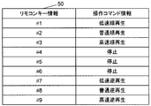
- the operation correspondence in which the key information of the remote controller used in the display device 900 together with the operation related information from the controlled devices X1 to Xn is associated with the operation command information of each controlled device X1 to Xn.
- Information 50 is transmitted.
- the display device 900 receives operation correspondence information 50 describing the correspondence between remote control key numbers used in the controlled devices X1 to Xn and the operation command information from the controlled devices X1 to Xn. get.
- the operation correspondence information 50 of FIG. 7 the first menu of the remote control key information is represented by “# 1” in FIG. 7, the second menu is represented by “# 2”, and so on.
- the display device 900 stores the operation correspondence information 50 in a storage unit (not shown).
- the display device 900 associates the key number of the remote controller used by the display device 900 with the menu number of the menu page 51 based on the stored operation correspondence information 50.
- the display device 900 causes the display unit 925 to display a remote control screen corresponding to each of the controlled devices X1 to Xn based on a request from the user.
- the display device 900 controls each of the controlled devices X1 to Xn when the user operates the remote controller. That is, the first menu on the menu page 51 is associated with the “low-speed playback” operation command, and “low-speed playback” can be executed by operating the first menu from the remote controller.
- FIG. 1 the first menu on the menu page 51 is associated with the “low-speed playback” operation command, and “low-speed playback” can be executed by operating the first menu from the remote controller.
- the first menu is represented as “# 1”
- the second menu is represented as “# 2”
- the display device 900 displays “normal playback” for the second menu, “fast playback” for the third menu, “stop” for the fourth to sixth menus, and “stop” for the seventh menu.
- “Low-speed reverse reproduction”, “No. 8 menu” corresponds to “Normal reverse reproduction”, and No. 9 menu corresponds to “High-speed reverse reproduction”.
- the function of the controlled device can be controlled by the user operating the remote control key number.
- the menu generation unit 924 In creating the menu of the menu page 51, not only the menu generation unit 924 generates, but also screen information acquired from an external server or a controlled device may be used. For example, a menu screen described in HTML from an external server, a menu screen provided in GIF, JPEG, or a bitmap image format may be acquired and used.
- the display device 900 has the menu number existing in the newly generated menu page 51 and the key number of the remote control used in the display device 900. And correspond. Therefore, the controlled devices X1 to Xn can be operated without knowing the codes of the remote control keys of the controlled devices X1 to Xn. That is, the display device 900 does not need to store operation correspondence information for all controlled devices in advance, and can reduce the storage capacity. In addition, it is possible to flexibly cope with device expansion in the device control system 100. In addition, the convenience can be improved by controlling the controlled device using the remote controller of the display device 900 that the user is familiar with.
- a predetermined priority may be provided for the operation information, and the menu generation unit 924 may dynamically generate the menu page based on this priority. For example, since the display device 900 includes the display unit 925, the menu generation unit 924 generates a menu page so that the menu page of the viewing function can be operated first, and the menu generation unit 924 performs the operation setting function during the generation process. Generate a menu page for. Thus, by dynamically generating the menu page according to the function of the control device, it is possible to facilitate the user's operation and improve the operation efficiency.
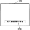
- the display device 900 can also include an operation history information storage unit 9261 that stores URL selection information in the menu page operated by the page operation unit 926 as operation history information.
- the menu generation unit 924 may assign a high priority to URL information with a high selection frequency based on the operation history information, and dynamically generate menu pages displayed in order from the URL information with the high priority. .
- the menu items (URL destinations) that are frequently operated by the user can be generated with priority and displayed, and the operation efficiency can be improved and the operation can be facilitated.
- the menu generation unit 924 displays the menu size, the character size, and the number of menu lists according to the predetermined display size.
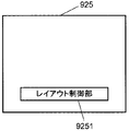
- the layout control unit 9251 deletes old menu items or deletes menu items with few operations according to the number of display items based on the number of selections and information on the selection date / time in the operation history information storage unit. It may be. Further, the layout control unit 9251 may change the menu item display mode according to the number of displays instead of deleting the menu items. For example, a new “other” item may be generated, and a menu item with a small number of selections may be included in the “other” item. Further, the display size of the menu page and the character size of the menu item may be changed according to the screen size of the display device. In this way, a menu page having a high operation frequency or a high possibility of being operated can be dynamically generated for the user, and it is easy to view, improve the operation efficiency of the user, and facilitate the operation.
- the display device 900 is a TV
- a display device including a communication unit 921, an information acquisition unit 922, an information classification unit 923, a menu generation unit 924, and a page operation unit 926 is provided in a device having a display function. It may be. For example, it can be applied to a mobile phone, a remote controller with a display function, a home information panel, a personal computer, and the like. Also by this, it is possible to perform menu display that can improve the operation efficiency of the user and facilitate the operation.
- the information classification unit creates a plurality of function groups based on the operation information of the operation related information, and the plurality of function groups into which the menu generation unit is classified.
- a menu page can be generated for each.
- the menu page is displayed on the display unit, and the user can operate with the page operation unit.
- the user can operate the controlled device from the target function group. For example, when it is desired to view a camera image on a controlled device, only the controlled device having the viewing function can be operated from the menu page by operating the menu page of the function group related to the viewing function. In this way, the operation burden on the user is reduced and the operation time is shortened, so that the controlled device can be easily operated.
- the operation information is classified into a viewing function group related to the viewing function and an operation setting function group related to the operation setting function.
- the menu generation unit can generate a menu page for each of the viewing function group related to the viewing function and the operation setting function group related to the operation setting function. Therefore, the user can operate the controlled device having the target function from the menu page only by selecting the viewing function group and the operation setting function group, and the operation time can be shortened.
- the information acquired from the controlled device can be used effectively, and the operation efficiency of the user can be improved.
- URL information based on a predetermined priority can be preferentially stored and displayed.
- the display device includes a display unit, when two functions are described in the URL destination, URL information related to the viewing function can be preferentially stored, which is close to the function possessed by the display device.
- Menu pages can be generated from things. As a result, the operation efficiency when the user operates can be improved.
- the display size of the menu page and the character size of the menu item can be changed according to the screen size of the display device, and the menu page can be displayed easily for the user.
- the remote controller screen based on the operation correspondence information can be operated, and the controlled device can be operated by operating the remote controller screen without knowing the key information of the remote controller of the controlled device. Can be controlled.
- the present invention can provide a display device that can easily operate a plurality of controlled devices connected to a network.
- grouped menu pages can be dynamically generated and operated based on the function of the operation related information of each controlled device connected to the network.
- the present invention is useful for a display device, a device control system, and the like that can easily operate the controlled device by reducing the operation time for the user and shortening the operation time.
Landscapes
- Engineering & Computer Science (AREA)
- Automation & Control Theory (AREA)
- Signal Processing (AREA)
- Computer Networks & Wireless Communication (AREA)
- General Physics & Mathematics (AREA)
- Physics & Mathematics (AREA)
- Computer Security & Cryptography (AREA)
- Theoretical Computer Science (AREA)
- Human Computer Interaction (AREA)
- Computer Hardware Design (AREA)
- Software Systems (AREA)
- General Engineering & Computer Science (AREA)
- Selective Calling Equipment (AREA)
Abstract
表示装置は、ネットワークに接続された複数の被制御機器の操作を容易に行える。表示装置は、ネットワークに接続されている被制御機器X1~Xnとの通信を行う通信部と、通信部を介して被制御機器X1~Xnから操作関連情報を取得する情報取得部と、操作関連情報に含まれる操作情報に基づいてURL情報を複数の機能グループに分類する情報分類部と、機能グループごとにメニューページを生成するメニュー生成部と、メニュー生成部によって生成されたメニューページを表示する表示部と、メニューページを操作するページ操作部とを備えている。
Description
本発明は、被制御機器とネットワーク接続された表示装置に関する。
近年、ネットワークを介して制御される家電機器(以下、「被制御機器」と記す)を利用することができるようになった。このため、ネットワークに接続された複数の被制御機器を制御するための表示装置が提案されている。
この表示装置は、ネットワークに接続して送受信を行う通信部と、情報取得部と、操作画面を表示する表示部と、表示部に表示された操作画面を操作する操作部とを備えている。情報取得部は、ネットワークに接続された被制御機器を検出し、検出した被制御機器の機器ID情報、商品カテゴリ情報、URL(Uniform Resource Locator)情報を取得する。情報取得部は、このURL情報で特定されるURL先から被制御機器を操作するための操作画面を取得する。
このような構成により、表示装置は、表示部に商品カテゴリごとに被制御機器一覧を表示し、この一覧からユーザによって選択された被制御機器を操作するための操作画面をさらにURL先から取得し、表示部に表示している。そして、この操作画面を使ってユーザは被制御機器を操作する。このような表示装置は、例えば、特許文献1に開示されている。
この様な従来の表示装置を用いてユーザが被制御機器を操作する場合、まず、ユーザは表示装置に表示されている商品カテゴリごとの被制御機器一覧から対象とする被制御機器を選択する。次に、表示装置は、ユーザによって選択された被制御機器のURL情報を表示する。そして、表示装置は、ユーザが指定したURL先にある操作画面を取得し、表示する。すなわち、ユーザは、URL先から取得された操作画面を確認した後で、初めて操作できる機能内容(視聴/動作設定)を把握することができる。このため、例えば、ユーザが、単にあるカメラの映像を見たい場合であっても、商品カテゴリ一覧から目的とする被制御機器を探す。そうしてユーザはその都度、被制御機器のURL先から操作画面をダウンロードして視聴できるか否かを確認する作業が必要である。そのため、ユーザにとって操作負担が大きく、操作時間がかかり、被制御機器の操作が容易でないといった課題がある。
特開2003-309884号公報
本発明は、ネットワークに接続された複数の被制御機器の操作を容易に行うことを可能とする表示装置を提供する。
表示装置は、被制御機器とネットワーク接続された表示装置であって、被制御機器から操作情報と操作情報に対応するURL情報とを含む操作関連情報を取得する情報取得部と、操作情報に基づいてURL情報を複数の機能グループに分類する情報分類部と、機能グループごとに被制御機器を選択するためのメニューページを生成するメニュー生成部と、メニューページを表示する表示部と、メニューページを操作することによって対応するURL情報にアクセスするページ操作部と、を備える。
27 通信部
28 操作関連情報記憶部
29 ページ処理部
30 操作関連情報
40 基本メニューページ
41 「設定する」メニュー
42 「見る」メニュー
43 「設定する」メニューページ
44 「見る」メニューページ
45 操作画面ページ
48 操作画面ページ
49 映像表示領域
50 操作対応情報
51 メニュー
100 機器制御システム
200 ホーム
300 ネットワーク
400 第1のカメラ
500 第2のカメラ
600 ドアホン
700 エアコン
800 照明機器
900 表示装置
921 通信部
922 情報取得部
923 情報分類部
924 メニュー生成部
925 表示部
926 ページ操作部
9251 レイアウト制御部
9261 操作履歴情報記憶部
28 操作関連情報記憶部
29 ページ処理部
30 操作関連情報
40 基本メニューページ
41 「設定する」メニュー
42 「見る」メニュー
43 「設定する」メニューページ
44 「見る」メニューページ
45 操作画面ページ
48 操作画面ページ
49 映像表示領域
50 操作対応情報
51 メニュー
100 機器制御システム
200 ホーム
300 ネットワーク
400 第1のカメラ
500 第2のカメラ
600 ドアホン
700 エアコン
800 照明機器
900 表示装置
921 通信部
922 情報取得部
923 情報分類部
924 メニュー生成部
925 表示部
926 ページ操作部
9251 レイアウト制御部
9261 操作履歴情報記憶部
以下、本発明の実施の形態について図面を用いて詳細に説明する。
(実施の形態1)
まず、図1から図3を参照しながら、本発明の実施の形態1における機器制御システム100について説明する。図1は本実施の形態における機器制御システム100の全体構成を示すブロック図である。図2は実施の形態1におけるUPnP仕様の拡張領域へ操作関連情報を記述した例を示す図である。図3は実施の形態1における制御機器と被制御機器の構成を示すブロック図である。
まず、図1から図3を参照しながら、本発明の実施の形態1における機器制御システム100について説明する。図1は本実施の形態における機器制御システム100の全体構成を示すブロック図である。図2は実施の形態1におけるUPnP仕様の拡張領域へ操作関連情報を記述した例を示す図である。図3は実施の形態1における制御機器と被制御機器の構成を示すブロック図である。
図1に示すように、機器制御システム100には、被制御機器と、この被制御機器を制御する制御機器を備えている。例えば、ホーム200内のネットワーク300には、被制御機器として、例えば、第1のカメラ400、第2のカメラ500、ドアホン600、エアコン700および照明機器800と、制御機器の機能を有するテレビ受像機(以下、「TV」と記す)などの表示装置900が接続されている。
制御機器と被制御機器との機器間では、例えば、UPnP(Universal Plug and Play)の仕組みを利用してメッセージのやりとりが実行される。このとき、制御機器および被制御機器は、TCP/IP(Transmission Control Protocol/Internet Protocol)で通信を行う。また、制御機器および被制御機器は、ネットワーク300に接続されると、まず、IPアドレスを取得した後、接続機器を検出するためのコマンドをマルチキャストし、ネットワーク300上の各機器に接続されたことを通知する。すなわち、制御機器および被制御機器は、ネットワーク300に接続されている全ての機器に対して新たな機器が接続されたことやその機能の内容をマルチキャストで通知する。その後も制御機器および被制御機器は、一定時間ごとに自らの存在をネットワーク300に通知する。このようにして、制御機器は被制御機器からのメッセージを受け取ると共に記憶し、その記憶しているリストを基に被制御機器を制御することが可能となる。また、制御機器は、一定時間ごとにネットワーク300に接続されている機器の接続状況を確認して、リストを最新の状況に更新することが可能である。
次に、制御機器は被制御機器のサービスを知るために、それぞれの機器がどの商品カテゴリで、どのような機能を持っているかといった機器情報やサービス情報を記述(XMLベース)したメッセージを被制御機器とやりとりする。このやりとりには、ハイパーテキスト(HTTPプロトコル)が利用される。
上述のやりとりでは、被制御機器の操作関連情報は、UPnP仕様の拡張領域を使って制御機器に渡される。例えば、UPnPのデバイス情報であるDDD(Device Description Document)の拡張領域に、図2に示すように、被制御機器の操作関連情報30が記述される。操作関連情報30としては、商品カテゴリ情報、操作情報、操作情報に対応付けられたURL情報が記述されている。このようにして、制御機器は、カメラなどの商品カテゴリ情報、MonitorやOperateなどの操作機能を示す操作情報、その操作機能の操作画面の取得先を示すURL情報などの操作関連情報を知ることができる。なお、制御機器と被制御機器との間では、後述するように、あらかじめ取り決められた仕様に従って、メッセージがやりとりされる。
このように、制御機器は、被制御機器の操作関連情報30を使って被制御機器固有の動作設定や、被制御機器固有の機能を利用することができる。
第1のカメラ400および第2のカメラ500は、カメラで被写体を撮影することができる。第1のカメラ400および第2のカメラ500は、「撮影機能」で撮影して得た映像を、ネットワーク300を介して表示装置900に出力することができる。
ドアホン600は、玄関などに設置され、訪問者との会話を行うことができる。ドアホン600は、さらにカメラを備え、このカメラによって訪問者を撮影する。このように、ドアホン600は、「通話機能」および「撮影機能」を有している。ドアホン600は、この「通話機能」および「撮影機能」を使って得た映像および音声を、ネットワーク300を介して、表示装置900に出力することができる。
エアコン700は、設定機能を使って部屋の温度や湿度を調整することができる。例えば、エアコン700は、「冷房」、「暖房」、「除湿」、「送風」などの機能を持ち、専用のリモートコントローラ(以下、「リモコン」と記す)などで操作される。なお、エアコン700は、表示装置900からネットワーク300を介しても操作される。
照明機器800は、明るさの調整機能を使って部屋の明るさを調整することができる。
このような構成により、機器制御システム100は、表示装置900から、第1のカメラ400、第2のカメラ500、ドアホン600、エアコン700および照明機器800をネットワーク300を介して制御することができる。
すなわち、表示装置900は、ネットワーク300に被制御機器が接続されると、各被制御機器から機器ID情報、商品カテゴリ情報、操作情報、URL情報などの操作関連情報を取得する。そうして、表示装置900は、この操作関連情報に含まれる操作情報(機能)を特定した後で対応するURL情報から、URL先にある操作画面を取得し、この操作画面に基づいて対応する被制御機器を操作することができるようになる。
ところで、被制御機器を制御するときの統一的な制御用コマンドとして、例えば、ECHONET(Energy Conservation and HOmecare NETwork)仕様に準拠した定義情報などを使用することもできる。このようにして、あらかじめ被制御機器の情報を知ることなく、制御を行うことが可能となる。なお、被制御機器は、ECHONET仕様に限定されず、公知の相互接続仕様に準拠し、統一的な制御を行うことができるものであればよい。相互接続仕様は、例えば、HAVi(Home Audio/Video Interoperavility)、HBS(Home Bus System)、IEEE1394シリアルバスなどがあってもよい。
ECHONETで規定された相互接続仕様を利用した場合には、カテゴリ(グループ)として「センサー関連機器」、「住宅・設備関連機器」、「健康関連機器」、「管理・操作関連機器」などがある。
上記のカテゴリの下には、それぞれに属する被制御機器が定義されている。例えば、「空調関連機器」であれば、「家庭用エアコン」、「冷風機」、「扇風機」、「換気扇」、「空気清浄機」などの機器がクラスとして定義されている。
ECHONET仕様に準拠した被制御機器では、上記したカテゴリとクラスの識別コードを内蔵することが義務付けられており、ネットワーク300を通じて各被制御機器から直接にカテゴリコードとクラスコードを読み出すことができるようになっている。
さらに、クラスはEPC(エコーネットプロパティコード)と呼ばれる属性識別子を持っており、各被制御機器の属性を表現する識別コードが割り当てられている。また、各EPCにはEDT(エコーネットプロパティ値データ)と呼ばれる属性値が定義されており、一般的には、EPCごとに独自のEDTが定義されている。
例えば、「家庭用エアコン」というクラスには、「運転モード」というEPCを持っており、このEPCには、「冷房」、「暖房」、「除湿」、「送風」、「自動」というEDTが定義されている。
このように、制御機器は、各被制御機器の識別情報、操作関連情報を取得し、統一して各被制御機器を制御するための定義情報を取得し、制御することができる。
次に、制御機器としての表示装置900は、図3に示すように、通信部921、情報取得部922、情報分類部923、メニュー生成部924、表示部925およびページ操作部926を備えている。
通信部921は、ネットワーク300に接続されている被制御機器X1~Xnとの通信を行う。被制御機器X1~Xnはそれぞれ、例えば、図1における第1のカメラ400、第2のカメラ500、ドアホン600、エアコン700、照明機器800の何れかである。情報取得部922は、通信部921を介して被制御機器X1~Xnから操作関連情報を取得する。なお、ネットワーク300に接続される被制御機器X1~Xnは、変更される場合もある。その接続状況に応じて、情報取得部922は、所定の期間ごとにネットワーク300に接続される被制御機器X1~Xnの接続状況を確認する。そうして、情報取得部922はネットワーク300に接続されている最新の被制御機器X1~Xnそれぞれの識別情報、操作情報および操作情報に対応するURL情報を含む操作関連情報を取得し、すでに取得済みの操作関連情報を更新する。
情報分類部923は、情報取得部922で取得された被制御機器X1~Xそれぞれの操作関連情報に含まれる操作情報に基づいて、URL情報を複数の機能グループに分類する。なお、情報分類部923は、操作関連情報が更新された場合には、更新された操作関連情報に基づいて、再度、操作関連情報を複数の機能グループに再分類する。
メニュー生成部924は、情報分類部923によって分類された機能グループごとにメニューページを動的に生成する。なお、メニュー生成部924は、情報分類部923で機能グループが再分類された場合、再分類された機能グループに応じて、メニューページを動的に生成する。メニュー生成部924によるメニューページ生成の詳細については後述する。
表示部925は、メニュー生成部924によって生成されたメニューページを表示する。
ページ操作部926は、表示部925に表示するメニューページやページ処理部29から送信されるURL画面を操作する。
一方、被制御機器X1~Xnはそれぞれ、通信部27と、操作関連情報記憶部28と、ページ処理部29とを備えている。
通信部27は、ネットワーク300に接続されている表示装置900との通信を行う。
操作関連情報記憶部28は、機器識別情報、操作関連情報などを記憶している。すなわち、操作関連情報記憶部28は、機器ID情報、商品カテゴリ情報、操作情報、URL情報などの定義情報などを記憶保持している。図4は、記憶される情報の一例である。
ページ処理部29は、表示装置900からURL情報に基づく操作画面ページの表示要求を受け取ると、URL情報で特定される操作画面ページ(例えば、HTML(Hyper Text Markup Language)記述されたページ)を、通信部27を介して送付する。また、被制御機器X1~Xnは、表示装置900から操作命令を受け取ると、対応する操作命令を実行する。
被制御機器X1~Xnは、それぞれ固有の機能を持ち、この固有の機能に対応する操作関連情報を持っている。例えば、図4に示すように、被制御機器X1~Xnは、商品カテゴリ情報、操作情報と、操作情報に係るURL情報を有した操作関連情報30を記憶保持している。
また、被制御機器X1~Xnは、表示装置900から操作関連情報30の要求があると、操作関連情報30として、操作情報および操作情報に係るURL情報に加えて、機器ID情報と、商品カテゴリ情報などの定義情報などを表示装置900に応答する。この応答には、UPnP仕様の拡張領域が利用される。
次に、図5を用いて、メニュー生成部924のメニューページの生成について説明する。図5は、実施の形態1の表示装置900におけるメニュー生成例を示す遷移図である。ここでは、情報分類部923が、操作関連情報30に含まれる操作情報から視聴機能(Monitor)と動作設定機能(Operate)を抽出する。そして視聴機能に係る視聴機能グループと、動作設定機能に係る動作設定機能グループとにURL情報をグループ化して分類する場合について説明する。
図5に示すように、メニュー生成部924は、まず、ユーザに機能グループの選択をさせるための基本メニューページ40を生成する。この基本メニューページ40を見ることで、ユーザは目的とする機能の機器のみを確認することができる。この基本メニューページ40としては、例えば、上記した情報分類部923によってグループ化された機能グループに応じて、ユーザに動作設定機能を選択させるための「設定する」メニュー41と、ユーザに視聴機能を選択させるための「見る」メニュー42とを作成する。この「見る」メニュー42は上述の視聴機能に係る視聴機能グループの一例である。この「設定する」メニュー41は上述の動作設定機能に係る動作設定機能グループの一例である。
次に、メニュー生成部924は、ユーザによって「設定する」メニュー41が選択されたときの「設定する」メニューページ43として、ネットワーク300に接続されている被制御機器X1~Xnの中で動作設定機能を有する機器の一覧メニューを作成する。同様に、メニュー生成部924は、ユーザによって「見る」メニュー42が選択されたときの「見る」メニューページ44として、ネットワーク300に接続されている被制御機器X1~Xnの中で視聴機能を有する機器の一覧メニューを作成する。
なお、ドアホン600は、カメラで撮影した映像や通話機能の音などの視聴機能と、カメラの感度調整や音量設定などの動作設定機能の両方を有する。そのため、情報分類部923は、ドアホン600を視聴機能に係る視聴機能グループと、動作設定機能に係る動作設定機能グループの両方に分類する。このようにして、メニュー生成部924は、「設定する」メニューページ43、「見る」メニューページ44の両方にドアホン600の選択が可能なメニューを生成する。
次に、メニュー生成部924は、「設定する」メニューページ43、「見る」メニューページ44で選択された被制御機器X1~Xnの機能に応じて、表示部925の一部に表示するための操作画面ページを生成する。「設定する」メニューページ43で、例えば、ユーザによって「エアコン」メニューが選択されると、通信部921を介して「エアコン」項目に対応付けられたURL情報はエアコン700の通信部27へ送信される。そしてエアコン700のページ処理部29から動作設定機能に係る操作画面ページ45を取得し、表示部925の一部に動作設定機能に係る操作画面ページ45が表示される。この操作画面ページ45には、動作設定機能を操作するために、「温度」メニュー46a、「風量」メニュー46b、「上げる」メニュー47a、「下げる」メニュー47bメニューが設けられている。ユーザは、「温度」メニュー46aに対して「上げる」メニュー47aと「下げる」メニュー47bが連動して操作できる。同様に、ユーザは、「風量」メニュー46bに対して「上げる」メニュー47aと「下げる」メニュー47bが連動して操作できるようになっている。このようにして、エアコン700の温度設定や、風量設定の操作がページ操作部926から可能となる。
同様に、「見る」メニューページ44で、例えば、ユーザによって上から二番目の「カメラ」メニューが選択されると、表示部925の一部に第2のカメラ500のページ処理部29から取得した視聴機能に係る操作画面ページ48が表示される。この操作画面ページ48には、第2のカメラ500の映像が表示される映像表示領域49が設けられ、映像表示領域内に第2のカメラ500の映像を表示することが可能となる。
このように、情報分類部923が操作関連情報30に含まれる操作情報に基づいて、URL情報を視聴機能に係る視聴機能グループと、動作設定機能に係る動作設定機能グループとに分類する。そしてメニュー生成部924が機能グループごとに操作情報に基づいた「設定する」メニューページ43、「見る」メニューページ44を動的に生成することができる。そして、表示部925にこの「設定する」メニューページ43、「見る」メニューページ44が表示されて、ユーザは機器をページ操作部926で操作することができる。このようにして、ユーザは、目的とする機能を直接に操作することが可能となる。すなわち、被制御機器である第2のカメラ500が撮影した映像を見たい場合には、視聴機能に係る機能グループの「見る」メニューページ44の操作画面を操作して映像を見ることができる。このように、ユーザにとって操作負担が小さく、操作時間が短縮されるため、ユーザは被制御機器を容易にかつ直感的に操作することができる。
次に、図6を用いて、制御機器である表示装置900による被制御機器X1~Xnの制御シーケンスを説明する。図6は、実施の形態1における機器制御システム100の制御シーケンスを説明するための図である。
図6において、表示装置900は、新たな被制御機器がネットワーク300に接続されたことを検出すると(S1100)、被制御機器に操作関連情報を要求する(S1102)。このとき、被制御機器は、操作関連情報を操作関連情報記憶部28から読み出し(S1104)、表示装置900に操作関連情報を応答する(S1106)。
なお、S1100~S1106は、ネットワーク300に新たに被制御機器が接続されるごとに実行される。すなわち、表示装置900は、所定の期間ごとにネットワーク300における被制御機器X1~Xnの接続状況を確認し、ネットワーク300に接続されている最新の被制御機器X1~Xnの操作関連情報を取得する。表示装置900は、ネットワーク300に接続される被制御機器X1~Xnが変更された場合には、その接続状況に応じて、被制御機器X1~Xnそれぞれから取得した操作関連情報を更新する。
次に、表示装置900は、操作関連情報に含まれる操作情報を機能ごとにグループ化する(S1108)。例えば、図2の操作関連情報30から得られる視聴機能(Monitor)と動作設定機能(Operate)を抽出し、視聴機能に係る視聴機能グループと、動作設定機能に係る動作設定機能グループとに分けて分類する。この分類処理は、被制御機器X1~Xnの操作関連情報を新たに取得する度または表示装置900の電源オン時などに行われる。なお、情報取得部922によって操作関連情報の取得情報が更新された場合には、表示装置900は、取得された操作関連情報に基づいて、複数の機能グループに再分類する。
次に、表示装置900は、メニュー生成部924により、機能グループごとに、メニューページを動的に生成する(S1110)。まず、表示装置900は、基本メニューページ40として、ユーザに動作設定機能を選択させるための「設定する」メニュー41と、ユーザに視聴機能を選択させるための「見る」メニュー42とを作成する。なお、メニュー生成部924は、機能グループの再分類にあわせて、メニューページを動的に生成する。このようにして、ユーザは、最新の接続状況を確認でき、目的とする機能の操作が可能な機器のみをメニューページで確認することができる。
次に、メニュー生成部924は、ユーザによって「設定する」メニュー41が選択されたときの「設定する」メニューページ43として、ネットワーク300に接続されている被制御機器X1~Xnの中で動作設定機能を有する機器の一覧メニューを作成する。また、メニュー生成部924は、ユーザによって「見る」メニュー42が選択されたときの「見る」メニューページ44として、ネットワーク300に接続されている被制御機器X1~Xnの中で視聴機能を有する機器の一覧メニューを作成する。
さらに、メニュー生成部924は、「設定する」メニューページ43、「見る」メニューページ44で選択された被制御機器X1~Xnの機能に応じて、表示部925の一部に表示するための操作画面ページ45、48を生成する。このように、表示装置900がTVである場合には、ユーザは番組を視聴しながら、被制御機器X1~Xnを操作するので、表示部925の一部に表示するのが好ましい。
次に、表示装置900は、ユーザからの操作に応じて、基本メニューページ40、「設定する」メニューページ43、「見る」メニューページ44、または操作画面ページ45、48のいずれかを表示部925の一部に表示する(S1112)。
ユーザは、ページ操作部926により、この表示部925に表示されたメニューページに従って被制御機器X1~Xnの操作画面ページ上で操作入力を行う(S1114)。
この操作入力により、表示装置900は操作指令を被制御機器X1~Xnに伝える(S1116)。被制御機器X1~Xnは、操作指令に従って設定された機能を実行する(S1118)。
以上述べたように、本発明の実施の形態1における機器制御システム100によれば、表示装置900は、操作関連情報30の操作情報に基づいて、操作情報を視聴機能に係る視聴機能グループと、動作設定機能に係る動作設定機能グループとに分ける。そして機能グループごとに操作情報に基づいた「設定する」メニューページ43、「見る」メニューページ44をネットワーク300に接続されている被制御機器X1~Xnの接続状況に応じて動的に生成することができる。さらに、表示部925にこの「設定する」メニューページ43、「見る」メニューページ44を表示すると共に、ページ操作部926で操作することができる。このようにして、ユーザは、機能グループを選択し、目的とする機能を直接に操作することが可能となる。例えば、被制御機器である第2のカメラ500で撮影した映像が見たい場合には、視聴機能に係る機能グループの「見る」メニューページ44を操作することで、第2のカメラ500の映像を直接に表示部925に表示させることができる。このように、ユーザにとって操作負担が小さく、操作時間が短縮されるため、被制御機器を容易に操作することができる。この結果として、ネットワーク300に接続された複数の被制御機器X1~Xnの操作を容易に行うことを可能とする表示装置900を提供することができる。
(実施の形態2)
次に、図3と図7から図10を用いて、本発明の実施の形態2における機器制御システム100での表示装置900の他の実施例について説明する。図1、図2、図4、図5、図6は実施の形態2でも共通であるので、これらの説明を省略する。ここで、本発明の実施の形態2における表示装置900と被制御機器の構成は操作関連情報記憶部28に後述する操作対応情報をさらに記憶する機能を有する以外は実施の形態1での機器制御システム100と同じである。図7は実施の形態2における被制御機器の操作対応情報の構成を示す図であり、図8は実施の形態2の表示装置900におけるメニュー配置と操作コマンドとの対応を示す関係図である。
次に、図3と図7から図10を用いて、本発明の実施の形態2における機器制御システム100での表示装置900の他の実施例について説明する。図1、図2、図4、図5、図6は実施の形態2でも共通であるので、これらの説明を省略する。ここで、本発明の実施の形態2における表示装置900と被制御機器の構成は操作関連情報記憶部28に後述する操作対応情報をさらに記憶する機能を有する以外は実施の形態1での機器制御システム100と同じである。図7は実施の形態2における被制御機器の操作対応情報の構成を示す図であり、図8は実施の形態2の表示装置900におけるメニュー配置と操作コマンドとの対応を示す関係図である。
本発明の実施の形態2では、被制御機器X1~Xnから操作関連情報と共に表示装置900で利用されるリモコンのキー情報と各被制御機器X1~Xnの操作コマンド情報とを対応させた操作対応情報50が送信される。
図7に示すように、表示装置900は、被制御機器X1~Xnから、被制御機器X1~Xnで使用されているリモコンキー番号と操作コマンド情報との対応関係を記述した操作対応情報50を取得する。図7の操作対応情報50では、リモコンキー情報の1番メニューは図7で「#1」と表記し、2番メニューは「#2」と表記し、以下同様に表記している。
図8に示すように、表示装置900は、この操作対応情報50を記憶部(図示せず)に記憶する。表示装置900は、記憶した操作対応情報50に基づいて、表示装置900が利用しているリモコンのキー番号とメニューページ51のメニュー番号と対応させる。表示装置900は、ユーザからの要求に基づいて被制御機器X1~Xnそれぞれに対応するリモコン画面を表示部925に表示させる。そして表示装置900はリモコンをユーザが操作することによって被制御機器X1~Xnそれぞれを制御する。すなわち、メニューページ51の1番メニューには、操作コマンドである「低速順再生」を対応させ、この1番メニューをリモコンから操作することで「低速順再生」を実行することができる。なお図8において、1番メニューは「#1」と表記し、2番メニューは「#2」と表記し、以下同様に表記している。以下、同様に、表示装置900は、2番メニューには「普通順再生」、3番メニューには「高速順再生」、4番~6番メニューには「停止」、7番メニューには「低速逆再生」、8番メニューには「普通逆再生」、9番メニューには「高速逆再生」を対応させる。それぞれリモコンキー番号をユーザが操作することで、被制御機器の機能を制御することができる。なお、メニューページ51のメニューの作成において、メニュー生成部924が生成するだけでなく、外部サーバあるいは被制御機器から取得した画面情報を利用してもよい。例えば、外部サーバからHTML記述されているメニュー画面や、GIFやJPEGやビットマップ画像フォーマットで提供されるメニュー画面などを取得して利用するようにしてもよい。
以上述べたように、本発明の実施の形態2における機器制御システム100によれば、表示装置900は、新たに生成したメニューページ51に存在するメニューの番号と表示装置900で使用するリモコンのキー番号とを対応させている。そのため被制御機器X1~Xnのリモコンキーのコードを知ることなしに、被制御機器X1~Xnの操作を行うことができる。つまり、表示装置900は被制御機器全ての操作対応情報をあらかじめ記憶する必要がなく記憶容量の削減を図ることができる。また機器制御システム100内の機器拡張に柔軟に対応することができる。また、ユーザが使い慣れた表示装置900のリモコンを使用して被制御機器を制御することによって、利便性を向上することもできる。
なお、操作情報に所定の優先度を設け、この優先度に基づいて、メニュー生成部924がメニューページを動的に生成するようにしてもよい。例えば、表示装置900は、表示部925を備えるので、先に視聴機能のメニューページを操作できるようにメニュー生成部924がメニューページを生成し、その生成処理の間に、メニュー生成部924が動作設定機能のメニューページを生成する。このように制御機器の機能にあわせて動的にメニューページを生成することにより、ユーザの操作を容易にし、操作効率を向上させることができる。
また、図9に示すように、表示装置900は、ページ操作部926で操作したメニューページ内でのURL選択情報を操作履歴情報として記憶する操作履歴情報記憶部9261を備えることも可能である。メニュー生成部924は、この操作履歴情報に基づいて選択頻度の多いURL情報に高い優先順位を付与し、この優先順位の高いURL情報から順に表示したメニューページを動的に生成するようにしてもよい。こうすると、さらに、ユーザがよく操作するメニュー項目(URL先)から優先して生成すると共に、表示することができ、操作効率を向上させ、操作を容易にすることができる。
さらに、表示装置900が所定の表示サイズの表示部925を備えている場合に、この所定の表示サイズに応じて、メニュー生成部924は、メニューの大きさや、文字の大きさ、メニューの一覧数を制御する。そして図10に示すように、メニュー生成部924が生成するメニューページの表示態様を動的に変更するレイアウト制御部9251を設けるようにしてもよい。これによれば、ユーザにとって見やすいメニューページを動的に生成することができ、ユーザの操作効率を向上させ、操作を容易にすることができる。
また、レイアウト制御部9251は、操作履歴情報記憶部の選択回数や選択日時の情報に基づいて、項目の表示数に応じて、古いメニュー項目を削除、または、操作の少ないメニュー項目を削除するようにしてもよい。また、レイアウト制御部9251は、メニュー項目の削除にかえて、表示数に応じてメニュー項目表示態様を変更するようにしてもよい。例えば、新たに「その他」項目を生成し、選択回数の少ないメニュー項目を「その他」項目に含めるようにしてもよい。また、表示装置の画面サイズに応じて、メニューページの表示サイズおよびメニュー項目の文字サイズを変更するようにしてもよい。このようにして、ユーザにとって操作頻度の多い、または、操作する可能性の高いメニューページを動的に生成することができ、見やすく、ユーザの操作効率を向上させ、操作を容易にすることができる。
なお、表示装置900をTVとしたが、通信部921、情報取得部922、情報分類部923、メニュー生成部924およびページ操作部926を備えた表示装置を、表示機能を備えた機器に備えるようにしてもよい。例えば、携帯電話、表示機能つきリモコン、宅内情報パネル、パーソナルコンピュータなどに応用することができる。これによっても、ユーザの操作効率を向上させ、操作を容易にすることができるメニュー表示を行うことができる。
以上の説明から明らかな通り、本発明の実施の形態によれば、情報分類部が操作関連情報の操作情報に基づいて複数の機能グループを作成し、メニュー生成部が分類された複数の機能グループごとにメニューページを生成することができる。そして、表示部にこのメニューページを表示すると共に、ユーザはページ操作部で操作することができる。このように、ユーザは目的とする機能グループから被制御機器を操作することが可能となる。例えば、被制御機器でカメラ映像が見たい場合には、視聴機能に係る機能グループのメニューページを操作することで、視聴機能を有する被制御機器のみをメニューページから操作することができる。このようにして、ユーザにとって操作負担が小さくなり、操作時間が短縮されるため、被制御機器を容易に操作することができる。
また、本発明の実施の形態によれば、操作情報を、視聴機能に係る視聴機能グループと、動作設定機能に係る動作設定機能グループとに分けて分類する。そしてメニュー生成部は、視聴機能に係る視聴機能グループと、動作設定機能に係る動作設定機能グループそれぞれのメニューページを生成することができる。このため、ユーザは、視聴機能グループと動作設定機能グループを選択するだけで、メニューページから目的とする機能の被制御機器を操作することが可能となり、操作時間を短縮することができる。
さらに、本発明の実施の形態によれば、被制御機器から取得する情報を有効に活用でき、ユーザの操作効率を向上させることができる。
さらに、本発明の実施の形態によれば、所定の優先度に基づくURL情報を優先的に記憶すると共に、表示することが可能となる。例えば、表示装置は表示部を備えるため、URL先に2つの機能が記述されている場合には、視聴機能に係るURL情報を優先的に記憶することができ、表示装置が保有する機能に近いものからメニューページを生成することが可能となる。その結果として、ユーザが操作する際の操作効率を向上させることができる。
さらにまた、本発明の実施の形態によれば、表示装置の画面サイズに応じて、メニューページの表示サイズおよびメニュー項目の文字サイズを変更することができ、ユーザにとって見やすいメニューページの表示が可能となる。
さらに、本構成によれば、操作対応情報に基づくリモートコントローラ画面を操作することができ、被制御機器のリモートコントローラのキー情報を知ることなしに、リモートコントローラ画面を操作することによって、被制御機器を制御することができる。
以上のごとく本発明は、ネットワークに接続された複数の被制御機器の操作を容易に行うことを可能とする表示装置を提供することができる。
本発明によれば、ネットワークに接続された各被制御機器の操作関連情報の機能に基づいてグループ化したメニューページを動的に生成して操作することができる。こうすることにより本発明は、ユーザにとって操作負担が小さく、操作時間を短縮することにより、被制御機器を容易に操作することが可能な表示装置、機器制御システムなどに有用である。
Claims (6)
- 被制御機器とネットワーク接続された表示装置であって、
前記被制御機器から、操作情報と前記操作情報に対応するURL情報とを含む操作関連情報を取得する情報取得部と、
前記操作情報に基づいて、前記URL情報を複数の機能グループに分類する情報分類部と、
前記機能グループごとに前記被制御機器を選択するためのメニューページを生成するメニュー生成部と、
前記メニューページを表示する表示部と、
前記メニューページを操作することによって、対応するURL情報にアクセスするページ操作部と、
を備える表示装置。 - 前記機能グループは、
視聴機能に係る視聴機能グループと、
動作設定機能に係る動作設定機能グループ
を含む請求項1に記載の表示装置。 - 前記操作情報は優先度を有し、
前記メニュー生成部は、前記優先度に基づいて前記メニューページを生成する
請求項1に記載の表示装置。 - 前記ページ操作部でアクセスしたURL情報を操作履歴情報として記憶する操作履歴情報記憶部をさらに備え、
前記メニュー生成部は、優先度に基づいて前記操作履歴情報記憶部に記憶した前記操作履歴情報に基づいて前記メニューページを生成する
請求項3に記載の表示装置。 - 前記操作履歴情報に基づいて、前記メニューページのメニュー項目表示態様を変更させるレイアウト制御部をさらに備える
請求項4に記載の表示装置。 - 前記情報取得部は、前記被制御機器のリモートコントローラのキー情報と操作コマンド情報とを対応付けた操作対応情報をさらに取得し、
前記表示部は前記操作対応情報に基づいて前記メニュー生成部が生成したリモートコントローラ画面を表示し、
前記リモートコントローラ画面のキーに対応する操作コマンド情報を用いて前記被制御機器を操作する
請求項1に記載の表示装置。
Priority Applications (2)
| Application Number | Priority Date | Filing Date | Title |
|---|---|---|---|
| EP09705840.8A EP2117255B1 (en) | 2008-01-31 | 2009-01-29 | Display device |
| US12/597,000 US8745532B2 (en) | 2008-01-31 | 2009-01-29 | Display device |
Applications Claiming Priority (2)
| Application Number | Priority Date | Filing Date | Title |
|---|---|---|---|
| JP2008-020466 | 2008-01-31 | ||
| JP2008020466A JP5119953B2 (ja) | 2008-01-31 | 2008-01-31 | 表示装置 |
Publications (1)
| Publication Number | Publication Date |
|---|---|
| WO2009096183A1 true WO2009096183A1 (ja) | 2009-08-06 |
Family
ID=40912538
Family Applications (1)
| Application Number | Title | Priority Date | Filing Date |
|---|---|---|---|
| PCT/JP2009/000342 Ceased WO2009096183A1 (ja) | 2008-01-31 | 2009-01-29 | 表示装置 |
Country Status (4)
| Country | Link |
|---|---|
| US (1) | US8745532B2 (ja) |
| EP (1) | EP2117255B1 (ja) |
| JP (1) | JP5119953B2 (ja) |
| WO (1) | WO2009096183A1 (ja) |
Cited By (2)
| Publication number | Priority date | Publication date | Assignee | Title |
|---|---|---|---|---|
| WO2011061920A1 (ja) * | 2009-11-18 | 2011-05-26 | パナソニック株式会社 | 無線リモコンシステム及び無線リモコンのペアリング方法 |
| CN108694306A (zh) * | 2017-03-29 | 2018-10-23 | 三星电子株式会社 | 管理和控制外部物联网设备的方法和支持其的电子设备 |
Families Citing this family (7)
| Publication number | Priority date | Publication date | Assignee | Title |
|---|---|---|---|---|
| JP2011066850A (ja) * | 2009-09-18 | 2011-03-31 | Fujitsu Toshiba Mobile Communications Ltd | 情報通信端末 |
| WO2012008628A1 (ko) * | 2010-07-13 | 2012-01-19 | 엘지전자 주식회사 | 이동단말기 및 그 대기화면 구성방법 |
| KR101718894B1 (ko) | 2011-11-29 | 2017-03-23 | 삼성전자주식회사 | 기기 제어를 위한 유저 인터페이스 제공 시스템 및 방법 |
| JP6192907B2 (ja) * | 2012-08-06 | 2017-09-06 | 京セラ株式会社 | エネルギー管理装置、エネルギー管理システムおよびエネルギー管理方法 |
| CN104169658B (zh) | 2013-02-20 | 2017-09-19 | 松下电器(美国)知识产权公司 | 便携信息终端的控制方法和程序 |
| JP6688954B2 (ja) * | 2015-11-18 | 2020-04-28 | パナソニックIpマネジメント株式会社 | メッセージ受信装置及び画面遷移方法 |
| CN109783707A (zh) * | 2019-01-23 | 2019-05-21 | 欧普照明股份有限公司 | 一种监控系统的模式设置方法和装置 |
Citations (3)
| Publication number | Priority date | Publication date | Assignee | Title |
|---|---|---|---|---|
| JPH06233202A (ja) * | 1993-01-29 | 1994-08-19 | Pioneer Electron Corp | 音響・映像機器の選択方法 |
| JP2001344163A (ja) * | 2000-05-31 | 2001-12-14 | Matsushita Electric Ind Co Ltd | 信号処理装置、媒体および情報集合体 |
| JP2003309884A (ja) * | 2002-04-18 | 2003-10-31 | Matsushita Electric Ind Co Ltd | リモートコントロール装置および記録媒体 |
Family Cites Families (22)
| Publication number | Priority date | Publication date | Assignee | Title |
|---|---|---|---|---|
| US5396264A (en) * | 1994-01-03 | 1995-03-07 | Motorola, Inc. | Automatic menu item sequencing method |
| DE69838439T2 (de) * | 1997-06-25 | 2008-06-12 | Samsung Electronics Co., Ltd., Suwon | Verfahren und Vorrichtung zur Überwachung von Geräten in einem Hausnetzwerk |
| US6580950B1 (en) * | 2000-04-28 | 2003-06-17 | Echelon Corporation | Internet based home communications system |
| US7184024B2 (en) * | 2000-06-30 | 2007-02-27 | Nokia Corporation | Method and apparatus for mapping an input location with a displayed functional representation |
| EP1233602A4 (en) * | 2000-09-27 | 2004-09-08 | Ntt Docomo Inc | REMOTE CONTROL METHOD FOR ELECTRONIC DEVICES AND DEVICE FOR MANAGING ELECTRONIC DEVICES |
| JP4434467B2 (ja) | 2000-11-01 | 2010-03-17 | キヤノン株式会社 | ユーザインタフェース制御装置 |
| US8190695B2 (en) * | 2001-08-02 | 2012-05-29 | Sony Corporation | Remote control system and remote control method, device for performing remote control operation and control method therefor, device operable by remote control operation and control method therefor, and storage medium |
| AU2003242047A1 (en) * | 2002-06-19 | 2004-01-06 | Matsushita Electric Industrial Co., Ltd. | Server, electronic apparatus, external apparatus and information processing system using them, and electronic apparatus setting and status acquisition method |
| KR100932813B1 (ko) * | 2002-10-01 | 2009-12-21 | 엘지전자 주식회사 | 동일 유형의 홈 네트웍 기기를 위치별로 구분 및 표시하는장치 |
| AU2003246151A1 (en) * | 2003-05-30 | 2005-01-21 | Lg Electronics, Inc. | Home network system |
| KR100606760B1 (ko) * | 2003-07-07 | 2006-07-31 | 엘지전자 주식회사 | 사용자 예약에 따른 홈 네트워크 시스템 및 그 제어방법 |
| JP4073455B2 (ja) * | 2004-01-19 | 2008-04-09 | 松下電器産業株式会社 | 顧客管理方法及びそのプログラム |
| US7786891B2 (en) * | 2004-08-27 | 2010-08-31 | Embarq Holdings Company, Llc | System and method for an interactive security system for a home |
| JP4041118B2 (ja) * | 2004-11-24 | 2008-01-30 | 株式会社東芝 | ゲートウェイ装置、ネットワークシステム、通信プログラム及び通信方法 |
| CN101218790A (zh) * | 2005-07-04 | 2008-07-09 | Sk电信股份有限公司 | 家庭网络系统及其控制方法、设置家庭网络系统的住宅网关的方法以及处理家庭网络系统的事件协议的方法 |
| KR20070062094A (ko) * | 2005-12-12 | 2007-06-15 | 삼성전자주식회사 | Ui제공 장치 및 방법 |
| US7877467B2 (en) * | 2005-12-28 | 2011-01-25 | Panasonic Electric Works Co., Ltd | Network equipment system |
| US20070276691A1 (en) * | 2006-05-12 | 2007-11-29 | Ordercatcher, Llc | System and method for processing orders from a menu |
| KR100822706B1 (ko) * | 2006-12-08 | 2008-04-17 | 한국전자통신연구원 | 근거리 무선 통신을 이용한 가전기기 제어 장치 및 그 방법 |
| US8170183B2 (en) * | 2007-01-22 | 2012-05-01 | Control4 Corporation | Systems and methods for providing a message service for a site |
| US8310335B2 (en) * | 2007-09-07 | 2012-11-13 | Verizon Patent And Licensing Inc. | Network-based access and control of home automation systems |
| US7639907B2 (en) * | 2007-11-14 | 2009-12-29 | Elbex Video Ltd. | Method and apparatus for operating AC powered appliances via video interphones, two way IR drivers and remote control devices |
-
2008
- 2008-01-31 JP JP2008020466A patent/JP5119953B2/ja not_active Expired - Fee Related
-
2009
- 2009-01-29 EP EP09705840.8A patent/EP2117255B1/en not_active Not-in-force
- 2009-01-29 US US12/597,000 patent/US8745532B2/en not_active Expired - Fee Related
- 2009-01-29 WO PCT/JP2009/000342 patent/WO2009096183A1/ja not_active Ceased
Patent Citations (3)
| Publication number | Priority date | Publication date | Assignee | Title |
|---|---|---|---|---|
| JPH06233202A (ja) * | 1993-01-29 | 1994-08-19 | Pioneer Electron Corp | 音響・映像機器の選択方法 |
| JP2001344163A (ja) * | 2000-05-31 | 2001-12-14 | Matsushita Electric Ind Co Ltd | 信号処理装置、媒体および情報集合体 |
| JP2003309884A (ja) * | 2002-04-18 | 2003-10-31 | Matsushita Electric Ind Co Ltd | リモートコントロール装置および記録媒体 |
Non-Patent Citations (1)
| Title |
|---|
| See also references of EP2117255A4 * |
Cited By (4)
| Publication number | Priority date | Publication date | Assignee | Title |
|---|---|---|---|---|
| WO2011061920A1 (ja) * | 2009-11-18 | 2011-05-26 | パナソニック株式会社 | 無線リモコンシステム及び無線リモコンのペアリング方法 |
| CN108694306A (zh) * | 2017-03-29 | 2018-10-23 | 三星电子株式会社 | 管理和控制外部物联网设备的方法和支持其的电子设备 |
| CN108694306B (zh) * | 2017-03-29 | 2024-03-15 | 三星电子株式会社 | 管理和控制外部物联网设备的方法和支持其的电子设备 |
| USRE50074E1 (en) | 2017-03-29 | 2024-08-06 | Samsung Electronics Co., Ltd. | Method for managing and controlling external IoT device and electronic device supporting the same |
Also Published As
| Publication number | Publication date |
|---|---|
| EP2117255A1 (en) | 2009-11-11 |
| EP2117255A4 (en) | 2013-11-06 |
| EP2117255B1 (en) | 2015-01-21 |
| JP2009182771A (ja) | 2009-08-13 |
| US8745532B2 (en) | 2014-06-03 |
| JP5119953B2 (ja) | 2013-01-16 |
| US20100131897A1 (en) | 2010-05-27 |
Similar Documents
| Publication | Publication Date | Title |
|---|---|---|
| JP5119953B2 (ja) | 表示装置 | |
| KR101844021B1 (ko) | 메시지 전송 방법 및 장치와 컴퓨터로 읽을 수 있는 저장 매체 | |
| CN102959597B (zh) | 电话的远程控制方法和设备 | |
| CN103383128B (zh) | 多联式中央空调的集中控制系统和控制方法 | |
| KR100932813B1 (ko) | 동일 유형의 홈 네트웍 기기를 위치별로 구분 및 표시하는장치 | |
| US11711277B2 (en) | Information management method | |
| CN101115315A (zh) | 管理员装置、控制方法以及控制程序 | |
| US20080091776A1 (en) | Information processing apparatus and information processing system | |
| WO2003063475A1 (en) | Remote wireless device with epg display, intercom and emulated control buttons | |
| KR100453968B1 (ko) | 홈 네트워크 시스템의 사용자 인터페이스 제공 방법 | |
| CN108803371A (zh) | 一种电器设备的控制方法以及装置 | |
| JP5842809B2 (ja) | 制御対象機器、機器制御システム、機器制御プログラム、および機器制御方法 | |
| JP4327622B2 (ja) | 環境制御方法および環境制御装置 | |
| JP2005310022A (ja) | 機器制御システム | |
| JP2006352666A (ja) | ネットワーク家電制御システム | |
| EP3429135A1 (en) | Method and apparatus for providing a service menu in a network environment | |
| JP2005150901A (ja) | 機器登録システムおよび情報端末 | |
| JP2005217645A (ja) | リモコン端末、サーバ装置およびネットワーク対応機器 | |
| CN101166131A (zh) | 基于通用即插即用网络系统及其控制方法 | |
| JP5215697B2 (ja) | 画面表示方法 | |
| JP2005026879A (ja) | 通信装置、および電気器具 | |
| JP2006324913A (ja) | 遠隔制御データ配信装置及び遠隔制御データ配信システム | |
| JP2001274818A (ja) | ネットワーク装置 | |
| JP2015041257A (ja) | サーバ、サーバの制御方法、サーバの制御プログラム、通信システム、および情報処理装置 |
Legal Events
| Date | Code | Title | Description |
|---|---|---|---|
| WWE | Wipo information: entry into national phase |
Ref document number: 2009705840 Country of ref document: EP |
|
| 121 | Ep: the epo has been informed by wipo that ep was designated in this application |
Ref document number: 09705840 Country of ref document: EP Kind code of ref document: A1 |
|
| WWE | Wipo information: entry into national phase |
Ref document number: 12597000 Country of ref document: US |
|
| NENP | Non-entry into the national phase |
Ref country code: DE |