WO2009096512A1 - 貯湯式給湯機および貯湯式暖房給湯機 - Google Patents
貯湯式給湯機および貯湯式暖房給湯機 Download PDFInfo
- Publication number
- WO2009096512A1 WO2009096512A1 PCT/JP2009/051552 JP2009051552W WO2009096512A1 WO 2009096512 A1 WO2009096512 A1 WO 2009096512A1 JP 2009051552 W JP2009051552 W JP 2009051552W WO 2009096512 A1 WO2009096512 A1 WO 2009096512A1
- Authority
- WO
- WIPO (PCT)
- Prior art keywords
- hot water
- water storage
- storage type
- heating
- storage tank
- Prior art date
- Legal status (The legal status is an assumption and is not a legal conclusion. Google has not performed a legal analysis and makes no representation as to the accuracy of the status listed.)
- Ceased
Links
Images


Classifications
-
- F—MECHANICAL ENGINEERING; LIGHTING; HEATING; WEAPONS; BLASTING
- F24—HEATING; RANGES; VENTILATING
- F24D—DOMESTIC- OR SPACE-HEATING SYSTEMS, e.g. CENTRAL HEATING SYSTEMS; DOMESTIC HOT-WATER SUPPLY SYSTEMS; ELEMENTS OR COMPONENTS THEREFOR
- F24D11/00—Central heating systems using heat accumulated in storage masses
- F24D11/02—Central heating systems using heat accumulated in storage masses using heat pumps
- F24D11/0214—Central heating systems using heat accumulated in storage masses using heat pumps water heating system
-
- F—MECHANICAL ENGINEERING; LIGHTING; HEATING; WEAPONS; BLASTING
- F24—HEATING; RANGES; VENTILATING
- F24D—DOMESTIC- OR SPACE-HEATING SYSTEMS, e.g. CENTRAL HEATING SYSTEMS; DOMESTIC HOT-WATER SUPPLY SYSTEMS; ELEMENTS OR COMPONENTS THEREFOR
- F24D12/00—Other central heating systems
- F24D12/02—Other central heating systems having more than one heat source
-
- F—MECHANICAL ENGINEERING; LIGHTING; HEATING; WEAPONS; BLASTING
- F24—HEATING; RANGES; VENTILATING
- F24D—DOMESTIC- OR SPACE-HEATING SYSTEMS, e.g. CENTRAL HEATING SYSTEMS; DOMESTIC HOT-WATER SUPPLY SYSTEMS; ELEMENTS OR COMPONENTS THEREFOR
- F24D19/00—Details
- F24D19/10—Arrangement or mounting of control or safety devices
- F24D19/1006—Arrangement or mounting of control or safety devices for water heating systems
- F24D19/1066—Arrangement or mounting of control or safety devices for water heating systems for the combination of central heating and domestic hot water
- F24D19/1072—Arrangement or mounting of control or safety devices for water heating systems for the combination of central heating and domestic hot water the system uses a heat pump
-
- F—MECHANICAL ENGINEERING; LIGHTING; HEATING; WEAPONS; BLASTING
- F24—HEATING; RANGES; VENTILATING
- F24D—DOMESTIC- OR SPACE-HEATING SYSTEMS, e.g. CENTRAL HEATING SYSTEMS; DOMESTIC HOT-WATER SUPPLY SYSTEMS; ELEMENTS OR COMPONENTS THEREFOR
- F24D3/00—Hot-water central heating systems
- F24D3/08—Hot-water central heating systems in combination with systems for domestic hot-water supply
- F24D3/082—Hot water storage tanks specially adapted therefor
-
- F—MECHANICAL ENGINEERING; LIGHTING; HEATING; WEAPONS; BLASTING
- F24—HEATING; RANGES; VENTILATING
- F24H—FLUID HEATERS, e.g. WATER OR AIR HEATERS, HAVING HEAT-GENERATING MEANS, e.g. HEAT PUMPS, IN GENERAL
- F24H15/00—Control of fluid heaters
- F24H15/10—Control of fluid heaters characterised by the purpose of the control
- F24H15/174—Supplying heated water with desired temperature or desired range of temperature
-
- F—MECHANICAL ENGINEERING; LIGHTING; HEATING; WEAPONS; BLASTING
- F24—HEATING; RANGES; VENTILATING
- F24H—FLUID HEATERS, e.g. WATER OR AIR HEATERS, HAVING HEAT-GENERATING MEANS, e.g. HEAT PUMPS, IN GENERAL
- F24H15/00—Control of fluid heaters
- F24H15/20—Control of fluid heaters characterised by control inputs
- F24H15/212—Temperature of the water
- F24H15/215—Temperature of the water before heating
-
- F—MECHANICAL ENGINEERING; LIGHTING; HEATING; WEAPONS; BLASTING
- F24—HEATING; RANGES; VENTILATING
- F24H—FLUID HEATERS, e.g. WATER OR AIR HEATERS, HAVING HEAT-GENERATING MEANS, e.g. HEAT PUMPS, IN GENERAL
- F24H15/00—Control of fluid heaters
- F24H15/20—Control of fluid heaters characterised by control inputs
- F24H15/212—Temperature of the water
- F24H15/219—Temperature of the water after heating
-
- F—MECHANICAL ENGINEERING; LIGHTING; HEATING; WEAPONS; BLASTING
- F24—HEATING; RANGES; VENTILATING
- F24H—FLUID HEATERS, e.g. WATER OR AIR HEATERS, HAVING HEAT-GENERATING MEANS, e.g. HEAT PUMPS, IN GENERAL
- F24H15/00—Control of fluid heaters
- F24H15/20—Control of fluid heaters characterised by control inputs
- F24H15/212—Temperature of the water
- F24H15/223—Temperature of the water in the water storage tank
- F24H15/225—Temperature of the water in the water storage tank at different heights of the tank
-
- F—MECHANICAL ENGINEERING; LIGHTING; HEATING; WEAPONS; BLASTING
- F24—HEATING; RANGES; VENTILATING
- F24H—FLUID HEATERS, e.g. WATER OR AIR HEATERS, HAVING HEAT-GENERATING MEANS, e.g. HEAT PUMPS, IN GENERAL
- F24H15/00—Control of fluid heaters
- F24H15/20—Control of fluid heaters characterised by control inputs
- F24H15/227—Temperature of the refrigerant in heat pump cycles
- F24H15/231—Temperature of the refrigerant in heat pump cycles at the evaporator
-
- F—MECHANICAL ENGINEERING; LIGHTING; HEATING; WEAPONS; BLASTING
- F24—HEATING; RANGES; VENTILATING
- F24H—FLUID HEATERS, e.g. WATER OR AIR HEATERS, HAVING HEAT-GENERATING MEANS, e.g. HEAT PUMPS, IN GENERAL
- F24H15/00—Control of fluid heaters
- F24H15/20—Control of fluid heaters characterised by control inputs
- F24H15/242—Pressure
-
- F—MECHANICAL ENGINEERING; LIGHTING; HEATING; WEAPONS; BLASTING
- F24—HEATING; RANGES; VENTILATING
- F24H—FLUID HEATERS, e.g. WATER OR AIR HEATERS, HAVING HEAT-GENERATING MEANS, e.g. HEAT PUMPS, IN GENERAL
- F24H15/00—Control of fluid heaters
- F24H15/20—Control of fluid heaters characterised by control inputs
- F24H15/258—Outdoor temperature
-
- F—MECHANICAL ENGINEERING; LIGHTING; HEATING; WEAPONS; BLASTING
- F24—HEATING; RANGES; VENTILATING
- F24H—FLUID HEATERS, e.g. WATER OR AIR HEATERS, HAVING HEAT-GENERATING MEANS, e.g. HEAT PUMPS, IN GENERAL
- F24H15/00—Control of fluid heaters
- F24H15/30—Control of fluid heaters characterised by control outputs; characterised by the components to be controlled
- F24H15/305—Control of valves
- F24H15/315—Control of valves of mixing valves
-
- F—MECHANICAL ENGINEERING; LIGHTING; HEATING; WEAPONS; BLASTING
- F24—HEATING; RANGES; VENTILATING
- F24H—FLUID HEATERS, e.g. WATER OR AIR HEATERS, HAVING HEAT-GENERATING MEANS, e.g. HEAT PUMPS, IN GENERAL
- F24H15/00—Control of fluid heaters
- F24H15/30—Control of fluid heaters characterised by control outputs; characterised by the components to be controlled
- F24H15/305—Control of valves
- F24H15/32—Control of valves of switching valves
-
- F—MECHANICAL ENGINEERING; LIGHTING; HEATING; WEAPONS; BLASTING
- F24—HEATING; RANGES; VENTILATING
- F24H—FLUID HEATERS, e.g. WATER OR AIR HEATERS, HAVING HEAT-GENERATING MEANS, e.g. HEAT PUMPS, IN GENERAL
- F24H15/00—Control of fluid heaters
- F24H15/30—Control of fluid heaters characterised by control outputs; characterised by the components to be controlled
- F24H15/335—Control of pumps, e.g. on-off control
-
- F—MECHANICAL ENGINEERING; LIGHTING; HEATING; WEAPONS; BLASTING
- F24—HEATING; RANGES; VENTILATING
- F24H—FLUID HEATERS, e.g. WATER OR AIR HEATERS, HAVING HEAT-GENERATING MEANS, e.g. HEAT PUMPS, IN GENERAL
- F24H15/00—Control of fluid heaters
- F24H15/30—Control of fluid heaters characterised by control outputs; characterised by the components to be controlled
- F24H15/355—Control of heat-generating means in heaters
- F24H15/37—Control of heat-generating means in heaters of electric heaters
-
- F—MECHANICAL ENGINEERING; LIGHTING; HEATING; WEAPONS; BLASTING
- F24—HEATING; RANGES; VENTILATING
- F24H—FLUID HEATERS, e.g. WATER OR AIR HEATERS, HAVING HEAT-GENERATING MEANS, e.g. HEAT PUMPS, IN GENERAL
- F24H15/00—Control of fluid heaters
- F24H15/30—Control of fluid heaters characterised by control outputs; characterised by the components to be controlled
- F24H15/375—Control of heat pumps
- F24H15/38—Control of compressors of heat pumps
-
- F—MECHANICAL ENGINEERING; LIGHTING; HEATING; WEAPONS; BLASTING
- F24—HEATING; RANGES; VENTILATING
- F24H—FLUID HEATERS, e.g. WATER OR AIR HEATERS, HAVING HEAT-GENERATING MEANS, e.g. HEAT PUMPS, IN GENERAL
- F24H15/00—Control of fluid heaters
- F24H15/30—Control of fluid heaters characterised by control outputs; characterised by the components to be controlled
- F24H15/375—Control of heat pumps
- F24H15/385—Control of expansion valves of heat pumps
-
- F—MECHANICAL ENGINEERING; LIGHTING; HEATING; WEAPONS; BLASTING
- F28—HEAT EXCHANGE IN GENERAL
- F28D—HEAT-EXCHANGE APPARATUS, NOT PROVIDED FOR IN ANOTHER SUBCLASS, IN WHICH THE HEAT-EXCHANGE MEDIA DO NOT COME INTO DIRECT CONTACT
- F28D20/00—Heat storage plants or apparatus in general; Regenerative heat-exchange apparatus not covered by groups F28D17/00 or F28D19/00
- F28D20/0034—Heat storage plants or apparatus in general; Regenerative heat-exchange apparatus not covered by groups F28D17/00 or F28D19/00 using liquid heat storage material
- F28D20/0039—Heat storage plants or apparatus in general; Regenerative heat-exchange apparatus not covered by groups F28D17/00 or F28D19/00 using liquid heat storage material with stratification of the heat storage material
-
- F—MECHANICAL ENGINEERING; LIGHTING; HEATING; WEAPONS; BLASTING
- F28—HEAT EXCHANGE IN GENERAL
- F28D—HEAT-EXCHANGE APPARATUS, NOT PROVIDED FOR IN ANOTHER SUBCLASS, IN WHICH THE HEAT-EXCHANGE MEDIA DO NOT COME INTO DIRECT CONTACT
- F28D7/00—Heat-exchange apparatus having stationary tubular conduit assemblies for both heat-exchange media, the media being in contact with different sides of a conduit wall
- F28D7/02—Heat-exchange apparatus having stationary tubular conduit assemblies for both heat-exchange media, the media being in contact with different sides of a conduit wall the conduits being helically coiled
- F28D7/024—Heat-exchange apparatus having stationary tubular conduit assemblies for both heat-exchange media, the media being in contact with different sides of a conduit wall the conduits being helically coiled the conduits of only one medium being helically coiled tubes, the coils having a cylindrical configuration
-
- F—MECHANICAL ENGINEERING; LIGHTING; HEATING; WEAPONS; BLASTING
- F28—HEAT EXCHANGE IN GENERAL
- F28F—DETAILS OF HEAT-EXCHANGE AND HEAT-TRANSFER APPARATUS, OF GENERAL APPLICATION
- F28F1/00—Tubular elements; Assemblies of tubular elements
- F28F1/10—Tubular elements and assemblies thereof with means for increasing heat-transfer area, e.g. with fins, with projections, with recesses
- F28F1/12—Tubular elements and assemblies thereof with means for increasing heat-transfer area, e.g. with fins, with projections, with recesses the means being only outside the tubular element
- F28F1/14—Tubular elements and assemblies thereof with means for increasing heat-transfer area, e.g. with fins, with projections, with recesses the means being only outside the tubular element and extending longitudinally
- F28F1/20—Tubular elements and assemblies thereof with means for increasing heat-transfer area, e.g. with fins, with projections, with recesses the means being only outside the tubular element and extending longitudinally the means being attachable to the element
-
- F—MECHANICAL ENGINEERING; LIGHTING; HEATING; WEAPONS; BLASTING
- F28—HEAT EXCHANGE IN GENERAL
- F28F—DETAILS OF HEAT-EXCHANGE AND HEAT-TRANSFER APPARATUS, OF GENERAL APPLICATION
- F28F1/00—Tubular elements; Assemblies of tubular elements
- F28F1/10—Tubular elements and assemblies thereof with means for increasing heat-transfer area, e.g. with fins, with projections, with recesses
- F28F1/12—Tubular elements and assemblies thereof with means for increasing heat-transfer area, e.g. with fins, with projections, with recesses the means being only outside the tubular element
- F28F1/34—Tubular elements and assemblies thereof with means for increasing heat-transfer area, e.g. with fins, with projections, with recesses the means being only outside the tubular element and extending obliquely
- F28F1/36—Tubular elements and assemblies thereof with means for increasing heat-transfer area, e.g. with fins, with projections, with recesses the means being only outside the tubular element and extending obliquely the means being helically wound fins or wire spirals
-
- F—MECHANICAL ENGINEERING; LIGHTING; HEATING; WEAPONS; BLASTING
- F28—HEAT EXCHANGE IN GENERAL
- F28F—DETAILS OF HEAT-EXCHANGE AND HEAT-TRANSFER APPARATUS, OF GENERAL APPLICATION
- F28F1/00—Tubular elements; Assemblies of tubular elements
- F28F1/10—Tubular elements and assemblies thereof with means for increasing heat-transfer area, e.g. with fins, with projections, with recesses
- F28F1/40—Tubular elements and assemblies thereof with means for increasing heat-transfer area, e.g. with fins, with projections, with recesses the means being only inside the tubular element
-
- F—MECHANICAL ENGINEERING; LIGHTING; HEATING; WEAPONS; BLASTING
- F24—HEATING; RANGES; VENTILATING
- F24D—DOMESTIC- OR SPACE-HEATING SYSTEMS, e.g. CENTRAL HEATING SYSTEMS; DOMESTIC HOT-WATER SUPPLY SYSTEMS; ELEMENTS OR COMPONENTS THEREFOR
- F24D2200/00—Heat sources or energy sources
- F24D2200/06—Solid fuel fired boiler
-
- F—MECHANICAL ENGINEERING; LIGHTING; HEATING; WEAPONS; BLASTING
- F24—HEATING; RANGES; VENTILATING
- F24D—DOMESTIC- OR SPACE-HEATING SYSTEMS, e.g. CENTRAL HEATING SYSTEMS; DOMESTIC HOT-WATER SUPPLY SYSTEMS; ELEMENTS OR COMPONENTS THEREFOR
- F24D2200/00—Heat sources or energy sources
- F24D2200/08—Electric heater
-
- F—MECHANICAL ENGINEERING; LIGHTING; HEATING; WEAPONS; BLASTING
- F24—HEATING; RANGES; VENTILATING
- F24D—DOMESTIC- OR SPACE-HEATING SYSTEMS, e.g. CENTRAL HEATING SYSTEMS; DOMESTIC HOT-WATER SUPPLY SYSTEMS; ELEMENTS OR COMPONENTS THEREFOR
- F24D2200/00—Heat sources or energy sources
- F24D2200/12—Heat pump
-
- F—MECHANICAL ENGINEERING; LIGHTING; HEATING; WEAPONS; BLASTING
- F24—HEATING; RANGES; VENTILATING
- F24D—DOMESTIC- OR SPACE-HEATING SYSTEMS, e.g. CENTRAL HEATING SYSTEMS; DOMESTIC HOT-WATER SUPPLY SYSTEMS; ELEMENTS OR COMPONENTS THEREFOR
- F24D2220/00—Components of central heating installations excluding heat sources
- F24D2220/04—Sensors
- F24D2220/042—Temperature sensors
-
- F—MECHANICAL ENGINEERING; LIGHTING; HEATING; WEAPONS; BLASTING
- F24—HEATING; RANGES; VENTILATING
- F24D—DOMESTIC- OR SPACE-HEATING SYSTEMS, e.g. CENTRAL HEATING SYSTEMS; DOMESTIC HOT-WATER SUPPLY SYSTEMS; ELEMENTS OR COMPONENTS THEREFOR
- F24D2220/00—Components of central heating installations excluding heat sources
- F24D2220/20—Heat consumers
- F24D2220/2009—Radiators
-
- F—MECHANICAL ENGINEERING; LIGHTING; HEATING; WEAPONS; BLASTING
- F24—HEATING; RANGES; VENTILATING
- F24D—DOMESTIC- OR SPACE-HEATING SYSTEMS, e.g. CENTRAL HEATING SYSTEMS; DOMESTIC HOT-WATER SUPPLY SYSTEMS; ELEMENTS OR COMPONENTS THEREFOR
- F24D2220/00—Components of central heating installations excluding heat sources
- F24D2220/20—Heat consumers
- F24D2220/209—Sanitary water taps
-
- F—MECHANICAL ENGINEERING; LIGHTING; HEATING; WEAPONS; BLASTING
- F24—HEATING; RANGES; VENTILATING
- F24D—DOMESTIC- OR SPACE-HEATING SYSTEMS, e.g. CENTRAL HEATING SYSTEMS; DOMESTIC HOT-WATER SUPPLY SYSTEMS; ELEMENTS OR COMPONENTS THEREFOR
- F24D2240/00—Characterizing positions, e.g. of sensors, inlets, outlets
- F24D2240/20—Placed at top position
-
- F—MECHANICAL ENGINEERING; LIGHTING; HEATING; WEAPONS; BLASTING
- F24—HEATING; RANGES; VENTILATING
- F24D—DOMESTIC- OR SPACE-HEATING SYSTEMS, e.g. CENTRAL HEATING SYSTEMS; DOMESTIC HOT-WATER SUPPLY SYSTEMS; ELEMENTS OR COMPONENTS THEREFOR
- F24D2240/00—Characterizing positions, e.g. of sensors, inlets, outlets
- F24D2240/22—Placed at bottom position
-
- F—MECHANICAL ENGINEERING; LIGHTING; HEATING; WEAPONS; BLASTING
- F24—HEATING; RANGES; VENTILATING
- F24D—DOMESTIC- OR SPACE-HEATING SYSTEMS, e.g. CENTRAL HEATING SYSTEMS; DOMESTIC HOT-WATER SUPPLY SYSTEMS; ELEMENTS OR COMPONENTS THEREFOR
- F24D2240/00—Characterizing positions, e.g. of sensors, inlets, outlets
- F24D2240/26—Vertically distributed at fixed positions, e.g. multiple sensors distributed over the height of a tank, or a vertical inlet distribution pipe having a plurality of orifices
-
- F—MECHANICAL ENGINEERING; LIGHTING; HEATING; WEAPONS; BLASTING
- F28—HEAT EXCHANGE IN GENERAL
- F28D—HEAT-EXCHANGE APPARATUS, NOT PROVIDED FOR IN ANOTHER SUBCLASS, IN WHICH THE HEAT-EXCHANGE MEDIA DO NOT COME INTO DIRECT CONTACT
- F28D20/00—Heat storage plants or apparatus in general; Regenerative heat-exchange apparatus not covered by groups F28D17/00 or F28D19/00
- F28D2020/0065—Details, e.g. particular heat storage tanks, auxiliary members within tanks
- F28D2020/0078—Heat exchanger arrangements
-
- Y—GENERAL TAGGING OF NEW TECHNOLOGICAL DEVELOPMENTS; GENERAL TAGGING OF CROSS-SECTIONAL TECHNOLOGIES SPANNING OVER SEVERAL SECTIONS OF THE IPC; TECHNICAL SUBJECTS COVERED BY FORMER USPC CROSS-REFERENCE ART COLLECTIONS [XRACs] AND DIGESTS
- Y02—TECHNOLOGIES OR APPLICATIONS FOR MITIGATION OR ADAPTATION AGAINST CLIMATE CHANGE
- Y02B—CLIMATE CHANGE MITIGATION TECHNOLOGIES RELATED TO BUILDINGS, e.g. HOUSING, HOUSE APPLIANCES OR RELATED END-USER APPLICATIONS
- Y02B30/00—Energy efficient heating, ventilation or air conditioning [HVAC]
- Y02B30/12—Hot water central heating systems using heat pumps
-
- Y—GENERAL TAGGING OF NEW TECHNOLOGICAL DEVELOPMENTS; GENERAL TAGGING OF CROSS-SECTIONAL TECHNOLOGIES SPANNING OVER SEVERAL SECTIONS OF THE IPC; TECHNICAL SUBJECTS COVERED BY FORMER USPC CROSS-REFERENCE ART COLLECTIONS [XRACs] AND DIGESTS
- Y02—TECHNOLOGIES OR APPLICATIONS FOR MITIGATION OR ADAPTATION AGAINST CLIMATE CHANGE
- Y02E—REDUCTION OF GREENHOUSE GAS [GHG] EMISSIONS, RELATED TO ENERGY GENERATION, TRANSMISSION OR DISTRIBUTION
- Y02E60/00—Enabling technologies; Technologies with a potential or indirect contribution to GHG emissions mitigation
- Y02E60/14—Thermal energy storage
Definitions
- the present invention relates to a hot water storage type hot water heater and a hot water storage type heating hot water heater.
- a hot water storage type hot water supply system that includes a heat pump unit that heats water and a hot water storage tank that stores hot water heated by the heat pump unit, and that uses the hot water in the hot water storage tank to perform heating and hot water supply.
- hot water stored in the hot water storage tank is discharged as it is, but in consideration of hygiene, a hot water supply heat exchanger is arranged in the hot water storage tank, and hot water is supplied from the water supply port. There is something that goes out through the heat exchanger.
- a hot water storage type hot water heater using such a hot water supply heat exchanger there is a problem that it is not easy to realize a hot water supply heat exchanger that can efficiently exchange heat between hot water and hot water in a hot water storage tank. is there.
- an object of the present invention is to provide a hot water storage type hot water heater and a hot water storage type hot water heater capable of improving the heat exchange efficiency of a hot water supply heat exchanger with a simple configuration and supplying high-temperature hot water.
- the hot water storage type water heater of the present invention is: A heat pump unit for heating water; A hot water storage tank for storing hot water heated by the heat pump unit;
- the hot water storage tank includes a hot water supply heat exchanger that is disposed over substantially the entire vertical direction of the hot water storage tank and includes a pipe that enters from the lower side and discharges from the upper side.
- the temperature distribution of the hot water gradually increases from the lower side to the upper side.
- the low temperature hot water flowing in from the lower side of the heat exchanger is heat-exchanged in a relatively low temperature hot water area in the lower side of the hot water tank, and the hot water in the hot water tank is moved toward the upper side of the hot water heat exchanger. Heat is exchanged in the upper hot water area, and hot water is discharged as hot water. In this way, since the hot water flows while being heated by heat exchange from the bottom to the top according to the temperature gradient in the hot water storage tank, the temperature distribution in the hot water storage tank is not disturbed, and high heat exchange efficiency is obtained.
- the heat exchange efficiency of the hot water heat exchanger can be improved with a simple configuration, and hot hot water can be supplied. Further, by providing a temperature gradient in the vertical direction in the hot water storage tank and heating the low temperature water below the hot water storage tank with the heat pump unit, the COP (coefficient of performance) of the heat pump unit can be improved.
- the heat exchange capacity of the hot water heat exchanger per unit volume of the hot water storage tank is made larger at the upper part than at the lower part.
- the heat exchange capacity of the hot water heat exchanger per unit volume of the hot water storage tank is made smaller in the lower part than in the upper part.
- heat exchange is suppressed as compared with the case where the heat exchange capacities of the upper part and the lower part are the same, and cooling of the lower hot water area in the hot water storage tank is suppressed.
- the heat exchange capacity of the hot water heat exchanger per unit volume of the hot water tank is higher than the lower part. Since the heat exchange is sufficiently performed by increasing, high-temperature hot water is obtained.
- the heat exchanger for hot water supply includes a coiled pipe.
- the hot water supply heat exchanger can be efficiently arranged over substantially the entire vertical direction in the hot water storage tank.
- the heat exchanger for hot water supply has a lower coil part and an upper coil part, An electric heater disposed between the lower coil portion and the upper coil portion was provided.
- the electric heater is used when the capacity of the heat pump unit is insufficient or at the time of failure.
- the heating capacity of the electric heater in an auxiliary manner by heating the warm water in the intermediate portion in the hot water storage tank.
- the electric heater is used to heat the warm water in the middle of the hot water tank, compared to the case where the electric heater is placed on the lower side of the hot water tank that takes time to boil. The rise of hot water heating can be improved.
- the coiled pipe of the heat exchanger for hot water supply has a higher pitch on the upper side than the lower pitch.
- the pitch of the coiled pipe of the hot water heat exchanger is made coarse so that the upper portion and the lower portion have the same pitch.
- the coiled pipe of the heat exchanger for hot water supply has a smaller inner diameter in the upper part than in the lower part.
- the flow velocity in the pipe of the upper part becomes faster. Since the heat transfer rate is improved, heat exchange is sufficiently performed in the upper hot water area in the hot water storage tank, and hot hot water is obtained.
- a groove is provided on the inner surface of the upper part of the coiled pipe of the heat exchanger for hot water supply.
- the heat transfer coefficient of the upper part of the coiled pipe is improved. Heat exchange is sufficiently performed in the hot water area on the upper side of the water to obtain hot hot water.
- fins are provided on the outer peripheral surface of the upper part of the coiled pipe of the heat exchanger for hot water supply.
- the heat transfer coefficient of the upper part of the coiled pipe is improved by providing the fin on the outer peripheral surface of the upper part of the coiled pipe of the hot water supply heat exchanger. Heat exchange is sufficiently performed in the hot water area on the upper side in the inside, and hot hot water is obtained.
- the heat pump unit uses carbon dioxide as a refrigerant.
- carbon dioxide as a refrigerant in the heat pump unit, since carbon dioxide has a low global warming potential and does not destroy ozone, it can contribute to global warming countermeasures. Since the condensation temperature is higher than that of the hot water, the temperature of the hot water discharged from the heat pump unit can be increased (for example, 90 ° C.).
- any one of the above hot water storage water heaters Any one of the above hot water storage water heaters; A heating terminal connected between a heating outlet and a heating return port of the hot water storage tank of the hot water storage type water heater; A circulation pump for circulating the hot water in the hot water storage tank through the heating terminal,
- the upper region in the hot water storage tank is mainly used as a heat source for hot water supply, and the lower region in the hot water storage tank is mainly used as a heat source for heating.
- the heat exchange efficiency of the hot water supply heat exchanger of the hot water storage type hot water heater can be improved with a simple configuration, and hot hot water can be supplied.
- the upper region in the hot water storage tank is mainly used as a heat source for hot water supply, and the lower region is mainly used as a heat source for heating. While supplying hot water, the heat source in the lower region in the hot water storage tank can be effectively used for heating without affecting the hot water supply.
- the hot water is discharged from the intermediate region in the hot water storage tank to the heating terminal by the circulation pump.
- the hot water in the upper region in the hot water storage tank can be maintained at a high temperature for hot water supply by discharging the hot water from the intermediate region in the hot water storage tank to the heating terminal by the circulation pump. Capability can be prevented from decreasing.
- the hot water storage type water heater of the present invention it is possible to improve the heat exchange efficiency of the hot water heat exchanger with a simple configuration, and to realize a hot water storage type water heater capable of supplying hot hot water. Can do.
- the heat exchange capacity of the heat exchanger for hot water supply per unit volume of the hot water storage tank is increased by making the upper part larger than the lower part, so that the lower side in the hot water storage tank In the relatively cool water area of the part, heat exchange is suppressed than when the heat exchange capacity of the upper part and the lower part is the same, and by suppressing the cooling of the lower warm water area in the hot water storage tank,
- heat exchange capacity of the heat exchanger for hot water supply per unit volume of the hot water storage tank is increased by making the upper part larger than the lower part, so that the lower side in the hot water storage tank In the relatively cool water area of the part, heat exchange is suppressed than when the heat exchange capacity of the upper part and the lower part is the same, and by suppressing the cooling of the lower warm water area in the hot water storage tank,
- it is possible to prevent shortage of heating capacity while heat exchange is performed in the hot water area at the upper side of the hot water storage tank as it flows toward the upper side of the heat exchanger for hot water supply. Since it is performed sufficiently, hot
- the hot water storage type water heater of one embodiment by using a coiled pipe for the hot water supply heat exchanger, it is possible to efficiently arrange the hot water supply heat exchanger over substantially the entire vertical direction in the hot water storage tank. it can.
- the hot water storage type water heater of one embodiment when the heat pump unit is short of capacity or malfunctions by disposing an electric heater between the lower coil portion and the upper coil portion of the heat exchanger for hot water supply, When heating the hot water in the middle of the hot water storage tank using an electric heater, it becomes possible to use the heating capacity of the electric heater as an auxiliary, and when the heat pump unit fails, the electric heater is used.
- the rise of hot water heating can be improved as compared with the case where an electric heater is arranged on the lower side of the hot water storage tank that takes time to boil.
- the pitch of the coiled pipe of the heat exchanger for hot water supply is roughened, whereby the upper portion Heating capacity when heating the hot water in the hot water tank as a heat source by suppressing heat exchange compared to when the lower part and the lower part have the same pitch and suppressing cooling of the lower hot water area in the hot water tank While the shortage can be prevented, in the hot water area at the upper side of the hot water storage tank as it flows toward the upper side of the hot water heat exchanger, the pitch of the coiled pipes of the hot water heat exchanger is made dense. Since heat exchange is sufficiently performed, hot water supply water can be obtained.
- the inner diameter of the upper part of the coiled pipe of the heat exchanger for hot water supply is made smaller than the inner diameter of the lower part, thereby Since the flow rate in the pipe is increased and the heat transfer coefficient is improved, heat exchange is sufficiently performed in the hot water area on the upper side in the hot water storage tank, so that hot hot water is obtained.
- the heat transfer coefficient of the upper part of the coiled pipe is increased by providing a groove on the inner surface of the upper part of the coiled pipe of the heat exchanger for hot water supply. Since it improves, heat exchange is fully performed in the hot water area on the upper side in the hot water storage tank, and hot hot water is obtained.
- the heat transfer coefficient of the upper part of the coiled pipe is provided by providing fins on the outer peripheral surface of the upper part of the coiled pipe of the heat exchanger for hot water supply. Therefore, heat exchange is sufficiently performed in the hot water area on the upper side in the hot water storage tank, and hot hot water is obtained.
- the hot water storage type water heater of one embodiment it is possible to contribute to global warming countermeasures by using carbon dioxide as a refrigerant in the heat pump unit, and since the condensation temperature is higher than that of HFC refrigerant, etc.
- the hot water temperature can be increased.
- the heat exchange efficiency of the hot water supply heat exchanger can be improved with a simple configuration, hot hot water can be supplied, and the upper region in the hot water storage tank is mainly used for hot water supply.
- the lower area mainly as a heat source for heating effectively using the heat source in the upper area in the hot water storage tank and supplying hot hot water while affecting the hot water supply
- the heat source in the lower area in the hot water storage tank can be effectively used for heating.
- the hot water in the upper region in the hot water storage tank is maintained at a high temperature for hot water supply by discharging the hot water from the intermediate region in the hot water storage tank to the heating terminal by the circulation pump. It is possible to prevent a decrease in hot water supply capacity due to heating.
- FIG. 1 is a circuit diagram showing the configuration of a hot water storage type hot water heater using the hot water storage type hot water heater of the first embodiment of the present invention.
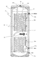
- FIG. 2 is a longitudinal sectional view of a hot water storage tank of the hot water storage type heating and hot water supply machine.
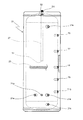
- FIG. 3 is a side view of a hot water storage tank of the hot water storage type hot water heater.
- FIG. 4 is a top view of a hot water storage tank of the hot water storage type heater / water heater.
- FIG. 5 is a longitudinal sectional view of a hot water storage tank of a hot water storage type hot water heater using the hot water storage type hot water heater according to the second embodiment of the present invention.
- FIG. 1 is a circuit diagram showing the configuration of a hot water storage type hot water heater using the hot water storage type hot water heater of the first embodiment of the present invention.
- FIG. 2 is a longitudinal sectional view of a hot water storage tank of the hot water storage type heating and hot water supply machine.
- FIG. 3 is
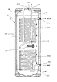
- FIG. 6 is a longitudinal sectional view of a hot water storage tank of a hot water storage type hot water heater using the hot water storage type hot water heater of the third embodiment of the present invention.
- FIG. 7 is a partial perspective view showing an internal structure of a hot water supply heat exchanger disposed in a hot water storage tank of a hot water storage type hot water heater using the hot water storage type hot water heater according to the fourth embodiment of the present invention.
- FIG. 8 is a longitudinal sectional view of a hot water storage tank of a hot water storage type hot water heater using the hot water storage type hot water heater of the fifth embodiment of the present invention.
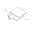
- FIG. 9 is a perspective view of a main part of a heat exchanger for hot water supply disposed in the hot water storage tank.
- FIG. 10 is a longitudinal sectional view of a hot water storage tank of a hot water storage type hot water heater using the hot water storage type water heater of the sixth embodiment of the present invention.
- FIG. 1 is a circuit diagram showing the configuration of a hot water storage type hot water heater using the hot water storage type hot water heater of the first embodiment of the present invention.
- this hot water storage type hot water heater includes a heat pump unit 1, a hot water storage part 2, and a heating hot water supply part that supplies hot water to a heater or a water heater (not shown).
- the heat pump unit 1 uses a CO 2 refrigerant that has a small global warming potential and does not destroy ozone. Thereby, the hot water temperature by the heat pump unit 1 can be made high (for example, 90 degreeC).
- the heat pump unit 1 includes a compressor 11, a condenser (water refrigerant heat exchanger) 12 having one end (primary side) connected to the discharge side of the compressor 11, and the other end (primary side) of the condenser 12. ), One end connected to the other end of the expansion valve 13, the other end connected to the suction side of the compressor 11, and the evaporator 14 with outside air. And a blower fan 15 to be supplied.
- the compressor 11, the condenser 12, the expansion valve 13 and the evaporator 14 constitute a refrigerant circuit.
- a discharge temperature sensor T1 for detecting the discharge temperature and a pressure sensor (HPS) 16 for detecting the discharge pressure are arranged on the discharge side of the compressor 11.
- an evaporator temperature sensor T2 for detecting the evaporator temperature is arranged in the evaporator 14, and an outside air temperature sensor T3 for detecting the outside air temperature is arranged in the vicinity of the evaporator 14.
- the boiling control unit (not shown) is connected to the compressor 11 and the expansion valve 13. The blower fan 15 and the like are controlled.
- one end of the pipe L11 is connected to a boiling forward connecting portion 21c (shown in FIG. 2) provided in the lower part of the hot water storage tank 21, and the other end of the pipe L11 is connected to one end (secondary side) of the condenser 12.
- a boiling circulation pump 24 for sending water from the bottom of the hot water storage tank 21 toward the condenser 12 is disposed in the pipe L11.
- One end of the pipe L12 is connected to the other end (secondary side) of the condenser 12 of the heat pump unit 1, and the other end of the pipe L12 is connected to the input side of the boiling three-way valve 25.
- One end of the pipe L24 is connected to one output side of the boiling three-way valve 25, and the other end of the pipe L24 is connected to one input side of the heating three-way valve 32. Further, one input side of the heating three-way valve 32 is connected to a second heating forward connection portion 21d (shown in FIG. 2 and also serves as a first heating return connection portion) provided on the upper portion of the hot water storage tank 21 via a pipe L35. ).
- a second heating forward connection portion 21d shown in FIG. 2 and also serves as a first heating return connection portion
- one end of the pipe L23 is connected to the other output side of the boiling three-way valve 25, and the other end of the pipe L23 is connected to the lower side of the hot water storage tank 21.
- An inlet water temperature sensor T4 that detects the incoming water temperature is disposed in the pipe L11 on the secondary side upstream of the condenser 12, and a hot water temperature sensor T5 that detects the outlet water temperature is provided in the pipe L12 on the downstream side of the condenser 12. It is arranged.
- the hot water storage tank 21 has a substantially cylindrical shape surrounded by a heat insulating material (not shown).
- a hot water supply heat exchanger 22 made of a coiled pipe is disposed in the hot water storage tank 21 .
- the hot water supply heat exchanger 22 has a lower coil portion 22a and an upper coil portion 22b connected with a predetermined interval.
- One end of the water supply pipe L21 connected to the hot water storage tank 21 is connected to the water supply port 21a connected to the lower end of the lower coil part 22a, and one end of the hot water supply pipe L22 connected to the hot water storage tank 21 is connected to the upper coil part 22b. Connected to the top.
- the water supply pipe L ⁇ b> 21 and the hot water supply pipe L ⁇ b> 22 are connected by a hot water supply mixing valve 31 outside the hot water storage tank 21.
- a hot water supply temperature sensor T13 is disposed downstream of the hot water supply pipe L22 from the hot water supply mixing valve 31.
- the water supplied from the outside through the water supply pipe L21 flows from the lower end side of the lower coil portion 22a toward the upper end side of the upper coil portion 22b, and a water heater (not shown) through the hot water supply pipe L22. To be supplied.
- the hot water storage tank 21 five temperature sensors T6 to T10 are arranged on the side surface so as to be separated from each other in order from the upper side to the lower side.
- the temperature sensor T6 detects the water temperature in the upper portion of the hot water storage tank 21, and the temperature sensor T8 detects the water temperature of the intermediate portion in the hot water storage tank 21. Further, the water temperature in the hot water storage tank 21 is detected by the temperature sensor T7 between the temperature sensor T6 and the temperature sensor T8. Further, the water temperature in the lower part of the hot water storage tank 21 is detected by the temperature sensor T10, and the water temperature in the hot water storage tank 21 is detected by the temperature sensor T9 between the temperature sensor T8 and the temperature sensor T10.
- five temperature sensors T6 to T10 for detecting the water temperature in the hot water storage tank 21 are provided. However, it is sufficient that there are four or more temperature sensors for detecting the water temperature in the hot water storage tank. By the plurality of temperature sensors, it is possible to determine to what height hot water is stored from above the hot water storage tank.
- an electric heater 23 is disposed in the hot water storage tank 21 and between the lower coil portion 22a and the upper coil portion 22b.
- the hot water storage tank 21, the hot water supply heat exchanger 22, the electric heater 23, the boiling circulation pump 24, the boiling three-way valve 25, and the temperature sensors T 6 to T 10 constitute the hot water storage section 2 (shown in FIG. 1). .
- one end of the pipe L31 is connected to the other input side of the heating three-way valve 32, and the other end of the pipe L31 is connected to the first heating forward connection 21f (shown in FIG. 2) of the hot water storage tank 21. ing.
- the first heating / outgoing connection portion 21 f is provided at a position between the upper coil portion 22 b of the hot water storage tank 21 and the electric heater 23.
- the output side of the heating three-way valve 32 is connected to one input side of the heating mixing valve 33, and one end of the pipe L32 is connected to the output side of the heating mixing valve 33.
- the piping L32 is provided with a heating temperature sensor T11 and a heating circulation pump 34 in order from the heating mixing valve 33 side.
- One end of radiators 41, 42,... As an example of a heating terminal is connected to the downstream side of the circulation pump 34 for heating of the pipe L32.
- one end of a pipe L33 is connected to a heating return connection portion 21g (shown in FIG. 3) provided as a heating return port provided in the lower part of the hot water storage tank 21, and the radiators 41, 42, The other end of each is connected.
- a heating return temperature sensor T12 is arranged in the pipe L33.
- the piping L33 connects the hot water storage tank 21 side to the heating return temperature sensor T12 and the other input side of the heating mixing valve 33 by a piping L34.
- a heating hot water supply control unit (not shown) and the heating three-way valve 25, the heating three-way valve 32, and the boiling
- the raising circulation pump 24 and the heating circulation pump 34 are controlled.
- the heating forward temperature sensor T11, the heating return temperature sensor T12, the hot water supply mixing valve 31, the heating three-way valve 32, the heating circulation pump 34, and the heating hot water supply control section constitute a heating hot water supply section driven by a commercial power source. Yes.
- the output side of the boiling three-way valve 25 of the hot water storage unit 2 is switched to the pipe L24 side, the compressor 11 of the heat pump unit 1 is driven, and the operation of the blower fan 15 is started. Furthermore, the boiling circulation pump 24 of the hot water storage unit 2 is driven. Then, after the high-pressure gas refrigerant discharged from the compressor 11 is radiated and condensed in the condenser 12 to become liquid refrigerant, the low-pressure refrigerant decompressed by the expansion valve 13 is heated from the outside air by the evaporator 14. Absorbs and evaporates. Then, the low-pressure gas refrigerant evaporated in the evaporator 14 returns to the suction side of the compressor 11.
- the water flowing into the secondary side of the condenser 12 from the lower part of the hot water storage tank 21 (boiling forward connection part 21c) via the pipe L11 by the boiling circulation pump 24 is heated by the condenser 12 to be 90%. It becomes hot water close to 0 ° C., and returns to the hot water storage tank 21 via the pipe L12, the three-way valve 25 for heating, the pipe L24, the pipe L35, and the second heating forward connection part (first boiling return connection part) 21d.
- the water in the hot water storage tank 21 is circulated through the boiling circulation pump 24 and the condenser 12, thereby boiling the water in the hot water storage tank 21.
- the hot water in the hot water storage tank 2 is formed with a hot water layer (temperature distribution) such that the hot water at the upper side is located at the upper side and the hot water at the lower side is located at the lower side.
- the heat pump unit 1 when the heat pump unit 1 is started up or the like, if the hot water coming out of the condenser 12 of the heat pump unit 1 is not yet sufficiently hot, the hot water returns to the upper part of the hot water storage tank 21 via the pipe L24 or the like. Instead, the three-way valve 25 is controlled so as to return to the second boiling return port at the lower part of the hot water storage tank 21 via the pipe L23. Thus, switching the return port according to the temperature of the hot water may prevent the temperature distribution in the hot water storage tank 21 from being disturbed if hot water that is not sufficiently high is returned to the upper part of the hot water storage tank 21. Because. The switching of the three-way valve 25 is performed based on the output of a tapping temperature sensor T5 provided between the condenser 12 and the three-way valve 25.
- the heating three-way valve 32 of the heating hot water supply unit 3 is switched so that the pipe L31 side and the heating mixing valve 33 side are connected, and the heating circulation pump 34 is driven.
- the hot water in the intermediate portion of the hot water storage tank 21 flows into the radiators 41, 42,... Via the pipe L31, the heating three-way valve 32, the heating mixing valve 33, and the heating circulation pump 34, respectively.
- the return warm water which came out of the said radiator 41,42, ... returns to the hot water storage tank 21 from the lower part of the hot water storage tank 21 via the piping L33.
- a heating and hot water supply control unit (not shown).
- the heating mixing valve 33 and the heating circulation pump 34 are controlled. Moreover, you may perform boiling-up by the heat pump unit 1 and heating operation simultaneously.
- the hot water in the hot water storage tank 21 when the high temperature region of the hot water in the hot water storage tank 21 exists from the upper part of the hot water storage tank 21 to the vicinity of the first heating outlet 51, the hot water is sufficiently stored.
- the three-way valve 32 for heating is controlled so that hot water is taken out from the intermediate part of the hot water storage tank 21 through the pipe L31 and circulated through the radiators 41, 42,. Further, when the hot water in the hot water storage tank 2 does not exist in the vicinity of the first heating outlet 51 and the high temperature water is present only in the upper part of the hot water storage tank 21, the hot water is not sufficiently stored. 2
- the heating three-way valve 32 is controlled so that hot water is taken out from the heating outlet 52 and circulated on the radiator side.
- the switching of the heating three-way valve 32 is performed by the heating hot water supply control unit.
- the heating and hot water supply control unit determines the amount of hot water based on signals from the plurality of temperature sensors T6 to T10 for detecting the temperature of the hot water in each part in the hot water storage tank 2, and thereby The valve 32 is switched.
- the switching of the heating three-way valve 32 may be performed based only on the temperature sensor T8 located slightly below the first heating outlet 51 and at substantially the same height as the electric heater 23.
- the hot water supply control unit controls the hot water supply mixing valve 31 to adjust the temperature of the hot water supplied to the water heater to a desired temperature.
- at least one of the heating operation or the boiling by the heat pump unit 1 and the hot water supply operation may be performed at the same time, and each operation is not limited.
- FIG. 2 shows a longitudinal sectional view of the hot water storage tank 21 of the hot water storage type heating and hot water heater
- FIG. 3 shows a side view of the hot water storage tank of the hot water storage type heating water heater
- FIG. 4 shows the hot water storage tank of the hot water storage type heating water heater.
- FIG. 2 is a cross-sectional view taken along line II-II shown in FIG.
- 21a is a water supply port
- 21b is a hot water supply port
- 21c is a boiling forward connecting portion
- 21d is a second heating outgoing connecting portion
- 21e is a second boiling return connecting portion
- 21f is a first heating outgoing port.
- connection part, 21g is a heating return connection part
- 26 is a sacrificial anode
- T6 to T10 are temperature sensors.
- the lower end of the pipe 27 provided substantially parallel to the sacrificial anode 26 in the hot water storage tank 21 from the first heating / outgoing connection portion 21f is open near the electric heater 23 and above, Hot water for heating is taken out from an intermediate portion in the hot water storage tank 21.
- a hot water supply heat exchanger 22 composed of a coiled pipe is disposed over substantially the entire vertical hot water storage tank 21 surrounded by a heat insulating material (not shown). is doing.
- the hot water supply heat exchanger 22 has a lower coil portion 22a and an upper coil portion 22b connected with a predetermined interval.
- the temperature distribution of the hot water gradually increases from the lower side to the upper side.
- the hot water having a low temperature flowing from the lower side of the heat exchanger 22 is heat-exchanged in a relatively low temperature hot water area on the lower side in the hot water storage tank 21, and hot water is stored as it flows toward the upper side of the hot water heat exchanger 22. Heat is exchanged in the hot water area on the upper side in the tank 21, and hot water is discharged as hot water.
- the heat exchange efficiency of the hot water heat exchanger 22 can be improved with a simple configuration, and high-temperature hot water can be supplied.
- the COP (coefficient of performance) of the heat pump unit 1 can be improved by heating the lower temperature water in the hot water storage tank 21 with the heat pump unit 1 while maintaining the temperature gradient in the vertical direction in the hot water storage tank 21.
- the hot water storage tank 21 has a temperature distribution of approximately 40 ° C. to 90 ° C. from the lower side to the upper side, and flows through the hot water temperature in the hot water storage tank 21 and the hot water supply heat exchanger 22.
- the temperature difference from the temperature of the water becomes smaller on the lower side where the low-temperature water flows and becomes smaller on the upper side. Therefore, when considering the uniform heat exchange amount in the hot water supply heat exchanger, the pitch of the lower portion of the hot water supply heat exchanger having a large temperature difference can be increased. Therefore, by shortening the length of the lower portion of the hot water heat exchanger, the vertical dimension of the hot water storage tank can be reduced, and the hot water storage tank can be reduced in size and weight.
- the hot water supply heat exchanger 22 can be arranged efficiently over substantially the entire vertical direction in the hot water storage tank 21.
- the heat pump unit 1 when the heat pump unit 1 has a shortage of capacity or at the time of failure, it is possible to use the electric heater 23 to heat the warm water in the intermediate portion in the hot water storage tank 21 and use the heating capacity of the electric heater 23 as an auxiliary. It becomes possible.
- the electric heater 23 is disposed on the lower side of the hot water storage tank 21, which takes time to heat up, by heating the hot water in the intermediate portion of the hot water storage tank 21 using the electric heater 23. Compared to the case, the rise of hot water heating can be improved.
- control of the electric heater 23 may be controlled based on, for example, the output of the temperature sensor T8 having substantially the same height as the electric heater 23 or the temperature sensor T7 positioned slightly above the electric heater 23. That is, when the water temperature detected by the temperature sensor T7 is lower than the predetermined temperature (that is, when the predetermined high-temperature water is only up to a position above the temperature sensor T7), the amount of the high-temperature water in the hot water storage tank 21 is If it is determined that the electric heater 23 is not sufficient, the electric heater 23 is turned on, and the electric heater 23 is turned on until the water temperature detected by the temperature sensor T8 is equal to or higher than the predetermined temperature (that is, the predetermined high-temperature water is at the position of the temperature sensor T8).
- the electric heater 23 is turned off when the water temperature detected by the temperature sensor T8 becomes equal to or higher than a predetermined temperature. Instead of the temperature sensor T8 located at almost the same height as the electric heater 23, the temperature sensor T7 located slightly higher than the electric heater 23 and the temperature sensor T8 almost the same height as the electric heater 23 are used. The reason for controlling on / off is to prevent hunting. As is clear from FIG. 3, the first heating outlet 51 is located between the second temperature sensor T7 from the top and the third temperature sensor T8 from the top, which is approximately the same height as the electric heater 23. Located in.
- the first heating door 51 is electrically heated.
- the electric heater 23 is off and the heating outlet is the first heating outlet 51.
- the electric heater 23 is turned off and the heating outlet becomes the second heating outlet 52.
- the electric heater 23 is not in the lower part of the hot water storage tank 21 but in the lower position in the vicinity of the first heating outlet 51, the time for raising the temperature between the temperature sensors T8 and T7 to a predetermined temperature. That is, it is possible to shorten the time for returning from the state (3) to the state (1). Accordingly, the time required to use the second heating outlet 52 can be reduced, and in particular, as a hot water heating / heating system using mainly hot water in the upper part of the tank for hot water supply and hot water in the lower part of the hot water storage tank 21 for heating. Is preferred.
- the heat exchange efficiency of the hot water heat exchanger 22 can be improved with a simple configuration, hot hot water can be supplied, and the upper region in the hot water storage tank 21 is mainly used for hot water supply.
- the heat source in the upper region in the hot water storage tank 21 is effectively used to supply high-temperature hot water while affecting high-temperature hot water supply. Therefore, the heat source in the lower region in the hot water storage tank 21 can be effectively used for heating.
- the hot water in the upper region in the hot water storage tank 21 can be maintained at a high temperature for hot water supply. It is possible to prevent a decrease in hot water supply capacity due to heating.
- thermocouples may be used.
- FIG. 5 is a longitudinal sectional view of a hot water storage tank of a hot water storage type hot water heater using the hot water storage type hot water heater according to the second embodiment of the present invention.
- the pitch of the lower coil part 122a of the hot water supply heat exchanger 122 arranged in the hot water storage tank 21 is roughened, and the pitch of the upper coil part 122b is made dense. . Specifically, the ratio of the pitch of the upper coil portion 122b to the pitch of the lower coil portion 122a is approximately 0.7.
- each of the lower coil part 122a and the upper coil part 122 is wound at equal intervals.
- the hot water storage type heating and hot water heater of the second embodiment has the same effect as the hot water storage type heating and hot water heater of the first embodiment.
- the hot water storage tank 21 has an internal temperature.
- the upper coil portion of the hot water supply heat exchanger 22 is controlled in the upper hot water area in the hot water storage tank 21 as it flows toward the upper side of the hot water supply heat exchanger 22 while suppressing the temperature rise in the lower hot water area.
- the pitch of 22b dense heat exchange is sufficiently performed, and hot hot water is obtained.
- the COP of the heat pump unit 1 can be further improved by providing a larger temperature gradient in the upper and lower parts of the hot water storage tank 21 and heating the lower temperature water in the hot water storage tank 21 with the heat pump unit 1.
- the pitch of the upper coil portion 22b is made denser than the pitch of the lower coil portion 22a of the hot water supply heat exchanger 22, but instead of adjusting the pitch, the length of the pipe of the lower coil portion is long.
- the sheath diameter may be reduced.
- the hot water storage tank is made by roughening the pitch of the lower coil part 122a of the heat exchanger 122 for hot water supply arrange
- the heat exchange capacity of the heat exchanger for hot water supply per unit volume of the upper part is larger than the lower part, but instead of adjusting the pitch, the pipe length and the drawing diameter of the lower coil part are reduced. Also good.
- the heat transfer coefficient of the heat transfer tube part in the upper part may be improved from the lower part,
- the inner diameter of the heat transfer tube of the annular coil in the upper part of the heat exchanger for hot water supply smaller than the inner diameter of the heat transfer tube of the annular coil in the lower part, by increasing the flow rate of the water flowing through the heat transfer tube, You may improve the heat transfer rate of the heat exchanger tube part of a part rather than a lower part.
- the hot water storage type heating and hot water heater has been described, but it is needless to say that the present invention may be applied to a hot water storage type hot water heater that performs only hot water supply.
- the shape and pitch of the lower coil portion 22a (122a) and the upper coil portion 22b (122b) of the hot water supply heat exchanger 22 (122) are the same as the shape of the hot water storage tank. What is necessary is just to set suitably according to.
- the electrothermal heater 23 was used as an example of the heater arrange
- the heating terminal is not limited to the radiator, and other means such as a floor heating panel and a fan coil may be used.
- FIG. 6 is a longitudinal sectional view of a hot water storage tank of a hot water storage type hot water heater using the hot water storage type hot water heater of the third embodiment of the present invention.
- the hot water storage type heating and hot water heater of the third embodiment has the same configuration as the hot water storage type heating and hot water heater of the first embodiment except for a heat exchanger for hot water supply, and the same components are denoted by the same reference numerals. The description is omitted.
- a hot water supply heat exchanger 222 made of a coiled pipe is disposed in the hot water storage tank 21.
- This hot water supply heat exchanger 222 has a lower coil part 222a and an upper coil part 222b connected at a predetermined interval, and the inner diameter of the upper coil part 222b is smaller than the inner diameter of the lower coil part 222a. I have to.
- the hot water storage type heating and hot water heater of the third embodiment has the same effect as the hot water storage type heating and hot water heater of the first embodiment, and by making the inner diameter of the upper coil portion 222b of the hot water supply heat exchanger 222 small. Since the flow rate in the upper coil portion 222b is increased and the heat transfer coefficient is improved, heat exchange is sufficiently performed in the upper hot water area in the hot water storage tank 21 to obtain hot hot water.
- FIG. 7 is a partial perspective view showing an internal structure of a hot water supply heat exchanger disposed in a hot water storage tank of a hot water storage type hot water heater using the hot water storage type hot water heater according to the fourth embodiment of the present invention.
- the hot water storage type heating hot water supply apparatus of the fourth embodiment has the same configuration as the hot water storage type heating water heater of the first embodiment except for a heat exchanger for hot water supply, and FIG.
- the hot water supply heat exchanger 22 composed of a coiled pipe disposed in the hot water storage tank 21 is connected to the lower coil portion 22a connected at a predetermined interval. As shown in FIG. 7, a plurality of spiral grooves 60 are provided on the inner surface of the upper coil portion 22b (inner surface processed tube).
- the lower coil portion 22a is an inner smooth tube.
- the hot water storage type hot water heater of the fourth embodiment has the same effect as the hot water storage type hot water heater of the first embodiment, and the groove 60 provided on the inner surface of the upper coil portion 22b of the hot water supply heat exchanger 22. As a result, the heat transfer coefficient of the upper coil portion 22b is improved, so that heat exchange is sufficiently performed in the upper hot water area in the hot water storage tank 21, and hot hot water is obtained.
- channel provided in the inner surface of the upper coil part of the heat exchanger for hot water supply is not restricted to a spiral shape, A groove
- FIG. 8 is a longitudinal sectional view of a hot water storage tank of a hot water storage type hot water heater using the hot water storage type hot water heater of the fifth embodiment of the present invention.
- the hot water storage type heating and hot water heater of the fifth embodiment has the same configuration as the hot water storage type heating and hot water heater of the first embodiment except for the fins of the heat exchanger for hot water supply, and the same components have the same reference numerals. A description thereof will be omitted.
- a hot water supply heat exchanger 322 made of a coiled pipe is arranged in the hot water storage tank 21.
- This hot water supply heat exchanger 322 has a lower coil part 322a and an upper coil part 322b connected with a predetermined interval, and a plate-like fin 70 is provided on the upper outer peripheral surface of the upper coil part 322b. (See FIG. 9).
- the plate-like fin 70 has an outer diameter and an inner diameter dimension corresponding to the coil shape of the upper coil portion 322b in a plan view, and is configured by a C-shaped annular plate material in which a part in the circumferential direction is cut away. ing.
- the notched portion of the plate-like fin 70 serves as an insertion portion for a pipe that is wound and transferred from the lower stage side to the upper stage side.
- the plate-like fins 70 are respectively disposed between the coil-shaped pipes of the upper coil portion 322b and are stacked in the vertical direction.
- the hot water storage type heating and hot water heater of the fifth embodiment has the same effect as the hot water storage type heating and hot water heater of the first embodiment, and is provided on the outer peripheral surface of the upper coil portion 322b of the hot water supply heat exchanger 322. Since the heat transfer coefficient of the upper coil portion 322b is improved by the shaped fins 70, heat exchange is sufficiently performed in the upper high temperature hot water area in the hot water storage tank 21, and high temperature hot water is obtained.
- FIG. 10 is a longitudinal sectional view of a hot water storage tank of a hot water storage type hot water heater using the hot water storage type water heater of the sixth embodiment of the present invention.
- the hot water storage type heating and hot water heater of the sixth embodiment has the same configuration as the hot water storage type heating and hot water heater of the first embodiment except for the fins of the heat exchanger for hot water supply, and the same components have the same reference numerals. A description thereof will be omitted.
- a hot water supply heat exchanger 422 made of a coiled pipe is arranged in the hot water storage tank 21.
- This hot water supply heat exchanger 422 has a lower coil portion 422a and an upper coil portion 422b connected with a predetermined interval, and a spiral fin 80 is provided on the outer peripheral surface of the upper coil portion 422b. .
- the hot water storage type heating hot water heater of the sixth embodiment has the same effect as the hot water storage type heating hot water heater of the first embodiment, and the spiral provided on the outer peripheral surface of the upper coil portion 422b of the hot water supply heat exchanger 422. Since the heat transfer coefficient of the upper coil part 422b is improved by the fin-shaped fin 80, heat exchange is sufficiently performed in the upper hot water area in the hot water storage tank 21, and hot hot water is obtained.
- the plate-like fins 70 are provided in the upper coil portion 322b.
- the spiral fins 80 are provided in the upper coil portion 422b. Any fin that improves the heat transfer coefficient of the coil portion may be used.
Landscapes
- Engineering & Computer Science (AREA)
- Physics & Mathematics (AREA)
- Thermal Sciences (AREA)
- Mechanical Engineering (AREA)
- General Engineering & Computer Science (AREA)
- Chemical & Material Sciences (AREA)
- Combustion & Propulsion (AREA)
- Geometry (AREA)
- Water Supply & Treatment (AREA)
- Heat-Pump Type And Storage Water Heaters (AREA)
- Details Of Fluid Heaters (AREA)
- Steam Or Hot-Water Central Heating Systems (AREA)
Abstract
水を加熱するためのヒートポンプユニット1と、ヒートポンプユニット1により加熱された温水を貯える貯湯タンク21と、貯湯タンク21内の上下方向略全体にわたって配置され、下側から入水して上側から出湯するコイル状のパイプを含む給湯用熱交換器22とを備える。
Description
この発明は、貯湯式給湯機および貯湯式暖房給湯機に関する。
従来、貯湯式給湯機としては、水を加熱するヒートポンプユニットと、ヒートポンプユニットにより加熱された温水を貯える貯湯タンクとを備え、貯湯タンク内の温水を利用して暖房や給湯を行う貯湯式暖房給湯機がある(例えば、特開2006-329581号公報参照)。
上記貯湯式暖房給湯機では、貯湯タンク内に貯えられた温水がそのまま出湯されるのに対して、衛生面などを考慮して貯湯タンク内に給湯用熱交換器を配置し、給水口から給湯用熱交換器を介して出湯するものがある。このような給湯用熱交換器を用いた貯湯式暖房給湯機では、貯湯タンク内の温水と給湯水との間で効率よく熱交換できる給湯用熱交換器を実現することは容易でないという問題がある。
そこで、この発明の課題は、簡単な構成で給湯用熱交換器の熱交換効率を向上でき、高温の給湯水を供給できる貯湯式給湯機および貯湯式暖房給湯機を提供することにある。
上記課題を解決するため、この発明の貯湯式給湯機は、
水を加熱するためのヒートポンプユニットと、
上記ヒートポンプユニットにより加熱された温水を貯える貯湯タンクと、
上記貯湯タンク内の上下方向略全体にわたって配置され、下側から入水して上側から出湯するパイプを含む給湯用熱交換器と
を備えたことを特徴とする。
水を加熱するためのヒートポンプユニットと、
上記ヒートポンプユニットにより加熱された温水を貯える貯湯タンクと、
上記貯湯タンク内の上下方向略全体にわたって配置され、下側から入水して上側から出湯するパイプを含む給湯用熱交換器と
を備えたことを特徴とする。
上記構成の貯湯式給湯機によれば、ヒートポンプユニットにより加熱された温水を貯えた貯湯タンクにおいて、温水の温度分布が下側から上側に向かって徐々に高くなった状態で、パイプを含む給湯用熱交換器の下側から流入した温度の低い給湯水は、貯湯タンク内の下側の比較的低温の温水域で熱交換され、給湯用熱交換器の上側に向かって流れるに従って貯湯タンク内の上側の高温の温水域で熱交換されて、高温の給湯水となって出湯される。このように、上記貯湯タンク内の温度勾配に従って給湯水が下から上に向かって熱交換により加熱されながら流れるので、貯湯タンク内の温度分布が乱れることがなく、高い熱交換効率が得られる。したがって、簡単な構成で給湯用熱交換器の熱交換効率を向上でき、高温の給湯水を供給できる。また、上記貯湯タンク内の上下方向に温度勾配を設けて、貯湯タンク内の下側の低温水をヒートポンプユニットで加熱することにより、ヒートポンプユニットのCOP(成績係数)を向上できる。
また、一実施形態の貯湯式給湯機では、上記貯湯タンクの単位容積あたりの上記給湯用熱交換器の熱交換能力を下側部分よりも上側部分を大きくした。
上記実施形態によれば、貯湯タンク内の下側部分の比較的低温の温水域では、貯湯タンクの単位容積あたりの給湯用熱交換器の熱交換能力を上側部分よりも下側部分を小さくすることにより、上側部分と下側部分の熱交換能力が同一のときよりも熱交換が抑えられて、貯湯タンク内の下側の温水域の冷却を抑制する。これにより、貯湯タンク内の温水を熱源として暖房する場合に、暖房能力不足を防ぐことができる。
一方、給湯用熱交換器の上側に向かって流れるに従って貯湯タンク内の上側の高温の温水域では、貯湯タンクの単位容積あたりの給湯用熱交換器の熱交換能力を下側部分よりも上側部分を大きくすることにより熱交換が十分に行われるので、高温の給湯水が得られる。
また、一実施形態の貯湯式給湯機では、上記給湯用熱交換器は、コイル状のパイプを含む。
上記実施形態によれば、給湯用熱交換器にコイル状のパイプを用いることによって、貯湯タンク内の上下方向略全体にわたって給湯用熱交換器を効率よく配置できる。
また、一実施形態の貯湯式給湯機では、
上記給湯用熱交換器は、下側コイル部と上側コイル部を有し、
上記下側コイル部と上記上側コイル部との間に配置された電熱ヒータを備えた。
上記給湯用熱交換器は、下側コイル部と上側コイル部を有し、
上記下側コイル部と上記上側コイル部との間に配置された電熱ヒータを備えた。
上記実施形態によれば、上記給湯用熱交換器の下側コイル部と上側コイル部との間に電熱ヒータを配置することによって、ヒートポンプユニットが容量不足のときや故障時は、電熱ヒータを用いて貯湯タンク内の中間部の温水を加熱して、電熱ヒータの加熱能力を補助的に利用することが可能となる。また、ヒートポンプユニットが故障したとき、電熱ヒータを用いて貯湯タンク内の中間部の温水を加熱することによって、沸き上げに時間のかかる貯湯タンク内の下側に電熱ヒータを配置した場合に比べて、給湯加熱の立ち上がりを向上できる。
また、一実施形態の貯湯式給湯機では、上記給湯用熱交換器の上記コイル状のパイプは、下側のピッチよりも上側のピッチが密である。
上記実施形態によれば、貯湯タンク内の下側の比較的低温の温水域では、給湯用熱交換器のコイル状のパイプのピッチを粗にすることにより、上側部分と下側部分が同一ピッチのときよりも熱交換が抑えられて、貯湯タンク内の下側の温水域の冷却を抑制する。これにより、貯湯タンク内の温水を熱源として暖房する場合に、暖房能力不足を防ぐことができる。
一方、給湯用熱交換器の上側に向かって流れるに従って貯湯タンク内の上側の高温の温水域では、給湯用熱交換器のコイル状のパイプのピッチを密にすることにより熱交換が十分に行われて、高温の給湯水が得られる。
また、一実施形態の貯湯式給湯機では、上記給湯用熱交換器の上記コイル状のパイプは、下側部分の内径よりも上側部分の内径が小径である。
上記実施形態によれば、給湯用熱交換器のコイル状のパイプのうちの上側部分の内径を、下側部分の内径よりも小径にすることによって、上側部分のパイプ内の流速が速くなって熱伝達率が向上するので、貯湯タンク内の上側の高温の温水域で熱交換が十分に行われて、高温の給湯水が得られる。
また、一実施形態の貯湯式給湯機では、上記給湯用熱交換器の上記コイル状のパイプのうちの上側部分の内面に溝を設けた。
上記実施形態によれば、給湯用熱交換器のコイル状のパイプのうちの上側部分の内面に溝を設けることによって、コイル状のパイプの上側部分の熱伝達率が向上するので、貯湯タンク内の上側の高温の温水域で熱交換が十分に行われて、高温の給湯水が得られる。
また、一実施形態の貯湯式給湯機では、上記給湯用熱交換器の上記コイル状のパイプのうちの上側部分の外周面にフィンを設けた。
上記実施形態によれば、給湯用熱交換器のコイル状のパイプのうちの上側部分の外周面にフィンを設けることによって、コイル状のパイプの上側部分の熱伝達率が向上するので、貯湯タンク内の上側の高温の温水域で熱交換が十分に行われて、高温の給湯水が得られる。
また、一実施形態の貯湯式給湯機では、上記ヒートポンプユニットは、二酸化炭素を冷媒として用いた。
上記実施形態によれば、上記ヒートポンプユニットに二酸化炭素を冷媒として用いることによって、二酸化炭素は地球温暖化係数が小さくオゾンを破壊しないので、地球温暖化対策に貢献でき、さらに二酸化炭素はHFC冷媒などに比べて凝縮温度が高いので、ヒートポンプユニットによる出湯温度を高くできる(例えば90℃)。
また、この発明の貯湯式暖房給湯機では、
上記のいずれか1つの貯湯式給湯機と、
上記貯湯式給湯機の上記貯湯タンクの暖房往き口と暖房戻り口との間に接続された暖房端末と、
上記貯湯タンク内の温水を上記暖房端末を介して循環させる循環ポンプと
を備え、
上記貯湯タンク内の上側領域を主に給湯の熱源として用い、上記貯湯タンク内の下側領域を主に暖房の熱源として用いたことを特徴とする。
上記のいずれか1つの貯湯式給湯機と、
上記貯湯式給湯機の上記貯湯タンクの暖房往き口と暖房戻り口との間に接続された暖房端末と、
上記貯湯タンク内の温水を上記暖房端末を介して循環させる循環ポンプと
を備え、
上記貯湯タンク内の上側領域を主に給湯の熱源として用い、上記貯湯タンク内の下側領域を主に暖房の熱源として用いたことを特徴とする。
上記構成によれば、簡単な構成で貯湯式給湯機の給湯用熱交換器の熱交換効率を向上でき、高温の給湯水を供給できる。さらに、上記貯湯タンク内の上側領域を主に給湯の熱源として用いると共に、下側領域を主に暖房の熱源として用いることによって、貯湯タンク内の上側領域の熱源を有効に利用して、高温の給湯水を供給しつつ、高温給湯に影響を及ぼすことなく、貯湯タンク内の下側領域の熱源を暖房に有効利用できる。
また、一実施形態の貯湯式暖房給湯機では、上記循環ポンプにより上記貯湯タンク内の中間領域から上記暖房端末に出湯される。
上記実施形態によれば、上記循環ポンプにより貯湯タンク内の中間領域から暖房端末に出湯することによって、貯湯タンク内の上側領域の温水を給湯用に高温状態に維持することができ、暖房による給湯能力の低下を防止できる。
以上より明らかなように、この発明の貯湯式給湯機によれば、簡単な構成で給湯用熱交換器の熱交換効率を向上でき、高温の給湯水を供給できる貯湯式給湯機を実現することができる。
また、一実施形態の貯湯式給湯機によれば、貯湯タンクの単位容積あたりの給湯用熱交換器の熱交換能力を下側部分よりも上側部分を大きくすることによって、貯湯タンク内の下側部分の比較的低温の温水域では、上側部分と下側部分の熱交換能力が同一のときよりも熱交換が抑えられて、貯湯タンク内の下側の温水域の冷却を抑制することにより、貯湯タンク内の温水を熱源として暖房する場合に、暖房能力不足を防ぐことができる一方、給湯用熱交換器の上側に向かって流れるに従って貯湯タンク内の上側の高温の温水域では、熱交換が十分に行われるので、高温の給湯水が得られる。
また、一実施形態の貯湯式給湯機によれば、給湯用熱交換器にコイル状のパイプを用いることによって、貯湯タンク内の上下方向略全体にわたって給湯用熱交換器を効率よく配置することができる。
また、一実施形態の貯湯式給湯機によれば、上記給湯用熱交換器の下側コイル部と上側コイル部との間に電熱ヒータを配置することによって、ヒートポンプユニットが容量不足のときや故障時は、電熱ヒータを用いて貯湯タンク内の中間部の温水を加熱して、電熱ヒータの加熱能力を補助的に利用することが可能となると共に、ヒートポンプユニットが故障したとき、電熱ヒータを用いて貯湯タンク内の中間部の温水を加熱することによって、沸き上げに時間のかかる貯湯タンク内の下側に電熱ヒータを配置した場合に比べて、給湯加熱の立ち上がりを向上できる。
また、一実施形態の貯湯式給湯機によれば、貯湯タンク内の下側の比較的低温の温水域では、給湯用熱交換器のコイル状のパイプのピッチを粗にすることにより、上側部分と下側部分が同一ピッチのときよりも熱交換が抑えられて、貯湯タンク内の下側の温水域の冷却を抑制することにより、貯湯タンク内の温水を熱源として暖房する場合に、暖房能力不足を防ぐことができる一方、給湯用熱交換器の上側に向かって流れるに従って貯湯タンク内の上側の高温の温水域では、給湯用熱交換器のコイル状のパイプのピッチを密にすることにより熱交換が十分に行われるので、高温の給湯水が得られる。
また、一実施形態の貯湯式給湯機によれば、給湯用熱交換器のコイル状のパイプのうちの上側部分の内径を、下側の部分の内径よりも小径にすることによって、上側部分のパイプ内の流速が速くなって熱伝達率が向上するので、貯湯タンク内の上側の高温の温水域で熱交換が十分に行われて、高温の給湯水が得られる。
また、一実施形態の貯湯式給湯機によれば、給湯用熱交換器のコイル状のパイプのうちの上側部分の内面に溝を設けることによって、コイル状のパイプの上側部分の熱伝達率が向上するので、貯湯タンク内の上側の高温の温水域で熱交換が十分に行われて、高温の給湯水が得られる。
また、一実施形態の貯湯式給湯機によれば、給湯用熱交換器のコイル状のパイプのうちの上側部分の外周面にフィンを設けることによって、コイル状のパイプの上側部分の熱伝達率が向上するので、貯湯タンク内の上側の高温の温水域で熱交換が十分に行われて、高温の給湯水が得られる。
また、一実施形態の貯湯式給湯機によれば、ヒートポンプユニットに二酸化炭素を冷媒として用いることによって、地球温暖化対策に貢献でき、さらにHFC冷媒などに比べて凝縮温度が高いので、ヒートポンプユニットによる出湯温度を高くすることができる。
また、この発明の貯湯式暖房給湯機によれば、簡単な構成で給湯用熱交換器の熱交換効率を向上でき、高温の給湯水を供給できると共に、貯湯タンク内の上側領域を主に給湯の熱源として用い、下側領域を主に暖房の熱源として用いることによって、貯湯タンク内の上側領域の熱源を有効に利用して、高温の給湯水を供給しつつ、高温給湯に影響を及ぼすことなく、貯湯タンク内の下側領域の熱源を暖房に有効利用できる。
また、一実施形態の貯湯式暖房給湯機によれば、上記循環ポンプにより貯湯タンク内の中間領域から暖房端末に出湯することによって、貯湯タンク内の上側領域の温水を給湯用に高温状態に維持することができ、暖房による給湯能力の低下を防止できる。
以下、この発明の貯湯式給湯機および貯湯式暖房給湯機を図示の実施の形態により詳細に説明する。
〔第1実施形態〕
図1はこの発明の第1実施形態の貯湯式給湯機を用いた貯湯式暖房給湯機の構成を示す回路図である。
図1はこの発明の第1実施形態の貯湯式給湯機を用いた貯湯式暖房給湯機の構成を示す回路図である。
この貯湯式暖房給湯機は、図1に示すように、ヒートポンプユニット1と、貯湯部2と、図示しない暖房器や給湯器に温水を供給する暖房給湯部を備えている。上記ヒートポンプユニット1には、地球温暖化係数が小さくオゾンを破壊しないCO2冷媒を用いている。これにより、ヒートポンプユニット1による出湯温度を高くできる(例えば90℃)。
上記ヒートポンプユニット1は、圧縮機11と、上記圧縮機11の吐出側に一端(一次側)が接続された凝縮器(水冷媒熱交換器)12と、上記凝縮器12の他端(一次側)に一端が接続された膨張弁13と、上記膨張弁13の他端に一端が接続され、他端が圧縮機11の吸込側に接続された蒸発器14と、上記蒸発器14に外気を供給する送風ファン15とを有している。上記圧縮機11と凝縮器12と膨張弁13および蒸発器14で冷媒回路を構成している。
また、上記圧縮機11の吐出側に、吐出温度を検出する吐出温度センサT1を配置すると共に、吐出圧力を検出する圧力センサ(HPS)16を配置している。また、上記蒸発器14に蒸発器温度を検出する蒸発器温度センサT2を配置し、蒸発器14近傍に、外気温度を検出する外気温度センサT3を配置している。そして、上記吐出温度センサT1と蒸発器温度センサT2と外気温度センサT3および圧力センサ(HPS)16の検出信号に基づいて、沸き上げ制御部(図示せず)は、圧縮機11,膨張弁13,送風ファン15などを制御する。
また、上記貯湯タンク21の下部に設けられた沸き上げ往き接続部21c(図2に示す)に配管L11の一端を接続し、その配管L11の他端を凝縮器12の一端(二次側)に接続している。上記配管L11に、貯湯タンク21下部から凝縮器12側に向かって水を送出する沸き上げ用循環ポンプ24を配設している。上記ヒートポンプユニット1の凝縮器12の他端(二次側)に配管L12の一端を接続し、その配管L12の他端を沸き上げ用三方弁25の入力側に接続している。上記沸き上げ用三方弁25の一方の出力側に配管L24の一端を接続し、その配管L24の他端を暖房用三方弁32の一方の入力側に接続している。さらに、上記暖房用三方弁32の一方の入力側を配管L35を介して貯湯タンク21の上部に設けられた第2暖房往き接続部21d(図2に示し、第1沸き上げ戻り接続部を兼ねる)に接続している。一方、沸き上げ用三方弁25の他方の出力側に配管L23の一端を接続し、その配管L23の他端を貯湯タンク21の下側に接続している。
上記凝縮器12の二次側上流の配管L11に、入水温度を検出する入水温度センサT4を配置し、凝縮器12の二次側下流の配管L12に、出湯温度を検出する出湯温度センサT5を配置している。
また、上記貯湯タンク21は、断熱材(図示せず)で囲まれた略円筒形状をしている。上記貯湯タンク21内に、コイル状のパイプからなる給湯用熱交換器22を配置している。この給湯用熱交換器22は、所定の間隔をあけて接続された下側コイル部22aと上側コイル部22bとを有している。上記貯湯タンク21に接続された給水配管L21の一端を、下側コイル部22aの下端に連なる給水口21aに接続し、貯湯タンク21に接続された給湯配管L22の一端を、上側コイル部22bの上端と接続している。上記給水配管L21と給湯配管L22は、貯湯タンク21の外側で給湯用混合弁31により接続されている。また、上記給湯配管L22の給湯用混合弁31よりも下流側に給湯温度センサT13を配置している。
上記給水配管L21を介して外部から供給された水は、下側コイル部22aの下端側から上側コイル部22bの上端側に向かって流れて、給湯配管L22を介して給湯器(図示せず)に供給される。
また、上記貯湯タンク21は、側面に5つの温度センサT6~T10を上側から下側に向かって順に互いに離間し配置している。上記温度センサT6により貯湯タンク21内の上側部分の水温を検出し、温度センサT8により貯湯タンク21内の中間部分の水温を検出する。また、上記温度センサT6と温度センサT8の中間で温度センサT7により貯湯タンク21内の水温を検出する。また、上記温度センサT10により貯湯タンク21内の下側部分の水温を検出し、温度センサT8と温度センサT10の中間で温度センサT9により貯湯タンク21内の水温を検出する。本実施形態では、貯湯タンク21内の水温を検出する5つの温度センサT6~T10を設けたが、貯湯タンク内の水温を検出する温度センサは4以上複数あればよい。複数の温度センサにより、給湯水が貯湯タンクの上からどの高さまで貯湯されているか判断することができる。
また、上記貯湯タンク21内かつ下側コイル部22aと上側コイル部22bとの間に電熱ヒータ23を配置している。
上記貯湯タンク21と給湯用熱交換器22と電熱ヒータ23と沸き上げ用循環ポンプ24と沸き上げ用三方弁25および温度センサT6~T10で貯湯部2(図1に示す)を構成している。
次に、上記暖房用三方弁32の他方の入力側に配管L31の一端を接続し、その配管L31の他端を貯湯タンク21の第1暖房往き接続部21f(図2に示す)に接続している。上記第1暖房往き接続部21fは、貯湯タンク21の上側コイル部22bと電熱ヒータ23との間の位置に設けられている。
そして、上記暖房用三方弁32の出力側を暖房用混合弁33の一方の入力側に接続し、その暖房用混合弁33の出力側に配管L32の一端を接続している。上記配管L32に、暖房用混合弁33側から順に暖房往き温度センサT11と暖房用循環ポンプ34を配設している。上記配管L32の暖房用循環ポンプ34よりも下流側に、暖房端末の一例としてのラジエータ41,42,…の一端を夫々接続している。また、上記貯湯タンク21の下部に設けられた暖房戻り口としての暖房戻り接続部21g(図3に示す)に配管L33の一端を接続し、その配管L33の他端側にラジエータ41,42,…の他端を夫々接続している。上記配管L33に暖房戻り温度センサT12を配置している。また、上記配管L33の暖房戻り温度センサT12よりも貯湯タンク21側と、暖房用混合弁33の他方の入力側とを配管L34により接続している。
上記温度センサT6~T10と暖房往き温度センサT11および暖房戻り温度センサT12からの検出信号に基づいて、暖房給湯制御部(図示せず)により沸き上げ用三方弁25と暖房用三方弁32と沸き上げ用循環ポンプ24と暖房用循環ポンプ34を制御する。
上記暖房往き温度センサT11と暖房戻り温度センサT12と給湯用混合弁31と暖房用三方弁32と暖房用循環ポンプ34および暖房給湯制御部が、商用電源により駆動される暖房給湯部を構成している。
上記構成の貯湯式暖房給湯機において、貯湯部2の沸き上げ用三方弁25の出力側を配管L24側に切り換え、ヒートポンプユニット1の圧縮機11を駆動すると共に送風ファン15の運転を開始する。さらに、貯湯部2の沸き上げ用循環ポンプ24を駆動する。そうすると、圧縮機11から吐出された高圧ガス冷媒は、凝縮器12で放熱して凝縮することにより液冷媒となった後、膨張弁13で減圧された低圧冷媒は、蒸発器14で外気から熱を吸収して蒸発する。そうして、蒸発器14で蒸発した低圧ガス冷媒は、圧縮機11の吸込側に戻る。このとき、沸き上げ用循環ポンプ24により貯湯タンク21の下部(沸き上げ往き接続部21c)から配管L11を介して凝縮器12の二次側に流入した水は、凝縮器12で加熱されて90℃近い温水となり、配管L12,沸き上げ用三方弁25,配管L24,配管L35,第2暖房往き接続部(第1沸き上げ戻り接続部)21dを介して貯湯タンク21内に戻る。こうして、貯湯タンク21内の水を沸き上げ用循環ポンプ24と凝縮器12を介して循環させることにより、貯湯タンク21内の水を沸き上げる。貯湯タンク2内の温水は、上側に高温の温水、下側に比較的低温の温水が位置するように湯層(温度分布)が形成されている。
なお、ヒートポンプユニット1の起動時などの際、まだヒートポンプユニット1の凝縮器12から出る温水が十分に高温となっていない場合、該温水は配管L24等を介して貯湯タンク21の上部に戻るのではなく、配管L23を介して貯湯タンク21の下部の第2の沸き上げ戻り口に戻るように、三方弁25を制御する。このように、温水の温度により戻り口を切り替えるのは、十分に高温になっていない温水を貯湯タンク21の上部に戻すと貯湯タンク21内の温度分布が乱れる可能性があり、これを防止するためである。この三方弁25の切り替えは、凝縮器12と三方弁25との間に設けられた出湯温度センサT5の出力に基づいて行われる。
次に、暖房運転を行う場合、暖房給湯部3の暖房用三方弁32を、配管L31側と暖房用混合弁33側が接続されるように切り換えて、暖房用循環ポンプ34を駆動する。そうすると、貯湯タンク21の中間部の温水が配管L31,暖房用三方弁32,暖房用混合弁33,暖房用循環ポンプ34を介してラジエータ41,42,…に夫々流入する。そして、上記ラジエータ41,42,…から出た戻り温水は、配管L33を介して貯湯タンク21の下部から貯湯タンク21内に戻る。
ここで、上記温度センサT6~T10からの検出信号と暖房往き温度センサT11により検出された暖房往き温度および暖房戻り温度センサT12により検出された暖房戻り温度に基づいて、暖房給湯制御部(図示せず)により暖房用混合弁33および暖房用循環ポンプ34を制御する。また、ヒートポンプユニット1による沸き上げと暖房運転を同時に行ってもよい。
暖房用三方弁32の切り替えについては、貯湯タンク21内の温水の高温領域が貯湯タンク21の上部から第1暖房往き口51近傍にまで存在しており、高温水が十分に貯湯されている場合、貯湯タンク21の中間部から配管L31を介して温水を取り出してラジエータ41,42,…側を循環するように、暖房用三方弁32を制御する。また、貯湯タンク2内の温水の高温領域が第1暖房往き口51近傍にまで存在しておらず、高温水が貯湯タンク21の上部にしか存在しないなど、十分に貯湯されていない場合、第2暖房往き口52から温水を取り出しラジエータ側を循環するように、暖房用三方弁32を制御する。この暖房用三方弁32の切り替えは前記暖房給湯制御部によって行われる。つまり、上記暖房給湯制御部は、貯湯タンク2内の各部の温水の温度を検出するための複数の温度センサT6~T10からの信号に基づいて、高温水の湯量を判断して、暖房用三方弁32の切り替えを行う。暖房用三方弁32の切り替えは第1暖房往き口51の若干下方で、且つ、電熱ヒータ23とほぼ同じ高さに位置する温度センサT8のみに基づいて行われてもよい。
次に、給湯運転を行う場合、給湯器(図示せず)の給湯用蛇口を開くと、外部からの給水圧力により供給された水は、給水配管L21,給湯用熱交換器22,給湯配管L22を介して給湯器に流れて、給湯用熱交換器22で加熱された温水が給湯器に供給される。ここで、給湯温度センサT13により検出された給湯温度に基づいて、暖房給湯制御部により給湯用混合弁31を制御して、給湯器に供給される温水の温度を所望の温度に調節する。なお、上記暖房運転またはヒートポンプユニット1による沸き上げの少なくとも一方と給湯運転を同時に行ってもよく、各々の運転に制約はない。
図2は上記貯湯式暖房給湯機の貯湯タンク21の縦断面図を示し、図3は上記貯湯式暖房給湯機の貯湯タンクの側面図を示し、図4は上記貯湯式暖房給湯機の貯湯タンクの上面図を示している。また、図2は図4に示すII-II線から見た断面図である。図2~図4において、21aは給水口、21bは給湯口、21cは沸き上げ往き接続部、21dは第2暖房往き接続部、21eは第2沸き上げ戻り接続部、21fは第1暖房往き接続部、21gは暖房戻り接続部、26は犠牲陽極、T6~T10は温度センサである。なお、図4に示すように、第1暖房往き接続部21fから貯湯タンク21内に犠牲陽極26と略平行に設けられたパイプ27の下端が、電熱ヒータ23近傍かつ上側に開口しており、貯湯タンク21内の中間部分から暖房用の温水が取り出される。
図2~図4に示すように、断熱材(図示せず)で囲まれた略円筒形状の貯湯タンク21内の上下方向略全体にわたって、コイル状のパイプからなる給湯用熱交換器22を配置している。この給湯用熱交換器22は、所定の間隔をあけて接続された下側コイル部22aと上側コイル部22bとを有している。
上記構成の貯湯式暖房給湯機によれば、ヒートポンプユニット1により加熱された温水を貯えた貯湯タンク21において、温水の温度分布が下側から上側に向かって徐々に高くなった状態で、給湯用熱交換器22の下側から流入した温度の低い給湯水は、貯湯タンク21内の下側の比較的低温の温水域で熱交換され、給湯用熱交換器22の上側に向かって流れるに従って貯湯タンク21内の上側の高温の温水域で熱交換されて、高温の給湯水となって出湯される。このとき、上記貯湯タンク21内の温度勾配に従って給湯水が下から上に向かって熱交換により加熱されながら流れるので、貯湯タンク21内の温度分布が乱れることがなく、高い熱交換効率が得られる。したがって、簡単な構成で給湯用熱交換器22の熱交換効率を向上でき、高温の給湯水を供給できる。また、上記貯湯タンク21内の上下方向の温度勾配を保ちつつ、貯湯タンク21内の下側の低温水をヒートポンプユニット1で加熱することにより、ヒートポンプユニット1のCOP(成績係数)を向上できる。
上記貯湯タンク21内には、沸き上げ状態によるが、下側から上側に向かって略40℃~90℃の温度分布となり、貯湯タンク21内の温水の温度と給湯用熱交換器22内を流れる水の温度との温度差は、低温水が流入する下側の方が大きくなって上側に行くほど小さくなる。そこで、給湯用熱交換器における熱交換量の均一化を考えた場合、給湯用熱交換器の温度差の大きい下側部分のピッチを大きくできる。したがって、給湯用熱交換器の下側部分の長さを短くすることによって、貯湯タンクの上下方向寸法を小さくでき、貯湯タンクの小型化と軽量化が図れる。
上記給湯用熱交換器22にコイル状のパイプを用いることによって、貯湯タンク21内の上下方向略全体にわたって給湯用熱交換器22を効率よく配置することができる。
また、上記ヒートポンプユニット1が容量不足のときや故障時は、電熱ヒータ23を用いて貯湯タンク21内の中間部の温水を加熱して、電熱ヒータ23の加熱能力を補助的に利用することが可能となる。また、ヒートポンプユニット1が故障したとき、電熱ヒータ23を用いて貯湯タンク21内の中間部の温水を加熱することによって、沸き上げに時間のかかる貯湯タンク21内の下側に電熱ヒータ23を配置した場合に比べて、給湯加熱の立ち上がりを向上できる。
なお、電熱ヒータ23の制御については、例えば、電熱ヒータ23とほぼ同じ高さの温度センサT8や、電熱ヒータ23よりも若干上方に位置する温度センサT7の出力に基づいて制御されてもよい。すなわち、温度センサT7により検出された水温が所定温度未満である場合(すなわち、所定の高温水が温度センサT7より上方の位置にまでしかない場合)には、貯湯タンク21の高温水の量が十分でないと判断して、電熱ヒータ23をオンし、該電熱ヒータ23オンの状態を温度センサT8により検出された水温が所定温度以上でなるまで(すなわち、所定の高温水が温度センサT8の位置に達するまで)継続し、温度センサT8により検出された水温が所定温度以上になった時点で電熱ヒータ23をオフする。電熱ヒータ23とほぼ同じ高さに位置する温度センサT8ではなく、電熱ヒータ23よりも若干高い高さに位置する温度センサT7と電熱ヒータ23とほぼ同じ高さの温度センサT8を用いてヒータのオン/オフを制御するのは、ハンチングを防止するためである。なお、図3から明らかなように第1暖房往き口51は、上から2番目の温度センサT7と、上から3番目で、電熱ヒータ23とほぼ同じ高さの温度センサT8との間の高さに位置する。
例えば、温度センサT8に基づく暖房往き口の切り替えの制御と温度センサT7、T8に基づく電熱ヒータ23のオン/オフの切り替えの制御とを合わせて行う場合には、第1暖房往き口51が電熱ヒータ23の近傍かつ上側に設けることが特に有効となる。このような場合、(1)所定の温度まで昇温した高温水が温度センサT8よりも下方の位置にまで存在する場合は、電熱ヒータ23はオフで、暖房往き口は第1暖房往き口51になり、(2)高温水が温度センサT7、T8の間の位置にまで減少した場合は、電熱ヒータ23はオフで暖房往き口は第2暖房往き口52となり、(3)さらに、高温水が温度センサT7よりも上方の位置にまで減少した場合、電熱ヒータ23はオンとなり暖房往き口は第2暖房往き口52となるが、このヒータオンが、高温水が再び温度センサT8の位置に増加するまで継続される。これにより再び(1)の十分に高温水がある状態まで戻る。
ここで、電熱ヒータ23が貯湯タンク21の下部ではなく第1暖房往き口51の近傍の下方の位置にあるため、温度センサT8,T7間の水を所定の温度にまで昇温させるための時間、つまり、(3)の状態から(1)の状態にまで復帰する時間を短くすることができる。したがって、第2暖房往き口52を用いなければならない時間を減らすことができ、特に、主としてタンク上部の湯を給湯用に用い、貯湯タンク21の下部の湯を暖房用に用いる給湯暖房システムとしては好適である。
また、上記ヒートポンプユニット1に二酸化炭素(CO2)を冷媒として用いることによって、地球温暖化対策に貢献でき、さらにHFC冷媒などに比べて凝縮温度が高いので、ヒートポンプユニット1による出湯温度を高くすることができる。この場合、沸き上げ戻り温度が低いほど、ヒートポンプユニット1のCOP(成績係数)が高くなり、特にCO2冷媒を用いたヒートポンプに有効である。
また、上記貯湯式暖房給湯機によれば、簡単な構成で給湯用熱交換器22の熱交換効率を向上でき、高温の給湯水を供給できると共に、貯湯タンク21内の上側領域を主に給湯の熱源として用い、下側領域を主に暖房の熱源として用いることによって、貯湯タンク21内の上側領域の熱源を有効に利用して、高温の給湯水を供給しつつ、高温給湯に影響を及ぼすことなく、貯湯タンク21内の下側領域の熱源を暖房に有効利用することができる。
また、上記暖房用循環ポンプ34により貯湯タンク21内の中間領域からラジエータ41,42,…に出湯することによって、貯湯タンク21内の上側領域の温水を給湯用に高温状態に維持することができ、暖房による給湯能力の低下を防止できる。
なお、上記第1実施形態の温度センサT1~T13は、サーミスタで構成したが、熱電対等の他の素子を用いてもよい。
〔第2実施形態〕
図5はこの発明の第2実施形態の貯湯式給湯機を用いた貯湯式暖房給湯機の貯湯タンクの縦断面図である。
図5はこの発明の第2実施形態の貯湯式給湯機を用いた貯湯式暖房給湯機の貯湯タンクの縦断面図である。
この第2実施形態の貯湯式暖房給湯機では、貯湯タンク21内に配置された給湯用熱交換器122の下側コイル部122aのピッチを粗にして上側コイル部122bのピッチを密にしている。具体的には、下側コイル部122aのピッチに対する上側コイル部122bのピッチの比を略0.7としている。ここで、下側コイル部122aと上側コイル部122の夫々は、等間隔に巻回している。
上記第2実施形態の貯湯式暖房給湯機は、第1実施形態の貯湯式暖房給湯機と同様の効果を有する。
また、上記貯湯タンク21内の下側の比較的低温の温水域では、給湯用熱交換器22の下側コイル部22aのピッチを粗にすることにより熱交換が抑えられて、貯湯タンク21内の下側の温水域の温度上昇を抑制する一方、給湯用熱交換器22の上側に向かって流れるに従って貯湯タンク21内の上側の高温の温水域では、給湯用熱交換器22の上側コイル部22bのピッチを密にすることにより熱交換が十分に行われて、高温の給湯水が得られる。このように貯湯タンク21内の上部と下部でより大きな温度勾配を設けて、貯湯タンク21内の下側の低温水をヒートポンプユニット1で加熱することにより、ヒートポンプユニット1のCOPをさらに向上できる。
上記第2実施形態では、給湯用熱交換器22の下側コイル部22aのピッチよりも上側コイル部22bのピッチを密にしたが、ピッチを調整する代わりに、下側コイル部のパイプの長さや引き回し直径を小さくしてもよい。
また、上記第2実施形態では、貯湯タンク21内に配置された給湯用熱交換器122の下側コイル部122aのピッチを粗にして上側コイル部122bのピッチを密にすることにより、貯湯タンクの単位容積あたりの上記給湯用熱交換器の熱交換能力を下側部分よりも上側部分を大きくしたが、ピッチを調整する代わりに、下側コイル部のパイプの長さや引き回し直径を小さくしてもよい。
また、例えば、給湯用熱交換器の上側部分の環状コイルの伝熱管に内面加工管を用いることによって、上側部分の伝熱管部分の熱伝達率を下側部分よりも向上させてもよいし、給湯用熱交換器の上側部分の環状コイルの伝熱管の内径を、下側部分の環状コイルの伝熱管の内径よりも小径として、伝熱管内部を貫流する水の流速を高くすることによって、上側部分の伝熱管部分の熱伝達率を下側部分よりも向上させてもよい。
上記第1,第2実施形態では、貯湯式暖房給湯機について説明したが、給湯のみを行う貯湯式給湯機にこの発明を適用してもよいのは勿論である。
また、上記第1,第2実施形態では、給湯用熱交換器22(122)の下側コイル部22a(122a)と上側コイル部22b(122b)の形状やピッチは、貯湯タンクの形状などに応じて適宜設定すればよい。
また、上記第1,第2実施形態では、貯湯タンク21内の中間部に配置されたヒータの一例として電熱ヒータ23を用いたが、ヒータはこれに限らず、他の加熱手段を用いてもよい。また、暖房端末としては、ラジエータに限らず、床暖房パネルやファンコイルなどの他の手段を用いてもよい。
〔第3実施形態〕
図6はこの発明の第3実施形態の貯湯式給湯機を用いた貯湯式暖房給湯機の貯湯タンクの縦断面図である。この第3実施形態の貯湯式暖房給湯機は、給湯用熱交換器を除いて第1実施形態の貯湯式暖房給湯機と同一の構成をしており、同一構成部は同一参照番号を付して説明を省略する。
図6はこの発明の第3実施形態の貯湯式給湯機を用いた貯湯式暖房給湯機の貯湯タンクの縦断面図である。この第3実施形態の貯湯式暖房給湯機は、給湯用熱交換器を除いて第1実施形態の貯湯式暖房給湯機と同一の構成をしており、同一構成部は同一参照番号を付して説明を省略する。
この第3実施形態の貯湯式暖房給湯機では、図6に示すように、貯湯タンク21内に、コイル状のパイプからなる給湯用熱交換器222を配置している。この給湯用熱交換器222は、所定の間隔をあけて接続された下側コイル部222aと上側コイル部222bとを有し、下側コイル部222aの内径よりも上側コイル部222bの内径を小径にしている。
この第3実施形態の貯湯式暖房給湯機は、第1実施形態の貯湯式暖房給湯機と同様の効果を有すると共に、給湯用熱交換器222の上側コイル部222bの内径を小径にすることによって、上側コイル部222b内の流速が速くなって熱伝達率が向上するので、貯湯タンク21内の上側の高温の温水域で熱交換が十分に行われて、高温の給湯水が得られる。
〔第4実施形態〕
図7はこの発明の第4実施形態の貯湯式給湯機を用いた貯湯式暖房給湯機の貯湯タンク内に配置された給湯用熱交換器の内部構造を示す部分斜視図である。この第4実施形態の貯湯式暖房給湯機は、給湯用熱交換器を除いて第1実施形態の貯湯式暖房給湯機と同一の構成をしており、図1を援用する。
図7はこの発明の第4実施形態の貯湯式給湯機を用いた貯湯式暖房給湯機の貯湯タンク内に配置された給湯用熱交換器の内部構造を示す部分斜視図である。この第4実施形態の貯湯式暖房給湯機は、給湯用熱交換器を除いて第1実施形態の貯湯式暖房給湯機と同一の構成をしており、図1を援用する。
この第4実施形態の貯湯式暖房給湯機では、貯湯タンク21内に配置されたコイル状のパイプからなる給湯用熱交換器22は、所定の間隔をあけて接続された下側コイル部22aと上側コイル部22bとを有し、図7に示すように、上側コイル部22bの内面に螺旋状の複数の溝60を設けている(内面加工管)。また、下側コイル部22aは内面平滑管である。
この第4実施形態の貯湯式暖房給湯機は、第1実施形態の貯湯式暖房給湯機と同様の効果を有すると共に、給湯用熱交換器22の上側コイル部22bの内面に設けられた溝60によって、上側コイル部22bの熱伝達率が向上するので、貯湯タンク21内の上側の高温の温水域で熱交換が十分に行われて、高温の給湯水が得られる。
なお、給湯用熱交換器の上側コイル部の内面に設けられた溝は、螺旋状に限らず、他の形状の溝であってもよい。
〔第5実施形態〕
図8はこの発明の第5実施形態の貯湯式給湯機を用いた貯湯式暖房給湯機の貯湯タンクの縦断面図である。この第5実施形態の貯湯式暖房給湯機は、給湯用熱交換器のフィンを除いて第1実施形態の貯湯式暖房給湯機と同一の構成をしており、同一構成部は同一参照番号を付して説明を省略する。
図8はこの発明の第5実施形態の貯湯式給湯機を用いた貯湯式暖房給湯機の貯湯タンクの縦断面図である。この第5実施形態の貯湯式暖房給湯機は、給湯用熱交換器のフィンを除いて第1実施形態の貯湯式暖房給湯機と同一の構成をしており、同一構成部は同一参照番号を付して説明を省略する。
この第5実施形態の貯湯式暖房給湯機では、図8に示すように、貯湯タンク21内に、コイル状のパイプからなる給湯用熱交換器322を配置している。この給湯用熱交換器322は、所定の間隔をあけて接続された下側コイル部322aと上側コイル部322bとを有し、上側コイル部322bの外周面上側に板状フィン70を設けている(図9参照)。
上記板状フィン70は、平面視において上側コイル部322bのコイル形状に対応するような外径および内径寸法を有すると共に、その周方向の一部が切り欠かれたC形環状の板材で構成されている。この板状フィン70の切り欠き部分は、下段側から上段側へ巻回移行するパイプの挿通部となる。上記板状フィン70は、上側コイル部322bのコイル形状のパイプ間に夫々配置され、上下方向に積層されている。
この第5実施形態の貯湯式暖房給湯機は、第1実施形態の貯湯式暖房給湯機と同様の効果を有すると共に、給湯用熱交換器322の上側コイル部322bの外周面に設けられた板状フィン70によって、上側コイル部322bの熱伝達率が向上するので、貯湯タンク21内の上側の高温の温水域で熱交換が十分に行われて、高温の給湯水が得られる。
〔第6実施形態〕
図10はこの発明の第6実施形態の貯湯式給湯機を用いた貯湯式暖房給湯機の貯湯タンクの縦断面図である。この第6実施形態の貯湯式暖房給湯機は、給湯用熱交換器のフィンを除いて第1実施形態の貯湯式暖房給湯機と同一の構成をしており、同一構成部は同一参照番号を付して説明を省略する。
図10はこの発明の第6実施形態の貯湯式給湯機を用いた貯湯式暖房給湯機の貯湯タンクの縦断面図である。この第6実施形態の貯湯式暖房給湯機は、給湯用熱交換器のフィンを除いて第1実施形態の貯湯式暖房給湯機と同一の構成をしており、同一構成部は同一参照番号を付して説明を省略する。
この第6実施形態の貯湯式暖房給湯機では、図10に示すように、貯湯タンク21内に、コイル状のパイプからなる給湯用熱交換器422を配置している。この給湯用熱交換器422は、所定の間隔をあけて接続された下側コイル部422aと上側コイル部422bとを有し、上側コイル部422bの外周面に螺旋状のフィン80を設けている。
この第6実施形態の貯湯式暖房給湯機は、第1実施形態の貯湯式暖房給湯機と同様の効果を有すると共に、給湯用熱交換器422の上側コイル部422bの外周面に設けられた螺旋状のフィン80によって、上側コイル部422bの熱伝達率が向上するので、貯湯タンク21内の上側の高温の温水域で熱交換が十分に行われて、高温の給湯水が得られる。
なお、上記第5実施形態では上側コイル部322bに板状フィン70を設け、第6実施形態では上側コイル部422bに螺旋状のフィン80を設けたが、フィンの形状はこれに限らず、上側コイル部の熱伝達率が向上するフィンであればよい。
Claims (11)
- 水を加熱するためのヒートポンプユニット(1)と、
上記ヒートポンプユニット(1)により加熱された温水を貯える貯湯タンク(21)と、
上記貯湯タンク(21)内の上下方向略全体にわたって配置され、下側から入水して上側から出湯するパイプを含む給湯用熱交換器(22,122)と
を備えたことを特徴とする貯湯式給湯機。 - 請求項1に記載の貯湯式給湯機において、
上記貯湯タンク(21)の単位容積あたりの上記給湯用熱交換器(122)の熱交換能力を下側部分よりも上側部分を大きくしたことを特徴とする貯湯式給湯機。 - 請求項1または2に記載の貯湯式給湯機において、
上記給湯用熱交換器(22,122)は、コイル状のパイプを含むことを特徴とする貯湯式給湯機。 - 請求項3に記載の貯湯式給湯機において、
上記給湯用熱交換器(22,122)は、下側コイル部(22a)と上側コイル部(22b)を有し、
上記下側コイル部(22a)と上記上側コイル部(22b)との間に配置された電熱ヒータ(23)を備えたことを特徴とする貯湯式給湯機。 - 請求項3に記載の貯湯式給湯機において、
上記給湯用熱交換器(122)の上記コイル状のパイプは、下側のピッチよりも上側のピッチが密であることを特徴とする貯湯式給湯機。 - 請求項3に記載の貯湯式給湯機において、
上記給湯用熱交換器(222)の上記コイル状のパイプは、下側部分の内径よりも上側部分の内径が小径であることを特徴とする貯湯式給湯機。 - 請求項3に記載の貯湯式給湯機において、
上記給湯用熱交換器(22)の上記コイル状のパイプのうちの上側部分の内面に溝を設けたことを特徴とする貯湯式給湯機。 - 請求項3に記載の貯湯式給湯機において、
上記給湯用熱交換器(322,422)の上記コイル状のパイプのうちの上側部分の外周面にフィン(70,80)を設けたことを特徴とする貯湯式給湯機。 - 請求項1に記載の貯湯式給湯機において、
上記ヒートポンプユニット(1)は、二酸化炭素を冷媒として用いたことを特徴とする貯湯式給湯機。 - 請求項1に記載の貯湯式給湯機と、
上記貯湯式給湯機の上記貯湯タンク(21)の暖房往き口(51)と暖房戻り口(21g)との間に接続された暖房端末(41,42)と、
上記貯湯タンク(21)内の温水を上記暖房端末(41,42)を介して循環させる循環ポンプ(34)と
を備え、
上記貯湯タンク(21)内の上側領域を主に給湯の熱源として用い、上記貯湯タンク(21)内の下側領域を主に暖房の熱源として用いたことを特徴とする貯湯式暖房給湯機。 - 請求項10に記載の貯湯式暖房給湯機において、
上記循環ポンプ(34)により上記貯湯タンク(21)内の中間領域から上記暖房端末(41,42)に出湯されることを特徴とする貯湯式暖房給湯機。
Priority Applications (3)
| Application Number | Priority Date | Filing Date | Title |
|---|---|---|---|
| CN200980101374XA CN101896777A (zh) | 2008-02-01 | 2009-01-30 | 热水贮存式热水供给机和热水贮存式制热热水供给机 |
| EP09705961.2A EP2249098A4 (en) | 2008-02-01 | 2009-01-30 | HOT WATER-STORAGE HOT WATER SUPPLY AND HOT WATER-STORAGE HEATING AND HOT WATER SUPPLY DEVICE |
| US12/865,583 US8978744B2 (en) | 2008-02-01 | 2009-01-30 | Hot-water storage type hot-water supply device and hot-water storage type heating and hot-water supply device |
Applications Claiming Priority (6)
| Application Number | Priority Date | Filing Date | Title |
|---|---|---|---|
| JP2008-023071 | 2008-02-01 | ||
| JP2008023071 | 2008-02-01 | ||
| JP2008106838 | 2008-04-16 | ||
| JP2008-106838 | 2008-04-16 | ||
| JP2009013142A JP4539777B2 (ja) | 2008-02-01 | 2009-01-23 | 貯湯式給湯機および貯湯式暖房給湯機 |
| JP2009-013142 | 2009-01-23 |
Publications (1)
| Publication Number | Publication Date |
|---|---|
| WO2009096512A1 true WO2009096512A1 (ja) | 2009-08-06 |
Family
ID=40912855
Family Applications (1)
| Application Number | Title | Priority Date | Filing Date |
|---|---|---|---|
| PCT/JP2009/051552 Ceased WO2009096512A1 (ja) | 2008-02-01 | 2009-01-30 | 貯湯式給湯機および貯湯式暖房給湯機 |
Country Status (5)
| Country | Link |
|---|---|
| US (1) | US8978744B2 (ja) |
| EP (1) | EP2249098A4 (ja) |
| JP (1) | JP4539777B2 (ja) |
| CN (1) | CN101896777A (ja) |
| WO (1) | WO2009096512A1 (ja) |
Cited By (2)
| Publication number | Priority date | Publication date | Assignee | Title |
|---|---|---|---|---|
| CN102135324A (zh) * | 2010-05-28 | 2011-07-27 | 上海德卢壁炉有限公司 | 一种热水储罐 |
| WO2012031847A3 (en) * | 2010-09-09 | 2012-09-07 | John Bergin | Heating control system |
Families Citing this family (36)
| Publication number | Priority date | Publication date | Assignee | Title |
|---|---|---|---|---|
| JP2008267790A (ja) * | 2007-03-27 | 2008-11-06 | Daikin Ind Ltd | ヒートポンプ式給湯装置および暖房給湯装置 |
| JP4787284B2 (ja) * | 2007-03-27 | 2011-10-05 | ダイキン工業株式会社 | ヒートポンプ式給湯装置 |
| JP2008275302A (ja) * | 2007-03-30 | 2008-11-13 | Daikin Ind Ltd | 暖房給湯装置 |
| EP2470841B1 (en) * | 2009-09-28 | 2014-06-18 | Carrier Corporation | Liquid-cooled heat exchanger in a vapor compression refrigeration system |
| KR101690615B1 (ko) * | 2010-08-17 | 2016-12-28 | 엘지전자 주식회사 | 히트펌프 |
| JP2012233609A (ja) * | 2011-04-28 | 2012-11-29 | Panasonic Corp | 燃料電池用貯湯タンク及び発電システム |
| US9951962B2 (en) * | 2011-12-06 | 2018-04-24 | Mitsubishi Electric Corporation | Heat pump heating and hot-water system |
| WO2013102128A1 (en) * | 2011-12-29 | 2013-07-04 | Kapaun Steve | Geothermal heating and cooling system |
| ITVR20120019A1 (it) * | 2012-02-01 | 2013-08-02 | Fonderie Sime S P A | Impianto di climatizzazione |
| WO2013123159A1 (en) * | 2012-02-14 | 2013-08-22 | Imi Cornelius Inc. | Hot beverage dispensing system |
| NL2008324C2 (nl) * | 2012-02-21 | 2013-08-26 | Atag Verwarming Nederland B V | Systeem voor het verwarmen van twee onderling gescheiden vloeistoffen. |
| JP5447627B1 (ja) * | 2012-09-26 | 2014-03-19 | ダイキン工業株式会社 | 熱源システム制御装置 |
| IL224404A (en) * | 2013-01-24 | 2014-04-30 | Ohad Rubinstein | Control system for hot water supply system |
| JP5892120B2 (ja) * | 2013-08-02 | 2016-03-23 | 三菱電機株式会社 | 暖房給湯システム |
| KR101488472B1 (ko) * | 2013-08-23 | 2015-02-03 | 주식회사 경동나비엔 | 믹싱밸브를 이용한 배열환수온도 제어시스템 및 그 방법 |
| CN103604156B (zh) * | 2013-10-25 | 2016-03-16 | 四川长虹电器股份有限公司 | 一种地板换热设备 |
| GB2520978A (en) * | 2013-12-05 | 2015-06-10 | Zonealone Ltd | A domestic hot water installation |
| US9719687B2 (en) * | 2014-01-21 | 2017-08-01 | Intellihot, Inc. | Multi-temperature output fluid heating system |
| GB2525856A (en) * | 2014-05-05 | 2015-11-11 | Martin Hook | A thermal store and water storage cylinder designed to enhance the performance of a CO2 heat pump |
| JP6223279B2 (ja) * | 2014-05-26 | 2017-11-01 | 三菱電機株式会社 | 給湯装置 |
| EP3163176B1 (en) * | 2014-06-30 | 2019-09-11 | Mitsubishi Electric Corporation | Heating and hot water supply system |
| US10132507B2 (en) * | 2014-08-20 | 2018-11-20 | Intellihot, Inc. | Combined hot water and air heating and conditioning system including heat pump |
| US10012396B2 (en) * | 2014-11-18 | 2018-07-03 | Intellihot, Inc. | Combined space conditioning or heating and water heating system |
| GB2551407B (en) * | 2016-11-03 | 2018-04-25 | Esg Pool Ventilation Ltd | Hot water and energy storage |
| US10941965B2 (en) * | 2018-05-11 | 2021-03-09 | Mitsubishi Electric Us, Inc. | System and method for providing supplemental heat to a refrigerant in an air-conditioner |
| WO2020196654A1 (ja) | 2019-03-27 | 2020-10-01 | ダイキン工業株式会社 | 給湯装置 |
| JP2020180737A (ja) * | 2019-04-25 | 2020-11-05 | パナソニックIpマネジメント株式会社 | 暖房給湯システム |
| AT523312B1 (de) * | 2019-12-27 | 2022-12-15 | Austria Email Ag | Haltevorrichtung für einen Temperaturfühler, Tauchrohr mit einer solchen Haltevorrichtung sowie Vorrichtung mit einem solchen Tauchrohr |
| EP3892925B1 (en) * | 2020-04-08 | 2024-02-14 | Vattenfall AB | A heating system, a method, a computer program, a computer-readable medium and a control device |
| CN111853920A (zh) * | 2020-07-09 | 2020-10-30 | 广东鑫禄莱电器股份有限公司 | 有循环助力泵的蓄热式磁能采暖热水器 |
| EP4043800B1 (en) * | 2021-02-10 | 2026-04-08 | Daikin Industries, Ltd. | System for producing heat for domestic hot water or central heating |
| EP4043802A1 (en) * | 2021-02-10 | 2022-08-17 | Daikin Industries, Ltd. | System and method for producing domestic hot water |
| CN112923425B (zh) * | 2021-03-11 | 2022-08-26 | 河北工业大学 | 一种基于相变储能的太阳能耦合生物质村镇建筑供能系统 |
| US11754316B2 (en) | 2021-04-26 | 2023-09-12 | Villara Corporation | Providing domestic hot water from conventional residential split system heat pumps |
| GR1010412B (el) * | 2022-07-13 | 2023-02-20 | Clima Control Ανωνυμη Εμπορικη Εταιρια Συστηματων Θερμανσης Και Κλιματισμου, | Συστημα αντλιας θερμοτητας με δοχειο διπλου εναλλακτη |
| EP4636319A1 (de) * | 2024-04-17 | 2025-10-22 | KelvinPRO AG | Vorrichtung zur erwärmung von brauchwarmwasser |
Citations (8)
| Publication number | Priority date | Publication date | Assignee | Title |
|---|---|---|---|---|
| JP2001221501A (ja) * | 2000-02-07 | 2001-08-17 | Matsushita Electric Ind Co Ltd | ヒートポンプ給湯システム |
| JP2002318006A (ja) * | 2001-04-17 | 2002-10-31 | Tokyo Gas Co Ltd | 排熱回収制御方法及びその装置 |
| JP2003185271A (ja) * | 2001-12-17 | 2003-07-03 | Matsushita Electric Ind Co Ltd | 温水器 |
| JP2003247753A (ja) * | 2002-02-25 | 2003-09-05 | Matsushita Electric Ind Co Ltd | 多機能給湯機 |
| JP2005172336A (ja) * | 2003-12-10 | 2005-06-30 | Kansai Electric Power Co Inc:The | 自然冷媒ヒートポンプシステム |
| JP2005326078A (ja) * | 2004-05-14 | 2005-11-24 | Matsushita Electric Ind Co Ltd | ヒートポンプ給湯装置 |
| JP2006084090A (ja) * | 2004-09-15 | 2006-03-30 | Matsushita Electric Ind Co Ltd | ヒートポンプ蓄熱装置 |
| JP2006329581A (ja) | 2005-05-30 | 2006-12-07 | Hitachi Appliances Inc | 電気給湯機 |
Family Cites Families (18)
| Publication number | Priority date | Publication date | Assignee | Title |
|---|---|---|---|---|
| US3545228A (en) * | 1968-12-04 | 1970-12-08 | Ice Ind Intern Inc | Limited subcooling condenser-receiver assembly for refrigerating systems |
| US3977601A (en) * | 1975-04-14 | 1976-08-31 | Sunlife S.P.A. | System for recovering solar energy and its direct utilization |
| US4296738A (en) * | 1980-06-03 | 1981-10-27 | Kelton Wallace G | Cylindrical solar energy collector |
| JPH0332935Y2 (ja) * | 1985-09-25 | 1991-07-12 | ||
| US4693089A (en) * | 1986-03-27 | 1987-09-15 | Phenix Heat Pump Systems, Inc. | Three function heat pump system |
| US5485879A (en) * | 1993-06-29 | 1996-01-23 | Bradford White Corporation | Combined water heater and heat exchanger |
| US5465588A (en) * | 1994-06-01 | 1995-11-14 | Hydro Delta Corporation | Multi-function self-contained heat pump system with microprocessor control |
| DE19710803C2 (de) * | 1997-03-17 | 1999-09-02 | Wagner & Co Solartechnik Gmbh | Warmwasser-Speichersystem |
| DE19903442A1 (de) * | 1999-01-29 | 2000-08-10 | Reflex Winkelmann & Pannhoff G | Warmwasserspeicher |
| JP2001065985A (ja) * | 1999-08-26 | 2001-03-16 | Matsushita Electric Ind Co Ltd | 貯湯式電気温水器 |
| CZ9303U1 (en) * | 1999-09-22 | 1999-11-05 | Stanislav Mach | A multi-purpose heat source for the heating system of a building |
| JP4104261B2 (ja) * | 1999-11-30 | 2008-06-18 | 株式会社デンソー | 給湯装置 |
| JP2003222391A (ja) * | 2002-01-29 | 2003-08-08 | Daikin Ind Ltd | ヒートポンプ式給湯機 |
| JP3918786B2 (ja) * | 2003-07-30 | 2007-05-23 | 株式会社デンソー | 貯湯式ヒートポンプ給湯装置 |
| AU2004200011A1 (en) * | 2004-01-06 | 2005-07-21 | Heat Recovery Technology Pty Limited | Improvement in indirect heated hot water systems |
| JP4501446B2 (ja) * | 2004-02-06 | 2010-07-14 | ダイキン工業株式会社 | 給湯用熱交換器 |
| JP4749945B2 (ja) * | 2006-06-16 | 2011-08-17 | 株式会社コロナ | 貯湯式暖房装置 |
| JP4787284B2 (ja) * | 2007-03-27 | 2011-10-05 | ダイキン工業株式会社 | ヒートポンプ式給湯装置 |
-
2009
- 2009-01-23 JP JP2009013142A patent/JP4539777B2/ja not_active Expired - Fee Related
- 2009-01-30 WO PCT/JP2009/051552 patent/WO2009096512A1/ja not_active Ceased
- 2009-01-30 CN CN200980101374XA patent/CN101896777A/zh active Pending
- 2009-01-30 US US12/865,583 patent/US8978744B2/en active Active
- 2009-01-30 EP EP09705961.2A patent/EP2249098A4/en not_active Withdrawn
Patent Citations (8)
| Publication number | Priority date | Publication date | Assignee | Title |
|---|---|---|---|---|
| JP2001221501A (ja) * | 2000-02-07 | 2001-08-17 | Matsushita Electric Ind Co Ltd | ヒートポンプ給湯システム |
| JP2002318006A (ja) * | 2001-04-17 | 2002-10-31 | Tokyo Gas Co Ltd | 排熱回収制御方法及びその装置 |
| JP2003185271A (ja) * | 2001-12-17 | 2003-07-03 | Matsushita Electric Ind Co Ltd | 温水器 |
| JP2003247753A (ja) * | 2002-02-25 | 2003-09-05 | Matsushita Electric Ind Co Ltd | 多機能給湯機 |
| JP2005172336A (ja) * | 2003-12-10 | 2005-06-30 | Kansai Electric Power Co Inc:The | 自然冷媒ヒートポンプシステム |
| JP2005326078A (ja) * | 2004-05-14 | 2005-11-24 | Matsushita Electric Ind Co Ltd | ヒートポンプ給湯装置 |
| JP2006084090A (ja) * | 2004-09-15 | 2006-03-30 | Matsushita Electric Ind Co Ltd | ヒートポンプ蓄熱装置 |
| JP2006329581A (ja) | 2005-05-30 | 2006-12-07 | Hitachi Appliances Inc | 電気給湯機 |
Non-Patent Citations (1)
| Title |
|---|
| See also references of EP2249098A4 |
Cited By (2)
| Publication number | Priority date | Publication date | Assignee | Title |
|---|---|---|---|---|
| CN102135324A (zh) * | 2010-05-28 | 2011-07-27 | 上海德卢壁炉有限公司 | 一种热水储罐 |
| WO2012031847A3 (en) * | 2010-09-09 | 2012-09-07 | John Bergin | Heating control system |
Also Published As
| Publication number | Publication date |
|---|---|
| JP4539777B2 (ja) | 2010-09-08 |
| CN101896777A (zh) | 2010-11-24 |
| EP2249098A1 (en) | 2010-11-10 |
| EP2249098A4 (en) | 2016-03-09 |
| JP2009276050A (ja) | 2009-11-26 |
| US20100319378A1 (en) | 2010-12-23 |
| US8978744B2 (en) | 2015-03-17 |
Similar Documents
| Publication | Publication Date | Title |
|---|---|---|
| JP4539777B2 (ja) | 貯湯式給湯機および貯湯式暖房給湯機 | |
| JP5208122B2 (ja) | 給湯システム | |
| JP5983451B2 (ja) | 暖房システム | |
| EP2378223B1 (en) | Complex system for air conditioning and hot water supplying | |
| CN100472138C (zh) | 热泵式热水供给采暖机 | |
| DK2733437T3 (en) | Heat Pump Water Heater | |
| WO2014136384A1 (ja) | 暖房給湯装置 | |
| JP4661908B2 (ja) | ヒートポンプユニット及びヒートポンプ給湯装置 | |
| JP2012132573A (ja) | ヒートポンプシステム | |
| JP2003021428A (ja) | ヒートポンプ式給湯装置 | |
| WO2014115496A1 (ja) | 暖房システム | |
| JP5857197B2 (ja) | 2重管式熱交換器及びそれを備えたヒートポンプ温水生成装置 | |
| JP4412419B2 (ja) | 貯湯式暖房給湯機 | |
| JP4466084B2 (ja) | ハイブリッド型熱源機および給湯装置 | |
| JP3864378B2 (ja) | ヒートポンプ給湯機 | |
| JP2009287898A (ja) | ヒートポンプ式温水熱利用システム | |
| JP4155334B2 (ja) | 自動販売機 | |
| JP2008096044A (ja) | 貯湯式給湯装置 | |
| JP2010281503A (ja) | 貯湯式熱源装置 | |
| WO2024177788A1 (en) | Heat pump water heater | |
| JP7462453B2 (ja) | ヒートポンプ式温水装置 | |
| JP2015190631A (ja) | ヒートポンプ式給湯機、およびヒートポンプ式給湯機の制御方法 | |
| JP4618074B2 (ja) | ヒートポンプ給湯器 | |
| EP3091293B1 (en) | Heating device | |
| JP2007113896A (ja) | ヒートポンプ式給湯装置 |
Legal Events
| Date | Code | Title | Description |
|---|---|---|---|
| WWE | Wipo information: entry into national phase |
Ref document number: 200980101374.X Country of ref document: CN |
|
| 121 | Ep: the epo has been informed by wipo that ep was designated in this application |
Ref document number: 09705961 Country of ref document: EP Kind code of ref document: A1 |
|
| WWE | Wipo information: entry into national phase |
Ref document number: 12865583 Country of ref document: US |
|
| NENP | Non-entry into the national phase |
Ref country code: DE |
|
| WWE | Wipo information: entry into national phase |
Ref document number: 2009705961 Country of ref document: EP |