WO2009096562A1 - 燃焼加熱器 - Google Patents
燃焼加熱器 Download PDFInfo
- Publication number
- WO2009096562A1 WO2009096562A1 PCT/JP2009/051654 JP2009051654W WO2009096562A1 WO 2009096562 A1 WO2009096562 A1 WO 2009096562A1 JP 2009051654 W JP2009051654 W JP 2009051654W WO 2009096562 A1 WO2009096562 A1 WO 2009096562A1
- Authority
- WO
- WIPO (PCT)
- Prior art keywords
- combustion
- stagnation point
- tube
- peripheral surface
- pipe
- Prior art date
- Legal status (The legal status is an assumption and is not a legal conclusion. Google has not performed a legal analysis and makes no representation as to the accuracy of the status listed.)
- Ceased
Links
Images


Classifications
-
- F—MECHANICAL ENGINEERING; LIGHTING; HEATING; WEAPONS; BLASTING
- F23—COMBUSTION APPARATUS; COMBUSTION PROCESSES
- F23D—BURNERS
- F23D14/00—Burners for combustion of a gas, e.g. of a gas stored under pressure as a liquid
- F23D14/12—Radiant burners
- F23D14/125—Radiant burners heating a wall surface to incandescence
-
- F—MECHANICAL ENGINEERING; LIGHTING; HEATING; WEAPONS; BLASTING
- F23—COMBUSTION APPARATUS; COMBUSTION PROCESSES
- F23C—METHODS OR APPARATUS FOR COMBUSTION USING FLUID FUEL OR SOLID FUEL SUSPENDED IN A CARRIER GAS OR AIR
- F23C3/00—Combustion apparatus characterised by the shape of the combustion chamber
- F23C3/002—Combustion apparatus characterised by the shape of the combustion chamber the chamber having an elongated tubular form, e.g. for a radiant tube
-
- F—MECHANICAL ENGINEERING; LIGHTING; HEATING; WEAPONS; BLASTING
- F23—COMBUSTION APPARATUS; COMBUSTION PROCESSES
- F23D—BURNERS
- F23D14/00—Burners for combustion of a gas, e.g. of a gas stored under pressure as a liquid
- F23D14/02—Premix gas burners, i.e. in which gaseous fuel is mixed with combustion air upstream of the combustion zone
- F23D14/04—Premix gas burners, i.e. in which gaseous fuel is mixed with combustion air upstream of the combustion zone induction type, e.g. Bunsen burner
- F23D14/045—Premix gas burners, i.e. in which gaseous fuel is mixed with combustion air upstream of the combustion zone induction type, e.g. Bunsen burner with a plurality of burner bars assembled together, e.g. in a grid-like arrangement
-
- F—MECHANICAL ENGINEERING; LIGHTING; HEATING; WEAPONS; BLASTING
- F23—COMBUSTION APPARATUS; COMBUSTION PROCESSES
- F23D—BURNERS
- F23D14/00—Burners for combustion of a gas, e.g. of a gas stored under pressure as a liquid
- F23D14/02—Premix gas burners, i.e. in which gaseous fuel is mixed with combustion air upstream of the combustion zone
- F23D14/04—Premix gas burners, i.e. in which gaseous fuel is mixed with combustion air upstream of the combustion zone induction type, e.g. Bunsen burner
- F23D14/10—Premix gas burners, i.e. in which gaseous fuel is mixed with combustion air upstream of the combustion zone induction type, e.g. Bunsen burner with elongated tubular burner head
-
- F—MECHANICAL ENGINEERING; LIGHTING; HEATING; WEAPONS; BLASTING
- F23—COMBUSTION APPARATUS; COMBUSTION PROCESSES
- F23D—BURNERS
- F23D14/00—Burners for combustion of a gas, e.g. of a gas stored under pressure as a liquid
- F23D14/12—Radiant burners
- F23D14/126—Radiant burners cooperating with refractory wall surfaces
-
- F—MECHANICAL ENGINEERING; LIGHTING; HEATING; WEAPONS; BLASTING
- F23—COMBUSTION APPARATUS; COMBUSTION PROCESSES
- F23D—BURNERS
- F23D14/00—Burners for combustion of a gas, e.g. of a gas stored under pressure as a liquid
- F23D14/46—Details
- F23D14/84—Flame spreading or otherwise shaping
-
- F—MECHANICAL ENGINEERING; LIGHTING; HEATING; WEAPONS; BLASTING
- F23—COMBUSTION APPARATUS; COMBUSTION PROCESSES
- F23C—METHODS OR APPARATUS FOR COMBUSTION USING FLUID FUEL OR SOLID FUEL SUSPENDED IN A CARRIER GAS OR AIR
- F23C2900/00—Special features of, or arrangements for combustion apparatus using fluid fuels or solid fuels suspended in air; Combustion processes therefor
- F23C2900/03006—Reverse flow combustion chambers
-
- F—MECHANICAL ENGINEERING; LIGHTING; HEATING; WEAPONS; BLASTING
- F23—COMBUSTION APPARATUS; COMBUSTION PROCESSES
- F23D—BURNERS
- F23D2203/00—Gaseous fuel burners
- F23D2203/10—Flame diffusing means
- F23D2203/101—Flame diffusing means characterised by surface shape
- F23D2203/1012—Flame diffusing means characterised by surface shape tubular
Definitions
- the present invention relates to a combustion heater for burning a premixed gas of fuel gas and combustion air.
- a radiant tube burner that burns the entire premixed mixture of fuel gas and combustion air in a heat-resistant circular tube (heat radiating tube) and red heats this heat radiating tube with this flame has been manufactured, It is used for heating furnaces, heating, etc. as an elongated heat source that does not expose the flame.
- a combustion burner is known in which combustion gas is burned in an inner pipe, a jet of combustion gas is made to collide with an orthogonally installed shielding surface to change the direction of flow, and heat is extracted from a heat radiating pipe.
- Patent Document 1 includes a porous tube whose inside is a supply path for a premixed gas and a heat radiating tube disposed coaxially on the outer periphery of the porous tube, and is ejected radially from the porous tube.
- the premixed gas in a laminar flow is burned on the cylindrical surface where the flame propagation speed and the premixed gas flow rate are balanced between the heat radiating pipe and the porous pipe.
- a combustion heater that can increase the temperature, easily generate a large amount of heat, and realize low NOx is disclosed. JP-A-6-241419
- the premixed gas flowing out from the porous body varies in flow velocity and flow rate depending on the position, and it is difficult to form a stable tubular flame.
- the tubular flame is formed at a position separated from the heat radiating tube, it is difficult to extract heat through the heat radiating tube, and the heating efficiency may be reduced.
- the above-described technique needs to provide a porous tube in a part of the inner tube, there is a problem that it takes time for manufacturing and increases costs.
- the present invention has been made in consideration of the above points, and an object of the present invention is to provide a combustion heater capable of stably forming a flame without increasing the cost and improving the heating efficiency.
- a combustion heater according to the present invention includes an inner tube having a combustion gas supply passage therein, and an outer tube disposed on the outer periphery of the inner tube with a combustion space therebetween, and ejects the combustion gas.
- This is a combustion heater whose part is formed on the tube wall of the inner tube.
- the flow of the combustion gas in the combustion space is determined so as to form a stagnation point of the combustion gas in the combustion space and to form a circulation flow around the stagnation point.
- a combustion heater according to the present invention includes an inner tube having a combustion gas supply passage therein, and an outer tube disposed on the outer periphery of the inner tube with a combustion space therebetween, and ejects the combustion gas.
- This is a combustion heater whose part is formed on the tube wall of the inner tube. Then, the combustion gas is ejected with an ejection characteristic that forms a stagnation point of the combustion gas on the inner peripheral surface of the outer pipe and forms a circulation flow around the stagnation point.
- a stable flame can be formed easily (that is, without increasing the cost) by igniting (igniting) the combustion gas around the stagnation point where the flow velocity is close to zero. Can be held.
- stable combustion can be realized. Conventionally, if the gas flow rate is increased, the exhaust path for the combustion gas cannot be secured sufficiently, and the stability of the flame may be lowered.In the present invention, however, the flame is stabilized on the inner peripheral surface of the outer tube. It can be formed and held.
- the outer peripheral surface of the inner tube has a first region having the shortest distance from the inner peripheral surface of the outer tube, and a second region longer than the first region, and the inner peripheral surface of the outer tube;
- a hole is formed in the first region having a short distance, a combustion gas exhaust path is ensured between the second region including the region opposite to the first region and the inner peripheral surface of the outer tube. Is possible.
- a flame is formed and held at the stagnation point on the inner peripheral surface of the outer tube, it is possible to efficiently heat through the outer tube.
- the inner pipe is arranged at an arbitrary position with respect to the outer pipe.
- the hole is formed on the outer peripheral surface located in the eccentric direction of the inner pipe.
- region where the distance of the outer peripheral surface of an inner tube and the inner peripheral surface of an outer tube is short can be formed easily.
- the following description in the means for solving a problem is a case where an inner pipe
- a configuration in which a plurality of the inner pipes are arranged around the central axis at intervals in the circumferential direction can also be suitably employed. Thereby, in this invention, it becomes possible to form and hold
- the inner pipe when the inner pipe is arranged eccentrically, the inner pipe is arranged at a position deviating from the first region, and the combustion gas is ejected to a position separated from the stagnation point.
- a configuration in which two holes are provided can be suitably employed.
- the present invention it is possible to cause the flame formed and held at the stagnation point to be transferred to the combustion gas ejected from the second hole. Therefore, in the present invention, no pressure loss occurs as in the case of using a porous body. Further, it becomes possible to increase the input heat amount without lengthening the inner pipe and the outer pipe, and it is possible to prevent the equipment from being enlarged as the inner pipe and the outer pipe are lengthened. And in this invention, since a pressure loss can be suppressed, it can be used also in a low-pressure city gas line.
- the second hole portion it is possible to suitably adopt a configuration in which the second hole portion is arranged on both sides of the first region and is alternately arranged with the hole portion in a direction along the first region. Thereby, in this invention, it becomes possible to produce and hold
- the distal end side of the inner tube that is cantilevered at the proximal end side is supported between the inner tube and the outer tube, and the outer peripheral surface of the inner tube and the inner peripheral surface of the outer tube
- interval can be used suitably.
- the support member can be plate-shaped, or can be rod-shaped suspended between the outer tube and the inner tube.
- the support member it is possible to suitably employ a configuration that is provided on the distal end side with respect to the hole portion located closest to the distal end side and having a size that at least closes the combustion space facing the first region.
- the gas for combustion which ejects from the hole located in the most front end side, and collides with the front end side collides with a support member, and is guide
- a plurality of the hole portions are arranged at intervals in the first region, and the support members are arranged on both sides of the arrangement direction across the stagnation point corresponding to each of the hole portions, respectively.
- region can also be employ
- a combustion heater according to the present invention includes an inner tube having a combustion gas supply passage therein, and an outer tube disposed on the outer periphery of the inner tube with a combustion space therebetween, and ejects the combustion gas.
- This is a combustion heater whose part is formed on the tube wall of the inner tube.
- the combustion heater is provided in the combustion space so as to face the hole along the axial direction, and forms a stagnation point and a circulation flow of the combustion gas ejected from the hole. It has a forming member.
- the combustion gas around the stagnation point and the stagnation point formed on the surface of the stagnation point and the circulating flow forming member is close to zero, so that it is easy (that is, the cost is increased).
- a stable flame can be formed and held (without inviting).
- a circulation flow is formed around the stagnation point, stable combustion can be realized.
- the stagnation point and the circulating flow forming member facing the hole are provided. As a result, it is possible to stably form and hold a flame on the surface, and to ensure a combustion gas exhaust path in a region where the inner pipe does not face the stagnation point and the circulating flow forming member.
- the stagnation point and the circulation flow forming member are disposed on the central axis of the outer tube, and a plurality of the inner tubes are disposed around the central axis with the hole portion directed toward the central axis.
- Such a configuration can also be suitably employed. Thereby, in the present invention, it becomes possible to stably form and hold the stagnation point and flame of the combustion gas around the central axis of the outer tube, and it is possible to heat the outer tube while suppressing the temperature distribution. .
- the combustion gas supply passage is provided inside, and the combustion gas is directed toward each outer peripheral surface of the inner pipe arranged around the central axis.
- a configuration having each of the hole portions that squirt out to form a stagnation point can also be suitably employed.
- the stagnation point and flame of the combustion gas can be stabilized on the surface of the inner pipe arranged around the central axis. It becomes possible to form and hold.
- a plurality of the stagnation points and the circulation flow forming member are provided at intervals in the combustion space, each of which is the inner pipe formed with the hole portion facing the outer peripheral surface of the adjacent inner pipe.
- a configuration can also be suitably employed. This makes it possible to stably form and hold the combustion gas stagnation point and flame on the outer peripheral surface of the plurality of inner pipes facing the holes of the adjacent inner pipes.
- tube can also be employ
- the second hole is preferably arranged on both sides of a region facing the stagnation point and the circulation flow forming member and alternately arranged with the hole in a direction along the facing region. Can be adopted. Thereby, in this invention, it becomes possible to produce and hold
- the inner tube and the stagnation point that are cantilevered on the base end side and the distal end side of the circulation flow forming member are supported between the outer tube and the inner tube and the stagnation point and
- a configuration having a support member that maintains the distance between the outer peripheral surface of the circulating flow forming member and the inner peripheral surface of the outer tube can be suitably employed.
- the support member can be plate-shaped, or can be rod-shaped suspended between the outer tube and the inner tube.
- the inner pipe, the stagnation point, and the distal end portion of the circulation flow forming member are shaken, and the inner pipe, the stagnation point, the outer peripheral surface of the circulation flow forming member, and the outer pipe are formed on the proximal end side and the distal end side.
- the distance between the inner peripheral surface and the inner peripheral surface of the outer pipe can be kept constant by preventing the distance from the inner peripheral surface from becoming constant, and the hole, the stagnation point, and the circulation flow forming member and the inner peripheral surface of the outer tube. Therefore, the stagnation point can be formed stably and continuously, and as a result, the flame can be formed and held stably and continuously.
- the support member it is possible to suitably employ a configuration that is provided on the distal end side with respect to the hole portion positioned closest to the distal end side and at a size that at least closes the combustion space facing the hole portion.
- the gas for combustion which blows out from the hole located in the most front end side, and goes to the front end side collides with a support member, and is guide
- occludes the whole combustion space can also be employ
- the support plate is provided so as to be relatively movable in the axial direction with respect to the outer tube.
- the support plate moves relative to the outer tube. Without generating, it is possible to maintain the distance between the outer peripheral surface of the inner tube and the inner peripheral surface of the outer tube.
- occluded by the said front end side can also be employ
- a flame can be stably formed without incurring an increase in cost, and the heating efficiency of the combustion heater can be improved.
- combustion heater which concerns on 7th Embodiment. It is a principal part enlarged view of the combustion heater which concerns on 7th Embodiment. It is front sectional drawing of the combustion heater which concerns on 8th Embodiment. It is side surface sectional drawing of the combustion heater which concerns on 8th Embodiment. It is a principal part enlarged view of the combustion heater which concerns on 8th Embodiment. It is front sectional drawing of the combustion heater which concerns on 9th Embodiment. It is side surface sectional drawing of the combustion heater which concerns on 9th Embodiment. It is a principal part enlarged view of the combustion heater which concerns on 9th Embodiment. It is a top view of the inner pipe from the bluff body side of the combustion heater concerning a 10th embodiment. It is side surface sectional drawing of the inner tube
- G Combustion gas
- S Stagnation point, 1, 101 ... Combustion heater, 10, 110 ... Outer pipe (radiation pipe), 10A, 110A ... Inner peripheral surface, 20, 120 ... Inner pipe (stagnation point and circulation flow) Forming member), 20A, 120A ... outer peripheral surface, 21, 121 ... supply path, 22 ... first region, 23 ... second region, 24, 124 ... hole, 25, 125 ... second hole, 30, 130 ... Combustion space, 40, 41, 140 ... support plate (support member), 150 ... bluff body (stagnation point and circulating flow forming member), 150A ... concave curved surface, 220 ... inner pipe (stagnation point and circulating flow forming member)
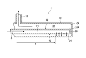
- FIG. 1A is a front sectional view of the combustion heater 1 according to the first embodiment
- FIG. 1B is a side sectional view.
- the combustion heater 1 is supported in a cantilever manner by an outer tube 10 as a heat-resistant metal heat-dissipating tube having a closed end and a supporting means (not shown) on the base end side (left side in FIG. 1A).
- a heat-resistant metal inner pipe 20 having a combustion gas G supply passage 21 therein.
- a gas premixed with fuel and air, or a gas premixed with fuel and oxygen-containing gas can be used, and methane, propane, or the like is used as the fuel.
- the liquid fuel can also be used by providing a location for pre-evaporation.
- the outer pipe 10 has a bottomed cylindrical shape with a closed end, and an exhaust pipe 11 for exhausting the burned gas is connected to the base end side.
- the inner tube 20 has a bottomed cylindrical shape with a closed tip, and a premixed gas supply mechanism (not shown) for supplying the combustion gas G described above is provided on the proximal end side.
- a premixed gas supply mechanism (not shown) for supplying the combustion gas G described above is provided on the proximal end side.
- a total premixed gas having an excess air ratio of about 1.0 to 1.6 is supplied.
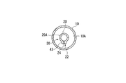
- the inner tube 20 is eccentrically disposed on the inner side of the outer tube 10 on the distal end side, and forms a combustion space 30 between the outer peripheral surface 20A and the inner peripheral surface 10A of the outer tube 10.
- the outer peripheral surface 20 ⁇ / b> A of the inner tube 20 has a first region 22 having the shortest distance from the inner peripheral surface 10 ⁇ / b> A of the outer tube 10 and a second region 23 longer than the first region 22. More specifically, the portion of the outer peripheral surface 20A located in the eccentric direction of the inner tube 20 (downward in FIG. 1, see FIG. 1B) has the largest distance from the inner peripheral surface 10A of the outer tube 10. A short first region (bus bar) 22 is formed along the axial direction, and a second region 23 having a longer distance from the inner peripheral surface 10A than the first region 22 is formed in the other regions.
- a plurality of (here, five) hole portions 24 are spaced from each other along the first region 22 at a position on the distal end side of the inner tube 20. It is formed through.
- An ignition device (not shown) is provided in the vicinity of the position facing the hole 24 of the inner tube 20.
- the outer peripheral surface 20A on the base end side (left side in FIG. 1A) from the region where the hole 24 is formed is a preheating region P for preheating the combustion gas G in the supply passage 21 with the burned gas (flame). It is said that.
- the combustion gas G supplied from the premixed gas supply mechanism to the supply passage 21 of the inner tube 20 is ejected from the hole 24 toward the inner peripheral surface 10A of the outer tube 10.
- the combustion gas G ejected from the hole 24 is opposed to the opposing outer tube.
- the stagnation point S is formed on the inner peripheral surface 10A for each hole 24, and the stagnation point S is used as a boundary to branch off along the inner peripheral surface 10A.
- a flame is formed by igniting the combustion gas G near the stagnation point S by the ignition device. Further, the combustion gas G branched at the stagnation point S flows from the vicinity of the first region 22 having a small cross-sectional area to the combustion space on the opposite side to the first region 22 having a large cross-sectional area, and as shown in FIG. Flames F are formed on both sides of the inner tube 20 of the space 30. At this time, since the flow velocity of the gas at the stagnation point S is zero, the formed flame is stably held by the circulating flow formed around the jet toward the stagnation point S.
- the combustion gas flows through the combustion space 30 and is exhausted from the exhaust pipe 11.
- the combustion gas passes through the wall of the inner pipe 20 in the preheating region P of the inner pipe 20.
- heat exchange with the combustion gas (unburned gas) G is performed.
- the combustion gas G in the supply passage 21 is ejected from the hole 24 in a state of being preheated to a high temperature, and the stability of the flame F is increased. It is possible to burn stably without generating fuel.
- the combustion gas G has a stagnation point S of the combustion gas G formed on the inner peripheral surface 10A of the outer tube 10 and a jet characteristic that forms a circulating flow around the stagnation point S. G is ejected.
- the cost increases as in the case of providing a porous tube. Even when the flow rate is changed, a stable flame F can be easily formed.
- in order to increase the combustion amount it is only necessary to increase the number of holes 24.
- the manufacturing cost of the combustion heater 1 can be suppressed, and the supply pressure of the combustion gas G is greatly increased as in the case of using a porous tube. Even if it is a low-pressure city gas line, it can be applied sufficiently.
- the first region 22 having a short distance between the outer peripheral surface 20A of the inner tube 20 and the inner peripheral surface 10A of the outer tube 10 is arranged with the inner tube 20 eccentric with respect to the outer tube 10. Therefore, it is possible to form and hold the flame F stably and easily at a low cost.
- the flame may reach the outer tube and be unable to be held, and the exhaust path for the burned gas may not be sufficiently secured.
- a sufficient exhaust path can be ensured in the combustion space 30 facing the region (second region) opposite to the first region 22 and in the space where there is no jet between adjacent holes.
- the stagnation point S is formed on the inner peripheral surface 10A of the outer tube 10 and the flame F is also held along the inner peripheral surface 10A. Heating efficiency via the outer tube 10 can be improved without making it difficult to take out heat as in the case of being formed apart.
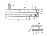
- FIG. 2A is a plan view of the inner tube 20 viewed from the first region 22 side
- FIG. 2B is a side sectional view of the combustion heater 1 in which the inner tube 20 is disposed.
- the tube wall of the inner tube 20 is provided with holes 24 located in the first region 22, and alternately with the holes 24 in the direction along the first region 22.
- Second holes 25 are provided on both sides of the region 22.
- the combustion gas G is ejected from these second holes 25 toward a position away from the stagnation point S.
- the second hole 25 is provided at a position where the combustion gas G ejected from the second hole 25 stably transfers from the flame S formed at the stagnation point S.
- Other configurations are the same as those of the first embodiment.
- the flame F formed and held at the stagnation point S can be transferred to the combustion gas G ejected from the second hole 25, and the flow rate can be easily increased. Gas can be burned in the state. Therefore, in this embodiment, pressure loss does not occur as in the case of using a porous body. Further, it is possible to increase the input heat amount without increasing the length of the inner tube 20 and the outer tube 10 in order to increase the flow rate. As a result, it is possible to prevent an increase in the size of the equipment as in the case where the inner pipe 20 and the outer pipe 10 are lengthened, and the pressure loss can be suppressed, so that it can be used even in a low-pressure city gas line.
- the holes 24 and the second holes 25 are alternately arranged along the first region 22, and the second holes 25 are arranged on both sides of the first region 22. It is possible to form and hold the flame F and to transfer the flame in a stable state with almost equal distribution.
- a support plate (support member) 40 made of a heat-resistant metal or the like is provided along the direction orthogonal to the axial direction on the tip side of the hole portion 24 of the inner tube 20.
- the support plate 40 is fitted and fixed to the outer peripheral surface 20A of the inner tube 20 through the through hole 40A, and is supported on the inner peripheral surface 10A of the outer tube 10 by the outer peripheral surface 40B so as to be movable in the axial direction. Is done. That is, the support plate 40 has a size that closes the entire combustion space 30, is configured integrally with the inner tube 20, and is provided so as to be movable in the axial direction with respect to the outer tube 10.
- the distal end side of the inner tube 20 that is cantilevered on the proximal end side is supported by the support plate 40, whereby the outer peripheral surface 20A of the inner tube 20 (that is, the first region 22). ) And the inner peripheral surface 10A of the outer tube 10 is kept constant. Further, even when the inner tube 20 that is at a high temperature is thermally expanded due to a temperature difference between the outer tube 10 and the inner tube 20, the support plate 40 that is configured integrally with the inner tube 20 is provided inside the outer tube 10. Since it moves relative to the peripheral surface 10A in the axial direction, deformation and distortion are prevented.
- the combustion gas G ejected from the hole 24 located on the most distal side collides with the inner peripheral surface 10A of the opposed outer tube 10, and the stagnation point S on the inner peripheral surface 10A for each hole 24. And is branched along the inner peripheral surface 10A with this stagnation point S as a boundary.
- the combustion space 30 facing the first region 22 is closed by the support plate 40, it is directed toward the support plate 40.
- the combustion gas G branched off in this way is guided to the combustion space 30 facing the first region 22 and the opposite side (second region 23) after colliding with the support plate 40. Therefore, it becomes easy to ignite the surrounding combustion gas G by the flame held at the stagnation point S.
- the combustion space 30 is partitioned by the support plate 40, the combustion gas G stays at the distal end portion of the outer tube 10 at a relatively low temperature, resulting in an unburned state and generating CO. It becomes possible to avoid the situation to do.
- the plate-like support plate 40 is used as the support member.
- the present invention is not limited to this.
- the support member 40 is supported on the inner peripheral surface 10A of the outer tube 10 so as to be movable in the axial direction.
- a support member including a ring member and a rod member that connects the ring member and the inner tube 20 may be used.
- each plate 41 is provided.
- the support plate 41 is provided with a size that closes the combustion space 30 facing the first region 22.
- each support plate 41 has a combustion space like the support plate 40 so that the combustion gas G ejected from the hole 24 flows into the combustion space 30 on the opposite side and can be exhausted from the exhaust pipe 11. Instead of closing the entire region 30, only the combustion space 30 around the first region 22 is blocked.
- Each support plate 41 protrudes from the tube wall of the inner tube 20 toward the outer tube 10 only in the vicinity of the first region 22 so that the position of the inner tube 20 with respect to the outer tube 10 can be maintained.
- it is formed in a fan shape supported by 10A.
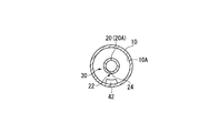
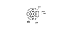
- FIG. 5 is a diagram schematically showing the outer tube 10 and the inner tube 20.
- the inner tube 20 is spaced from the combustion space 30 in the outer tube 10 in the circumferential direction around the central axis of the outer tube 10, respectively.
- Each inner pipe 20 has a hole 24 (not shown in FIG. 5) located in the first region 22 where the outer peripheral face 20A and the inner peripheral face 10A of the outer pipe 10 are the shortest distance. A plurality are formed at intervals in the direction.
- the combustion gas G is ejected from the plurality of inner pipes 20 (holes thereof) to form a stagnation point on the inner peripheral surface 10A of the outer pipe 10.
- a plurality of stable flames are formed around the axis along the inner peripheral surface of the outer tube 10. Therefore, in this embodiment, in addition to obtaining the same operation and effect as the first embodiment, the outer tube 10 can be heated to a higher temperature.
- the present invention is not limited to this, and, for example, shown in the third to fifth embodiments.
- the inner tube 20 may also be configured to provide a second hole in addition to the hole 24.
- the inner tube 20 is eccentrically disposed with respect to the outer tube 10, so that the outer peripheral surface 20 ⁇ / b> A has the shortest distance from the inner peripheral surface 10 ⁇ / b> A of the outer tube 10.
- the present invention is not limited to this.
- the inner tube 20 and the outer tube 10 are arranged concentrically, and a combustion space is formed on the inner peripheral surface 10 ⁇ / b> A of the outer tube 10.
- 30 is provided with a projecting ridge 42 and a hole 24 is provided in the first region 22 facing the ridge 42 and having the shortest distance from the outer peripheral surface 20A, as shown in FIG.
- outer tube 10 are arranged concentrically, and a protrusion 43 is provided on the outer peripheral surface 20A of the inner tube 20 so as to protrude into the combustion space 30 and become the first region 22 with the shortest distance from the inner peripheral surface 10A. It is good also as a structure which provides the hole 24 in 42.
- FIG. 1 A protrusion 43 is provided on the outer peripheral surface 20A of the inner tube 20 so as to protrude into the combustion space 30 and become the first region 22 with the shortest distance from the inner peripheral surface 10A. It is good also as a structure which provides the hole 24 in 42.
- the outer peripheral surface 20A of the inner tube 20 and the inner peripheral surface 10A of the outer tube 10 are not necessarily limited. It is not necessary to form the first region with the shortest distance between them.
- the outer peripheral surface 20A of the inner tube 20 and the inner peripheral surface 10A of the outer tube 10 are arranged at equal intervals. Even if it is a structure, this invention is applicable. In this case, a stagnation point S is formed at a specific position on the inner peripheral surface 10A of the outer tube 10 facing the hole 24 of the inner tube 20, and a circulation flow is formed around the stagnation point S. The flame formed by the circulating flow formed around the jet toward the stagnation point S is stably held, and the same actions and effects as in the above embodiment can be obtained.
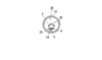
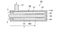
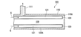
- FIG. 9A is a front sectional view of the combustion heater 101 according to the first embodiment
- FIG. 9B is a side sectional view.
- the combustion heater 101 is supported in a cantilever manner by an outer tube 110 as a heat-resistant metal heat-dissipating tube having a closed end and a supporting means (not shown) on the base end side (left side in FIG. 9A).
- a plurality of refractory metal inner pipes 120 and bluff bodies (stagnation points and circulation flow forming members) 150 having combustion gas G supply passages 121 therein. .
- a gas premixed with fuel and air, or a gas premixed with fuel and oxygen-containing gas can be used, and methane, propane, or the like is used as the fuel.
- the liquid fuel can also be used by providing a location for pre-evaporation.
- the outer pipe 110 has a bottomed cylindrical shape with a closed end, and an exhaust pipe 111 for exhausting the burned gas is connected to the base end side.
- the inner tube 120 has a bottomed cylindrical shape with a closed tip, and a premixed gas supply mechanism (not shown) for supplying the combustion gas G described above is provided on the base end side.
- a premixed gas supply mechanism (not shown) for supplying the combustion gas G described above is provided on the base end side.
- a total premixed gas having an excess air ratio of about 1.0 to 1.6 is supplied.
- a plurality (in this case, six at 60 ° intervals) of the inner tube 20 are arranged at intervals around the central axis of the outer tube 110.
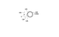
- Each inner tube 120 has a plurality of (in this case, five) hole portions 124 in the radial direction, spaced from each other along the axial direction at a position facing the bluff body 150 on the distal end side and facing the central axis of the outer tube 110. Is formed through the tube wall.
- An ignition device (not shown) is provided in the vicinity of the position facing the hole 124 of the outer tube 110.
- the outer peripheral surface 120A on the base end side (left side in FIG. 9A) from the region where the hole portion 124 is formed is a preheating region P for preheating the combustion gas G in the supply passage 121 with the burned gas (flame). It is said that.
- the bluff body 150 is arranged so that its axis line coincides with the central axis of the outer tube 110 and is surrounded by the inner tube 120, and the inner tube 120 is located at a position facing each inner tube 120 (hole 124).
- a concave curved surface 150A formed around the axis of 120 is formed along the axial direction.
- the combustion gas G supplied from the premixed gas supply mechanism to the supply path 121 of the inner pipe 120 is ejected from the hole 124 toward the concave curved surface 150A of the bluff body 150, as shown in FIG. 9C.
- the combustion gas G ejected from the hole 124 collides with the concave curved surface 150A of the opposing bluff body 150 to form a stagnation point S on the concave curved surface 150A for each hole 124, and the stagnation point S is a boundary. And branching along the concave curved surface 150A.
- the combustion gas flows through the combustion space 130 and is exhausted from the exhaust pipe 111.
- the combustion gas passes through the wall of the inner pipe 120 in the preheating region P of the inner pipe 120.
- heat exchange with the combustion gas (unburned gas) G is performed.
- the combustion gas G in the supply passage 121 is ejected from the hole 124 in a state of being preheated to a high temperature, and the stability of the flame F is increased. It is possible to burn stably without generating fuel.
- the combustion gas G is ejected from the hole 124 formed in the tube wall of the inner tube 120 toward the concave curved surface 150A of the bluff body 150, and the flame F is held at the stagnation point S. Therefore, a stable flame F can be easily formed and maintained even when the flow rate is changed without causing an increase in cost as in the case of providing a porous tube.
- in this embodiment in order to increase the combustion amount, it is only necessary to increase the number of holes 124. Therefore, since there are few components and the structure is simple, the manufacturing cost of the combustion heater 101 can be reduced, and the supply pressure of the combustion gas G is greatly increased as in the case of using a porous tube.
- the flame may reach the outer tube and be unable to be held, and the exhaust path for the burned gas may not be sufficiently secured.
- a sufficient exhaust system path can be secured in the combustion space 130 in the vicinity of the inner peripheral surface 110 ⁇ / b> A of the outer tube 110 and the space where there is no jet between adjacent holes.
- the flow path of the combustion gas G branched at the stagnation point S is along the outer peripheral surface 120A of the inner tube 120, and therefore, smoothly in the vicinity of the inner peripheral surface 110A of the outer tube 110. It becomes possible to exhaust into the combustion space 130.
- the shaft-shaped bluff body is used as the stagnation point and the circulating flow forming member.
- the present invention is not limited to this, and a tubular body (for example, a hexagonal square tube) is used. It is good also as a structure to use.
- a seventh embodiment of the combustion heater 101 will be described with reference to FIG.
- the same components as those of the first embodiment shown in FIG. 6 are denoted by the same reference numerals, and the description thereof is omitted.
- the difference between the seventh embodiment and the first embodiment is that a circular tube similar to the inner tube 20 is arranged on the central axis of the outer tube 110.
- the inner pipe (stagnation point and circulating flow forming member) is aligned with the central axis of the outer pipe 110 and spaced from the inner pipe 120. 220 is arranged.
- the inner tube 220 has a bottomed cylindrical shape with a closed end, and a premixed gas supply mechanism (not shown) for supplying the above-described combustion gas G to the internal supply path 221 is provided on the base end side. Is connected.
- the inner pipe 220 is formed with holes 224 through which the combustion gas G is ejected at positions facing the pipes 120 arranged around the inner pipe 220.
- the hole 224 is formed in a position facing the outer peripheral surface 120 ⁇ / b> A without facing the hole 124 with respect to each inner tube 120 in the axial direction. That is, the hole 124 of the inner tube 120 is also opposed to the outer peripheral surface 220 ⁇ / b> A without facing the hole 224 of the inner tube 220.
- Other configurations are the same as those of the first embodiment.
- the combustion gas G supplied from the premixed gas supply mechanism to the supply passage 121 of the inner tube 120 is ejected from the hole 124 toward the outer peripheral surface 220A of the inner tube 220.
- the A stagnation point S of the combustion gas G is formed on the outer peripheral surface 220A, and the combustion gas G branches at the stagnation point S and flows along the outer peripheral surface 220A.
- the combustion gas G supplied to the supply path 221 of the inner tube 220 is ejected from the hole 224 toward the outer peripheral surface 120A of the inner tube 120, respectively.
- a stagnation point S of the combustion gas G is formed on the outer peripheral surface 120A, and the combustion gas G branches off at the stagnation point S and flows along the outer peripheral surface 120A. That is, in this embodiment, not only the inner tube 220 but also the inner tube 120 acts as a stagnation point and a circulating flow forming member.
- the combustion gas G is also ejected from the inner tube 220, so that heating is performed more effectively.
- the stagnation point S is formed on the outer peripheral surface 120A of the inner pipe 120 disposed in the periphery so that a flame is formed and held, so that a stable flame can be formed and held in a wider range. Can do.
- the hole portion 124 of the inner tube 120 and the hole portion 224 of the inner tube 220 may be provided at positions facing each other.
- the outer peripheral surface 220A is mutually formed.
- 120A is preferably provided at a position opposite to 120A.
- the inner tube is not provided on the central axis of the outer tube 101, and a plurality of inner tubes 120 are spaced apart from each other in the circumferential direction around the central axis (here, 60 ° intervals). 6).
- each inner pipe 120 is provided with a hole portion 124 for injecting the combustion gas G at a position facing the adjacent inner pipe 120.
- the injected combustion gas G is shown in the partially enlarged view of FIG. 10D so as to collide with the outer peripheral surface 120A of the adjacent inner pipe 120.
- it is preferable that the adjacent inner pipes 120 are alternately arranged.
- the stagnation point S and the flame are formed at a position closer to the outer tube 110 as a heat radiating tube. Therefore, it becomes easier to extract heat through the outer tube 110, and the heating efficiency can be improved.
- a support plate (support member) 140 formed of a heat-resistant metal or the like is provided along the direction orthogonal to the axial direction on the tip side of the hole portion 124 of the inner tube 120. 12B, the support plate 140 is fitted and fixed to the outer peripheral surface 120A of the inner tube 120 and the outer peripheral surface 150A of the bluff body 150, and the outer peripheral surface 140B is axially connected to the inner peripheral surface 110A of the outer tube 110. It is supported movably. That is, the support plate 140 has a size that closes the entire combustion space 130, is integrally formed with the inner tube 120 and the bluff body 150, and is provided so as to be movable in the axial direction with respect to the outer tube 110. Yes.
- the inner pipe 120 and the front end side of the bluff body 150 that are cantilevered on the base end side are supported by the support plate 140, whereby the outer peripheral surface 120 ⁇ / b> A and the bluff of the inner pipe 120 are supported.
- the distance between the outer peripheral surface 150A of the body 150 and the inner peripheral surface 110A of the outer tube 110 is kept constant. Further, even when the inner tube 120 that is at a high temperature is thermally expanded due to a temperature difference between the outer tube 110 and the inner tube 120, the support plate 140 that is integrally formed with the inner tube 120 and the bluff body 150 is not removed. Since the tube 110 moves relative to the inner peripheral surface 110A of the tube 110 in the axial direction, deformation and distortion are prevented.
- the combustion gas G ejected from the hole 124 located on the most distal side collides with the outer peripheral surface 150 ⁇ / b> A of the opposing bluff body 150, and for each hole 124.
- the stagnation point S is formed on the outer peripheral surface 150A, and is branched along the outer peripheral surface 150A with the stagnation point S as a boundary.
- the combustion space 130 facing the hole 124 is blocked by the support plate 140. Therefore, the combustion gas G branched toward the support plate 140 is guided to the combustion space 130 on the opposite side to the bluff body 150 after colliding with the support plate 140. Therefore, it becomes easy to ignite the surrounding combustion gas G by the flame held at the stagnation point S.
- the combustion gas G stays at the distal end portion of the outer tube 110 at a relatively low temperature and becomes unburned to generate CO. It becomes possible to avoid the situation to do.
- the plate-like support plate 140 is used as the support member.
- the support member 140 is supported on the inner peripheral surface 110A of the outer tube 110 so as to be movable in the axial direction.
- a support member including a ring member and a rod member that connects the ring member and the inner tube 120 and the bluff body 150 may be used.
- 7th Embodiment shown in FIG. It is good also as a structure which provides a support plate in the inner tube
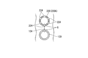
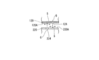
- FIG. 13A is a plan view of the inner tube 120 as viewed from the side of the bluff body 150 (the central axis of the outer tube 10; see FIG. 9), and FIG. 13B is a side sectional view.
- the tube wall (outer peripheral surface 120 ⁇ / b> A) of the inner tube 120 is provided with a hole 124 at an axial position 122 facing the central axis of the outer tube 110, and a hole is formed in a direction along the axial position 122.
- a second hole 125 is provided alternately with the portion 124 and on both sides of the shaft position 122.
- the combustion gas G is ejected from these second holes 125 toward a position away from the stagnation point S.
- the second hole 125 is provided at a position where the combustion gas G ejected from the second hole 125 stably transfers from the flame S formed at the stagnation point S.
- Other configurations are the same as those in the sixth embodiment.
- the flame formed and held at the stagnation point S can be transferred to the combustion gas G ejected from the second hole 125, and the flow rate is easily increased. Can burn gas. Therefore, in this embodiment, pressure loss does not occur as in the case of using a porous body. Further, it is possible to increase the input heat amount without increasing the length of the inner pipe 120, the bluff body 150, and the outer pipe 110 in order to increase the flow rate. As a result, it is possible to prevent an increase in the size of the device as when the inner tube 120, the bluff body 150, and the outer tube 110 are lengthened. Moreover, since pressure loss can be suppressed, it can also be used in low-pressure city gas lines.
- the holes 124 and the second holes 125 are alternately arranged along the axial position 122, and the second holes 125 are arranged on both sides of the axial position 122. It is possible to cause formation and maintenance and flame transfer in a stable state with almost equal distribution.
- the configuration in which the second hole 125 is provided in addition to the hole 124 in the combustion heater 101 shown in the sixth embodiment is not limited to this.
- the inner tube 120 (inner tube 220) shown in the seventh to ninth embodiments may also be configured to provide the second hole portion in addition to the hole portion 124.
- the stagnation point and the bluff body 150 which is a circulating flow forming member are disposed concentrically with the outer tube 110, and a plurality of inner tubes 20 are disposed around the central axis of the outer tube 110.
- the configuration is not limited to this, and the inner tube 20 may be disposed concentrically with the outer tube 110, and a plurality of bluff bodies 150 may be disposed around the central axis of the outer tube 110. Even with this configuration, it is possible to obtain the same operations and effects as in the sixth embodiment.
- a flame can be stably formed without incurring an increase in cost, and the heating efficiency of the combustion heater can be improved.
Landscapes
- Engineering & Computer Science (AREA)
- Chemical & Material Sciences (AREA)
- Combustion & Propulsion (AREA)
- Mechanical Engineering (AREA)
- General Engineering & Computer Science (AREA)
- Gas Burners (AREA)
- Combustion Of Fluid Fuel (AREA)
- Spray-Type Burners (AREA)
Abstract
Description
別途保炎機構を設けることなく、予混合ガスの流速と燃焼速度を釣り合わせ続けることは困難である。また多孔質体から流出する予混合ガスは、位置により流速・流量にばらつきがあり、安定した管状火炎の形成が困難である。
また、管状火炎が放熱管から離間した位置に形成されることから、放熱管を介して熱を取り出しにくく、加熱効率が低下する可能性もある。
さらに、上記の技術は、内管の一部に多孔質管を設ける必要があるため、製造に手間がかかりコストアップを招くという問題もある。
本発明の燃焼加熱器は、内部に燃焼用ガスの供給路を有する内管と、内管の外周に燃焼空間を隔てて配置された外管とを有し、前記燃焼用ガスを噴出する孔部が前記内管の管壁に形成された燃焼加熱器である。そして、前記燃焼空間に前記燃焼用ガスのよどみ点を形成し、かつ前記よどみ点の周囲に循環流を形成するよう、前記燃焼空間における前記燃焼用ガスの流れが定められている。
本発明の燃焼加熱器は、内部に燃焼用ガスの供給路を有する内管と、内管の外周に燃焼空間を隔てて配置された外管とを有し、前記燃焼用ガスを噴出する孔部が前記内管の管壁に形成された燃焼加熱器である。そして、前記外管の内周面上に、前記燃焼用ガスのよどみ点を形成するとともに、よどみ点の周囲に循環流を形成する噴出特性で前記燃焼用ガスが噴出される。
上記噴出特性を有する燃焼加熱器では、流速がゼロに近いよどみ点周辺の燃焼用ガスに点火(着火)することにより、容易に(すなわち、コストアップを招くことなく)安定した火炎を形成して保持することができる。また、よどみ点周りに循環流が形成されるため、安定な燃焼を実現することができる。従来では、ガスの流量が大きくなると、燃焼ガスの排気経路を十分に確保できないとともに、火炎の安定性が低下する可能性があるが、本発明では外管の内周面に火炎を安定して形成・保持することができる。
前記内管と前記外管とは同心で配置され、前記孔部が、前記外管の内周面上の特定位置に前記よどみ点を形成する位置に配置される場合には、外管の内周面上の特定位置に火炎を安定して形成・保持することができる。
また、前記内管の外周面が、前記外管の内周面との距離が最も短い第1領域と、前記第1領域よりも長い第2領域とを有し、外管の内周面との距離が短い第1領域に孔部を形成した場合には、第1領域と逆側の領域を含む第2領域と外管の内周面との間に燃焼ガスの排気経路を確保することが可能になる。
さらに、本発明では、外管の内周面のよどみ点に火炎が形成・保持されることから、外管を介して効率的に加熱することが可能になる。
なお、課題を解決するための手段における以下の説明は、内管が外管に対して偏心して配置される場合についてのものである。
前記内管の中心軸周りに、周方向に間隔をあけて複数配設する構成も好適に採用できる。
これにより、本発明では、外管の内周面に対して周方向に間隔をあけて複数火炎を形成・保持することが可能になり、より効果的に加熱することが可能になる。
これにより、本発明では、よどみ点に形成・保持された火炎を第2孔部から噴出した燃焼用ガスに火移りさせることが可能になる。そのため、本発明では、多孔質体を用いる場合のように圧力損失が生じない。また内管及び外管を長くすることなく、投入熱量を増加させることが可能になり、内管及び外管を長くした場合のような機器の大型化を防ぐことが可能になる。そして、本発明では、圧力損失を抑えることができるため、低圧の都市ガスラインでも使用可能となる。
これにより、本発明では、火炎の形成・保持及び火炎の火移りを等分布で生じさせることが可能になる。
これにより、本発明では、内管の先端部に振れが生じ、基端側と先端側とで内管の外周面と外管の内周面との間隔が一定にならなくなることを防止して、孔部が形成された第1領域と外管の内周面との間隔を一定に保持することが可能になる。そのため、よどみ点を安定して継続的に形成することができ、結果として安定、且つ継続的に火炎を形成・保持することが可能になる。
これにより、本発明では、最も先端側に位置する孔部から噴出され先端側へ向かう燃焼用ガスが支持部材に衝突して、第2領域側の燃焼空間に導かれる。そのため、よどみ点の火炎も第2領域側の燃焼空間に導かれ、この燃焼空間の燃焼用ガスを着火させやすくすることができる。
これにより、本発明では、各孔部から噴出された燃焼用ガスが第2領域側の燃焼空間に導かれる。そのため、よどみ点の火炎も第2領域側の燃焼空間に導かれ、この燃焼空間の燃焼用ガスを一層着火させやすくすることができる。
本発明の燃焼加熱器は、内部に燃焼用ガスの供給路を有する内管と、内管の外周に燃焼空間を隔てて配置された外管とを有し、前記燃焼用ガスを噴出する孔部が前記内管の管壁に形成された燃焼加熱器である。この燃焼加熱器は、前記燃焼空間に軸方向に沿って前記孔部と対向して設けられ、前記孔部から噴出された前記燃焼用ガスのよどみ点および循環流を形成するよどみ点および循環流形成部材を有する。
上記構造を有する燃焼加熱器では、よどみ点および循環流形成部材の表面に形成され流速がゼロに近いよどみ点周辺の燃焼用ガスに点火(着火)することにより、容易に(すなわち、コストアップを招くことなく)安定した火炎を形成して保持することができる。また、よどみ点周りに循環流が形成されるため、安定な燃焼を実現することができる。従来では、ガスの流量が大きくなると、燃焼ガスの排気経路を十分に確保できないとともに、火炎の安定性が低下する可能性があるが、本発明では孔部と対向するよどみ点および循環流形成部材の表面に火炎を安定して形成・保持することができるとともに、内管とよどみ点および循環流形成部材とが対向しない領域に燃焼ガスの排気経路を確保することが可能になる。
これにより、本発明では、外管の中心軸周りに燃焼用ガスのよどみ点及び火炎を安定して形成・保持することが可能になり、温度分布を抑制しつつ外管を加熱することができる。
これにより、外管の中心に配されたよどみ点および循環流形成部材の表面に加えて、中心軸周りに複数配置された内管の表面にも燃焼用ガスのよどみ点及び火炎を安定して形成・保持することが可能になる。
これにより、複数の内管について、隣り合う内管の孔部と対向する外周面に燃焼用ガスのよどみ点及び火炎を安定して形成・保持することが可能になる。
これにより、本発明では、外管の中心軸周りに燃焼用ガスのよどみ点及び火炎を安定して形成・保持することが可能になり、温度分布を抑制しつつ外管を加熱することができる。
これにより、本発明では、よどみ点に形成・保持された火炎を第2孔部から噴出した燃焼用ガスに火移りさせることが可能になる。そのため、本発明では、多孔質体を用いる場合のように圧力損失が生じない。また内管及び外管を長くすることなく、投入熱量を増加させることが可能になり、内管及び外管を長くした場合のような機器の大型化を防ぐことが可能になる。そして、本発明では、圧力損失を抑えることができるため、低圧の都市ガスラインでも使用可能となる。
これにより、本発明では、火炎の形成・保持及び火炎の火移りを等分布で生じさせることが可能になる。
これにより、本発明では、内管及びよどみ点および循環流形成部材の先端部に振れが生じ、基端側と先端側とで内管及びよどみ点および循環流形成部材の外周面と外管の内周面との間隔が一定にならなくなることを防止して、孔部及びよどみ点および循環流形成部材と外管の内周面との間隔を一定に保持することが可能になる。そのため、よどみ点を安定して継続的に形成することができ、結果として安定、且つ継続的に火炎を形成・保持することが可能になる。
これにより、本発明では、最も先端側に位置する孔部から噴出され先端側へ向かう燃焼用ガスが支持部材に衝突して、幅広の燃焼空間に導かれる。そのため、よどみ点の火炎もこの燃焼空間に導かれ、この燃焼空間の燃焼用ガスを着火させやすくすることができる。
これにより、本発明では、低温の外管先端部に燃焼用ガスが滞留し未燃状態となってCOが生じたりする事態を回避することが可能になる。
これにより、本発明では、外管と内管の温度差により、特に軸方向に熱膨張量に大きな差が生じた場合でも、支持板が外管に相対移動するため、支持板に変形等が生じることなく、内管の外周面と外管の内周面との間隔を保持することが可能になる。
これにより、本発明では、基端側から燃焼用ガスを供給するとともに、排気ガスを排気できる小型で低価格の燃焼加熱器を実現することができる。
図1Aは、第1実施形態に係る燃焼加熱器1の正面断面図であり、図1Bは側面断面図である。
燃焼加熱器1は、先端が閉塞された耐熱金属製の放熱管としての外管10と、基端側(図1Aの左側)で図示しない支持手段により片持ちで支持されて外管10の内部に配設され、内部に燃焼用ガスGの供給路21を有する耐熱金属製の内管20とから概略構成されている。
この内管20は、先端側において外管10の内側に偏心して配置され、外周面20Aと外管10の内周面10Aとの間に燃焼空間30を形成する。
なお、孔部24が形成された領域よりも基端側(図1Aでは左側)の外周面20Aは、燃焼したガス(火炎)により供給路21の燃焼用ガスGを予熱するための予熱領域Pとされている。
予混合気供給機構から内管20の供給路21に供給された燃焼用ガスGは、孔部24から外管10の内周面10Aに向けて噴出される。
ここで、孔部24は外管10の内周面10Aとの距離が最も短い第1領域22に形成されていることから、孔部24から噴出された燃焼用ガスGは、対向する外管10の内周面10Aと衝突し、各孔部24毎に内周面10A上によどみ点Sを形成し、このよどみ点Sを境として内周面10Aに沿って分岐される。
このとき、よどみ点Sにおけるガスの流速はゼロであるため、また、よどみ点Sに向かう噴流周囲に形成される循環流により、形成した火炎は安定して保持される。
これにより、供給路21における燃焼用ガスGは、高温に予熱された状態で孔部24から噴出することになり、火炎Fの安定性が増し、狭隘な燃焼空間30に噴出されても、未燃分を生じさせることなく、安定に燃焼することができる。
加えて、本実施形態では、燃焼量を増加させるためには、孔部24の数を増やすだけで済む。従って、構成部品も少なく、構造もシンプルであることから、燃焼加熱器1の製造コストも抑えることができるとともに、多孔質管を用いた場合のように、燃焼用ガスGの供給圧を大幅に上げる必要もなく、低圧の都市ガスラインであっても十分に適用可能になる。さらに、本実施形態では、内管20の外周面20Aと、外管10の内周面10Aとの距離が短い第1領域22を、外管10に対して内管20を偏心させて配置するという簡単な構成で形成しているため、容易、且つ低コストで安定して火炎Fを形成・保持することが可能になる。
続いて、燃焼加熱器1の第2実施形態について図2を参照して説明する。
なお、この図において、図1に示す第1実施形態の構成要素と同一の要素については同一符号を付し、その説明を省略する。
第2の実施の形態と上記の第1の実施の形態とが異なる点は、孔部24とは別に、ガスの圧力損失を低下させるための第2孔部を設けたことである。
図2Aに示すように、内管20の管壁には、第1領域22に位置して孔部24が設けられるとともに、第1領域22に沿う方向に孔部24と交互に、且つ第1領域22を挟んだ両側に位置して第2孔部25が設けられている。
これら第2孔部25からは、図2Bに示すように、よどみ点Sから離間した位置に向けて燃焼ガスGが噴出される。
また、第2孔部25は、第2孔部25から噴出された燃焼用ガスGによどみ点Sで形成された火炎Sから安定して火移りする位置に設けられる。
他の構成は、上記第1実施形態と同様である。
また、本実施形態では、孔部24と第2孔部25とが第1領域22に沿って交互に、また第2孔部25が第1領域22を挟んだ両側に配置されることから、火炎Fの形成・保持及び火炎の火移りをほぼ等分布で安定した状態で生じさせることが可能になる。
続いて、燃焼加熱器1の第3実施形態について図3を参照して説明する。
なお、この図において、図1に示す第1実施形態の構成要素と同一の要素については同一符号を付し、その説明を省略する。
第3の実施形態と上記の第1実施形態とが異なる点は、内管20の先端側に支持板を設けたことである。
すなわち、支持板40は、燃焼空間30の全体を閉塞する大きさを有して内管20と一体的に構成され、外管10に対して軸方向に移動自在に設けられている。
なお、上記実施形態では、支持部材として板状の支持板40を用いる構成としたが、これに限定されるものではなく、例えば外管10の内周面10Aに軸方向に移動自在に支持されたリング部材と、このリング部材と内管20とを連結するロッド部材とからなる支持部材を用いてもよい。
続いて、上記第3実施形態の変形例としての第4実施形態について、図4を参照して説明する。
なお、この図において、図3に示す第3実施形態の構成要素と同一の要素については同一符号を付し、その説明を省略する。
続いて、燃焼加熱器1の第5実施形態について、図5を参照して説明する。
図5は、外管10及び内管20を模式的に示した図である。
この図に示すように、本実施形態における燃焼加熱器1においては、内管20が外管10内の燃焼空間30に、外管10の中心軸周りに周方向に間隔をあけて、且つそれぞれが外管10と偏心して複数(図5では、60°間隔で6つ)配置されている。
また、各内管20には、外周面20Aと外管10の内周面10Aとが最も短い距離となる第1領域22に位置して、孔部24(図5では図示せず)が軸方向に間隔をあけて複数形成されている。
従って、本実施形態では、上記第1実施形態と同様の作用・効果が得られることに加えて、より高温に外管10を加熱することが可能になる。
(第6実施形態)
図9Aは、第1実施形態に係る燃焼加熱器101の正面断面図であり、図9Bは側面断面図である。
燃焼加熱器101は、先端が閉塞された耐熱金属製の放熱管としての外管110と、基端側(図9Aの左側)で図示しない支持手段により片持ちで支持されて外管110の内部の燃焼空間130に配設され、内部に燃焼用ガスGの供給路121を有する耐熱金属製の複数の内管120及びブラフボディ(よどみ点および循環流形成部材)150とから概略構成されている。
この内管20は、図9Bに示すように、外管110の中心軸周りに複数(ここでは60°間隔で6つ)互いに間隔をあけて配置される。
なお、孔部124が形成された領域よりも基端側(図9Aでは左側)の外周面120Aは、燃焼したガス(火炎)により供給路121の燃焼用ガスGを予熱するための予熱領域Pとされている。
予混合気供給機構から内管120の供給路121に供給された燃焼用ガスGは、図9Cに示すように、それぞれ孔部124からブラフボディ150の凹曲面150Aに向けて噴出される。
孔部124から噴出された燃焼用ガスGは、対向するブラフボディ150の凹曲面150Aと衝突し、各孔部124毎に凹曲面150A上によどみ点Sを形成し、このよどみ点Sを境として凹曲面150Aに沿って分岐される。
そして、よどみ点Sで分岐した燃焼用ガスGは、ガス圧が高いブラフボディ150の近傍から、内管120に対してブラフボディ150と逆側である外管110の内周面110A側の燃焼空間130に流れる。
これにより、供給路121における燃焼用ガスGは、高温に予熱された状態で孔部124から噴出することになり、火炎Fの安定性が増し、狭隘な燃焼空間130に噴出されても、未燃分を生じさせることなく、安定に燃焼することができる。
特に、本実施形態では、よどみ点Sで分岐した燃焼用ガスGの流路が、内管120の外周面120Aに沿ったものとなるため、円滑に外管110の内周面110Aの近傍の燃焼空間130に排気することが可能になる。
なお、本実施形態では、よどみ点および循環流形成部材として軸状のブラフボディを用いる構成としたが、これに限定されるものではなく、管体(円管や例えば六角形の角管)を用いる構成としてもよい。
続いて、燃焼加熱器101の第7実施形態について図10を参照して説明する。
なお、この図において、図6に示す第1実施形態の構成要素と同一の要素については同一符号を付し、その説明を省略する。
第7の実施の形態と上記の第1の実施の形態とが異なる点は、外管110の中心軸上に内管20と同様の円管を配置したことである。
他の構成は、上記第1実施形態と同様である。
そして、よどみ点Sで分岐した燃焼用ガスGは、ガス圧が相対的に低い外管110の内周面110A側の燃焼空間130に流れる。燃焼したガスは、排気管111から排気される。
なお、内管120の孔部124と、内管220の孔部224とは、互いに対向する位置に設けてもよいが、よどみ点Sをより安定して形成するためには、互いに外周面220A、120Aに対向する位置に設けることが好ましい。
続いて、燃焼加熱器1の第8実施形態について図11を参照して説明する。
なお、この図において、図9に示す第1実施形態の構成要素と同一の要素については同一符号を付し、その説明を省略する。
各内管120には、図11Cの部分拡大図に示すように、隣り合う内管120と対向する位置にそれぞれ燃焼用ガスGを噴出する孔部124が設けられている。
また、孔部124の軸方向の位置については、第7実施形態と同様に、噴出した燃焼用ガスGが隣り合う内管120の外周面120Aに衝突するように、図10Dの部分拡大図に示したように、隣り合う内管120同士で互い違いになるように配置することが好ましい。
続いて、燃焼加熱器101の第9実施形態について図12を参照して説明する。
なお、この図において、図9に示す第6実施形態の構成要素と同一の要素については同一符号を付し、その説明を省略する。
第9の実施形態と上記の第6実施形態とが異なる点は、内管120及びブラフボディ150の先端側に支持板を設けたことである。
すなわち、支持板140は、燃焼空間130の全体を閉塞する大きさを有して内管120及びブラフボディ150と一体的に構成され、外管110に対して軸方向に移動自在に設けられている。
また、上記実施形態では、第6実施形態で示した内管120及びブラフボディ150に支持板140を設ける構成としたが、これに限定されるものではなく、図10に示した第7実施形態における内管120、220に支持板を設ける構成や、図11に示した第3実施形態における内管120に支持板を設ける構成としてもよい。
これにより、第9実施形態と同様の作用・効果を奏することができる。
続いて、燃焼加熱器1の第10実施形態について図13を参照して説明する。
第10実施形態と上記の第6実施形態とが異なる点は、孔部124とは別に、ガスの圧力損失を低下させるための第2孔部を設けたことである。
図13Aに示すように、内管120の管壁(外周面120A)には、外管110の中心軸と対向する軸位置122に孔部124が設けられるとともに、軸位置122に沿う方向に孔部124と交互に、且つ軸位置122を挟んだ両側に位置して第2孔部125が設けられている。
これら第2孔部125からは、図13Bに示すように、よどみ点Sから離間した位置に向けて燃焼ガスGが噴出される。
また、第2孔部125は、第2孔部125から噴出された燃焼用ガスGによどみ点Sで形成された火炎Sから安定して火移りする位置に設けられる。
他の構成は、上記第6実施形態と同様である。
また、本実施形態では、孔部124と第2孔部125とが軸位置122に沿って交互に、また第2孔部125が軸位置122を挟んだ両側に配置されることから、火炎の形成・保持及び火炎の火移りをほぼ等分布で安定した状態で生じさせることが可能になる。
Claims (19)
- 内部に燃焼用ガスの供給路を有する内管と、内管の外周に燃焼空間を隔てて配置された外管とを有し、前記燃焼用ガスを噴出する孔部が前記内管の管壁に形成された燃焼加熱器であって、
前記燃焼空間に前記燃焼用ガスのよどみ点を形成し、かつ前記よどみ点の周囲に循環流を形成するよう、前記燃焼空間における前記燃焼用ガスの流れが定められている燃焼加熱器。 - 内部に燃焼用ガスの供給路を有する内管と、この内管の外周に燃焼空間を隔てて配置された外管とを有し、前記燃焼用ガスを噴出する孔部が前記内管の管壁に形成された燃焼加熱器であって、
前記外管の内周面上に前記燃焼用ガスのよどみ点を形成するとともに、よどみ点の周囲に循環流を形成する噴出特性で前記燃焼用ガスが噴出される燃焼加熱器。 - 前記内管と前記外管とは同心で配置され、
前記孔部は、前記外管の内周面上の特定位置に前記よどみ点を形成する位置に配置される請求項2に記載の燃焼加熱器。 - 前記内管の外周面は、前記外管の内周面との距離が最も短い第1領域と、前記第1領域よりも長い第2領域とを有し、
前記孔部は、前記第1領域に配置されて前記外管の内周面上に前記燃焼用ガスのよどみ点を形成する請求項2に記載の燃焼加熱器。 - 前記内管は、前記外管に対して偏心した位置に配置され、
前記孔部は、前記内管の偏心方向に位置する外周面に形成される請求項4に記載の燃焼加熱器。 - 前記内管は、前記外管の中心軸周りに、周方向に間隔をあけて複数配設される請求項5に記載の燃焼加熱器。
- 前記内管には、前記第1領域から外れた位置に配置され、前記よどみ点と離間した位置に前記燃焼用ガスを噴出する第2孔部が設けられるとともに、前記第2孔部は、前記第1領域を挟んだ両側に、前記第1領域に沿う方向に前記孔部と交互に配置される請求項4に記載の燃焼加熱器。
- 基端側で片持ち支持された前記内管の先端側をこの内管と前記外管との間で支持して、前記内管の外周面と前記外管の内周面との間隔を保持する支持部材を有する請求項4に記載の燃焼加熱器。
- 前記孔部は、前記第1領域に間隔をあけて複数配列され、
前記支持部材は、前記孔部のそれぞれに対応するよどみ点を挟む配列方向の両側に、それぞれ前記第1領域と対向する前記燃焼空間を閉塞する大きさで設けられる請求項8に記載の燃焼加熱器。 - 最も先端側に位置する前記孔部よりも先端側に配置された前記支持部材は、前記燃焼空間全体を閉塞する大きさで設けられる請求項8に記載の燃焼加熱器。
- 内部に燃焼用ガスの供給路を有する内管と、この内管の外周に燃焼空間を隔てて配置された外管とを有し、前記燃焼用ガスを噴出する孔部が前記内管の管壁に形成された燃焼加熱器であって、
前記燃焼空間に軸方向に沿って前記孔部と対向して設けられ、前記孔部から噴出された前記燃焼用ガスのよどみ点および循環流を形成するよどみ点および循環流形成部材を有する燃焼加熱器。 - 前記よどみ点および循環流形成部材は、前記外管の中心軸上に配置され、
前記内管は、前記孔部を前記中心軸に向けて、前記中心軸周りに複数配置される請求項11に記載の燃焼加熱器。 - 前記よどみ点および循環流形成部材は、前記内管の軸周りに形成された凹曲面を前記複数の内管毎に有する請求項12に記載の燃焼加熱器。
- 前記よどみ点および循環流形成部材は、内部に前記燃焼用ガスの供給路を有するとともに、前記中心軸周りに複数配置された前記内管の各外周面に向けて前記燃焼用ガスを噴出してよどみ点を形成する前記孔部をそれぞれ有する請求項12に記載の燃焼加熱器。
- 前記よどみ点および循環流形成部材は、前記燃焼空間に互いに間隔をあけて複数設けられ、それぞれが隣り合う前記内管の外周面に対向して前記孔部が形成された前記内管である請求項11に記載の燃焼加熱器。
- 前記内管は、前記外管の中心軸周りに互いに間隔をあけて複数配置される請求項15に記載の燃焼加熱器。
- 前記内管には、前記よどみ点と離間した位置に前記燃焼用ガスを噴出する第2孔部が設けられるとともに、前記第2孔部は、前記よどみ点および循環流形成部材と対向する領域を挟んだ両側に、前記対向する領域に沿う方向に前記孔部と交互に配置される請求項11に記載の燃焼加熱器。
- 基端側で片持ち支持された前記内管及び前記よどみ点および循環流形成部材の先端側を前記外管との間で支持して、前記内管及び前記よどみ点および循環流形成部材の外周面と前記外管の内周面との間隔を保持する支持部材を有する請求項11に記載の燃焼加熱器。
- 最も先端側に位置する前記孔部よりも先端側に配置された前記支持部材は、前記燃焼空間全体を閉塞する大きさで設けられる請求項18に記載の燃焼加熱器。
Priority Applications (5)
| Application Number | Priority Date | Filing Date | Title |
|---|---|---|---|
| CA2713030A CA2713030C (en) | 2008-02-01 | 2009-01-30 | Combustion heater |
| CN2009801034727A CN101932879B (zh) | 2008-02-01 | 2009-01-30 | 燃烧加热器 |
| BRPI0906723A BRPI0906723A2 (pt) | 2008-02-01 | 2009-01-30 | aquecedor de combustão |
| EP09706786.2A EP2249082B1 (en) | 2008-02-01 | 2009-01-30 | Combustion heater |
| US12/812,889 US9625147B2 (en) | 2008-02-01 | 2009-01-30 | Combustion heater |
Applications Claiming Priority (4)
| Application Number | Priority Date | Filing Date | Title |
|---|---|---|---|
| JP2008022974A JP5182617B2 (ja) | 2008-02-01 | 2008-02-01 | 燃焼加熱器 |
| JP2008-022975 | 2008-02-01 | ||
| JP2008022975A JP5182618B2 (ja) | 2008-02-01 | 2008-02-01 | 燃焼加熱器 |
| JP2008-022974 | 2008-02-01 |
Publications (1)
| Publication Number | Publication Date |
|---|---|
| WO2009096562A1 true WO2009096562A1 (ja) | 2009-08-06 |
Family
ID=40912904
Family Applications (1)
| Application Number | Title | Priority Date | Filing Date |
|---|---|---|---|
| PCT/JP2009/051654 Ceased WO2009096562A1 (ja) | 2008-02-01 | 2009-01-30 | 燃焼加熱器 |
Country Status (9)
| Country | Link |
|---|---|
| US (1) | US9625147B2 (ja) |
| EP (1) | EP2249082B1 (ja) |
| KR (1) | KR101215091B1 (ja) |
| CN (1) | CN101932879B (ja) |
| BR (1) | BRPI0906723A2 (ja) |
| CA (1) | CA2713030C (ja) |
| RU (1) | RU2454604C2 (ja) |
| TW (1) | TW200940908A (ja) |
| WO (1) | WO2009096562A1 (ja) |
Families Citing this family (7)
| Publication number | Priority date | Publication date | Assignee | Title |
|---|---|---|---|---|
| WO2010067595A1 (ja) * | 2008-12-10 | 2010-06-17 | 株式会社Ihi | 燃焼器 |
| JP5961941B2 (ja) * | 2011-07-27 | 2016-08-03 | 株式会社Ihi | 密閉式ガスヒータおよび密閉式ガスヒータを用いた連続加熱炉 |
| CN106359490A (zh) * | 2016-10-25 | 2017-02-01 | 张文翰 | 一种用于隧道式烘干加热炉的高效节能双管催化燃烧器 |
| US11112120B2 (en) * | 2019-12-18 | 2021-09-07 | Warming Trends, Llc | Artificial log assembly |
| CN112191698B (zh) * | 2020-09-29 | 2023-01-24 | 太原科技大学 | 一种用于热轧h型钢高压水除鳞装置 |
| US20240280269A1 (en) * | 2021-06-17 | 2024-08-22 | Warming Trends, Llc | Artificial log assembly |
| CN116066824B (zh) * | 2023-03-22 | 2025-07-25 | 广州文冲船舶修造有限公司 | 一种风灯头及加温风灯装置 |
Citations (6)
| Publication number | Priority date | Publication date | Assignee | Title |
|---|---|---|---|---|
| JPS53146337A (en) * | 1977-05-26 | 1978-12-20 | Ishikawajima Harima Heavy Ind Co Ltd | Pilot burner |
| JPH02150608A (ja) * | 1988-11-29 | 1990-06-08 | Toho Gas Co Ltd | チューブバーナ |
| JPH0590119U (ja) * | 1992-04-15 | 1993-12-07 | 東邦瓦斯株式会社 | チューブバーナの内部燃焼装置 |
| JPH06229522A (ja) * | 1993-02-02 | 1994-08-16 | Toho Gas Co Ltd | ラジアントチューブバーナ |
| JPH06241419A (ja) | 1993-02-17 | 1994-08-30 | Toho Gas Co Ltd | 環状火炎式のラジアントチューブバーナ |
| JPH08315656A (ja) * | 1995-05-18 | 1996-11-29 | Hitachi Cable Ltd | 熱風循環式横型エナメル線焼付炉 |
Family Cites Families (50)
| Publication number | Priority date | Publication date | Assignee | Title |
|---|---|---|---|---|
| US782735A (en) * | 1904-10-04 | 1905-02-14 | Carl Eickemeyer | Gas-heater. |
| US1735945A (en) * | 1927-08-05 | 1929-11-19 | Wollaston Thomas Roland | Boiler and the like |
| GB502112A (en) | 1937-09-15 | 1939-03-13 | Gibbons Brothers Ltd | Improvements in gas or oil fired heating elements or radiants |
| US2539512A (en) * | 1946-11-15 | 1951-01-30 | Herbert William Charles | Tubular gas burner with attached reflector |
| US2478732A (en) * | 1948-04-01 | 1949-08-09 | Wilson | Combustion tube heating apparatus |
| US2632503A (en) * | 1948-04-27 | 1953-03-24 | Standard Oil Dev Co | Tubular radiant gas burner |
| US2869630A (en) * | 1954-04-28 | 1959-01-20 | John H Flynn | Gas burner with selective flame distribution |
| US3217701A (en) * | 1961-07-17 | 1965-11-16 | American Thermocatalytic Corp | Radiant heater |
| US3220401A (en) * | 1962-05-21 | 1965-11-30 | Hazen Engineering Company | Radiant heating units |
| NL297359A (ja) * | 1962-08-30 | |||
| US3187740A (en) * | 1963-04-10 | 1965-06-08 | Hazen Engineering Company | Radiant tube heaters |
| US3229747A (en) * | 1963-09-18 | 1966-01-18 | William P Ayers | Radiant burner |
| US3174474A (en) | 1963-10-04 | 1965-03-23 | Hazen Engineering Company | Radiant heating units |
| US3334820A (en) * | 1964-01-23 | 1967-08-08 | John H Flynn | Gas burner of selective flame distribution type |
| SU424893A1 (ru) * | 1970-10-01 | 1974-04-25 | Н. Т. Колца, А. М. Семернин, В. Д. Брук , А. Е. Еринов | ТУПИКОВАЯ РАДИАЦИОННАЯ ТРУБАВПТБ•-r.vrs gufvarpTngVJii^ Oovm--.! :JlJ |
| US3688760A (en) * | 1970-12-09 | 1972-09-05 | Bloom Eng Co Inc | Radiant tube assembly |
| JPS6030672Y2 (ja) * | 1982-03-07 | 1985-09-13 | 日東工器株式会社 | 太陽熱コレクタ |
| JPS61147009A (ja) | 1984-12-19 | 1986-07-04 | Toshiba Ceramics Co Ltd | ラジアントチユ−ブ |
| DE3509521A1 (de) * | 1985-03-16 | 1986-09-25 | Hans Dr.h.c. 3559 Battenberg Vießmann | Atmosphaerischer gasbrenner |
| JPS61272517A (ja) | 1985-05-28 | 1986-12-02 | Toshiba Ceramics Co Ltd | ラジアントチユ−ブ |
| US4809672A (en) * | 1987-10-13 | 1989-03-07 | Alzeta Corporation | Gas-fired bayonet-type heater |
| JPH0252913A (ja) * | 1988-08-12 | 1990-02-22 | Toho Gas Co Ltd | チューブバーナ |
| US5267609A (en) * | 1988-12-05 | 1993-12-07 | Kanthal Ab | Heat radiation tube |
| JP2732631B2 (ja) | 1988-12-28 | 1998-03-30 | 東芝セラミックス株式会社 | ラジアントチューブ |
| JPH04138516A (ja) | 1990-09-28 | 1992-05-13 | Fujitsu Ltd | ポインティングデバイス |
| JPH0590119A (ja) | 1991-09-25 | 1993-04-09 | Sony Corp | 作業条件指示装置 |
| US5255742A (en) * | 1992-06-12 | 1993-10-26 | Shell Oil Company | Heat injection process |
| US5241949A (en) * | 1993-02-17 | 1993-09-07 | Eclipse, Inc. | Recuperative radiant tube heating system especially adapted for use with butane |
| RU2057989C1 (ru) * | 1993-07-01 | 1996-04-10 | Нижегородская государственная архитектурно-строительная академия | Газовая горелка инфракрасного излучения |
| JPH07133912A (ja) | 1993-11-10 | 1995-05-23 | Baanaa Gijutsu Center:Kk | 湾曲チューブバーナー |
| US5932885A (en) * | 1997-05-19 | 1999-08-03 | Mcdermott Technology, Inc. | Thermophotovoltaic electric generator |
| KR100535730B1 (ko) * | 1997-10-08 | 2005-12-09 | 쉘 인터내셔날 리서치 마챠피즈 비.브이. | 무화염 연소 공정 히터 |
| US6089025A (en) | 1998-08-24 | 2000-07-18 | General Electric Company | Combustor baffle |
| JP2001280615A (ja) | 2000-03-30 | 2001-10-10 | Sumitomo Heavy Ind Ltd | 溶融炉 |
| US6321743B1 (en) * | 2000-06-29 | 2001-11-27 | Institute Of Gas Technology | Single-ended self-recuperated radiant tube annulus system |
| GB0027482D0 (en) * | 2000-11-09 | 2000-12-27 | Bray Burners Ltd | Tubular burner |
| SE0100948L (sv) * | 2001-03-19 | 2002-09-20 | Sandvik Ab | Brännare för gas |
| SE518704C2 (sv) | 2001-03-19 | 2002-11-05 | Sandvik Ab | Brännare anordnad med blandningskammare för bränsle och luft |
| JP2002349807A (ja) | 2001-05-30 | 2002-12-04 | Tokyo Gas Co Ltd | シングルエンド型ラジアントチューブ装置 |
| US6428313B1 (en) * | 2001-09-21 | 2002-08-06 | Burner Systems International, Inc. | Side shot burner |
| AU2003268522A1 (en) * | 2002-09-05 | 2004-03-29 | Miglin, Maria, Therese | Apparatus and process for production of high purity hydrogen |
| EP1524473A1 (de) | 2003-10-13 | 2005-04-20 | Siemens Aktiengesellschaft | Verfahren und Vorrichtung zum Verbrennen von Brennstoff |
| WO2005073126A1 (ja) * | 2004-01-30 | 2005-08-11 | Idemitsu Kosan Co., Ltd. | 改質器 |
| EP1737890A2 (en) * | 2004-03-24 | 2007-01-03 | Xencor, Inc. | Immunoglobulin variants outside the fc region |
| US7168949B2 (en) * | 2004-06-10 | 2007-01-30 | Georgia Tech Research Center | Stagnation point reverse flow combustor for a combustion system |
| US7425127B2 (en) * | 2004-06-10 | 2008-09-16 | Georgia Tech Research Corporation | Stagnation point reverse flow combustor |
| JP2007032886A (ja) | 2005-07-25 | 2007-02-08 | Toho Gas Co Ltd | シングルエンドラジアントチューブバーナ |
| CN101627259B (zh) * | 2007-01-17 | 2011-09-07 | 国际壳牌研究有限公司 | 启动加压气化反应器的方法 |
| JP5717624B2 (ja) * | 2009-03-19 | 2015-05-13 | 中外製薬株式会社 | 抗体定常領域改変体 |
| EP2826789A1 (en) * | 2009-03-19 | 2015-01-21 | Chugai Seiyaku Kabushiki Kaisha | Antibody constant region variant |
-
2009
- 2009-01-30 CA CA2713030A patent/CA2713030C/en not_active Expired - Fee Related
- 2009-01-30 US US12/812,889 patent/US9625147B2/en active Active
- 2009-01-30 WO PCT/JP2009/051654 patent/WO2009096562A1/ja not_active Ceased
- 2009-01-30 EP EP09706786.2A patent/EP2249082B1/en active Active
- 2009-01-30 BR BRPI0906723A patent/BRPI0906723A2/pt not_active Application Discontinuation
- 2009-01-30 KR KR1020107017723A patent/KR101215091B1/ko not_active Expired - Fee Related
- 2009-01-30 RU RU2010133543/06A patent/RU2454604C2/ru not_active IP Right Cessation
- 2009-01-30 CN CN2009801034727A patent/CN101932879B/zh active Active
- 2009-02-02 TW TW098103180A patent/TW200940908A/zh not_active IP Right Cessation
Patent Citations (6)
| Publication number | Priority date | Publication date | Assignee | Title |
|---|---|---|---|---|
| JPS53146337A (en) * | 1977-05-26 | 1978-12-20 | Ishikawajima Harima Heavy Ind Co Ltd | Pilot burner |
| JPH02150608A (ja) * | 1988-11-29 | 1990-06-08 | Toho Gas Co Ltd | チューブバーナ |
| JPH0590119U (ja) * | 1992-04-15 | 1993-12-07 | 東邦瓦斯株式会社 | チューブバーナの内部燃焼装置 |
| JPH06229522A (ja) * | 1993-02-02 | 1994-08-16 | Toho Gas Co Ltd | ラジアントチューブバーナ |
| JPH06241419A (ja) | 1993-02-17 | 1994-08-30 | Toho Gas Co Ltd | 環状火炎式のラジアントチューブバーナ |
| JPH08315656A (ja) * | 1995-05-18 | 1996-11-29 | Hitachi Cable Ltd | 熱風循環式横型エナメル線焼付炉 |
Non-Patent Citations (1)
| Title |
|---|
| See also references of EP2249082A4 |
Also Published As
| Publication number | Publication date |
|---|---|
| KR20100110869A (ko) | 2010-10-13 |
| BRPI0906723A2 (pt) | 2019-10-01 |
| CA2713030A1 (en) | 2009-08-06 |
| EP2249082A4 (en) | 2015-11-18 |
| RU2010133543A (ru) | 2012-03-10 |
| KR101215091B1 (ko) | 2012-12-24 |
| RU2454604C2 (ru) | 2012-06-27 |
| TW200940908A (en) | 2009-10-01 |
| CN101932879B (zh) | 2012-07-18 |
| CA2713030C (en) | 2013-07-23 |
| US9625147B2 (en) | 2017-04-18 |
| CN101932879A (zh) | 2010-12-29 |
| TWI372225B (ja) | 2012-09-11 |
| US20110048412A1 (en) | 2011-03-03 |
| EP2249082B1 (en) | 2019-04-10 |
| EP2249082A1 (en) | 2010-11-10 |
Similar Documents
| Publication | Publication Date | Title |
|---|---|---|
| WO2009096562A1 (ja) | 燃焼加熱器 | |
| KR200448947Y1 (ko) | 저녹스형 버너 | |
| KR101215090B1 (ko) | 연소 가열기 | |
| JP5687163B2 (ja) | ラジアントチューブバーナ | |
| JP5182618B2 (ja) | 燃焼加熱器 | |
| JP5182617B2 (ja) | 燃焼加熱器 | |
| KR20120082647A (ko) | 저녹스형 버너 | |
| US9039408B2 (en) | Combustor with a combustion region between an inner pipe and outer pipe with an ignition device upstream of the combustion region | |
| KR101462096B1 (ko) | 연소기 | |
| JP4775398B2 (ja) | 放射加熱装置 | |
| JP6430339B2 (ja) | フレームレス燃焼装置 | |
| JP7105437B2 (ja) | 加熱ヒータ | |
| JP2023154262A (ja) | バーナ | |
| JP2010139216A (ja) | 燃焼器 | |
| JP2003042411A (ja) | バーナ |
Legal Events
| Date | Code | Title | Description |
|---|---|---|---|
| WWE | Wipo information: entry into national phase |
Ref document number: 200980103472.7 Country of ref document: CN |
|
| 121 | Ep: the epo has been informed by wipo that ep was designated in this application |
Ref document number: 09706786 Country of ref document: EP Kind code of ref document: A1 |
|
| WWE | Wipo information: entry into national phase |
Ref document number: 12812889 Country of ref document: US |
|
| WWE | Wipo information: entry into national phase |
Ref document number: 5199/DELNP/2010 Country of ref document: IN |
|
| WWE | Wipo information: entry into national phase |
Ref document number: 2713030 Country of ref document: CA |
|
| WWE | Wipo information: entry into national phase |
Ref document number: 2009706786 Country of ref document: EP |
|
| NENP | Non-entry into the national phase |
Ref country code: DE |
|
| ENP | Entry into the national phase |
Ref document number: 20107017723 Country of ref document: KR Kind code of ref document: A |
|
| WWE | Wipo information: entry into national phase |
Ref document number: 2010133543 Country of ref document: RU |
|
| ENP | Entry into the national phase |
Ref document number: PI0906723 Country of ref document: BR Kind code of ref document: A2 Effective date: 20100728 |