WO2009098836A1 - Manufacturing method of electric contact and manufacturing equipment of electric contact - Google Patents
Manufacturing method of electric contact and manufacturing equipment of electric contact Download PDFInfo
- Publication number
- WO2009098836A1 WO2009098836A1 PCT/JP2009/000142 JP2009000142W WO2009098836A1 WO 2009098836 A1 WO2009098836 A1 WO 2009098836A1 JP 2009000142 W JP2009000142 W JP 2009000142W WO 2009098836 A1 WO2009098836 A1 WO 2009098836A1
- Authority
- WO
- WIPO (PCT)
- Prior art keywords
- metal base
- contact
- rotational tool
- tool
- manufacturing
- Prior art date
- Legal status (The legal status is an assumption and is not a legal conclusion. Google has not performed a legal analysis and makes no representation as to the accuracy of the status listed.)
- Ceased
Links
Images


Classifications
-
- B—PERFORMING OPERATIONS; TRANSPORTING
- B23—MACHINE TOOLS; METAL-WORKING NOT OTHERWISE PROVIDED FOR
- B23K—SOLDERING OR UNSOLDERING; WELDING; CLADDING OR PLATING BY SOLDERING OR WELDING; CUTTING BY APPLYING HEAT LOCALLY, e.g. FLAME CUTTING; WORKING BY LASER BEAM
- B23K20/00—Non-electric welding by applying impact or other pressure, with or without the application of heat, e.g. cladding or plating
- B23K20/12—Non-electric welding by applying impact or other pressure, with or without the application of heat, e.g. cladding or plating the heat being generated by friction; Friction welding
- B23K20/122—Non-electric welding by applying impact or other pressure, with or without the application of heat, e.g. cladding or plating the heat being generated by friction; Friction welding using a non-consumable tool, e.g. friction stir welding
- B23K20/1265—Non-butt welded joints, e.g. overlap-joints, T-joints or spot welds
-
- B—PERFORMING OPERATIONS; TRANSPORTING
- B23—MACHINE TOOLS; METAL-WORKING NOT OTHERWISE PROVIDED FOR
- B23K—SOLDERING OR UNSOLDERING; WELDING; CLADDING OR PLATING BY SOLDERING OR WELDING; CUTTING BY APPLYING HEAT LOCALLY, e.g. FLAME CUTTING; WORKING BY LASER BEAM
- B23K20/00—Non-electric welding by applying impact or other pressure, with or without the application of heat, e.g. cladding or plating
- B23K20/12—Non-electric welding by applying impact or other pressure, with or without the application of heat, e.g. cladding or plating the heat being generated by friction; Friction welding
- B23K20/122—Non-electric welding by applying impact or other pressure, with or without the application of heat, e.g. cladding or plating the heat being generated by friction; Friction welding using a non-consumable tool, e.g. friction stir welding
- B23K20/123—Controlling or monitoring the welding process
-
- H—ELECTRICITY
- H01—ELECTRIC ELEMENTS
- H01H—ELECTRIC SWITCHES; RELAYS; SELECTORS; EMERGENCY PROTECTIVE DEVICES
- H01H11/00—Apparatus or processes specially adapted for the manufacture of electric switches
- H01H11/04—Apparatus or processes specially adapted for the manufacture of electric switches of switch contacts
- H01H11/041—Apparatus or processes specially adapted for the manufacture of electric switches of switch contacts by bonding of a contact marking face to a contact body portion
-
- B—PERFORMING OPERATIONS; TRANSPORTING
- B23—MACHINE TOOLS; METAL-WORKING NOT OTHERWISE PROVIDED FOR
- B23K—SOLDERING OR UNSOLDERING; WELDING; CLADDING OR PLATING BY SOLDERING OR WELDING; CUTTING BY APPLYING HEAT LOCALLY, e.g. FLAME CUTTING; WORKING BY LASER BEAM
- B23K2101/00—Articles made by soldering, welding or cutting
- B23K2101/36—Electric or electronic devices
- B23K2101/38—Conductors
-
- Y—GENERAL TAGGING OF NEW TECHNOLOGICAL DEVELOPMENTS; GENERAL TAGGING OF CROSS-SECTIONAL TECHNOLOGIES SPANNING OVER SEVERAL SECTIONS OF THE IPC; TECHNICAL SUBJECTS COVERED BY FORMER USPC CROSS-REFERENCE ART COLLECTIONS [XRACs] AND DIGESTS
- Y10—TECHNICAL SUBJECTS COVERED BY FORMER USPC
- Y10T—TECHNICAL SUBJECTS COVERED BY FORMER US CLASSIFICATION
- Y10T29/00—Metal working
- Y10T29/49—Method of mechanical manufacture
- Y10T29/49002—Electrical device making
- Y10T29/49117—Conductor or circuit manufacturing
- Y10T29/49204—Contact or terminal manufacturing
- Y10T29/49208—Contact or terminal manufacturing by assembling plural parts
- Y10T29/4921—Contact or terminal manufacturing by assembling plural parts with bonding
- Y10T29/49211—Contact or terminal manufacturing by assembling plural parts with bonding of fused material
- Y10T29/49213—Metal
-
- Y—GENERAL TAGGING OF NEW TECHNOLOGICAL DEVELOPMENTS; GENERAL TAGGING OF CROSS-SECTIONAL TECHNOLOGIES SPANNING OVER SEVERAL SECTIONS OF THE IPC; TECHNICAL SUBJECTS COVERED BY FORMER USPC CROSS-REFERENCE ART COLLECTIONS [XRACs] AND DIGESTS
- Y10—TECHNICAL SUBJECTS COVERED BY FORMER USPC
- Y10T—TECHNICAL SUBJECTS COVERED BY FORMER US CLASSIFICATION
- Y10T29/00—Metal working
- Y10T29/49—Method of mechanical manufacture
- Y10T29/49002—Electrical device making
- Y10T29/49117—Conductor or circuit manufacturing
- Y10T29/49204—Contact or terminal manufacturing
- Y10T29/49208—Contact or terminal manufacturing by assembling plural parts
- Y10T29/49218—Contact or terminal manufacturing by assembling plural parts with deforming
-
- Y—GENERAL TAGGING OF NEW TECHNOLOGICAL DEVELOPMENTS; GENERAL TAGGING OF CROSS-SECTIONAL TECHNOLOGIES SPANNING OVER SEVERAL SECTIONS OF THE IPC; TECHNICAL SUBJECTS COVERED BY FORMER USPC CROSS-REFERENCE ART COLLECTIONS [XRACs] AND DIGESTS
- Y10—TECHNICAL SUBJECTS COVERED BY FORMER USPC
- Y10T—TECHNICAL SUBJECTS COVERED BY FORMER US CLASSIFICATION
- Y10T29/00—Metal working
- Y10T29/53—Means to assemble or disassemble
- Y10T29/5313—Means to assemble electrical device
- Y10T29/532—Conductor
- Y10T29/53209—Terminal or connector
-
- Y—GENERAL TAGGING OF NEW TECHNOLOGICAL DEVELOPMENTS; GENERAL TAGGING OF CROSS-SECTIONAL TECHNOLOGIES SPANNING OVER SEVERAL SECTIONS OF THE IPC; TECHNICAL SUBJECTS COVERED BY FORMER USPC CROSS-REFERENCE ART COLLECTIONS [XRACs] AND DIGESTS
- Y10—TECHNICAL SUBJECTS COVERED BY FORMER USPC
- Y10T—TECHNICAL SUBJECTS COVERED BY FORMER US CLASSIFICATION
- Y10T29/00—Metal working
- Y10T29/53—Means to assemble or disassemble
- Y10T29/5313—Means to assemble electrical device
- Y10T29/5327—Means to fasten by deforming
Definitions
- the present invention relates to a manufacturing method of an electric contact used for an electromagnetic switch, an electromagnetic contactor, a circuit breaker and the like, and relates to a manufacturing equipment of the electric contact.
- an electric contact for an electromagnetic switch, an electromagnetic contactor and the like are configured such that a movable-side contact and a fixed-side contact are contacted and separated to/from each other so as to switch an electric circuit, thereby ON/OFF operation of electrical connection is performed.
- the contacts are connected to a movable-side metal base and a fixed-side metal base, each metal base having a predetermined shape, and supported thereby respectively.
- a mechanical joining method and welding have been used in the past.
- the mechanical joining method caulking, cladding and the like are used.
- the mechanical joining method tends to be limitedly used for a joint having a small current capacity. Therefore, as a joint has a larger current capacity, a method using welding is increasingly needed, whereby joining area between a contact and a metal base can be adequately secured.
- the method using welding includes ultrasonic welding, resistance heating brazing, resistance spot brazing, resistance spot welding, furnace brazing, and high frequency induction brazing.
- a method using ultrasonic welding in the case of joining a relatively small contact (for example, a contact having area of width of 4.6 mm * height of 4.6 mm), a method using ultrasonic welding, and a method using resistance brazing or resistance spot brazing are generally used.
- a material of a contact a Cd-based material typified by AgCdO/AgCd-based material, AgCdO/Ag-based material and the like, or a Cd-free material such as AgSnO 2 -In 2 SnO 2 /Ag-based material is used.
- ultrasonic welding is often used for the former, Cd-based material.
- the resistance brazing or the resistance spot brazing which hardly affects joint quality, is used in some combination of a contact material and a metal base material.
- brazing filler metal needs to be used, causing a problem of increase in material cost, or increase in manufacturing cost due to a fact that a step needs to be added for inserting a brazing filler metal foil between a contact and a metal base.
- the materials are heated to at least a melting temperature of brazing filler metal, the metal base is softened, causing a problem that the metal base must be subjected to some sort of treatment.
- a joining technique called friction stir welding is now gradually used as a joining method for joining metal members to each other.
- this technique while a tool having a pin protrusively provided on an end face of the tool is rotated, the tool is pressed into a joint between members to be joined so as to generate frictional heat in the joint by rotation of the pin, so that the joint is stirred while being softened, causing plastic flow, and consequently the members are joined to each other via the plastic flow.
- Katsuyuki Yoshikawa 'Micro Spot Friction Welding', 11th Symposium MATE 2005, Japan Welding Society, 2005, pp.421-424 discloses that, as a general principle of the friction stir welding, a tool is pressed into two sheets being superimposed while being rotated, and thereby the two sheets are joined by friction stir welding by using plastic deformation of a sheet material and frictional heat (that is, by using plastic flow). It is described that the plastic flow ranges over both the superimposed sheets, leading to welding of the two sheets.
- JP-A-2006-21217 discloses a friction stir welding apparatus for spot welding, which immerses a rotating joining tool into an object to be joined including a plurality of members to be joined for spot-welding the members to be joined to each other, includes a tool holding section that has a predetermined rotational axis, and holds the joining tool coaxially with the rotational axis; a rotational drive unit that drives to rotate the tool holding section around the rotational axis; a linear drive unit that drives the tool holding section to shift along the rotational axis; a base that supports the tool holding section; a laser beam generation unit for irradiating a condensed laser beam; and a control unit that controls the rotational drive unit, linear drive unit, and laser beam generation unit such that the laser beam is irradiated onto a portion to be joined formed on the object to be joined before the joining tool is immersed into the portion to be joined, so that the portion to be joined is heated to the softening temperature being lower than a melting point of the object to
- JP-A-S60-250891 discloses a manufacturing method of an electric contact, which includes: forming a series of grooves having a certain pitch on a surface of a metal base; laying a piece of contact on the series of grooves; grasping while adding pressure the metal base and the piece of contact between a horn and an anvil with which an ultrasonic welding machine is equipped; and ultrasonic stirring a horn head in a direction aliened along the grooves, such that the piece of contact and the metal base can join each other.
- JP-A-S55-006746 discloses a manufacturing method of an electric contact, which includes: grasping while adding pressure a metal base and a contact between two electrodes; heating by allowing to pass electric current between the electrodes; and quick-chilling after the heating, such that the metal base and the contact can join each other.
- JP-A-H10-269883 discloses a manufacturing method of a contact member, which includes: forming in a metal base a crevice smaller than an outer diameter of a contact, the contact being made of a meltable material; laying the contact on the crevice, and welding and press-molding the contact laid on the crevice by use of a welding machine, such that the contact can be made to weld to the metal base in a predetermined shape.
- JP-A-S58-186115 discloses a manufacturing method of a silver/oxide type electric contact, which includes: inserting two of contact members between resistive electrodes by use of a resistance welding machine; pouring at least enough amount of an organic solvent to replace air in said inserted contact members; and adding pressure and allowing to pass electric current to thereby make a complex contact constituted by the two of contact members.
- JP-A-S61-017394 discloses a manufacturing method of a contact material, which includes: overlaying a first layer, the first layer consisting of a first component to constitute the contact material, to weld with a second layer, the second layer consisting of at least a second component, and being arranged to be in a thickness so as to become a predetermined composition of alloy when melting.
- an object of the invention is to provide a manufacturing method of an electric contact, in which joining time between a contact and a metal base is short, and a dent or an impression can be suppressed to be formed on the contact, and provide manufacturing equipment of the electric contact.
- a manufacturing method of an electric contact of the invention is carried out according to the following procedure. First, a contact and a metal base are superimposed and supported by a jig, and a rotational tool is pressed into the metal base at a predetermined speed while being rotated at a position corresponding to the contact on a surface of the metal base, the surface being not contacted with the contact. Then, the contact and the metal base are joined by solid state diffusion welding by using frictional heat generated by friction between the rotational tool and the metal base, and then the rotational tool is retracted from the metal base.
- the rotational tool is pressed into the metal base while being rotated, and thereby the frictional heat caused by the rotational tool is transferred to contact surfaces of the metal base and the contact, so that solid state diffusion welding is performed between the contact surfaces. Then, the rotational tool is retracted from the metal base, and thereby joining between the metal base and the contact is completed.
- the manufacturing method is different from a method where members are joined to each other by using plastic flow as in the friction stir welding, in addition, different from a method where members to be joined are melted for diffusion welding.
- the manufacturing method is designed such that the metal base and the contact are joined by solid state diffusion welding by using frictional heat caused by the rotational tool and pressing pressure of the rotational tool. Therefore, time required for joining can be reduced, leading to improvement in productivity.
- pressing depth of the rotational tool can be decreased to the minimum necessary depth, dimension stability can be improved, and a dent, an impression, contact marks, discoloration and the like can be suppressed to appear on the contact. Furthermore, pressing depth of the rotational tool is controlled, and thereby an electric contact having substantially no fluctuation in quality can be stably produced.
- the rotational tool is further pressed from the adhesion start point to the predetermined depth position, and held at the position for a certain time, and then retracted from the metal base. According to this, the rotational tool is held for a certain time from a point at which the tool has reached the predetermined depth, thermal energy required for solid state diffusion welding between the joining surfaces can be securely transferred.
- the pressing depth of the rotational tool from the adhesion start point is preferably 1/20 or more of thickness of the metal base. According to this, the rotational tool is pressed to a depth position corresponding to 1/20 or more of thickness of the metal base, and thereby the metal base and the contact can be securely joined by solid state diffusion welding.
- a groove having a predetermined depth is preferably provided on a surface of the metal base, the surface being to be contacted with the contact.
- At least a contact surface, which is to be contacted with the contact, of the metal base may be subjected to plating including metal being feasible for mutual solid state diffusion with the contact. According to this, when the metal base is heated by frictional heat caused by the rotational tool, a plating layer on the metal base exhibits solid state diffusion so that the metal base can be easily joined with the contact.
- diameter of the rotational tool is 3 to 9 mm
- the number of rotations of the rotational tool is 3000 to 10000 rpm
- thickness of the metal base is 1 to 2.5 mm.
- manufacturing equipment of an electric contact of the invention has the following components.
- the manufacturing equipment includes, a jig for superimposing and supporting a contact and a metal base, a rotational tool that rotates at a predetermined speed, and advances/retracts to/from the jig so as to be pressed into the metal base at a position corresponding to the contact on a surface of the metal base, the surface being not contacted with the contact, a detection unit of pressure of the rotational tool, or a detection unit of motor torque of the rotational tool, and a control unit that controls raising and lowering of the rotational tool based on a signal from the pressure detection unit or the motor torque detection unit.
- the control unit is configured such that when the rotational tool is pressed into the metal base while being rotated, the control unit determines a position, at which the pressure or the motor torque detected by the pressure detection unit or the motor torque detection unit exceeds a predetermined value, as an adhesion start point, and drives the rotational tool so as to be further pressed from the adhesion start point to a predetermined depth position, and then retracted from the metal base.
- the rotational tool can be pressed from the adhesion start point to the predetermined depth position, and then retracted from the metal base by the control unit. Therefore, heating required for solid state diffusion welding between contact surfaces of the contact and the metal base can be accurately and evenly performed in minimum necessary time. Therefore, qualities such as joining strength, dimension stability, and appearance can be made constant, and production efficiency can be improved.
- the control unit drives the rotational tool so as to be further pressed from the adhesion start point to a predetermined depth position, and held at the position for a certain time, and then retracted from the metal base. According to this, since the rotational tool is held for a certain time from a point at which the tool has reached the predetermined depth, thermal energy required for solid state diffusion welding between the joining surfaces can be securely transferred.
- the jig is preferably formed of ceramics or stainless steel. According to this, heat caused by friction between the rotational tool and the metal base is hardly transferred to the jig, and consequently the heat can be efficiently transferred to the contact surfaces of the metal base and the contact.
- the rotational tool is pressed into the metal base while being rotated, and thereby the frictional heat caused by the rotational tool is transferred to the contact surfaces of the metal base and the contact, and thereby solid state diffusion welding is performed between the contact surfaces. Then, the rotational tool is retracted from the metal base, and thus joining between the metal base and the contact is completed. In this way, the metal base and the contact are joined by solid state diffusion welding by using frictional heat caused by the rotational tool and pressing by the rotational tool. Therefore, time required for joining can be reduced, leading to improvement in productivity. Moreover, pressing depth of the rotational tool is decreased to the minimum necessary depth, and thus a plastic flow area can be reduced. Therefore, dimension stability can be improved, and a dent, an impression, contact marks, discoloration and the like can be suppressed to appear on the contact.
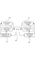
- Fig. 1 shows a schematic block diagram showing an embodiment of manufacturing equipment of an electric contact of the invention.
- Fig. 2 shows a block diagram of a control unit of the manufacturing equipment.
- Figs. 3A to 3B show a jig for supporting a metal base and a contact, wherein Fig. 3A shows a section view along an arrow line A-A of Fig. 3B, and Fig. 3B shows a plan view.
- Figs. 4A to 4B show another configuration of the jig, wherein Fig. 4A shows a side view, and Fig. 4B shows a plan view.
- Fig. 5 shows a flowchart showing a joining process in the electric contact of the invention.
- Fig. 1 shows a schematic block diagram showing an embodiment of manufacturing equipment of an electric contact of the invention.
- Fig. 2 shows a block diagram of a control unit of the manufacturing equipment.
- Figs. 3A to 3B show a jig for supporting a metal
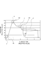
- FIG. 6 shows a diagram showing a relationship between elapsed time and pressure during joining.
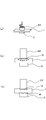
- Figs. 7A to 7C show a rough process of joining, wherein Fig. 7A shows a perspective view of a first step, Fig. 7B shows an explanatory view of a second step, and Fig. 7C shows an explanatory view of a third step.
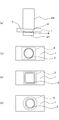
- Figs. 8A to 8B show a relationship between a rotational tool and a contact, wherein Fig. 8A shows an explanatory view in the case that the contact is larger than the rotational tool, and Fig. 8B shows an explanatory view in the case that the rotational tool is larger than the contact.
- Figs. 8A shows an explanatory view in the case that the contact is larger than the rotational tool
- Fig. 8B shows an explanatory view in the case that the rotational tool is larger than the contact.
- FIGS. 9A to 9D show a condition where a groove is formed in a back of the metal base, wherein Fig. 9A shows a front view of the condition, Fig. 9B shows an explanatory view of a first mode, Fig. 9C shows an explanatory view of a second mode, and Fig. 9D shows an explanatory view of a third mode.
- the manufacturing equipment of an electric contact is intended to obtain an electric contact by joining a metal base 1 to a contact 3.
- the metal base 1 in the embodiment extends in an approximately beltlike manner with a certain length, and is in a configuration where both side portions 1a and 1a of the metal base are folded to the outside with respect to a middle portion 1b.
- Square contacts 3 and 3 are joined to bottoms of the side portions 1a and 1a of the metal base 1 respectively.
- Fig. 1 shows a schematic block diagram of manufacturing equipment 10 of an electric contact of the embodiment (hereinafter, called 'manufacturing equipment 10').
- the manufacturing equipment 10 has a fixing plate 12 for fixing a jig 50 for superimposing and supporting the metal base 1 and the contact 3, a post 14 standing from the fixing plate 12, a tool support cylinder 18 supported in a raisable/lowerable manner by the post 14 via a raising/lowering unit 16, and a rotational tool 22 fixed to the lower side of the tool support cylinder 18 via a fixing chuck 20.
- a rotational unit 24 is disposed at an upper side of the tool support cylinder 18, and a rotational shaft of the rotational unit is connected to the rotational tool 22.
- the rotational tool 22 is configured to be raised and lowered in a forward and backward movable manner with respect to the jig 50 by the raising/lowering unit 16, and configured to rotate at a predetermined speed by the rotational unit 24.
- the rotational tool 22 has a cylindrical shape being gradually contracted in diameter toward an end thereof, and an end surface of the tool has a flat, circular shape.
- the rotational tool 22 rotates at a position corresponding to the contact 3 in a surface of the metal base 1, the surface being not contacted with the contact 3, and thereby the rotational tool is pressed into the metal base 1 while generating frictional heat between a top of the metal base 1 and the end surface of the rotational tool 22.
- a pressure measurement sensor 26 is disposed at a position in alignment with the rotational tool 22, which is connected to a control unit 35 such as an NC controller via a pressure waveform detection controller 27.
- the pressure waveform detection controller 27 converts pressure of the rotational tool 22 detected by the pressure measurement sensor 26 into a waveform showing variation in pressure after a certain time has passed as shown in Fig. 6 (showing a correlation between time and pressure).
- the pressure measurement sensor 26 and the pressure waveform detection controller 27 configure a pressure detection unit 25 of the invention.
- the control unit 35 is connected to a position calculating unit 29 disposed near the raising/lowering unit 16, and furthermore connected to a rotational speed detection unit 31 and a motor torque detection unit 33 disposed near the fixing chuck 20 respectively.
- the pressure detection unit 25 detects pressure of the rotational tool 22 to the metal base 1, the rotational tool being pressed to the metal base 1 by the raising/lowering unit 16.
- the position calculating unit 29 calculates a position of the rotational tool 22 vertically advancing and retracting by the raising/lowering unit 16, that is, calculates a distance of the tool from the metal base 1 based on a drive signal from the raising/lowering unit 16.
- the rotational speed detection unit 31 and the motor torque detection unit 33 detect rotational speed and torque of the rotational tool 22 respectively.
- control unit 35 controls the advancement and retraction of the rotational tool 22 based on a signal outputted from each of the pressure detection unit 25 and the position calculating unit 29, and controls rotation of the rotational tool 22 based on a signal outputted from each of the rotational speed detection unit 31 and the motor torque detection unit 33.
- the jig 50 for superimposing and supporting the metal base 1 and the contact 3.
- the jig 50 has a base part 51 and a holding part 55 that is removably mounted on the base part 51, and holds the metal base 1 to the jig 50.
- the base part 51 has recesses 53 to be fitted with the contacts 3 respectively, and has a top shaped in accordance with the metal base 1.
- the holding part 55 has a pair of side holders 55a, 55a that contact to end faces of both side portions 1a and 1a of the metal base 1 respectively, and a pair of middle holders 55b, 55b that contact to both sides of middle portion 1b of the metal base 1 respectively.
- each of the contacts 3 is fitted into each of the recesses 53 of the base part 51, and the metal base 1 is superimposed thereon, and then the holding part 55 is mounted on the base part 51.
- the side holders 55a and the middle holders 55b contact to the side portions 1a, 1a of the metal base 1 and the middle portion 1b thereof respectively.
- the metal base 1 is held to be prevented from rising from the base part 51, so that the metal base 1 and the contact 3 are supported in a superimposed manner while being tightly contacted with each other.
- the jig 50 is disposed on the pressure measurement sensor 26 of the manufacturing equipment 10, and fixed to the fixing plate 12 by a not-shown fixing unit, and as shown an imaginary line in Fig. 3A, the end face having the flat surface of the rotational tool 22 is pressed into the metal base 1 at a position corresponding to the contact 3 in the surface, which is not contacted with the contact 3, of the metal base 1 (a top of the metal base 1).
- the jig 50 for example, ceramics or stainless steel is preferably used. Since such material has high heat resistance and low heat conductivity, frictional heat caused by rotation of the end face of the rotational tool 22 on the metal base 1 is hardly transferred to the jig 50. As a result, the frictional heat can be efficiently transferred to the contact surfaces of the metal base 1 and the contact 3, and consequently joining between the metal base 1 and the contact 3, described later, can be quickly performed.
- the metal base 1 has a configuration where one side portion 1c to be joined with the contact 3 is connected with the other side portion 1d being wide via a curved middle portion 1b.
- One side portion of the base part 51 is shaped to be raised in accordance with the metal base 1, and the other side portion 1d being wide of the metal base 1 is set thereon, and fixed by fastening to the base part 51 by a bolt B.
- Fig. 6 shows a relationship between elapsed time (horizontal axis) and pressure (vertical axis) when the rotational tool 22 is pressed into the surface, being not contacted with the contact 3, of the metal base 1 while being rotated.
- the rotational tool 22 is advanced to the metal base 1 while being rotated, and when the rotational tool 22 contacts to the metal base 1 as shown in Fig. 7A, pressure begins to increase.
- a slight gap may be formed between the metal base 1 and the contact 3, for example, in the case that the metal base 1 is slightly bent due to fluctuation in finished size or the like. In this case, pressure is hardly applied from the rotational tool 22, and gradually increases as shown by a sign a in Fig. 6.
- true pressing depth of the rotational tool 22 is not clearly known.
- the position at which pressure abruptly increases is defined as the adhesion start point P1 as described above, and thereby the true pressing depth of the rotational tool 22 can be confirmed.
- the rotational tool 22 is pressed into the metal base 1 while being rotated at a predetermined speed, thereby frictional heat generated between the rotational tool 22 and the metal base 1 is transferred even to the contact surfaces of the metal base 1 and the contact 3 as shown by arrows in Fig. 7B.
- high temperature heat and pressure are applied to the contact surfaces of the metal base 1 and the contact 3
- solid state diffusion welding is performed between the joining surfaces of the metal base 1 and the contact 3 as shown in Fig. 7C, so that a solid state diffusion welding region R is formed, and the metal base 1 and the contact 3 are joined to each other via the solid state diffusion welding region R.
- the solid state diffusion welding is a type of diffusion welding, which uses diffusion of atoms for bonding, and refers to a joining method in a solid phase without melting joining surfaces.
- the pressure detection unit 25 detects a waveform showing change in pressure of the rotational tool 22 with elapsed time when the rotational tool 22 is pressed into the metal base 1 at a predetermined speed (refer to Fig. 6), and the control unit 35 controls the advancement and retraction of the rotational tool 22 based on the signal from the pressure detection unit 25, so that the metal base 1 and the contact 3 can be joined by solid state diffusion welding.
- the control unit of the manufacturing equipment 10 is designed such that when the rotational tool 22 is pressed into the metal base at a predetermined speed while being rotated, the control unit determines a position at which pressure detected by the pressure detection unit 25 exceeds a predetermined value as the adhesion start point P1, and drives the rotational tool 22 based on positional information from the position calculating unit 29 such that the rotational tool 22 is pressed from the adhesion start point P1 to the predetermined depth position, then the tool is held at the depth position for a certain time, and then raised (refer to Fig. 2).
- control unit 35 has a not-shown storage device, which is beforehand inputted with conditions such as a pressure to be a reference for detecting the adhesion start point P1, a depth by which the rotational tool 22 is pressed from the adhesion start point P1, and a period for which the rotational tool 22 is held at a position of the depth, and stores the conditions.
- control operation of the control unit 35 is described with reference to a flowchart shown in Fig. 5.
- control operation of the control unit 35 is not limited to operation shown by the flowchart.
- the control unit 35 begins to compare the increased pressure with the predetermined pressure beforehand stored in the control unit 35 in step S1, and when pressure of the rotational tool 22 exceeds the predetermined value, the control unit determines a position of the rotational tool 22 at that time as the adhesion start point P1.
- step S2 when a pressing depth of the rotational tool 22 is determined to be large compared with the predetermined depth stored in the control unit 35 based on the positional information on the rotational tool 22, operation is advanced to step S3, and lowering of the rotational tool 22 is stopped.
- step S4 when pressure of the rotational tool 22 is determined to be constant in step S4, operation is advanced to step 5.
- step S5 when time elapsed from a point when pressure is determined to be flattened exceeds a certain time beforehand stored in the control unit 35, the rotational tool 22 rises and returns to an initial position in step S6.
- the rotational tool 22 is pressed into the metal base 1, which is supported being superimposed on the contact 3, at a predetermined speed while being rotated.
- joining between the metal base 1 and the contact 3 according to the invention does not use so-called friction stir welding where plastic flow S is formed to range over both members to be joined so as to join the members via the plastic flow S, and uses solid state diffusion welding to join the metal base 1 and the contact 3 to each other.
- time required for joining between the metal base 1 and the contact 3 can be reduced, leading to improvement in productivity.
- pressing depth of the rotational tool 22 can be decreased to the minimum necessary depth, dimension stability can be improved, and a dent, an impression, contact marks, discoloration and the like can be suppressed to appear on the contact 3.
- pressing depth of the rotational tool 22 is controlled, thereby an electric contact having substantially no fluctuation in quality can be stably produced.
- step S1 pressure of the rotational tool 22 is compared to a predetermined value being beforehand set, and thereby whether the pressure exceeds the predetermined value is determined in order to detect the adhesion start point P1.
- a predetermined value a value selected from 5 to 20 kg is preferably used.
- the control unit 35 using NC control or the like controls the rotational tool 22 so as to be pressed from the point to a certain pressing depth position, and thereby the certain pressing depth can be constantly kept without any fluctuation.
- the pressing depth of the rotational tool 22 from the adhesion start point P1 is preferably 1/20 or more of thickness of the metal base 1, and more preferably 1/20 to 1/5 thereof.
- the pressing depth is most preferably about 0.2 mm.
- the pressing depth is set in this way, and thereby the metal base 1 and the contact 3 can be securely joined by solid state diffusion welding with adequate joining strength.
- an uneven pressing (uneven contact) condition may slightly occur between the metal base 1 and the contact 3, resulting in inadequate joining strength.
- impression and the like may conspicuously appear, which is not preferable in the light of quality and accuracy of products, and causes reduction in workability.
- the rotational tool 22 when the rotational tool 22 is pressed into the metal base 1, the rotational tool 22 is pressed to a lowering position after pressure of the tool reaches the peak P2.
- such pressing depth is not limitative in the invention, and when the solid state diffusion welding is performed between the contact surfaces of the metal base 1 and the contact 3 at a depth position before pressure of the tool reaches the peak P2, the tool may be pressed to the depth position.
- the pressing depth of the rotational tool 22 is set to be at least the depth at which the pressure reaches the peak P2 as shown in Fig. 6, and thereby thermal energy required for solid state diffusion welding between the joining surfaces of the metal base 1 and the contact 3 can be adequately generated.
- the rotational tool 22 that has been pressed to a predetermined depth position is stopped at the position and held for a certain time.
- such holding time is not always needed, and the rotational tool 22 may be immediately raised after it has been pressed to the predetermined depth position.
- the rotational tool 22 is held for a certain time, and thereby thermal energy required for solid state diffusion welding between the joining surfaces of the metal base 1 and the contact 3 can be securely transferred, and consequently weldability between the metal base 1 and the contact 3 can be stabilized.
- the rotational tool 22 can be controlled such that pressure of the rotational tool 22 in a condition shown by the sign c in Fig. 6 is set to be, for example, 65 kg, and if a certain pressure is kept for a period of, for example, 0.5 sec or more after the pressure has been decreased to less than 65 kg, the pressure is considered to be constant, and the rotational tool 22 is held for a certain time from the end of the period.
- Materials of the metal base 1 and the contact 3 used in the manufacturing method are not particularly limited. However, a metal material is preferably used, which is feasible for solid state diffusion welding between contact surfaces of both. For example, Cu or Cu-based alloy is preferably used for the metal base 1.
- At least a contact surface, to be contacted with the contact 3, of the metal base 1 may be subjected to plating including metal being feasible for mutual solid state diffusion with the contact 3.
- plating for example, Sn plating, Ag plating, Au plating, Pb-free plating (Sn-Ag-based material and the like), and Zn plating are given.
- Sn plating, Ag plating, Au plating, Pb-free plating (Sn-Ag-based material and the like), and Zn plating are given.
- Such plating is applied, thereby when the metal base 1 is heated by frictional heat caused by the rotational tool 22, a plating layer on the metal base 1 exhibits solid state diffusion so that the metal base 1 can be more easily joined with the contact 3. That is, pressing depth of the rotational tool 22 can be reduced, and holding time after pressing the rotational tool 22 can be reduced, consequently productivity can be improved.
- the pressing depth can be at least about 0.07 mm, and even if such a degree of pressing depth is given, she
- Cd-free Ag alloy or Cd alloy as shown in the following Table 1 can be used as a material of the contact 3.
- the contact 3 including such a material can be directly joined to the metal base 1 by using the manufacturing method of the invention.
- an oxide contact is preferably used, which is beforehand cladded with a metal layer to be easily joined, or beforehand subjected to plating having an appropriate thickness.
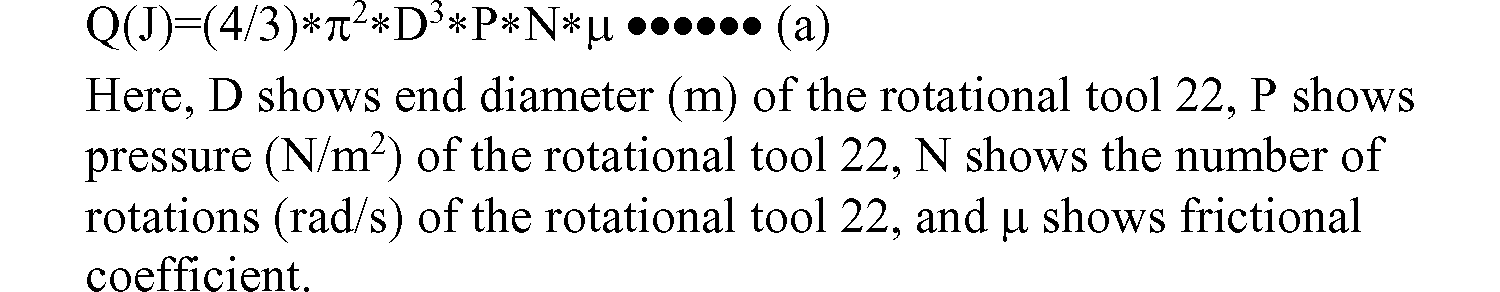
- diameter D of the rotational tool 22 (refer to Figs. 8A to 8B) is 3 to 9 mm, the number of rotations of the rotational tool 22 is 3000 to 10000 rpm, and thickness of the metal base 1 is 1 to 2.5 mm. According to this, since frictional heat caused by the rotational tool 22 is effectively transferred to the contact surfaces of the metal base 1 and the contact 3, solid state diffusion welding can be easily performed.
- the energy Q is greatly influenced by the cube of the tool diameter D of the rotational tool 22. Therefore, as the end diameter D of the rotational tool 22 is larger, the energy Q is larger, and consequently the contact 3 is more easily joined to the metal base 1. Conversely, as the end diameter D of the rotational tool 22 is smaller, since the energy Q is abruptly reduced, the contact 3 is harder to be joined to the metal base 1.
- the diameter D of the rotational tool 22 is 3 to 9 mm, that is, considerably small compared with tool diameter of about 16 mm used for typical friction stir welding, and therefore the energy Q is also small.
- the metal base 1 is joined to the contact 3 by solid state diffusion welding rather than by joining using plastic flow S as described before. Therefore, high energy Q for forming plastic flow S deep enough to reach each joining surface is not necessary, and therefore the above conditions are used, so that the metal base 1 can be adequately joined to the contact 3.
- Fig. 8 shows a specific example of an end face shape of the rotational tool 22 and a shape of the contact 3. That is, in an example shown in Fig. 8A, the diameter D of the rotational tool 22 is sized to be inscribed in the contact 3. Therefore, frictional heat caused by the rotational tool 22 is efficiently transferred to the contact 3. In an example shown in Fig. 8B, the diameter D of the rotational tool 22 is sized to be circumscribed with the contact 3. In this case, since the whole joining surface of the contact 3 is covered by the end face of the rotational tool 22, frictional heat caused by the rotational tool 22 can be securely transferred to the whole joining surface of the contact 3.
- a groove having a predetermined depth is preferably provided on a surface, which is to be contacted with the contact 3, of the metal base 1.
- a groove 2 having a predetermined depth is formed on a surface at a contact 3 side of the metal base 1.
- the groove 2 may be in a shape of a circle as shown in Fig. 9B, a square as shown in Fig. 9C, a straight line, two straight lines, or intersected lines like a cross, that is, may be in any shape if the groove can provide the anchor effect.
- the groove 2 may be formed by a dent caused by pressing, or may be formed by scribing using a pointed scribing pin or the like. Depth of the groove 2 may be extremely shallow, for example, 0.1 mm or less.
- Fig. 9D shows a case that the contact 3 is in a circular shape.
- the groove 2 is also in a circular shape.
- the joining surface of the contact 3 can be efficiently covered by the end of the rotational tool 22 compared with a contact 3 having a square shape.
- the diameter D of the rotational tool 22 can be easily set, and when joining is performed, the center of the rotational tool 22 can be easily aligned with the center of the contact 3, and therefore positioning is facilitated, and furthermore uniformity in a joint is easily secured.
Landscapes
- Engineering & Computer Science (AREA)
- Mechanical Engineering (AREA)
- Manufacturing & Machinery (AREA)
- Pressure Welding/Diffusion-Bonding (AREA)
- Manufacture Of Switches (AREA)
Abstract
Description
Kinya AOTA 'Spot Friction Stir Welding of Al/Cu' (Whole Country Meeting of Japan Welding Society Lecture Abstract, September 2004), relating to a joining between an aluminum plate and a copper plate, mentions on the interfacial characteristics of the joining when a joining tool is pressed on top of a portion where the aluminum plate and the copper plate are overlapped. It, however, doesn't mention on the controlling of the depth of the pressing.
JP-A-S60-250891 discloses a manufacturing method of an electric contact, which includes: forming a series of grooves having a certain pitch on a surface of a metal base; laying a piece of contact on the series of grooves; grasping while adding pressure the metal base and the piece of contact between a horn and an anvil with which an ultrasonic welding machine is equipped; and ultrasonic stirring a horn head in a direction aliened along the grooves, such that the piece of contact and the metal base can join each other.
JP-A-S55-006746 discloses a manufacturing method of an electric contact, which includes: grasping while adding pressure a metal base and a contact between two electrodes; heating by allowing to pass electric current between the electrodes; and quick-chilling after the heating, such that the metal base and the contact can join each other.
JP-A-H10-269883 discloses a manufacturing method of a contact member, which includes: forming in a metal base a crevice smaller than an outer diameter of a contact, the contact being made of a meltable material; laying the contact on the crevice, and welding and press-molding the contact laid on the crevice by use of a welding machine, such that the contact can be made to weld to the metal base in a predetermined shape.
JP-A-S58-186115 discloses a manufacturing method of a silver/oxide type electric contact, which includes: inserting two of contact members between resistive electrodes by use of a resistance welding machine; pouring at least enough amount of an organic solvent to replace air in said inserted contact members; and adding pressure and allowing to pass electric current to thereby make a complex contact constituted by the two of contact members.
JP-A-S61-017394 discloses a manufacturing method of a contact material, which includes: overlaying a first layer, the first layer consisting of a first component to constitute the contact material, to weld with a second layer, the second layer consisting of at least a second component, and being arranged to be in a thickness so as to become a predetermined composition of alloy when melting.
Katsuyuki Yoshikawa 'Micro Spot Friction Welding', 11th Symposium MATE 2005, Japan Welding Society, 2005, pp.421-424 Kinya AOTA 'Spot Friction Stir Welding of Al/Cu' (Whole Country Meeting of Japan Welding Society Lecture Abstract, September 2004)
a jig for superimposing and supporting a contact and a metal base,
a rotational tool that rotates at a predetermined speed, and advances/retracts to/from the jig so as to be pressed into the metal base at a position corresponding to the contact on a surface of the metal base, the surface being not contacted with the contact,
a detection unit of pressure of the rotational tool, or a detection unit of motor torque of the rotational tool, and
a control unit that controls raising and lowering of the rotational tool based on a signal from the pressure detection unit or the motor torque detection unit.
Fig. 2 shows a block diagram of a control unit of the manufacturing equipment.
Figs. 3A to 3B show a jig for supporting a metal base and a contact, wherein Fig. 3A shows a section view along an arrow line A-A of Fig. 3B, and Fig. 3B shows a plan view.
Figs. 4A to 4B show another configuration of the jig, wherein Fig. 4A shows a side view, and Fig. 4B shows a plan view.
Fig. 5 shows a flowchart showing a joining process in the electric contact of the invention.
Fig. 6 shows a diagram showing a relationship between elapsed time and pressure during joining.
Figs. 7A to 7C show a rough process of joining, wherein Fig. 7A shows a perspective view of a first step, Fig. 7B shows an explanatory view of a second step, and Fig. 7C shows an explanatory view of a third step.
Figs. 8A to 8B show a relationship between a rotational tool and a contact, wherein Fig. 8A shows an explanatory view in the case that the contact is larger than the rotational tool, and Fig. 8B shows an explanatory view in the case that the rotational tool is larger than the contact.
Figs. 9A to 9D show a condition where a groove is formed in a back of the metal base, wherein Fig. 9A shows a front view of the condition, Fig. 9B shows an explanatory view of a first mode, Fig. 9C shows an explanatory view of a second mode, and Fig. 9D shows an explanatory view of a third mode.

Claims (10)
- A manufacturing method of an electric contact,
wherein:
a contact and a metal base are superimposed and supported by a jig, and
a rotational tool is pressed into the metal base while being rotated, the rotational tool rotating at a predetermined speed, and advancing/retracting to/from the jig, at a position corresponding to the contact on a surface of the metal base, the surface being not contacted with the contact, so that the contact and the metal base are joined by solid state diffusion welding by using frictional heat generated by friction between the rotational tool and the metal base, and then
the rotational tool is retracted from the metal base. - The manufacturing method of an electric contact according to claim 1,
wherein
pressure of the rotational tool or motor torque for rotating the rotational tool is detected, and a pressing position at which the pressure or the motor torque exceeds a predetermined value is assumed as an adhesion start point, then the rotational tool is further pressed from the adhesion start point to a predetermined depth position. - The manufacturing method of an electric contact according to claim 2,
wherein
the rotational tool is further pressed from the adhesion start point to the predetermined depth position, and the rotational tool is held at the position for a certain time, and then retracted from the metal base. - The manufacturing method of an electric contact according to claim 2 or 3,
wherein
pressing depth of the rotational tool from the adhesion start point is 1/20 or more of thickness of the metal base. - The manufacturing method of an electric contact according to any one of claims 1 to 4,
wherein
a groove having a predetermined depth is provided on a surface of the metal base, the surface to be contacted with the contact. - The manufacturing method of an electric contact according to any one of claims 1 to 5,
wherein
at least a contact surface of the metal base, the contact surface to be contacted with the contact, is subjected to plating including metal being feasible for mutual solid state diffusion with the contact. - The manufacturing method of an electric contact according to any one of claims 1 to 6,
wherein
diameter of the rotational tool is 3 to 9 mm, the number of rotations of the rotational tool is 3000 to 10000 rpm, and thickness of the metal base is 1 to 2.5 mm. - Manufacturing equipment of an electric contact,
comprising:
a jig for superimposing and supporting a contact and a metal base,
a rotational tool that rotates at a predetermined speed, and advances/retracts to/from the jig so as to be pressed into the metal base at a position corresponding to the contact on a surface of the metal base, the surface being not contacted with the contact,
a detection unit of pressure of the rotational tool, or a detection unit of motor torque of the rotational tool, and
a control unit that controls raising/lowering of the rotational tool based on a signal from the pressure detection unit or the motor torque detection unit,
wherein
when the rotational tool is pressed into the metal base while being rotated, the control unit determines a position, at which the pressure or the motor torque detected by the pressure detection unit or the motor torque detection unit exceeds a predetermined value, as an adhesion start point, and drives the rotational tool so as to be further pressed to a predetermined depth position from the adhesion start point, and then retracted from the metal base. - The manufacturing equipment of an electric contact according to claim 8,
wherein:
the control unit drives the rotational tool so as to be further pressed from the adhesion start point to a predetermined depth position, and held at the position for a certain time, and then retracted from the metal base. - The manufacturing equipment of an electric contact according to claim 9,
wherein:
the jig is formed of ceramics or stainless steel.
Priority Applications (4)
| Application Number | Priority Date | Filing Date | Title |
|---|---|---|---|
| CN200980104558.1A CN101939128B (en) | 2008-02-08 | 2009-01-16 | Manufacturing method of electric contact and manufacturing equipment of electric contact |
| JP2010540289A JP5287866B2 (en) | 2008-02-08 | 2009-01-16 | Electric contact manufacturing method and electric contact manufacturing apparatus |
| EP09707429.8A EP2242605A4 (en) | 2008-02-08 | 2009-01-16 | ELECTRIC CONTACT MANUFACTURING METHOD AND ELECTRIC CONTACT MANUFACTURING EQUIPMENT |
| US12/866,727 US8196300B2 (en) | 2008-02-08 | 2009-01-16 | Manufacturing method of electric contact and manufacturing equipment of electric contact |
Applications Claiming Priority (2)
| Application Number | Priority Date | Filing Date | Title |
|---|---|---|---|
| JP2008028597 | 2008-02-08 | ||
| JP2008-028597 | 2008-02-08 |
Publications (1)
| Publication Number | Publication Date |
|---|---|
| WO2009098836A1 true WO2009098836A1 (en) | 2009-08-13 |
Family
ID=40951917
Family Applications (1)
| Application Number | Title | Priority Date | Filing Date |
|---|---|---|---|
| PCT/JP2009/000142 Ceased WO2009098836A1 (en) | 2008-02-08 | 2009-01-16 | Manufacturing method of electric contact and manufacturing equipment of electric contact |
Country Status (5)
| Country | Link |
|---|---|
| US (1) | US8196300B2 (en) |
| EP (1) | EP2242605A4 (en) |
| JP (1) | JP5287866B2 (en) |
| CN (1) | CN101939128B (en) |
| WO (1) | WO2009098836A1 (en) |
Cited By (4)
| Publication number | Priority date | Publication date | Assignee | Title |
|---|---|---|---|---|
| CN102500911A (en) * | 2011-11-21 | 2012-06-20 | 哈尔滨工业大学 | Pre-friction aid device and method for implementing diffusion bonding by using same |
| CN104259651A (en) * | 2014-08-13 | 2015-01-07 | 山西环界石油钻具制造股份有限公司 | Friction-welding method for non-magnetic metal material and special-shaped metal material |
| CN110026758A (en) * | 2019-05-21 | 2019-07-19 | 温州德盛自动化科技有限公司 | Relay base capping detection integrated production line |
| DE102018103974A1 (en) * | 2018-02-22 | 2019-08-22 | Bayerische Motoren Werke Aktiengesellschaft | Friction welding device with reusable pressure piece |
Families Citing this family (18)
| Publication number | Priority date | Publication date | Assignee | Title |
|---|---|---|---|---|
| CN103108720A (en) * | 2010-08-02 | 2013-05-15 | 梅加斯特尔技术公司 | System for using high rotary speed for minimizing the load during friction stir welding |
| JP6040352B2 (en) * | 2011-03-29 | 2016-12-07 | 学校法人近畿大学 | Friction stir processing apparatus and friction stir processing method |
| JP5893533B2 (en) * | 2012-09-04 | 2016-03-23 | 株式会社エフテック | Friction stir welding equipment |
| CN103035420B (en) * | 2012-11-27 | 2016-04-13 | 上海达达电气有限公司 | A kind of silver contact point structure of contact system and manufacture method |
| CN104871273B (en) * | 2012-12-14 | 2017-12-19 | 田中贵金属工业株式会社 | Rivet type contact and its manufacture method |
| CN103354210B (en) * | 2013-06-27 | 2016-08-10 | 清华大学 | A kind of bonding method and use the bonding structure that this bonding method formed |
| DE102014101627A1 (en) * | 2014-02-10 | 2015-08-13 | Ms Spaichingen Gmbh | Rack for a machine |
| DE102014005315B3 (en) | 2014-04-10 | 2015-06-11 | Grenzebach Maschinenbau Gmbh | Method and device for detecting the mechanical forces at the welding pin tip in the process of friction stir welding and computer program and machine readable carrier with a program code for carrying out the method |
| CN106133865B (en) * | 2014-04-17 | 2018-01-09 | 西门子公司 | The processing facility that switch element for electromagnetic switchgear is processed |
| JP6212028B2 (en) * | 2014-12-26 | 2017-10-11 | トヨタ自動車株式会社 | Point friction stir welding structure |
| JP6554029B2 (en) * | 2015-11-24 | 2019-07-31 | 川崎重工業株式会社 | Friction stir spot welding device and friction stir spot welding method |
| CN108885953B (en) * | 2016-04-01 | 2019-10-25 | 打矢恒温器株式会社 | How to make electrical contacts |
| JP6978294B2 (en) * | 2017-11-30 | 2021-12-08 | 矢崎総業株式会社 | Terminal connection method and terminal |
| JP6952872B2 (en) * | 2018-03-20 | 2021-10-27 | 三菱電機株式会社 | Contactor and manufacturing method of contactor |
| FR3121855B1 (en) * | 2021-04-16 | 2024-04-19 | Stirweld | Friction stir welding head and method using same |
| CN114823194B (en) * | 2022-06-07 | 2025-07-01 | 温州赛金电工合金有限公司 | A three-composite contact processing technology |
| CN114939714B (en) * | 2022-06-08 | 2023-05-16 | 南昌航空大学 | An electromagnetic pulse assisted friction stir lock welding processing device and method |
| CN119140974B (en) * | 2024-11-18 | 2025-03-14 | 温州聚星科技股份有限公司 | A cold welding device for multi-layer composite silver contacts |
Citations (9)
| Publication number | Priority date | Publication date | Assignee | Title |
|---|---|---|---|---|
| JPS57101310A (en) * | 1980-10-23 | 1982-06-23 | Bbc Brown Boveri & Cie | Welding machine for welding contact piece to contact piece base |
| JPH0647570A (en) * | 1992-07-13 | 1994-02-22 | Mitsubishi Heavy Ind Ltd | Friction welding method for different material |
| JP2001090655A (en) * | 1999-09-22 | 2001-04-03 | Toyota Autom Loom Works Ltd | Swash plate type swash plate compressor and method of manufacturing the same |
| JP2002059274A (en) * | 2000-08-09 | 2002-02-26 | Showa Corp | Friction welding method |
| JP2003311440A (en) * | 2002-04-19 | 2003-11-05 | Univ Nihon | Metal plate joined by friction welding and method of joining metal plate by friction welding |
| JP2005103615A (en) * | 2003-09-30 | 2005-04-21 | Nippon Chemicon Corp | Fixing jig for friction stir welding and method for manufacturing laminated electronic component using the jig |
| WO2005092558A1 (en) * | 2004-03-25 | 2005-10-06 | Nihon University | Method and device for joining metal plates by friction welding |
| JP2006102748A (en) * | 2004-09-30 | 2006-04-20 | Mazda Motor Corp | Friction welding equipment |
| JP2007319931A (en) * | 2006-05-02 | 2007-12-13 | Osaka Industrial Promotion Organization | Friction stir processing method and backing jig for friction stir processing |
Family Cites Families (18)
| Publication number | Priority date | Publication date | Assignee | Title |
|---|---|---|---|---|
| US4139140A (en) * | 1976-09-21 | 1979-02-13 | G. Rau | Method for producing an electrical contact element |
| JPS556746A (en) | 1978-06-30 | 1980-01-18 | Fuji Electric Co Ltd | Method of manufacturing electric contactor |
| GB2102200B (en) * | 1981-07-17 | 1985-05-30 | Philips Electronic Associated | Infra-red radiation detector |
| JPS58186115A (en) | 1982-04-23 | 1983-10-31 | 三菱マロリ−冶金工業株式会社 | Method of producing silver-oxide series electric contact |
| JPS60250891A (en) | 1984-05-25 | 1985-12-11 | Fuji Electric Co Ltd | Manufacture of electric contact |
| US4625401A (en) * | 1984-06-25 | 1986-12-02 | Amp Incorporated | Method of gold coating an article |
| JPS6117394A (en) | 1984-07-04 | 1986-01-25 | Fujitsu Ltd | Production of joined material |
| EP0333600B1 (en) * | 1988-02-25 | 1993-05-12 | Merlin Gerin | Process for producing a composite work piece, for instance for electric contacts |
| JPH10269883A (en) | 1997-03-27 | 1998-10-09 | Mitsubishi Electric Corp | Method of manufacturing contact member and contact member |
| JP4050478B2 (en) * | 2001-03-29 | 2008-02-20 | マツダ株式会社 | Processing control method using friction stirring, computer program for executing the method, and storage medium storing the computer program |
| JP3471338B2 (en) * | 2001-07-30 | 2003-12-02 | 川崎重工業株式会社 | Friction stir welding equipment |
| JP3538406B2 (en) * | 2001-10-17 | 2004-06-14 | 川崎重工業株式会社 | Friction stir welding equipment |
| US6742697B2 (en) * | 2002-04-29 | 2004-06-01 | The Boeing Company | Joining of structural members by friction plug welding |
| JP4537132B2 (en) | 2004-07-07 | 2010-09-01 | 川崎重工業株式会社 | Friction stir welding method for spot welding |
| US7641096B2 (en) * | 2005-01-24 | 2010-01-05 | The Boeing Company | Friction stir welding apparatus |
| JP4786191B2 (en) * | 2005-02-02 | 2011-10-05 | 川崎重工業株式会社 | Joining tool for friction stir welding equipment |
| CN101218697B (en) * | 2005-07-05 | 2010-12-08 | 松下电器产业株式会社 | Connecting device between batteries |
| JP5055814B2 (en) * | 2006-04-13 | 2012-10-24 | マツダ株式会社 | Joining method and joining apparatus |
-
2009
- 2009-01-16 US US12/866,727 patent/US8196300B2/en not_active Expired - Fee Related
- 2009-01-16 CN CN200980104558.1A patent/CN101939128B/en not_active Expired - Fee Related
- 2009-01-16 WO PCT/JP2009/000142 patent/WO2009098836A1/en not_active Ceased
- 2009-01-16 EP EP09707429.8A patent/EP2242605A4/en not_active Withdrawn
- 2009-01-16 JP JP2010540289A patent/JP5287866B2/en active Active
Patent Citations (9)
| Publication number | Priority date | Publication date | Assignee | Title |
|---|---|---|---|---|
| JPS57101310A (en) * | 1980-10-23 | 1982-06-23 | Bbc Brown Boveri & Cie | Welding machine for welding contact piece to contact piece base |
| JPH0647570A (en) * | 1992-07-13 | 1994-02-22 | Mitsubishi Heavy Ind Ltd | Friction welding method for different material |
| JP2001090655A (en) * | 1999-09-22 | 2001-04-03 | Toyota Autom Loom Works Ltd | Swash plate type swash plate compressor and method of manufacturing the same |
| JP2002059274A (en) * | 2000-08-09 | 2002-02-26 | Showa Corp | Friction welding method |
| JP2003311440A (en) * | 2002-04-19 | 2003-11-05 | Univ Nihon | Metal plate joined by friction welding and method of joining metal plate by friction welding |
| JP2005103615A (en) * | 2003-09-30 | 2005-04-21 | Nippon Chemicon Corp | Fixing jig for friction stir welding and method for manufacturing laminated electronic component using the jig |
| WO2005092558A1 (en) * | 2004-03-25 | 2005-10-06 | Nihon University | Method and device for joining metal plates by friction welding |
| JP2006102748A (en) * | 2004-09-30 | 2006-04-20 | Mazda Motor Corp | Friction welding equipment |
| JP2007319931A (en) * | 2006-05-02 | 2007-12-13 | Osaka Industrial Promotion Organization | Friction stir processing method and backing jig for friction stir processing |
Non-Patent Citations (1)
| Title |
|---|
| See also references of EP2242605A4 * |
Cited By (5)
| Publication number | Priority date | Publication date | Assignee | Title |
|---|---|---|---|---|
| CN102500911A (en) * | 2011-11-21 | 2012-06-20 | 哈尔滨工业大学 | Pre-friction aid device and method for implementing diffusion bonding by using same |
| CN102500911B (en) * | 2011-11-21 | 2014-02-12 | 哈尔滨工业大学 | Pre-friction aid device and method for implementing diffusion bonding by using same |
| CN104259651A (en) * | 2014-08-13 | 2015-01-07 | 山西环界石油钻具制造股份有限公司 | Friction-welding method for non-magnetic metal material and special-shaped metal material |
| DE102018103974A1 (en) * | 2018-02-22 | 2019-08-22 | Bayerische Motoren Werke Aktiengesellschaft | Friction welding device with reusable pressure piece |
| CN110026758A (en) * | 2019-05-21 | 2019-07-19 | 温州德盛自动化科技有限公司 | Relay base capping detection integrated production line |
Also Published As
| Publication number | Publication date |
|---|---|
| EP2242605A4 (en) | 2014-02-26 |
| US8196300B2 (en) | 2012-06-12 |
| CN101939128B (en) | 2014-03-12 |
| JP5287866B2 (en) | 2013-09-11 |
| JP2011508945A (en) | 2011-03-17 |
| EP2242605A1 (en) | 2010-10-27 |
| CN101939128A (en) | 2011-01-05 |
| US20110099808A1 (en) | 2011-05-05 |
Similar Documents
| Publication | Publication Date | Title |
|---|---|---|
| US8196300B2 (en) | Manufacturing method of electric contact and manufacturing equipment of electric contact | |
| EP1046453B1 (en) | Friction stir welding apparatus | |
| US8164021B1 (en) | Electrically assisted friction stir welding | |
| US20110233173A1 (en) | Seam welding method and machine therefor | |
| JP5431790B2 (en) | Friction stir spot welding apparatus and friction stir spot welding method | |
| KR20110007595A (en) | Vibration Spot Welding Machine and Vibration Spot Welding Method | |
| JP4479416B2 (en) | Friction spot welding method and apparatus | |
| JPWO2015033537A1 (en) | Indirect spot welding equipment | |
| JP4550086B2 (en) | Projection welding method for highly conductive workpieces | |
| JP2023013804A (en) | Joining apparatus and joining method for friction stir welding and resistance welding | |
| JP7842529B2 (en) | Spot welding method | |
| JP4940334B2 (en) | Projection welding method for highly conductive workpieces | |
| CN118002903B (en) | Welding equipment and high-frequency welding method for steel pipes with unequal wall thicknesses | |
| JP4946991B2 (en) | Manufacturing method of electrical contact | |
| JP2000225470A (en) | Welding head of resistance welding equipment | |
| EP3986656A1 (en) | System and method for forming a weld along a length | |
| CN114226946B (en) | Ultrasonic welding device and welding method | |
| JP4905410B2 (en) | Manufacturing method of electrical contact | |
| CN215545772U (en) | Cylinder workpiece fixing tool and friction stir welding equipment | |
| JP4994982B2 (en) | Diffusion bonding method for copper thin-walled pipe | |
| JP4973592B2 (en) | Manufacturing method of electrical contact | |
| CN102371411A (en) | Automatic welding equipment and welding method thereof | |
| JP5120052B2 (en) | Manufacturing method of electrical contact | |
| CN216177535U (en) | Ultrasonic welding instrument board for automobile | |
| CN213437759U (en) | Spot welding device for assembling nut and sheet metal part |
Legal Events
| Date | Code | Title | Description |
|---|---|---|---|
| WWE | Wipo information: entry into national phase |
Ref document number: 200980104558.1 Country of ref document: CN |
|
| 121 | Ep: the epo has been informed by wipo that ep was designated in this application |
Ref document number: 09707429 Country of ref document: EP Kind code of ref document: A1 |
|
| REEP | Request for entry into the european phase |
Ref document number: 2009707429 Country of ref document: EP |
|
| WWE | Wipo information: entry into national phase |
Ref document number: 2009707429 Country of ref document: EP |
|
| WWE | Wipo information: entry into national phase |
Ref document number: 2010540289 Country of ref document: JP |
|
| NENP | Non-entry into the national phase |
Ref country code: DE |
|
| WWE | Wipo information: entry into national phase |
Ref document number: 12866727 Country of ref document: US |