WO2009099223A1 - 容器およびそれを用いた分析容器 - Google Patents
容器およびそれを用いた分析容器 Download PDFInfo
- Publication number
- WO2009099223A1 WO2009099223A1 PCT/JP2009/052119 JP2009052119W WO2009099223A1 WO 2009099223 A1 WO2009099223 A1 WO 2009099223A1 JP 2009052119 W JP2009052119 W JP 2009052119W WO 2009099223 A1 WO2009099223 A1 WO 2009099223A1
- Authority
- WO
- WIPO (PCT)
- Prior art keywords
- container
- lid
- housing portion
- lid body
- opening
- Prior art date
- Legal status (The legal status is an assumption and is not a legal conclusion. Google has not performed a legal analysis and makes no representation as to the accuracy of the status listed.)
- Ceased
Links
Images






Classifications
-
- B—PERFORMING OPERATIONS; TRANSPORTING
- B01—PHYSICAL OR CHEMICAL PROCESSES OR APPARATUS IN GENERAL
- B01L—CHEMICAL OR PHYSICAL LABORATORY APPARATUS FOR GENERAL USE
- B01L3/00—Containers or dishes for laboratory use, e.g. laboratory glassware; Droppers
- B01L3/50—Containers for the purpose of retaining a material to be analysed, e.g. test tubes
- B01L3/508—Rigid containers without fluid transport within
- B01L3/5082—Test tubes per se
- B01L3/50825—Closing or opening means, corks, bungs
-
- A—HUMAN NECESSITIES
- A61—MEDICAL OR VETERINARY SCIENCE; HYGIENE
- A61J—CONTAINERS SPECIALLY ADAPTED FOR MEDICAL OR PHARMACEUTICAL PURPOSES; DEVICES OR METHODS SPECIALLY ADAPTED FOR BRINGING PHARMACEUTICAL PRODUCTS INTO PARTICULAR PHYSICAL OR ADMINISTERING FORMS; DEVICES FOR ADMINISTERING FOOD OR MEDICINES ORALLY; BABY COMFORTERS; DEVICES FOR RECEIVING SPITTLE
- A61J1/00—Containers specially adapted for medical or pharmaceutical purposes
-
- F—MECHANICAL ENGINEERING; LIGHTING; HEATING; WEAPONS; BLASTING
- F16—ENGINEERING ELEMENTS AND UNITS; GENERAL MEASURES FOR PRODUCING AND MAINTAINING EFFECTIVE FUNCTIONING OF MACHINES OR INSTALLATIONS; THERMAL INSULATION IN GENERAL
- F16K—VALVES; TAPS; COCKS; ACTUATING-FLOATS; DEVICES FOR VENTING OR AERATING
- F16K3/00—Gate valves or sliding valves, i.e. cut-off apparatus with closing members having a sliding movement along the seat for opening and closing
- F16K3/22—Gate valves or sliding valves, i.e. cut-off apparatus with closing members having a sliding movement along the seat for opening and closing with sealing faces shaped as surfaces of solids of revolution
- F16K3/24—Gate valves or sliding valves, i.e. cut-off apparatus with closing members having a sliding movement along the seat for opening and closing with sealing faces shaped as surfaces of solids of revolution with cylindrical valve members
- F16K3/26—Gate valves or sliding valves, i.e. cut-off apparatus with closing members having a sliding movement along the seat for opening and closing with sealing faces shaped as surfaces of solids of revolution with cylindrical valve members with fluid passages in the valve member
- F16K3/262—Gate valves or sliding valves, i.e. cut-off apparatus with closing members having a sliding movement along the seat for opening and closing with sealing faces shaped as surfaces of solids of revolution with cylindrical valve members with fluid passages in the valve member with a transverse bore in the valve member
-
- F—MECHANICAL ENGINEERING; LIGHTING; HEATING; WEAPONS; BLASTING
- F16—ENGINEERING ELEMENTS AND UNITS; GENERAL MEASURES FOR PRODUCING AND MAINTAINING EFFECTIVE FUNCTIONING OF MACHINES OR INSTALLATIONS; THERMAL INSULATION IN GENERAL
- F16K—VALVES; TAPS; COCKS; ACTUATING-FLOATS; DEVICES FOR VENTING OR AERATING
- F16K5/00—Plug valves; Taps or cocks comprising only cut-off apparatus having at least one of the sealing faces shaped as a more or less complete surface of a solid of revolution, the opening and closing movement being predominantly rotary
- F16K5/04—Plug valves; Taps or cocks comprising only cut-off apparatus having at least one of the sealing faces shaped as a more or less complete surface of a solid of revolution, the opening and closing movement being predominantly rotary with plugs having cylindrical surfaces; Packings therefor
- F16K5/0492—Easy mounting or dismounting means
-
- G—PHYSICS
- G01—MEASURING; TESTING
- G01N—INVESTIGATING OR ANALYSING MATERIALS BY DETERMINING THEIR CHEMICAL OR PHYSICAL PROPERTIES
- G01N35/00—Automatic analysis not limited to methods or materials provided for in any single one of groups G01N1/00 - G01N33/00; Handling materials therefor
-
- B—PERFORMING OPERATIONS; TRANSPORTING
- B01—PHYSICAL OR CHEMICAL PROCESSES OR APPARATUS IN GENERAL
- B01L—CHEMICAL OR PHYSICAL LABORATORY APPARATUS FOR GENERAL USE
- B01L2300/00—Additional constructional details
- B01L2300/04—Closures and closing means
- B01L2300/046—Function or devices integrated in the closure
- B01L2300/049—Valves integrated in closure
-
- B—PERFORMING OPERATIONS; TRANSPORTING
- B01—PHYSICAL OR CHEMICAL PROCESSES OR APPARATUS IN GENERAL
- B01L—CHEMICAL OR PHYSICAL LABORATORY APPARATUS FOR GENERAL USE
- B01L2400/00—Moving or stopping fluids
- B01L2400/06—Valves, specific forms thereof
- B01L2400/0633—Valves, specific forms thereof with moving parts
- B01L2400/0644—Valves, specific forms thereof with moving parts rotary valves
-
- G—PHYSICS
- G01—MEASURING; TESTING
- G01N—INVESTIGATING OR ANALYSING MATERIALS BY DETERMINING THEIR CHEMICAL OR PHYSICAL PROPERTIES
- G01N35/00—Automatic analysis not limited to methods or materials provided for in any single one of groups G01N1/00 - G01N33/00; Handling materials therefor
- G01N35/02—Automatic analysis not limited to methods or materials provided for in any single one of groups G01N1/00 - G01N33/00; Handling materials therefor using a plurality of sample containers moved by a conveyor system past one or more treatment or analysis stations
- G01N35/04—Details of the conveyor system
- G01N2035/0401—Sample carriers, cuvettes or reaction vessels
- G01N2035/0403—Sample carriers with closing or sealing means
- G01N2035/0405—Sample carriers with closing or sealing means manipulating closing or opening means, e.g. stoppers, screw caps, lids or covers
Definitions
- the present invention relates to a container and an analysis container using the container.
- a container for storing an analysis object has been used.
- the container needs to be hermetically and liquid-tightly sealed in order to prevent a decrease in analysis accuracy due to evaporation or scattering of the sample in the container under analysis.
- a screw cap structure provided with a packing or a fitting structure using the flexibility of resin for example, Patent Document 1
- Patent Document 1 a screw cap structure provided with a packing or a fitting structure using the flexibility of resin
- the automatic analyzer In the fields of physicochemical analysis and medical analysis, it is desired to develop an automatic analyzer that automates all of the series of measurement operations.
- the automatic analyzer requires a mechanism for operating the opening and closing of the container, and requires operation accuracy such as positioning when a lid is fitted into the container body. For this reason, the automatic analyzer becomes complicated due to an increase in the number of device mechanisms, and the size of the device itself also increases.
- an object of the present invention is to provide a container that can be easily opened and closed without attaching or detaching a lid and can be easily applied to an automatic analyzer.
- a container according to the present invention is a container having a container body and a lid body, the container body including a cylindrical container body having an upper opening and a bottom, and a cylinder having at least one end opening.
- the lid housing portion is disposed in the upper opening of the container body in a state where the axial direction of the container body and the axial direction of the lid housing portion are substantially perpendicular to each other.
- the container main body and the lid housing portion are integrated, and the inside of the container main body communicates with the inside of the lid body housing portion via the upper opening, corresponding to the upper portion of the upper opening of the container main body.
- An opening is formed in the side wall of the lid housing portion, the lid is columnar, and extends in a circumferential direction from the position of the through hole perpendicular to the columnar axial direction and the opening of the through hole.
- a sealing position at a shifted position, and the lid body is disposed inside the lid body accommodating portion.
- the lid body is formed to be disposed at a position corresponding to the position where the side wall opening of the lid housing portion and the upper opening of the container body are located, and the lid body is formed in the lid housing portion.
- the lid body rotates so that one end of the through hole is located below the side wall opening, and the other end of the through hole is located above the upper opening of the container body.
- the inside of the container body communicates with the inside of the container body through the through hole, the lid body rotates, and the sealing position is located above the upper opening of the container body. Is sealed from the outside.
- the container of the present invention can be opened and closed by rotating the lid, the container can be easily opened and closed without attaching or detaching the lid. Therefore, the container can be easily applied to an automatic analyzer and has excellent sealing properties. Further, when the container of the present invention is applied to an automatic analyzer, the lid moving means is unnecessary and high positioning accuracy is unnecessary, so that the container can be opened and closed with a simple mechanism.
- FIG. 1 is an exploded perspective view of a lid body and a container body in an example of the container of the present invention.
- FIG. 2 is a perspective view of an example of the container of the present invention.
- FIG. 3A is a cross-sectional view of an example of the container of the present invention in an open state
- FIG. 3B is a cross-sectional view of an example of the container of the present invention in a sealed state.
- FIG. 4A is a cross-sectional view of a container body in an example of the container of the present invention
- FIG. 4B is a cross-sectional view of a lid body in an example of the container of the present invention.
- FIG. 5A is a side view of an example of the container body
- FIG. 5A is a side view of an example of the container body
- FIG. 5B is a side view of another example of the container body.
- FIG. 6 is an exploded perspective view of a lid body and a container body in another example of the container of the present invention.
- FIG. 7 is a perspective view of another example of the container of the present invention.
- FIG. 8 is an exploded perspective view of a lid body and a container body in still another example of the container of the present invention.
- FIG. 9 is a perspective view of still another example of the container of the present invention.
- FIG. 10 is a top view of a container showing an open / close progress state in still another example of the container of the present invention. 10A is the top view in the open state, FIG. 10B is the top view in the transition state from the open state to the sealed state, and FIG.
- FIG. 10C is the top view in the sealed state. It is a top view.
- FIG. 11 is a schematic diagram showing the relationship between the lid open / close recognition unit and the automatic analyzer recognition mechanism in still another example of the container of the present invention.
- FIG. 11A is the schematic diagram when the opened state is recognized
- FIG. 11B is the schematic diagram when the sealed state is recognized.
- FIG. 12 is an exploded perspective view of a lid body and a container body in still another example of the container of the present invention.
- FIG. 13 is a perspective view of still another example of the container of the present invention.
- FIG. 14 is an exploded perspective view of a lid body and an O-ring to be mounted in still another example of the container of the present invention.
- FIG. 15A is a cross-sectional view of still another example of the container of the present invention in an open state
- FIG. 15B is a cross-sectional view of still another example of the container of the present invention in a sealed state.
- FIG. 15A is a
- the lid body accommodating portion is cylindrical, the lid body is columnar, and in the lid body, the sealing positions are opposed to each other in the radial direction of the lid body.
- X ⁇ Y ⁇ 1.5X in the container of the present invention, it is pressed outward at the sealing position, and the lid body can be easily rotated, resulting in sealing performance and operability. Excellent.
- the number of the sealing positions is not particularly limited, but two is preferable.
- the shape of the sealing position is preferably a thin plate shape or a convex shape that fits into the upper opening.
- the container of the present invention preferably has a rib surface on the inner peripheral surface of the lid housing portion adjacent to the upper opening.
- the lid body is formed with a rotation operation portion for rotating the lid body.
- the rotation operation portion is formed in a linear shape.
- a holding part may be formed on the outer peripheral surface of the lid housing part.
- the lid body accommodating portion is formed with a rotation adjusting portion in which a part of the periphery is cut out in a band shape, and a stop portion is formed on the outer peripheral surface on at least one end side of the lid body, At the time of the rotation operation of the lid body, the stop portion may be rotationally movable only within the rotation adjusting portion.
- a latching portion may be formed on a part of the outer peripheral edge of one end of the lid.
- an opening / closing recognition part is formed at least at one end of the lid. If formed in this way, for example, the automatic analyzer can recognize opening and closing of the container.
- the container body and the lid body are made of plastic.
- the analysis container of the present invention is characterized by using the container of the present invention.
- the analysis container of the present invention may be, for example, an analysis container used for gene analysis. Although it does not specifically limit as said gene analysis, For example, PCR reaction etc. are mentioned.
- FIG. 1 is an exploded perspective view of the container of this example.
- FIG. 2 is a perspective view of the container of this example.
- FIG. 3 is a cross-sectional view of the container of this example as seen from the II direction in FIG. 4A is a cross-sectional view of the container body, and
- FIG. 4B is a cross-sectional view of the lid body. 1 to 4, the same reference numerals are given to the same parts.
- the lid body 1 has a columnar shape, and extends in a circumferential direction from the position of the through hole 11 perpendicular to the axial direction of the columnar shape and the opening of the through hole 11. It has two sealing positions 12 arranged at shifted positions. The two sealing positions 12 are arranged so as to face each other in the radial direction of the lid body 1.
- the through hole 11 is a position where the side wall opening 24 of the lid body accommodating portion 23 and the upper opening 22 of the container body 21 are located in a state where the lid body 1 is accommodated in the lid body accommodating portion 23. It is formed so as to be arranged at a position corresponding to.
- the shape of the through-hole 11 is not particularly limited, and examples thereof include a cylindrical shape and a rectangular tube shape, and preferably a cylindrical shape.
- the sealing position 12 is a part of the outer peripheral surface of the lid 1.
- the sealing position 12 is not particularly limited as long as it can seal the upper opening 22.
- the sealing position 12 may be, for example, a part of the outer peripheral surface of the lid 1, or may be separately formed in a thin plate shape on a part of the outer peripheral surface, and the upper opening 22. It may be formed in a convex shape that fits in.
- the shape of the thin plate is not particularly limited, and examples thereof include a rectangle and a circle.
- the convex shape is not particularly limited, and examples thereof include a prism, a cylinder, and a sphere.
- the container of the present invention can further enhance the sealing performance by forming the sealing position in the thin plate shape, the convex shape, or the like.
- the rotation operation unit 13 is formed at one end of the lid 1. As shown in FIG. 1 and FIG. 2, the rotation operation unit 13 is formed by leaving a part in a straight line at one end of the lid 1 and piercing the other part.
- reference numeral 14 denotes the linear rotation operation unit.
- the shape of the rotation operation unit 13 is not particularly limited, and examples thereof include a protrusion and a groove such as a straight line or a cross, and preferably a straight line.
- the container of the present invention can be easily removed without attaching or removing the lid by rotating the rotation operation unit 13 around the axial direction of the columnar lid using, for example, a rotating unit or the like of an automatic analyzer. Can be opened and closed.
- the rotation operation unit 13 can be used as the opening / closing recognition unit.
- an automatic analyzer that uses the container of the present invention as an analysis container has, for example, a rotation unit that rotates the rotation operation unit 13. The state may be determined.
- the container body 2 includes a cylindrical container body 21 having an upper opening and a bottom, and a cylindrical cover body housing portion 23 having at least one end opening.
- the lid body housing part 23 is disposed in the upper opening 22 of the container body 21, and the container body 21 And the lid housing part 23 are integrated.
- the axial direction of the container main body 21 and the axial direction of the lid housing portion 23 are substantially vertical, and may be substantially vertical, even if they are completely vertical. Good or not.
- FIG. 5 the example of the container body in the container of this invention is shown.
- FIG. 5A is a side view of the container body 2 in which the axial direction Y of the container body 21 and the axial direction X of the lid housing portion 23 are almost completely perpendicular.
- FIG. 5B is a side view of the container body 2 that is substantially vertical, although the axial direction Y of the container body 21 and the axial direction X of the lid housing portion 23 are slightly inclined. is there.
- the same parts as those in FIGS. 1 to 4 are denoted by the same reference numerals.
- the container body 21 has a shape that becomes narrower as it goes downward.
- the shape of the container body 21 is a cylindrical shape as described above, and examples of the cylindrical shape include a cylindrical shape and a rectangular tube shape.
- the shape of the container body 21 may be, for example, a shape that becomes narrower as it goes downward.
- the shape of the lid housing portion 23 is a cylindrical shape, and the cylindrical shape is not particularly limited, but is preferably a cylindrical shape.
- the opening shape of the upper opening 22 of the container body 21 is not particularly limited, and examples thereof include a circle, a rectangle, a rhombus, an ellipse, and the like, and preferably a circle.
- the container body 2 communicates with the inside of the container main body 21 and the inside of the lid housing portion 23 through the upper opening 22, and corresponds to the upper side of the upper opening 22 of the container main body 21.
- a side wall opening 24 is formed on the side wall of the housing portion 23.
- the side wall opening 24 is, for example, a port through which a sample or a reagent is introduced and led out.
- the opening shape of the side wall opening 24 is not particularly limited, and examples thereof include a circle and a rectangle, and preferably a circle.
- X is the length of the inner diameter of the lid housing portion 23 in the direction perpendicular to the axial direction of the lid housing portion 23, and Y is 2 It is the length of the outer diameter of the lid 1 in the radial direction of the two sealing positions 12.
- the container of the present invention is formed so that Y is slightly larger than X.
- the range of the length of Y is, for example, X ⁇ Y ⁇ 1.5X, and preferably 1.02X ⁇ Y ⁇ 1.06X.
- the material of the container body 2 and the lid body 1 in this example is polypropylene.
- the material of the container body and the lid body is not limited to the material of this example, and examples thereof include plastic, and preferably plastic having flexibility or elasticity, or both characteristics.
- the plastic having the characteristics include polypropylene, polyethylene, polystyrene, and polytetrafluoroethylene.
- the capacity of the container body 21 is 0.5 mL.
- the capacity of the container body is not limited to the capacity of the present embodiment, and is, for example, in the range of 0.0001 mL to 100 mL, preferably in the range of 0.01 mL to 10 mL, more preferably. In the range of 0.1 mL to 2 mL.
- the container of this example is used as follows, for example.
- FIG. 3A shows an open state where the inside of the container body 21 and the side wall opening 24 communicate with each other through the through hole 11.
- the lid 1 is rotated by the rotation operation unit 13 (not shown) to move one of the sealing positions 12 below the side wall opening 24 and the other.
- the sealing position 12 above the upper opening 22 of the container body 21 is sealed from the outside.
- the lid 1 is rotated by the rotation operation unit 13 (not shown), and one end of the through hole 11 is connected to the side wall opening. 24, and the other end of the through hole 11 is moved onto the upper opening 22 of the container main body 21 so that the inside of the container main body 21 and the side wall opening are inserted through the through hole 11. 24 communicates, and the container of this example is in the open state (see FIG. 3A).
- Y which is the length of the outer diameter of the lid body in the radial direction of the two sealing positions is perpendicular to the axial direction of the lid housing portion.
- the container of this example has the above-described configuration, the outer diameter Y is set to be larger than the inner diameter X, and the flexibility or elasticity of the container material, or both characteristics are used. Is easy to open and close and has high sealing properties. Further, since the container of this example does not require a sealing member such as packing, the number of parts can be reduced and the manufacturing cost can be reduced. Moreover, since the container of this example can be opened and closed only by the rotation operation of the rotation operation unit 13, it can be used by an automatic analyzer.
- FIGS. 6 and 7 show another example of the container of the present invention.
- FIG. 6 is an exploded perspective view of the container of this example
- FIG. 7 is a perspective view of the container of this example.
- the same parts as those in FIGS. 1 to 5 are denoted by the same reference numerals.
- a plurality of plate-like holding portions 27 are formed in the vertical direction on the outer peripheral upper surface of the lid housing portion 23 adjacent to the side wall opening 24.
- the configuration is the same as in the first embodiment, and the usage pattern is also the same. Since the container of this example has the holding portion 27, it can be easily grasped by an analyzer or a human hand, and the container can be easily attached to and detached from the analyzer.
- the number of the sealing positions 12 is two as in the first embodiment. However, in the container of the present invention, the number of the sealing positions is not limited to two.
- the shape of the holding portion 27 is not particularly limited, and examples thereof include a plate shape. If the shape of the holding portion 27 is a plate shape as in this example, the heat dissipation area of the container is increased, and it is possible to precisely control the temperature in an analysis involving a temperature change such as PCR. It becomes.
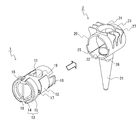
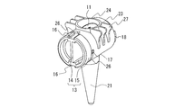
- FIG. 8 and 9 show another example of the container of the present invention.
- FIG. 8 is an exploded perspective view of the container of this example
- FIG. 9 is a perspective view of the container of this example.
- the same parts as those in FIGS. 1 to 7 are denoted by the same reference numerals.
- the container of the present example further includes a rotation operation ring 15, an open / close recognition unit 16 (device switch), a stop unit 17, a latching unit 18, and a support plate 19 on the lid 1.
- the sealing position 12 is formed in a thin plate shape, and a rib surface 25 and a rotation adjusting portion 26 are further arranged on the container body 2. Except for these, the configuration is the same as in Example 1 and Example 2, and the usage pattern is the same except for the following.
- the rotation operation ring 15 is formed as the rotation operation unit 13 in addition to the linear rotation operation unit 14.
- the rotation operation ring 15 is provided around an outer peripheral edge on one end side of the lid body 1, and contacts the one end of the lid body housing portion 23 when the lid body 1 is inserted into the lid body housing portion 23. It is formed to touch.
- the rotary operation ring 15 is formed with two concave open / close recognizing portions 16 with the peripheral edges partially cut away symmetrically.
- the shape of the open / close recognition unit 16 is not particularly limited, and examples thereof include a convex shape and a concave shape.
- the number of the open / close recognition units 16 is not particularly limited, and may be one, for example, or two or more.
- the hooking portion 18 is formed on the opposite side of the rotation operation ring 15 by cutting the outer peripheral edge of the lid 1 at two locations, and the end portion between the cuts protrudes outward. And formed. Two hooking portions 18 are provided symmetrically on the outer peripheral edge (only one is shown in the figure). In a state where the lid body 1 is accommodated in the lid body accommodating portion 23, the protruding portion of the latching portion 18 is latched so as to be movable along the outer peripheral edge on one end side of the lid body accommodating portion 23.
- the said cover body 1 can be rotated stably, without the position of the said through-hole 11, the said side wall opening part 24, and the said top opening 22 shifting
- two stop portions 17 are formed symmetrically in contact with the rotation operation ring 15 (only one is shown in the figure).
- a support plate 19 is disposed inside the lid body 1 except for the through-hole 11 portion in order to increase the physical strength of the lid body 1.
- the number of the sealing positions 12 is two as in the first and second embodiments. However, in the container of the present invention, the number of the sealing positions is not limited to two. Moreover, in the container of this example, the number of the said latching
- the rotation adjusting portion 26 is formed by cutting out a quarter of the peripheral edge of the lid housing portion 23 into a strip shape.
- the number of the rotation adjusting units is not particularly limited, and may be one, for example, or two or more.
- a slightly raised rib surface 25 is formed in parallel to the axial direction on the inner peripheral surface of the lid housing portion 23 adjacent to the upper opening 22. In the sealed state, when the sealing position 12 presses the rib surface 25 outward, the container of this example can obtain higher sealing performance and strength.
- the rib surface is not limited to the inner peripheral surface of the lid housing portion adjacent to the upper opening, and further, for example, the inner circumference of the lid housing portion adjacent to the side wall opening. It may be formed on the surface. By forming the rib surface also on the side wall opening side, the container of the present invention can obtain higher sealing performance and strength.
- the container of this example is used as follows, for example.
- the lid body 1 is rotatably inserted into one end opening side of the lid body accommodating portion 23.
- FIG. 10 shows a top view of the container during opening and closing and during opening and closing.
- 10A is a top view of the container when the lid is opened
- FIG. 10B is a state during opening and closing
- FIG. 10C is a top view of the container when sealed.
- the upper opening 22 and the side wall opening 24 are communicated with each other through the through hole 11, and the container is opened.
- the stop portion 17 is disposed at the left end of the rotation adjusting portion 26 in the figure, and can move in the right direction (turned clockwise when viewed from the rotation operation ring 15 side) in the drawing.
- FIG. 5B the through hole formed in the lid 1 by rotating the linear rotation operation portion 14 (not shown) or the rotation operation ring 15 clockwise.
- the lid body 1 rotates clockwise.
- one of the two sealing positions 12 starts to cover the side wall opening 24.
- FIG. 3C when the lid body 1 is rotated 90 degrees (1/4 of the entire circumference of the lid body 1), two sealing positions 12 are formed in the upper opening 22 (not shown). And the side wall opening 24 are simultaneously sealed to seal the container.
- the stopping portion 17 reaches the right end of the rotation adjusting portion 26 in the figure, and therefore does not rotate further in the clockwise direction.
- the rotation adjusting unit 26 and the stop unit 17 are provided as described above, so that the rotation operation is limited to 90 degrees, and the fully opened state and the sealed state are achieved. Is easy to switch. Therefore, the automatic analyzer using the container of this example can automatically open and close the container only by providing a mechanism for rotating the linear rotation operation unit 14 as a container opening and closing mechanism.
- the automatic analyzer using the container of this example can use the positions of the two opening / closing recognition units 16 as container opening / closing signals. Therefore, the automatic analyzer has a mechanism for recognizing the position of the concave open / close recognition unit 16 and has a mechanism for judging the open / close state of the container according to the above-described position, thereby confirming the open / closed state of the container. Is possible.
- FIG. 1 In FIG. 1
- FIG. 11 is the schematic diagram when the opened state is recognized
- FIG. 11B is the schematic diagram when the sealed state is recognized
- FIGS. 11A and 11B are schematic views of the lid body 1 as viewed from the direction of the rotation axis, and the arrow in the rotation direction in FIG. 11A indicates the rotation direction of the lid body 1.
- the left and right arrows in both figures indicate the moving direction of the terminal 41 of the automatic analyzer.
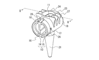
- FIG. 12 to 15 show another example of the container of the present invention.
- 12 is an exploded perspective view of the container of the present example
- FIG. 13 is a perspective view of the container of the present example
- FIG. 14 is a perspective view of the lid body 1 before the O-ring 32 is mounted in the container of the present example.
- FIG. FIG. 15 is a cross-sectional view of the container of this example as seen from the direction II-II in FIG. 12 to 15, the same parts as those in FIGS. 1 to 11 are denoted by the same reference numerals.
- annular groove 31 is further formed at the sealing position 12 of the lid 1, and an annular O-ring 32 is attached to the annular groove 31.
- the annular groove 31 is formed so as to be disposed at a position surrounding the upper surface opening 22 at the time of sealing. Except for these, the configuration is the same as in the first to third embodiments, and the usage pattern is the same except for the following.
- the number of the annular grooves 31 is not particularly limited, and may be one or more, for example.
- the material of the O-ring 32 is not particularly limited, and examples thereof include nitrile rubber, fluorine rubber, silicone rubber, and Teflon (registered trademark).
- the container of this example is used as follows, for example.
- the lid 1 is rotatably inserted into the lid housing portion 23 from one end opening side thereof.
- FIG. 15A is a cross-sectional view of the container in this example in an open state
- FIG. 15B is a cross-sectional view of the container in this example in a sealed state.
- the upper opening 22 and the side wall opening 24 are communicated with each other through the through hole 11, and the container is opened.
- the sealing position 12 formed on the lid 1 is rotated clockwise by rotating the rotation operation unit 13 (not shown) clockwise.
- the O-ring 32 attached to the annular groove 31 is attached to the lid housing portion 23.
- the container of this example is in close contact with the inner peripheral surface (see FIG. 15B).
- the O-ring 32 comes into close contact with the inner peripheral surface of the lid housing portion 23, whereby the container of this example can obtain higher sealing performance.
- the container of this example can further improve the sealing performance by including the above-described configuration in addition to the configuration of the third embodiment.
- the container of the present invention can be easily opened and closed without attaching or detaching the lid, so that it can be easily applied to an automatic analyzer.
- the container of the present invention is also excellent in sealing properties. Therefore, the use of the container of the present invention is not limited, and can be preferably used in a wide range of fields such as genetic engineering, biochemistry, physics and chemistry, and medicine.
Landscapes
- Engineering & Computer Science (AREA)
- General Engineering & Computer Science (AREA)
- Health & Medical Sciences (AREA)
- Chemical & Material Sciences (AREA)
- General Health & Medical Sciences (AREA)
- Mechanical Engineering (AREA)
- Analytical Chemistry (AREA)
- Chemical Kinetics & Catalysis (AREA)
- Life Sciences & Earth Sciences (AREA)
- Clinical Laboratory Science (AREA)
- Hematology (AREA)
- Veterinary Medicine (AREA)
- Immunology (AREA)
- Pathology (AREA)
- General Physics & Mathematics (AREA)
- Biochemistry (AREA)
- Physics & Mathematics (AREA)
- Public Health (AREA)
- Animal Behavior & Ethology (AREA)
- Pharmacology & Pharmacy (AREA)
- Automatic Analysis And Handling Materials Therefor (AREA)
- Closures For Containers (AREA)
- Sampling And Sample Adjustment (AREA)
- Apparatus Associated With Microorganisms And Enzymes (AREA)
Abstract
Description
本発明の容器の一例を図1から図4に示す。図1は、本例の容器の分解斜視図である。図2は、本例の容器の斜視図である。図3は、図2におけるI-I方向から見た本例の容器の断面図である。図4(A)は、前記容器体の断面図であり、図4(B)は、前記蓋体の断面図である。前記図1から図4において、同一部分には同一符号を付している。
図6および図7に、本発明の容器の別の一例を示す。図6は、本例の容器の分解斜視図であり、図7は、本例の容器の斜視図である。前記両図において、図1から図5と同一部分には同一符号を付している。
図8および図9に、本発明の容器の別の一例を示す。図8は、本例の容器の分解斜視図であり、図9は、本例の容器の斜視図である。前記両図において、図1から図7と同一部分には同一符号を付している。
図12~図15に、本発明の容器の別の一例を示す。図12は、本例の容器の分解斜視図であり、図13は、本例の容器の斜視図であり、図14は、本例の容器における、Oリング32装着前の蓋体1の斜視図である。図15は、図13におけるII-II方向から見た本例の容器の断面図である。前記図12~図15において、図1から図11と同一部分には同一符号を付している。
Claims (15)
- 容器体および蓋体を有する容器であって、
前記容器体は、上部開口かつ有底の筒状の容器本体と、少なくとも一端が開口の筒状の蓋体収容部とを有し、
前記容器本体の軸方向と前記蓋体収容部の軸方向が略垂直になる状態で、前記容器本体の上部開口に前記蓋体収容部が配置されて、前記容器本体と前記蓋体収容部が一体化され、
前記上部開口を介して、前記容器本体の内部と、前記蓋体収容部内部とが連通し、
前記容器本体の上部開口の上方に相当する前記蓋体収容部の側壁に開口部が形成され、
前記蓋体は、柱状であり、前記柱状の軸方向に対し垂直方向の貫通孔と、前記貫通孔の開口部の位置から周方向にずれた位置に封止位置とを有し、
前記蓋体は、前記蓋体収容部の内部に、前記蓋体の外周面が前記蓋体収容部の内周面と接した状態で、同軸的かつ回転可能に収容可能であり、
前記蓋体の貫通孔は、前記蓋体が、前記蓋体収容部に収容された状態で、前記蓋体収容部の側壁開口部と前記容器本体の上部開口とが位置する位置に相当する位置に配置されるように形成され、
前記蓋体が、前記蓋体収容部に収容された状態で、前記蓋体が回転して前記貫通孔の一端が前記側壁開口部の下に位置し、前記貫通孔の他端が前記容器本体の上部開口の上に位置することで、前記貫通孔を介して、前記容器本体内部と前記側壁開口部が連通し、
前記蓋体が回転して前記封止位置が前記容器本体の上部開口の上に位置することで、前記容器本体内部を外部から封止する容器。 - 前記蓋体収容部が、円筒状であり、前記蓋体が、円柱状であり、前記蓋体において、前記封止位置が、互いに、蓋体の径方向において対向する位置に2つ配置され、前記蓋体収容部の軸方向に対し垂直方向の、前記蓋体収容部の内径Xと、前記2つの封止位置の径方向における前記蓋体の外径Yとが、Y>Xの関係を満たす請求の範囲1記載の容器。
- 前記封止位置が、薄板状または前記上部開口に嵌合する凸形状である請求の範囲1記載の容器。
- 前記上部開口に隣接する前記蓋体収容部の内周面に、リブ面を有する請求の範囲1記載の容器。
- 前記蓋体収容部の内径Xと、前記2つの封止位置の径方向における前記蓋体の外径Yとが、X<Y<1.5Xの関係を満たす請求の範囲2記載の容器。
- 前記蓋体の少なくとも一端に、前記蓋体を回転操作する回転操作部が形成された請求の範囲1記載の容器。
- 前記回転操作部が、直線状に形成された請求の範囲6記載の容器。
- 前記蓋体収容部の外周面に、保持部が形成された請求の範囲1記載の容器。
- 前記蓋体収容部の少なくとも一端に、周縁の一部を帯状に切欠した回転調節部が形成され、前記蓋体の少なくとも一端側の外周面に、停止部が形成され、前記蓋体の回転操作時に、前記停止部が、前記回転調節部内のみで回転移動可能である請求の範囲1記載の容器。
- 前記蓋体の一端の外周縁の一部に、掛止部が形成されている請求の範囲1記載の容器。
- 前記蓋体の少なくとも一端に、開閉認識部が形成されている請求の範囲1記載の容器。
- 前記容器体および前記蓋体が、プラスチック製である請求の範囲1記載の容器。
- 分析に使用する分析容器であって、前記容器が請求の範囲1記載の容器であることを特徴とする分析容器。
- 前記分析が遺伝子分析である請求の範囲13記載の分析容器。
- 前記遺伝子分析がPCRによる分析である請求の範囲14記載の分析容器。
Priority Applications (5)
| Application Number | Priority Date | Filing Date | Title |
|---|---|---|---|
| US12/741,321 US20100255563A1 (en) | 2008-02-07 | 2009-02-07 | Container and analysis container using the same |
| EP09708014.7A EP2199802B1 (en) | 2008-02-07 | 2009-02-07 | Container and use thereof in an analysis |
| CN2009800001730A CN101680907B (zh) | 2008-02-07 | 2009-02-07 | 容器及采用该容器的分析容器 |
| JP2009524833A JP5190058B2 (ja) | 2008-02-07 | 2009-02-07 | 容器およびそれを用いた分析容器 |
| KR1020097017289A KR101226393B1 (ko) | 2008-02-07 | 2009-02-07 | 용기 및 이를 이용한 분석 용기 |
Applications Claiming Priority (2)
| Application Number | Priority Date | Filing Date | Title |
|---|---|---|---|
| JP2008-027392 | 2008-02-07 | ||
| JP2008027392 | 2008-02-07 |
Publications (1)
| Publication Number | Publication Date |
|---|---|
| WO2009099223A1 true WO2009099223A1 (ja) | 2009-08-13 |
Family
ID=40952290
Family Applications (1)
| Application Number | Title | Priority Date | Filing Date |
|---|---|---|---|
| PCT/JP2009/052119 Ceased WO2009099223A1 (ja) | 2008-02-07 | 2009-02-07 | 容器およびそれを用いた分析容器 |
Country Status (6)
| Country | Link |
|---|---|
| US (1) | US20100255563A1 (ja) |
| EP (1) | EP2199802B1 (ja) |
| JP (1) | JP5190058B2 (ja) |
| KR (1) | KR101226393B1 (ja) |
| CN (1) | CN101680907B (ja) |
| WO (1) | WO2009099223A1 (ja) |
Citations (2)
| Publication number | Priority date | Publication date | Assignee | Title |
|---|---|---|---|---|
| JPS51146981A (en) * | 1975-06-10 | 1976-12-16 | Kondo Hiroatsu | Lid of vessel |
| JP2006189346A (ja) * | 2005-01-06 | 2006-07-20 | Olympus Corp | 薬液容器、薬液保冷庫および培養処理装置 |
Family Cites Families (10)
| Publication number | Priority date | Publication date | Assignee | Title |
|---|---|---|---|---|
| US3603471A (en) * | 1969-11-24 | 1971-09-07 | Precision Sampling Corp | Septum valves |
| US4358111A (en) * | 1981-04-02 | 1982-11-09 | Air Products And Chemicals, Inc. | Pressurized, non-refillable recreation ball inflated with sulfur hexafluoride |
| US4395382A (en) * | 1981-09-25 | 1983-07-26 | Miskinis Robert J | Glassware stopcock with freeze extractor |
| DE3402276C1 (de) * | 1984-01-24 | 1985-02-21 | Eppendorf Gerätebau Netheler + Hinz GmbH, 2000 Hamburg | Reaktionsgefaess aus Kunststoff fuer kleine Fluessigkeitsmengen |
| JP3075569B2 (ja) * | 1990-09-06 | 2000-08-14 | アサマ化成株式会社 | 嫌気性菌の増殖細胞量の測定方法 |
| US6152189A (en) * | 1993-03-30 | 2000-11-28 | Isco, Inc. | Sampler |
| US6350415B1 (en) * | 1997-09-12 | 2002-02-26 | Becton, Dickinson And Company | Ball and socket closure for specimen collection container incorporating a dimple locking mechanism |
| US7700046B2 (en) * | 2004-09-14 | 2010-04-20 | Goldenberg Alec S | Controlled additive/reactant delivery system |
| JP2007015446A (ja) * | 2005-07-05 | 2007-01-25 | Nissan Motor Co Ltd | 給油構造 |
| JP4642587B2 (ja) * | 2005-08-04 | 2011-03-02 | ベックマン コールター, インコーポレイテッド | 試薬用容器の蓋構造 |
-
2009
- 2009-02-07 CN CN2009800001730A patent/CN101680907B/zh active Active
- 2009-02-07 EP EP09708014.7A patent/EP2199802B1/en active Active
- 2009-02-07 US US12/741,321 patent/US20100255563A1/en not_active Abandoned
- 2009-02-07 JP JP2009524833A patent/JP5190058B2/ja active Active
- 2009-02-07 WO PCT/JP2009/052119 patent/WO2009099223A1/ja not_active Ceased
- 2009-02-07 KR KR1020097017289A patent/KR101226393B1/ko active Active
Patent Citations (2)
| Publication number | Priority date | Publication date | Assignee | Title |
|---|---|---|---|---|
| JPS51146981A (en) * | 1975-06-10 | 1976-12-16 | Kondo Hiroatsu | Lid of vessel |
| JP2006189346A (ja) * | 2005-01-06 | 2006-07-20 | Olympus Corp | 薬液容器、薬液保冷庫および培養処理装置 |
Also Published As
| Publication number | Publication date |
|---|---|
| KR20090115154A (ko) | 2009-11-04 |
| US20100255563A1 (en) | 2010-10-07 |
| CN101680907A (zh) | 2010-03-24 |
| CN101680907B (zh) | 2013-06-05 |
| JP5190058B2 (ja) | 2013-04-24 |
| EP2199802B1 (en) | 2017-08-02 |
| EP2199802A4 (en) | 2011-10-05 |
| KR101226393B1 (ko) | 2013-01-24 |
| EP2199802A1 (en) | 2010-06-23 |
| JPWO2009099223A1 (ja) | 2011-06-02 |
Similar Documents
| Publication | Publication Date | Title |
|---|---|---|
| KR101377732B1 (ko) | 점성화장재료용 용기 | |
| US7648037B2 (en) | Lid structure of reagent container | |
| US20070080093A1 (en) | Vial for test strips | |
| WO1998003410A1 (en) | Ball and socket closure | |
| US20090022631A1 (en) | Sample container | |
| KR20100040887A (ko) | 막 및 회전 가능한 보호 캡을 갖는 클로저 | |
| JP2008128776A (ja) | 蓋付き容器 | |
| WO2012100464A1 (zh) | 一种快速检测装置 | |
| JP5190058B2 (ja) | 容器およびそれを用いた分析容器 | |
| KR20140140853A (ko) | 화장용 튜브용기 | |
| US6109484A (en) | Dropping container | |
| WO2008114905A1 (en) | Dehumidifying structure for container cap | |
| JP5195284B2 (ja) | 試薬容器のキャップ構造および試薬の分取方法 | |
| JP7689959B2 (ja) | 検査チップおよび液体導入方法 | |
| JP7486456B2 (ja) | スポイト容器 | |
| CN215917455U (zh) | 用于离心管的管盖及离心管套件 | |
| US20240091768A1 (en) | Liquid handling system | |
| CN215963621U (zh) | 样本容器 | |
| CN217180937U (zh) | 采样管 | |
| KR200295696Y1 (ko) | 용기용 원터치 캡 | |
| CN218807897U (zh) | 一种容器 | |
| WO2008041341A1 (fr) | Capuchon de récipient de réactif et récipient de réactif | |
| JP2018191778A (ja) | コンパクト容器 | |
| JP2021167212A (ja) | 容器 | |
| JP3186815U (ja) | 栓体 |
Legal Events
| Date | Code | Title | Description |
|---|---|---|---|
| WWE | Wipo information: entry into national phase |
Ref document number: 200980000173.0 Country of ref document: CN |
|
| WWE | Wipo information: entry into national phase |
Ref document number: 2009524833 Country of ref document: JP |
|
| WWE | Wipo information: entry into national phase |
Ref document number: 1020097017289 Country of ref document: KR |
|
| 121 | Ep: the epo has been informed by wipo that ep was designated in this application |
Ref document number: 09708014 Country of ref document: EP Kind code of ref document: A1 |
|
| REEP | Request for entry into the european phase |
Ref document number: 2009708014 Country of ref document: EP |
|
| WWE | Wipo information: entry into national phase |
Ref document number: 2009708014 Country of ref document: EP |
|
| WWE | Wipo information: entry into national phase |
Ref document number: 12741321 Country of ref document: US |
|
| NENP | Non-entry into the national phase |
Ref country code: DE |