WO2009104316A1 - 画像処理装置および画像処理プログラム - Google Patents
画像処理装置および画像処理プログラム Download PDFInfo
- Publication number
- WO2009104316A1 WO2009104316A1 PCT/JP2008/071049 JP2008071049W WO2009104316A1 WO 2009104316 A1 WO2009104316 A1 WO 2009104316A1 JP 2008071049 W JP2008071049 W JP 2008071049W WO 2009104316 A1 WO2009104316 A1 WO 2009104316A1
- Authority
- WO
- WIPO (PCT)
- Prior art keywords
- image
- images
- movement
- motion
- image processing
- Prior art date
- Legal status (The legal status is an assumption and is not a legal conclusion. Google has not performed a legal analysis and makes no representation as to the accuracy of the status listed.)
- Ceased
Links
Images





Classifications
-
- A—HUMAN NECESSITIES
- A61—MEDICAL OR VETERINARY SCIENCE; HYGIENE
- A61B—DIAGNOSIS; SURGERY; IDENTIFICATION
- A61B1/00—Instruments for performing medical examinations of the interior of cavities or tubes of the body by visual or photographical inspection, e.g. endoscopes; Illuminating arrangements therefor
- A61B1/04—Instruments for performing medical examinations of the interior of cavities or tubes of the body by visual or photographical inspection, e.g. endoscopes; Illuminating arrangements therefor combined with photographic or television appliances
- A61B1/041—Capsule endoscopes for imaging
-
- A—HUMAN NECESSITIES
- A61—MEDICAL OR VETERINARY SCIENCE; HYGIENE
- A61B—DIAGNOSIS; SURGERY; IDENTIFICATION
- A61B1/00—Instruments for performing medical examinations of the interior of cavities or tubes of the body by visual or photographical inspection, e.g. endoscopes; Illuminating arrangements therefor
- A61B1/00002—Operational features of endoscopes
- A61B1/00004—Operational features of endoscopes characterised by electronic signal processing
- A61B1/00009—Operational features of endoscopes characterised by electronic signal processing of image signals during a use of endoscope
-
- G—PHYSICS
- G06—COMPUTING OR CALCULATING; COUNTING
- G06T—IMAGE DATA PROCESSING OR GENERATION, IN GENERAL
- G06T7/00—Image analysis
- G06T7/20—Analysis of motion
- G06T7/223—Analysis of motion using block-matching
- G06T7/231—Analysis of motion using block-matching using full search
-
- G—PHYSICS
- G06—COMPUTING OR CALCULATING; COUNTING
- G06T—IMAGE DATA PROCESSING OR GENERATION, IN GENERAL
- G06T2207/00—Indexing scheme for image analysis or image enhancement
- G06T2207/10—Image acquisition modality
- G06T2207/10068—Endoscopic image
-
- G—PHYSICS
- G06—COMPUTING OR CALCULATING; COUNTING
- G06T—IMAGE DATA PROCESSING OR GENERATION, IN GENERAL
- G06T2207/00—Indexing scheme for image analysis or image enhancement
- G06T2207/30—Subject of image; Context of image processing
- G06T2207/30004—Biomedical image processing
- G06T2207/30028—Colon; Small intestine
Definitions
- the present invention relates to an image processing apparatus and an image processing program for sequentially displaying time-series images.
- a swallowable capsule endoscope has been proposed.
- This capsule endoscope is swallowed from the patient's mouth, which is the subject for examination, introduced into the subject, and naturally discharged, such as the esophagus, stomach, small intestine, large intestine, etc. It moves inside the organ according to its peristaltic movement. Then, while moving inside the body, images in the body are sequentially captured at 2 to 4 (frame / sec), for example, and the captured image data is wirelessly transmitted to a receiving apparatus outside the body. Images inside the subject taken by the capsule endoscope and received by the external receiving device are sequentially displayed in time series on a diagnosis workstation or the like and confirmed by an observer such as a doctor.
- This capsule endoscope takes a huge number of images. For this reason, in a diagnostic workstation, etc., changes between images are detected based on the similarity between adjacent images in time series. By reducing the time and adjusting the display time of each image, the burden on the observer to observe the image is reduced.
- a technique is known in which a plurality of pixel areas are set in an image and the similarity between the images is determined by obtaining a motion vector of each pixel area between consecutive images in time series.
- a method is known in which similarity between images is determined based on whether or not the obtained motion vectors are aligned, and display of images with high similarity is skipped or displayed at high speed (see Patent Document 1). ).
- the moving direction of the capsule endoscope within the subject is not constant, and the capsule endoscope that has been slid to the right (translated) changes its sliding direction to the left or moves backward.
- the capsule endoscope that has been depressed falls back and moves forward, it moves while changing its direction.
- the moving direction of the image to be captured also changes.
- the present invention has been made in view of the above, and an image processing apparatus and an image processing capable of preventing an observer from overlooking display contents when displaying a time-series image and improving observation efficiency.
- the purpose is to provide a program.
- an image processing apparatus detects movement between images constituting the time-series image in an image processing apparatus that sequentially displays time-series images, and Motion direction change image extraction means for extracting an image whose movement direction changes based on the movement between the detected images, and the display speed of the image extracted by the movement direction change image extraction means and the vicinity image of the image, And display speed control means for controlling the display speed relatively lower than the display speed of other images.
- an image processing program detects a movement between images constituting the time-series image on a computer having a display unit that sequentially displays time-series images, and has the movement between the detected images.
- a motion direction change image extraction step for extracting an image whose motion direction changes, and a display speed of the image extracted by the motion direction change image extraction step and a neighboring image of the image compared to the display speed of other images.
- a display speed control step for controlling the display speed relatively low.
- the display speed of an image in which the direction of movement changes and the image near the image can be controlled to be relatively lower than the display speed of other images. It is possible to prevent situations in which content is overlooked. Therefore, it is possible to efficiently grasp the contents of the time-series image, and there is an effect that the observation efficiency is improved.
- FIG. 1 is a schematic diagram showing an overall configuration of an image processing system including an image processing apparatus according to the first embodiment.
- FIG. 2 is a block diagram illustrating a functional configuration of the image processing apparatus according to the first embodiment.
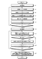
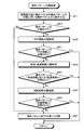
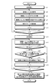
- FIG. 3 is a flowchart illustrating a processing procedure performed by the image processing apparatus according to the first embodiment.
- FIG. 4 is a diagram for explaining a motion vector calculation method.
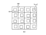
- FIG. 5 is a diagram for explaining a motion vector calculation method.
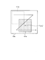
- FIG. 6 is a diagram for explaining matching.
- FIG. 7 is a flowchart showing a detailed processing procedure of the motion pattern classification process.
- FIG. 8 is a diagram illustrating an example of the image I (n).
- FIG. 9 is a diagram illustrating an example of the image I (n).
- FIG. 8 is a diagram illustrating an example of the image I (n).
- FIG. 10 is a diagram illustrating an example of the image I (n).
- FIG. 11 is a diagram illustrating an example of the image I (n).
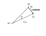
- FIG. 12 is a diagram illustrating a method for determining the rotation direction.
- FIG. 13 is a diagram illustrating a method for determining the rotation direction.
- FIG. 14 is a flowchart illustrating a processing procedure of the image processing apparatus according to the modification.
- FIG. 15 is a diagram for explaining extraction processing of a motion direction change image in the modification.
- FIG. 16 is a block diagram illustrating a functional configuration of the image processing apparatus according to the second embodiment.
- FIG. 17 is a flowchart illustrating a processing procedure performed by the image processing apparatus according to the second embodiment.
- FIG. 18 is a diagram for explaining the grouping process.
- FIG. 19 is a flowchart showing a detailed processing procedure of the grouping processing.
- FIG. 20 is a diagram for explaining a method of determining a change in the movement direction.
- FIG. 21 is a diagram for explaining a method of determining a change in the movement direction.
- FIG. 22 is a diagram for explaining a method of determining a change in the movement direction.
- DESCRIPTION OF SYMBOLS 10 Capsule-type endoscope 30 Receiving device A1-An Receiving antenna 50 Portable recording medium 70, 70b Image processing device 710 External interface 720 Input unit 730 Display unit 740, 740b Storage unit 741, 741b Image processing program 750, 750b Calculation Unit 751, 751b motion direction change image extraction unit 752 motion vector calculation unit 753 block division unit 754 motion pattern classification unit 755, 758 motion direction change determination unit 756 grouping unit 757 group determination unit 760 control unit 761 image display control unit 763 display Speed control unit 1 Subject
- FIG. 1 is a schematic diagram showing an overall configuration of an image processing system including an image processing apparatus 70 according to the first embodiment.
- the image processing system receives a capsule endoscope 10 that captures an image of the inside of the body of the subject 1 and receives image data that is wirelessly transmitted from the capsule endoscope 10.
- the apparatus 30 includes an image processing apparatus 70 that performs image processing on an image received by the receiving apparatus 30.
- a portable recording medium (portable recording medium) 50 is used for transferring image data between the receiving device 30 and the image processing device 70.
- the capsule endoscope 10 has an imaging function, a wireless function, an illumination function for illuminating an imaging site, and the like, and is taken from the mouth of the subject 1 such as a person or an animal for examination, for example. And introduced into the subject 1. Until it is spontaneously discharged, images inside the esophagus, stomach, small intestine, large intestine, and the like are sequentially captured at a predetermined imaging rate and acquired, and wirelessly transmitted outside the body.
- the image captured by the capsule endoscope 10 shows mucous membranes, contents floating in the body cavity, bubbles and the like, and sometimes important parts such as lesions.
- the passing speed of the capsule endoscope 10 in the body is not constant, and the time-series images to be captured are variously changed, such as an image that varies greatly or a similar image continues.
- the aerial image captured by the capsule endoscope 10 is a color image having a pixel level (pixel value) for each color component of R (red), G (green), and B (blue) at each pixel position. It is.
- the receiving device 30 includes a plurality of receiving antennas A1 to An, and receives image data wirelessly transmitted from the capsule endoscope 10 via the receiving antennas A1 to An.
- the receiving device 30 is configured so that the portable recording medium 50 can be freely attached and detached, and sequentially stores the received image data in the portable recording medium 50. In this way, the receiving apparatus 30 accumulates the images inside the subject 1 captured by the capsule endoscope 10 in the portable recording medium 50 in chronological order.
- the receiving antennas A1 to An are constituted by, for example, loop antennas, and are distributed at predetermined positions on the body surface of the subject 1 as shown in FIG. Specifically, for example, they are distributed and arranged at positions on the body surface corresponding to the passage route of the capsule endoscope 10 in the subject 1.
- the receiving antennas A1 to An may be arranged in a distributed manner on a jacket worn by the subject 1. In this case, the receiving antennas A1 to An are placed on the body surface of the subject 1 corresponding to the passage path of the capsule endoscope 10 in the subject 1 when the subject 1 wears this jacket. It is arranged at a predetermined position. Further, one or more receiving antennas may be arranged with respect to the subject 1, and the number thereof is not limited.
- the image processing apparatus 70 is realized by a general-purpose computer such as a workstation or a personal computer, and is configured so that the portable recording medium 50 can be freely attached and detached.
- the image processing device 70 acquires time-series images stored in the portable recording medium 50 and sequentially displays the acquired time-series images on a display such as an LCD or an ELD.
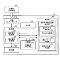
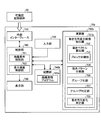
- FIG. 2 is a block diagram illustrating a functional configuration of the image processing apparatus 70 according to the first embodiment.
- the image processing apparatus 70 includes an external interface 710, an input unit 720, a display unit 730, a storage unit 740, a calculation unit 750, and a control unit 760 that controls the operation of the entire image processing apparatus 70.
- an external interface 710 an input unit 720, a display unit 730, a storage unit 740, a calculation unit 750, and a control unit 760 that controls the operation of the entire image processing apparatus 70.
- the external interface 710 is for acquiring image data of a time-series image captured by the capsule endoscope 10 and received by the receiving device 30.
- the portable recording medium 50 is detachably attached to the external interface 710.
- the reader is configured to read image data stored in the portable recording medium 50.
- the image data of the time-series images read by the external interface 710 is held in the storage unit 740, processed by the calculation unit 750, and sequentially displayed on the display unit 730 under the control of the control unit 760.
- the acquisition of the time-series image captured by the capsule endoscope 10 is not limited to the configuration using the portable recording medium 50.
- a server may be separately installed instead of the portable recording medium 50, and time series images may be stored in advance on this server.
- the external interface is configured by a communication device or the like for connecting to the server. Then, data communication with the server via this external interface may be performed to acquire a time series image.
- a time series image captured by the capsule endoscope 10 may be stored in the storage unit 740 in advance, and read from the storage unit 740 to acquire the time series image.
- the input unit 720 is realized by, for example, a keyboard, a mouse, a touch panel, various switches, and the like, and outputs input instruction information to the control unit 760.
- the display unit 730 is realized by a display device such as an LCD or an ELD, and displays various screens including a time-series image display screen under the control of the control unit 760.
- the storage unit 740 is realized by various IC memories such as ROM and RAM such as flash memory that can be updated and stored, a hard disk connected with a built-in or data communication terminal, an information storage medium such as a CD-ROM, and a reading device thereof.
- a program relating to the operation of the image processing apparatus 70, a program for realizing various functions provided in the image processing apparatus 70, data relating to execution of these programs, and the like are stored.
- an image processing program 741 for processing time-series images and sequentially displaying them on the display unit 730 is stored.
- the calculation unit 750 processes time-series images captured by the capsule endoscope 10 and performs various calculation processes for detecting a change in the movement direction between successive images.
- This calculation unit 750 detects movement between successive images and extracts an image whose movement direction changes (hereinafter referred to as “motion direction change image”), and changes the movement direction as a movement direction change image extraction unit.
- An image extraction unit 751 is included.
- This motion direction change image extraction unit 751 includes a motion vector calculation unit 752 as a motion vector calculation unit that calculates a motion vector between images for each block, and a motion pattern determination that classifies motion patterns according to the direction of the motion vector between images.
- the motion vector calculation unit 752 includes a block dividing unit 753 as a block dividing unit that divides an image into a plurality of blocks (area division).
- the control unit 760 is realized by hardware such as a CPU.
- the control unit 760 is based on image data of a time-series image acquired via the external interface 710, operation signals input from the input unit 720, programs and data stored in the storage unit 740, and the like.
- the operation of the entire image processing apparatus 70 is comprehensively controlled by giving instructions to each unit constituting the image, transferring data, and the like.
- the control unit 760 controls the image display control unit 761 that performs control to sequentially display the images constituting the time-series image on the display unit 730, and the motion direction extracted by the motion direction change image extraction unit 751 of the calculation unit 750.
- a display speed control unit 763 as display speed control means for controlling the display speed of the change image and its neighboring images relatively lower than the display speed of the other images.
- the calculation unit 750 initializes an image number n for identifying the time-series order of images to be processed (step a1). Then, the arithmetic unit 750 acquires the image I (n ⁇ 1) with the image number n ⁇ 1 and the image with the image number n from the time-series images acquired through the external interface 710 and stored in the storage unit 740. I (n) is acquired (step a3).
- the block dividing unit 753 divides the pixel space of each image data of the images I (n ⁇ 1) and I (n) into a plurality of blocks (pixel areas) (step a5).
- the size, number, etc. of each block may be set in advance, or may be configured to be changeable by a user operation, etc., but each block is evenly arranged in the pixel space by this block division. To do.
- the pixel space of each image data of the images I (n ⁇ 1) and I (n) is divided into 16 blocks of 4 ⁇ 4.
- the motion vector calculation unit 752 calculates a motion vector between the images I (n ⁇ 1) and I (n) for each corresponding block (step a7). For example, the motion vector calculation unit 752 calculates a motion vector using the normalized cross-correlation of the G components of the images I (n ⁇ 1) and I (n). The reason why the G component is used is that the sensitivity of the G component is the best among the RGB components, and the difference between the luminance components is likely to occur.
- 4 and 5 are diagrams for explaining a method of calculating a motion vector.
- FIG. 4 shows a pixel space of the image I (n ⁇ 1)
- FIG. 5 shows a pixel space of the image I (n). Is shown.
- the motion vector calculation unit 752 associates the template region 111 in the image I (n ⁇ 1) with the matching region 121 in the image I (n) in units of blocks.
- the motion vector calculation unit 752 sets a template region 111 in each block 110 of the image I (n ⁇ 1) as shown in FIG. For example, an area having a center (x i , y i ) at the center and a size (tx, ty) smaller than each block 110 is set as the template area 111 at the center of each block 110.
- i is a template area number.
- i 1 to 16.
- FIG. 6 is a diagram for explaining the matching, and shows how the matching area 121a is detected in the corresponding block 120a in the image I (n) using the pixel data of the template area 111a.
- an area most similar to the template area 111a is searched from the block 120a, and its normalized cross-correlation value is obtained.
- a region that most matches the template region 111a that is, a region having a high normalized cross-correlation value is detected as the matching region 121a.
- the center coordinates of the detected matching area 121a are (x a , y a ).
- a is a matching area number.
- the motion vector calculation unit 752 performs matching using the G component variance values of the template region and the matching region, and calculates a normalized cross-correlation value E according to the following equation (1).
- f (n, x, y) is image data of image number n.
- the motion vector calculation unit 752 performs matching for each block 120 and detects the matching region 121.
- the motion vector calculation unit 752 calculates the center coordinates (x) between the template region 111 of each block 110 of the image I (n ⁇ 1) and the matching region 121 in the corresponding block 120 of the image I (n). i, y i), is calculated as a motion vector changes in (x a, y a).
- the obtained matching result data is held in the storage unit 740. Specifically, the center coordinates of the obtained matching area, the normalized cross-correlation value E, the motion vector, and the like are stored in association with each template area number.
- the motion pattern classification unit 754 subsequently performs a motion pattern classification process to classify the motion pattern of the image I (n) (step a9).
- the classification of the motion pattern of the image I (n) is based on the motion vector between the images I (n ⁇ 1) and I (n).
- the motion pattern is “translation upper”, “translation upper left”, “translation left “Translation left bottom” “Parallel bottom” “Parallel bottom right” “Parallel right” “Parallel right” “Parallel top right” "Forward movement” "Backward movement” "Left rotation movement” "Right rotation movement” "Other” This is done by classifying it.
- FIG. 7 is a flowchart showing a detailed processing procedure of the motion pattern classification process.
- the motion pattern classification unit 754 uses the normalized cross-correlation value E obtained as a result of the matching performed in step a7 in FIG. 3 as the reliability of the motion vector between the images I (n ⁇ 1) and I (n). For a motion vector with low reliability, a process of excluding it from the motion vector used for motion pattern classification is performed as a matching failure (step a911). Subsequently, the motion pattern classification unit 754 determines whether to classify the motion pattern. For example, as a result of excluding motion vectors with low reliability, the motion pattern classification unit 754 has fewer than half the total number of motion vectors (eight or less in the first embodiment) that can be used for motion pattern classification.
- step a913 it is determined that the motion pattern is not classified (step a913: No), and the process proceeds to step a927 to classify the motion pattern of the image I (n) as “other”. This is because the number of matching failures is large, and it is considered that the reliability cannot be obtained even if the motion patterns are classified.
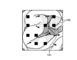
- FIG. 8 is a diagram illustrating an example of an image I (n).
- a motion vector 131 that can be used for classifying a motion pattern set with the image I (n ⁇ 1) is illustrated. Yes.
- the normalized cross-correlation value E obtained as a result of matching decreases.
- the motion pattern is classified as “others”.
- the motion pattern is classified as “other” when the motion vector that can be used for the motion pattern classification is less than half, the motion pattern need not be less than half, and the threshold value may be set as appropriate.
- the movement pattern classification unit 754 performs a process (parallel movement classification process) for classifying the movement pattern of the image I (n) as “parallel movement”.
- a process parallel movement classification process
- the motion pattern is “translation”
- the motion vectors between the images I (n ⁇ 1) and I (n) all have the same direction. Therefore, the motion pattern classifying unit 754 classifies the motion pattern of the image I (n) as “parallel movement” when the directions of the motion vectors are substantially the same.
- the motion pattern classification unit 754 obtains the variance of the direction of each motion vector, and classifies the motion pattern as “parallel movement” if the obtained variance value is smaller than a predetermined threshold value.
- FIG. 9 is a diagram illustrating an example of an image I (n).
- a motion vector 141 that can be used for classifying a motion pattern set with the image I (n ⁇ 1) is illustrated. Yes.
- the motion pattern is classified as “parallel movement”.
- the motion pattern classification unit 754 subsequently calculates the average direction of each motion vector, and “up”, “upper left”, “left”, “lower left”, “lower”, It is classified into one of “lower right”, “right”, and “upper right”.
- the motion patterns of the image I (n) classified as “translation” are further moved in different directions “translation upper”, “translation upper left”, “translation left”, “translation lower left”, “translation” It is classified into one of “down”, “lower right of translation”, “right of translation” and “upper right of translation”.
- step a917 Yes
- this process ends.
- the process returns to step a9 in FIG.
- step a917: No the motion pattern classification unit 754 classifies the motion pattern of the image I (n) into “forward movement” or “reverse movement” (forward / reverse movement classification process). (Step a919).
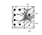
- FIG. 10 is a diagram illustrating an example of an image I (n).
- a motion vector 151 that can be used to classify a motion pattern set with the image I (n ⁇ 1) is illustrated. Yes.
- the motion pattern classification unit 754 sets straight lines 153 along the respective motion vectors 151 as indicated by broken lines in FIG. Voting points 155 are set at the intersections. Then, the movement pattern classification unit 754 classifies the movement pattern as “forward movement” or “reverse movement” when the set voting points 155 are concentrated within a predetermined coordinate range of a predetermined size, for example.
- the image I (n) is scanned to search for a coordinate range 157 that includes voting points equal to or greater than a predetermined reference voting point, and when searched, it is classified as “forward movement” or “backward movement”.
- the reference voting points can be set as appropriate, for example, more than half of the total number of voting points.
- the motion pattern classifying unit 754 averages the direction of each motion vector with respect to, for example, the average position of each vote point within the searched coordinate range. If it is in the direction of the position, it is “forward movement”, and if it is in the opposite direction, it is “backward movement”. For example, in the example of FIG. 10, each motion vector 151 faces in the opposite direction to the coordinate range 157 where the voting points 155 are concentrated, and is classified as “backward movement”. Actually, the position of the capsule endoscope 10 does not move, but the mucous membrane of the digestive tract contracts due to a peristaltic movement, and an image is obtained in which the capsule endoscope 10 moves forward or backward. Are also classified as “forward movement” or “backward movement”.
- step a921 it is determined whether or not the movement pattern of the image I (n) is classified as “forward movement” or “reverse movement”. If the movement pattern is classified (step a921: Yes). Then, this process is terminated and the process returns to step a9 in FIG. On the other hand, when not classified (step a921: No), the motion pattern classification unit 754 performs a process of classifying the motion pattern of the image I (n) into “rotation movement” (rotation movement classification process) (step a923).
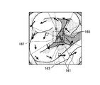
- FIG. 11 is a diagram illustrating an example of an image I (n).
- a motion vector 161 that can be used to classify a motion pattern set with the image I (n ⁇ 1) is illustrated. Yes.
- the motion pattern classification unit 754 sets straight lines 163 orthogonal to the respective motion vectors 161 as shown by broken lines in FIG. 11, and sets the straight lines 163 at positions where the straight lines 163 intersect with each other.
- a voting point 165 is set.
- the movement pattern classification unit 754 classifies the movement pattern as “rotation movement” when the set voting points 165 are concentrated within a predetermined coordinate range of a predetermined size, for example.
- the image I (n) is scanned to search for a coordinate range 167 including voting points equal to or more than a predetermined reference voting point, and when searched, it is classified as “rotation movement”.
- the reference voting points can be set as appropriate, for example, more than half of the total number of voting points.
- the motion pattern classification unit 754 subsequently sets, for example, the average position of each vote point within the searched coordinate range as the rotation center position. Then, the motion pattern classification unit 754 calculates, for each motion vector, an angle formed by each straight line connecting the start point and the end point with the rotation center position, and rotates depending on whether the obtained angle is a positive value or a negative value. The direction is classified as either “left” or “right”. 12 and 13 are diagrams for explaining a method of determining the rotation direction. As shown in FIG.
- step a925: Yes the motion pattern classification unit 754 proceeds to step a927 and classifies the motion pattern of the image I (n) as “other”. That is, the motion pattern classification unit 754 has no regularity in the direction of each motion vector in the image I (n), and the motion pattern between the images I (n ⁇ 1) and I (n) is “translation” “forward”.
- the motion pattern of the image I (n) is classified as “others” in step a927, and the process returns to step a9 in FIG.
- the motion patterns of the image I (n) classified by the motion pattern classification process are held in the storage unit 740.
- the movement direction change image extraction unit 751 extracts the image I (n) as a movement direction change image (step a21), and the process proceeds to step a23.
- the motion direction change determination unit 755 determines the similarity when the motion patterns of the images I (n ⁇ 1) and I (n) are different. The movement direction change determination unit 755 determines that the movement direction has not changed when the movement patterns are similar, and determines that the movement direction has changed when the movement patterns are dissimilar.
- the unit 763 sets a predetermined number of consecutive images around the movement direction change image extracted in step a21 as the vicinity image, and sets the display speed of the movement direction change image and the vicinity image to the display speed of other images. Control to make it relatively low is performed (step a27).
- the motion pattern of each image is classified based on the motion vector between the images constituting the time series image, and the motion direction is changed based on this motion pattern.
- Images can be extracted.
- sequentially displaying time-series images it is possible to control the display speed of an image whose direction of movement has changed and its neighboring images relatively lower than the display speed of other images.
- the observer can observe an image whose movement direction changes at a slower display speed than the other images.
- FIG. 14 is a flowchart illustrating a processing procedure of the image processing apparatus according to this modification.
- symbol is attached
- FIG. 14 is a flowchart illustrating a processing procedure of the image processing apparatus according to this modification.
- symbol is attached
- the motion direction change determination unit compares the motion patterns of the images I (n ⁇ 1) and I (n) in step a17 to change the motion direction. If the direction of motion has changed as a result of the determination (step a19: Yes), whether or not a predetermined number of images having the same motion pattern as image I (n-1) continues from image I (n-1) It is determined whether or not (step b20).
- the predetermined number a value of 2 or more may be set in advance and may be a fixed value, or may be configured to be changeable by a user operation or the like. And when not continuing (step b20: No), it transfers to step a23.
- the process proceeds to step a21, and the motion direction change image extraction unit extracts the image I (n) as the motion direction change image, and then proceeds to step a23.
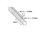
- FIG. 15 is a diagram for explaining the movement direction change image extraction processing in the present modification, and shows time-series images that are continuous from the back side to the near side in FIG.
- the motion pattern changes to “translation right” in image I (n).
- the image I (n) is extracted as a motion direction change image.
- the display speed of the image I (n) and a predetermined number of consecutive images before and after is reduced.
- FIG. 16 is a block diagram illustrating a functional configuration of the image processing device 70b according to the second embodiment.
- symbol is attached
- the image processing device 70b includes an external interface 710, an input unit 720, a display unit 730, a storage unit 740b, a calculation unit 750b, and a control unit 760 that controls operations of the entire image processing device 70b.
- the storage unit 740b stores an image processing program 741b.
- the calculation unit 750b includes a motion direction change image extraction unit 751b.
- the motion direction change image extraction unit 751b serves as a grouping unit, a motion vector calculation unit 752 having a block division unit 753, a motion pattern classification unit 754, and the like.
- the grouping unit 756 groups time-sequential image groups determined to have the same motion pattern.
- the group determination unit 757 determines whether the grouped adjacent group is a group composed of images that are equal to or more than a predetermined reference image number.
- the number of pre-reference images to be applied to the previous group and the number of post-reference images to be applied to the subsequent group are set in advance as the reference image number.
- the movement direction change determination unit 758 determines a change in movement direction between groups. Then, the motion direction change image extraction unit 751b extracts the first image in time series as the motion direction change image in the group in which the motion direction is determined to be changed by the motion direction change determination unit 758.
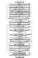
- FIG. 17 is a flowchart illustrating a processing procedure performed by the image processing apparatus 70b according to the second embodiment. Note that the processing described here is realized by the operation of each unit of the image processing apparatus 70b according to the image processing program 741b stored in the storage unit 740b. Further, the same processing steps as those shown in FIG. 3 in the first embodiment are denoted by the same reference numerals.
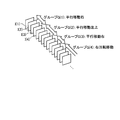
- FIG. 18 is a diagram for explaining the grouping process.
- the farthest side in FIG. 18 is the top (image number 1) image I (1), and shows time-series images continuous toward the front side. .
- time-sequential image groups determined to have the same motion pattern are grouped.
- the image groups of the images I (1) to I (4) whose motion patterns are classified as “parallel movement right” are grouped as a group G (1).
- the image pattern is classified as “translation upper left”
- the image pattern is “parallel”.
- Three images classified as “moving right” are grouped as group G (3), and after group G (3), the image patterns are classified as “rotating right” and grouped as group G (4).
- FIG. 19 is a flowchart showing a detailed processing procedure of the grouping process.
- the grouping unit 756 first initializes the image number n again (step d1), and registers the image I (n ⁇ 1) in the first group (step d3). Subsequently, the grouping unit 756 reads out and acquires the motion patterns of the images I (n ⁇ 1) and I (n) classified at step a9 in FIG. 17 from the storage unit 740b (step d5). Then, the grouping unit 756 compares the acquired motion patterns, and if the motion patterns are the same (step d7: Yes), the image I (n) is added to the group in which the image I (n ⁇ 1) is registered. Additional registration is performed (step d9).
- the grouped data (group information) of each group is held in the storage unit 740b. Specifically, the last image number in the group, the motion pattern (the motion pattern of the images constituting the group), and the like are stored in association with the serial number assigned to each group.
- the group determining unit 757 subsequently initializes a group number m for identifying the group to be processed (step c17). Then, the group determination unit 757 reads out and acquires the group information of the groups G (m ⁇ 1) and G (m) from the storage unit 740b (Step c19).
- the group determination unit 757 determines whether or not the number of images constituting the group G (m ⁇ 1) is equal to or greater than the number of pre-reference images.
- the number of images constituting the group G (m ⁇ 1) is obtained, for example, by subtracting the last image number in the group G (m ⁇ 2) from the last image number in the group G (m ⁇ 1). If the number of images before the reference is equal to or greater than the number of pre-reference images (step c21: Yes), the group determination unit 757 subsequently determines whether the number of images constituting the group G (m) is equal to or greater than the number of images after the reference.
- the number of images constituting the group G (m) is obtained, for example, by subtracting the last image number in the group G (m ⁇ 1) from the last image number in the group G (m).
- a value of 1 or more is preset for each of the number of pre-reference images and the number of post-reference images.
- Each value of the number of pre-reference images and the number of post-reference images may be a fixed value or may be configured to be changeable by a user operation or the like.
- the group determination unit 757 compares the motion patterns of the groups G (m ⁇ 1) and G (m) and determines the change in the motion direction. (Step c24). And as shown in FIG. 17, when a motion direction does not change (step c25: No), it transfers to step c27. At this time, when the motion pattern of the groups G (m ⁇ 1) and G (m) is “others”, the process may proceed to step c27 without performing the process of step c26 in the subsequent stage.
- step c25 when the movement direction has changed (step c25: Yes), the movement direction change image extraction unit 751b extracts the time-series head image in the group G (m) as a movement direction change image (step c26). ), And proceeds to step c27.
- 20 to 22 are diagrams for explaining a method of determining a change in the movement direction.
- this determination method among the movement patterns, “parallel movement”, “rotational movement”, “forward movement”, “reverse movement”, and “others” are set as parent patterns. Then, “Parallel movement upper”, “Parallel movement upper left”, “Parallel movement left”, “Parallel movement lower left”, “Parallel movement lower”, “Parallel movement lower right”, “Parallel movement right”, and “Translation upper right” are the parent patterns Is a child pattern for. In addition, “left rotation movement” and “right rotation movement” are child patterns with respect to the parent pattern “rotation movement”. For example, as shown in FIG.
- “upper” and “upper left”, “upper left” and “left”, “left” and “lower left”, “lower left” and “lower”, “lower” and “lower right”, “lower right” and “Right”, “Right” and “Upper right”, and “Upper right” and “Up” are defined as similar movement directions. Then, as shown in FIG. 21, when the child patterns of the movement patterns of the groups G (m ⁇ 1) and G (m) are “translation right” and “translation upper left” and the movement directions are dissimilar. Determines that the direction of movement has changed.
- the display speed of the first image 193 and a predetermined number of consecutive images before and after the time-series in the group G (m) is reduced.
- the child patterns of the movement patterns of groups G (m ⁇ 1) and G (m) are “translation right” and “translation upper right”, and the movement directions are similar. Is determined not to change the direction of movement. Therefore, when displaying time-series images, the display speed of the first image 195 in time series in the group G (m) and a predetermined number of consecutive images before and after is not reduced.
- the same effects as in the first embodiment can be obtained.
- the images constituting the time-series image it is possible to group a group of continuous images in time series determined to have the same motion pattern, and determine a change in motion direction in units of groups.
- a motion direction change image can be extracted on the condition that a predetermined number of the same motion patterns are continuous before and after the motion pattern change as well as the motion direction change.
- the present invention is not limited to this.
- the present invention can be applied in the same manner as long as sequential images are sequentially displayed.
- the image processing apparatus and the image processing program of the present invention are useful for efficiently observing images by preventing the observer from overlooking the display contents when displaying time-series images.
Landscapes
- Health & Medical Sciences (AREA)
- Life Sciences & Earth Sciences (AREA)
- Engineering & Computer Science (AREA)
- Surgery (AREA)
- Physics & Mathematics (AREA)
- Heart & Thoracic Surgery (AREA)
- General Health & Medical Sciences (AREA)
- Optics & Photonics (AREA)
- Pathology (AREA)
- Radiology & Medical Imaging (AREA)
- Biophysics (AREA)
- Biomedical Technology (AREA)
- Veterinary Medicine (AREA)
- Medical Informatics (AREA)
- Molecular Biology (AREA)
- Animal Behavior & Ethology (AREA)
- Nuclear Medicine, Radiotherapy & Molecular Imaging (AREA)
- Public Health (AREA)
- Signal Processing (AREA)
- Multimedia (AREA)
- Computer Vision & Pattern Recognition (AREA)
- General Physics & Mathematics (AREA)
- Theoretical Computer Science (AREA)
- Endoscopes (AREA)
- Image Analysis (AREA)
- Television Signal Processing For Recording (AREA)
Abstract
ある実施形態にかかる画像処理装置において、動き方向変化判定部(755)は、画像間の動き方向の変化を判定する。動き方向変化画像抽出部(751)は、動き方向が変化したと判定された画像を抽出する。そして、画像表示制御部(761)が、時系列画像を構成する各画像を時系列順に順次表示する制御を行うが、このとき、表示速度制御部(763)が、動き方向変化画像抽出部(751)によって抽出された画像およびこの画像と前後に連続する所定数の画像の表示速度を、その他の画像の表示速度に比べて相対的に低くする制御を行う。
Description
本発明は、時系列画像を順次表示する画像処理装置および画像処理プログラムに関するものである。
近年、内視鏡の分野において、被検体内部の画像を撮像する撮像機能や、撮像部によって撮像された画像データを無線送信する送信機能等がカプセル形状のケース内に収容されて構成された、飲込み型のカプセル型内視鏡が提案されている。このカプセル型内視鏡は、検査のため被検体である患者の口から飲込まれて被検体内部に導入され、自然排出されるまでの間、体内の例えば食道や胃、小腸、大腸等の臓器内部をその蠕動運動に従って移動する。そして、体内を移動中に、例えば2~4(frame/sec)で体内の画像を順次撮像し、撮像した画像データを体外の受信装置に無線送信する。このカプセル型内視鏡によって撮像されて体外の受信装置で受信された被検体内部の画像は、診断用のワークステーション等で時系列順に順次表示され、医師等の観察者によって確認される。
このカプセル型内視鏡は、膨大な枚数の画像を撮像する。このため、診断用のワークステーション等では、時系列で近傍する画像間の類似度をもとに画像間の変化を検出し、変化が激しければ表示時間を長く、変化が緩やかであれば表示時間を短くして各画像の表示時間を調整することによって観察者による画像の観察にかかる負担を軽減している。この種の技術としては、画像内に複数の画素領域を設定し、時系列で連続する画像間での各画素領域の動きベクトルを求めることによって画像の類似度を判定する技術が知られている。例えば、求めた各動きベクトルの向きが揃っているか否かによって画像間の類似度を判定し、類似度の高い画像の表示をスキップまたは高速に表示する手法が知られている(特許文献1参照)。
ところで、カプセル型内視鏡の被検体内での移動方向は一定ではなく、右方向にスライド(平行移動)していたカプセル型内視鏡がそのスライド方向を左方向に変えたり、後進移動していたカプセル型内視鏡が奥へ落ち込んで前進移動したりと、その方向を変えながら移動する。このため、撮像される画像の動き方向も変化する。この画像の動き方向の変化点では、他の画像よりも遅い表示速度で観察したいという要望があった。特に長時間の時系列画像の観察では、画像の動き方向が急激に変化するとその変化に対する認識が遅れてしまい、重要な情報を見逃してしまう事態が生じる可能性があるからである。またこのため、観察者は、見逃していないか遡って画像を見直して確認する等の作業を行っており、観察効率が低下してしまうという問題もあった。
本発明は、上記に鑑み為されたものであって、時系列画像を表示する場合の観察者による表示内容の見逃しの防止を図るとともに、観察効率を向上させることができる画像処理装置および画像処理プログラムを提供することを目的とする。
上記した課題を解決し、目的を達成するため、本発明にかかる画像処理装置は、時系列画像を順次表示する画像処理装置において、前記時系列画像を構成する画像間の動きを検出し、該検出した画像間の動きをもとに動き方向が変化する画像を抽出する動き方向変化画像抽出手段と、前記動き方向変化画像抽出手段によって抽出された画像および該画像の近傍画像の表示速度を、他の画像の表示速度に比べて相対的に低く制御する表示速度制御手段と、を備えることを特徴とする。
また、本発明にかかる画像処理プログラムは、時系列画像を順次表示する表示部を備えたコンピュータに、前記時系列画像を構成する画像間の動きを検出し、該検出した画像間の動きをもとに動き方向が変化する画像を抽出する動き方向変化画像抽出ステップと、前記動き方向変化画像抽出ステップによって抽出された画像および該画像の近傍画像の表示速度を、他の画像の表示速度に比べて相対的に低く制御する表示速度制御ステップと、を実行させることを特徴とする。
本発明に係る画像処理装置によれば、動き方向が変化する画像およびその近傍画像の表示速度を、他の画像の表示速度に比べて相対的に低く制御することができるので、観察者による表示内容の見逃しが発生する事態を防止できる。したがって、時系列画像の内容を効率良く把握することができ、観察効率が向上するという効果を奏することができる。
10 カプセル型内視鏡
30 受信装置
A1~An 受信用アンテナ
50 可搬型記録媒体
70,70b 画像処理装置
710 外部インターフェース
720 入力部
730 表示部
740,740b 記憶部
741,741b 画像処理プログラム
750,750b 演算部
751,751b 動き方向変化画像抽出部
752 動きベクトル算出部
753 ブロック分割部
754 動きパターン分類部
755,758 動き方向変化判定部
756 グループ化部
757 グループ判定部
760 制御部
761 画像表示制御部
763 表示速度制御部
1 被検体
30 受信装置
A1~An 受信用アンテナ
50 可搬型記録媒体
70,70b 画像処理装置
710 外部インターフェース
720 入力部
730 表示部
740,740b 記憶部
741,741b 画像処理プログラム
750,750b 演算部
751,751b 動き方向変化画像抽出部
752 動きベクトル算出部
753 ブロック分割部
754 動きパターン分類部
755,758 動き方向変化判定部
756 グループ化部
757 グループ判定部
760 制御部
761 画像表示制御部
763 表示速度制御部
1 被検体
以下、図面を参照し、本発明を実施するための最良の形態について詳細に説明する。なお、この実施の形態によって本発明が限定されるものではない。また、図面の記載において、同一部分には同一の符号を付して示している。
(実施の形態1)
図1は、実施の形態1における画像処理装置70を含む画像処理システムの全体構成を示す概略模式図である。なお、実施の形態1では、体内の管空内を移動するカプセル型内視鏡によって撮像された時系列画像を処理して表示する場合について説明する。図1に示すように、画像処理システムは、被検体1の体内の管空内の画像を撮像するカプセル型内視鏡10、カプセル型内視鏡10から無線送信される画像データを受信する受信装置30、受信装置30によって受信された画像を画像処理する画像処理装置70等を備える。受信装置30と画像処理装置70との間の画像データの受け渡しには、例えば可搬型の記録媒体(可搬型記録媒体)50が使用される。
図1は、実施の形態1における画像処理装置70を含む画像処理システムの全体構成を示す概略模式図である。なお、実施の形態1では、体内の管空内を移動するカプセル型内視鏡によって撮像された時系列画像を処理して表示する場合について説明する。図1に示すように、画像処理システムは、被検体1の体内の管空内の画像を撮像するカプセル型内視鏡10、カプセル型内視鏡10から無線送信される画像データを受信する受信装置30、受信装置30によって受信された画像を画像処理する画像処理装置70等を備える。受信装置30と画像処理装置70との間の画像データの受け渡しには、例えば可搬型の記録媒体(可搬型記録媒体)50が使用される。
カプセル型内視鏡10は、撮像機能や無線機能、撮像部位を照明する照明機能等を具備するものであって、例えば、検査のために人や動物等の被検体1の口から飲込まれて被検体1内部に導入される。そして、自然排出されるまでの間、食道、胃、小腸、大腸等の内部の画像を所定の撮像レートで順次撮像して取得し、体外に無線送信する。このカプセル型内視鏡10によって撮像される画像には、粘膜や、体腔内を浮遊する内容物、泡等が映るとともに、時として病変等の重要箇所が映る。また、体内でのカプセル型内視鏡10の通過速度は一定ではなく、撮像される時系列画像も大きく変化する画像が続いたり類似する画像が続いたりと様々である。なお、カプセル型内視鏡10によって撮像される管空内画像は、各画素位置においてR(赤),G(緑),B(青)の各色成分に対する画素レベル(画素値)を持つカラー画像である。
受信装置30は、複数の受信用アンテナA1~Anを備え、各受信用アンテナA1~Anを介してカプセル型内視鏡10から無線送信される画像データを受信する。この受信装置30は、可搬型記録媒体50の着脱が自在に構成されており、受信した画像データを可搬型記録媒体50に逐次保存する。このようにして、受信装置30は、カプセル型内視鏡10が撮像した被検体1内部の画像を時系列順に可搬型記録媒体50に蓄積する。
受信用アンテナA1~Anは、例えばループアンテナで構成され、図1に示すように、被検体1の体表上の所定位置に分散配置される。具体的には、例えば、被検体1内におけるカプセル型内視鏡10の通過経路に対応する体表上の位置に分散配置される。なお、受信用アンテナA1~Anは、被検体1に着用させるジャケットに分散配置されるものであってもよい。この場合には、受信用アンテナA1~Anは、被検体1がこのジャケットを着用することによって、被検体1内におけるカプセル型内視鏡10の通過経路に対応する被検体1の体表上の所定位置に配置される。また、受信用アンテナは、被検体1に対して1つ以上配置されればよく、その数は限定されない。
画像処理装置70は、ワークステーションやパソコン等の汎用コンピュータで実現されるものであり、可搬型記録媒体50の着脱が自在に構成される。この画像処理装置70は、可搬型記録媒体50に保存された時系列画像を取得し、取得した時系列画像を順次LCDやELD等のディスプレイに表示する。
図2は、実施の形態1における画像処理装置70の機能構成を説明するブロック図である。実施の形態1では、画像処理装置70は、外部インターフェース710と、入力部720と、表示部730と、記憶部740と、演算部750と、画像処理装置70全体の動作を制御する制御部760とを備える。
外部インターフェース710は、カプセル型内視鏡10で撮像され、受信装置30で受信した時系列画像の画像データを取得するためのものであり、例えば可搬型記録媒体50を着脱自在に装着し、この可搬型記録媒体50に保存された画像データを読み出すリーダ装置で構成される。この外部インターフェース710によって読み取られた時系列画像の画像データは、記憶部740に保持され、演算部750によって処理されて制御部760の制御のもと表示部730に順次表示される。なお、カプセル型内視鏡10によって撮像された時系列画像の取得は、可搬型記録媒体50を用いた構成に限定されるものではない。例えば、可搬型記録媒体50のかわりに別途サーバを設置し、このサーバに時系列画像を予め保存しておく構成としてもよい。この場合には、外部インターフェースを、サーバと接続するための通信装置等で構成する。そして、この外部インターフェースを介してサーバとデータ通信を行い、時系列画像を取得することとしてもよい。あるいは、記憶部740内にカプセル型内視鏡10によって撮像された時系列画像を予め保存しておき、記憶部740から読み出して時系列画像を取得する構成としてもよい。
入力部720は、例えばキーボードやマウス、タッチパネル、各種スイッチ等によって実現されるものであり、入力された指示情報を制御部760に出力する。表示部730は、LCDやELD等の表示装置によって実現されるものであり、制御部760の制御によって、時系列画像の表示画面を含む各種画面を表示する。
記憶部740は、更新記憶可能なフラッシュメモリ等のROMやRAMといった各種ICメモリ、内蔵或いはデータ通信端子で接続されたハードディスク、CD-ROM等の情報記憶媒体及びその読取装置等によって実現されるものであり、画像処理装置70の動作に係るプログラムや、画像処理装置70の備える種々の機能を実現するためのプログラム、これらプログラムの実行に係るデータ等が格納される。また、時系列画像を処理して順次表示部730に表示させるための画像処理プログラム741が格納される。
演算部750は、カプセル型内視鏡10によって撮像された時系列画像を処理し、連続する画像間の動き方向の変化を検出するための種々な演算処理を行う。この演算部750は、連続する画像間の動きを検出してその動き方向が変化する画像(以下、「動き方向変化画像」と呼ぶ。)を抽出する動き方向変化画像抽出手段としての動き方向変化画像抽出部751を含む。この動き方向変化画像抽出部751は、画像間の動きベクトルをブロック毎に算出する動きベクトル算出手段としての動きベクトル算出部752と、画像間の動きベクトルの向きに従って動きパターンを分類する動きパターン判定手段としての動きパターン分類部754と、画像間の動き方向の変化を判定する動き方向変化判定部755とで構成される。また、動きベクトル算出部752は、画像を複数のブロックにブロック分割(領域分割)するブロック分割手段としてのブロック分割部753を有する。
制御部760は、CPU等のハードウェアによって実現される。この制御部760は、外部インターフェース710を介して取得される時系列画像の画像データや入力部720から入力される操作信号、記憶部740に格納されるプログラムやデータ等に基づいて画像処理装置70を構成する各部への指示やデータの転送等を行い、画像処理装置70全体の動作を統括的に制御する。また、制御部760は、時系列画像を構成する各画像を表示部730に順次表示する制御を行う画像表示制御部761と、演算部750の動き方向変化画像抽出部751によって抽出された動き方向変化画像およびその近傍画像の表示速度を、その他の画像の表示速度に比べて相対的に低く制御する表示速度制御手段としての表示速度制御部763とを含む。
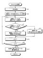
次に、実施の形態1の画像処理装置70が行う処理手順について、図3に示すフローチャートを参照して説明する。なお、ここで説明する処理は、記憶部740に格納された画像処理プログラム741に従って画像処理装置70の各部が動作することによって実現される。
図3に示すように、実施の形態1の画像処理装置70では、先ず演算部750が、処理対象の画像の時系列順序を識別するための画像番号nを初期化する(ステップa1)。そして、演算部750は、外部インターフェース710を介して取得されて記憶部740に格納された時系列画像の中から、画像番号n-1の画像I(n-1)と、画像番号nの画像I(n)とを取得する(ステップa3)。
続いて、ブロック分割部753が、画像I(n-1),I(n)の各画像データの画素空間を複数のブロック(画素領域)にブロック分割する(ステップa5)。各ブロックのサイズや数等は、予め設定しておくこととしてもよいし、ユーザ操作等によって設定変更可能に構成してもよいが、このブロック分割によって、各ブロックを画素空間上に均等に配置する。例えば、画像I(n-1),I(n)の各画像データの画素空間を、4×4の16個のブロックにブロック分割する。
次に、動きベクトル算出部752が、画像I(n-1),I(n)間での動きベクトルを、対応するブロック毎に算出する(ステップa7)。例えば、動きベクトル算出部752は、画像I(n-1),I(n)のG成分の正規化相互相関を用いて動きベクトルを算出する。G成分を用いるのは、RGB成分でG成分の感度が最も良く、輝度成分の差が出やすいためである。図4,図5は、動きベクトルの算出方法を説明するための図であり、図4は、画像I(n-1)の画素空間を示し、図5は、画像I(n)の画素空間を示している。ここで、図4の画像I(n-1)の画素空間は、図3のステップa5の処理によって16個のブロック110にブロック分割されている。また、図5の画像I(n)の画素空間も同様にして、16個のブロック120にブロック分割されている。動きベクトルの算出に際しては、動きベクトル算出部752は、画像I(n-1)中のテンプレート領域111と、画像I(n)中のマッチング領域121との対応付けをブロック単位で行う。
すなわち先ず、動きベクトル算出部752は、図4に示すように、画像I(n-1)の各ブロック110にテンプレート領域111を設定する。例えば、各ブロック110の中央に、その中心を中心座標(xi,yi)とした領域であって、各ブロック110よりも小さいサイズ(tx,ty)の領域をテンプレート領域111として設定する。iはテンプレート領域番号であり、ここではブロック110の数が16個なので、i=1~16である。
次に、動きベクトル算出部752は、画像I(n-1)の各ブロック110のテンプレート領域111の画素データを用い、画像I(n)の対応するブロック120内で正規化相互相関によるマッチングを行う。図6は、マッチングについて説明する図であり、テンプレート領域111aの画素データを用い、画像I(n)中の対応するブロック120a内でマッチング領域121aを検出する様子を示している。このマッチングでは、ブロック120aの中からテンプレート領域111aと最も類似する領域を探索し、その正規化相互相関値を求める。そして、テンプレート領域111aと最もマッチングする、すなわち正規化相互相関値が高い領域をマッチング領域121aとして検出する。ここで、検出したマッチング領域121aの中心座標を(xa,ya)とする。aはマッチング領域番号であり、ここではブロック120aの数が16個なので、a=1~16である。
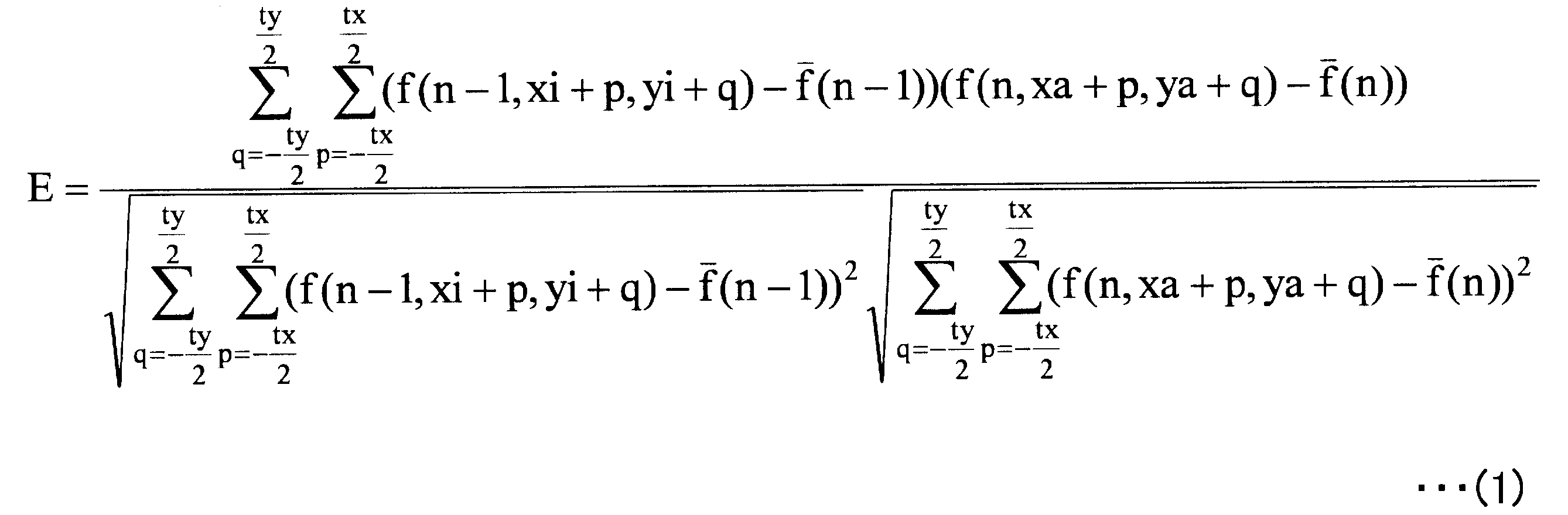
より具体的には、動きベクトル算出部752は、テンプレート領域とマッチング領域のG成分の分散値を用いてマッチングを行い、次式(1)に従って正規化相互相関値Eを算出する。f(n,x,y)は画像番号nの画像データである。
以上のようにし、図5に示すように、動きベクトル算出部752は各ブロック120それぞれについてマッチングを行い、マッチング領域121を検出する。
そして、動きベクトル算出部752は、画像I(n-1)の各ブロック110のテンプレート領域111と、画像I(n)の対応するブロック120内のマッチング領域121との間で、中心座標(xi,yi),(xa,ya)の変化を動きベクトルとして算出する。得られたマッチング結果のデータは、記憶部740に保持される。具体的には、各テンプレート領域番号と対応付けて、得られたマッチング領域の中心座標やその正規化相互相関値E、動きベクトル等が記憶される。
動きベクトルを算出したならば、図3に示すように、続いて動きパターン分類部754が、動きパターン分類処理を実行して画像I(n)の動きパターンを分類する(ステップa9)。この画像I(n)の動きパターンの分類は、画像I(n-1),I(n)間の動きベクトルをもとに動きパターンを「平行移動上」「平行移動左上」「平行移動左」「平行移動左下」「平行移動下」「平行移動右下」「平行移動右」「平行移動右上」「前進移動」「後進移動」「左回転移動」「右回転移動」「その他」のいずれかに分類することによって行う。図7は、動きパターン分類処理の詳細な処理手順を示すフローチャートである。
すなわち先ず、動きパターン分類部754は、図3のステップa7で行ったマッチングの結果得られた正規化相互相関値Eを画像I(n-1),I(n)間の動きベクトルの信頼度とし、信頼度の低い動きベクトルについてはマッチング失敗として、動きパターンの分類に用いる動きベクトルから除外する処理を行う(ステップa911)。続いて、動きパターン分類部754は、動きパターンの分類を行うか否かを判定する。例えば、動きパターン分類部754は、信頼度の低い動きベクトルを除外した結果、動きパターンの分類に使用可能な動きベクトル数が動きベクトルの総数の半数以下(実施の形態1では8個以下)の場合には、動きパターンの分類を行わないと判定し(ステップa913:No)、ステップa927に移行して画像I(n)の動きパターンを「その他」に分類する。これは、マッチング失敗数が多く、動きパターンの分類を行っても結果に信頼性が得られないと考えられるためである。
図8は、画像I(n)の一例を示す図であり、図8中において、画像I(n-1)との間で設定された動きパターンの分類に使用可能な動きベクトル131を示している。例えば、時系列の前後でカプセル型内視鏡10の撮像位置が大きく変わり、画像の見え方が大きく変わると、マッチングの結果得られた正規化相互相関値Eが低くなる。このため、図8に示す画像I(n)のように、動きベクトルの信頼度が低いと判定される箇所133が多く発生する。このような場合には、動きパターンは、「その他」に分類される。なお、動きパターンの分類に使用可能な動きベクトルが半数以下の場合に動きパターンを「その他」に分類することとしたが、半数以下である必要はなく、閾値は適宜設定してよい。
一方、動きパターンの分類を行う場合には(ステップa913:Yes)、動きパターン分類部754は、画像I(n)の動きパターンを「平行移動」に分類する処理(平行移動分類処理)を行う(ステップa915)。動きパターンが「平行移動」の場合、画像I(n-1),I(n)間の動きベクトルは全て同じような向きを持つ。このため、動きパターン分類部754は、各動きベクトルの向きが略同一の方向を向いている場合には、画像I(n)の動きパターンを「平行移動」に分類する。具体的には、動きパターン分類部754は、各動きベクトルの向きの分散を求め、得られた分散の値が所定の閾値よりも小さければ動きパターンを「平行移動」に分類する。
図9は、画像I(n)の一例を示す図であり、図9中において、画像I(n-1)との間で設定された動きパターンの分類に使用可能な動きベクトル141を示している。図9に示す画像I(n)のように、各動きベクトル141がほぼ同一方向を向いている場合、動きパターンは「平行移動」に分類される。動きパターンを「平行移動」に分類した場合には、動きパターン分類部754は、続いて、各動きベクトルの向きの平均を求め、「上」「左上」「左」「左下」「下」「右下」「右」「右上」のいずれかに分類する。これによって、「平行移動」に分類された画像I(n)の動きパターンが、さらにそれぞれ移動方向が異なる「平行移動上」「平行移動左上」「平行移動左」「平行移動左下」「平行移動下」「平行移動右下」「平行移動右」「平行移動右上」のいずれかに分類される。
続いて、図7に示すように、画像I(n)の動きパターンが「平行移動」に分類されたか否かを判定し、分類された場合には(ステップa917:Yes)、本処理を終了して図3のステップa9にリターンする。一方、分類されない場合には(ステップa917:No)、動きパターン分類部754は、画像I(n)の動きパターンを「前進移動」または「後進移動」に分類する処理(前進/後進移動分類処理)を行う(ステップa919)。
図10は、画像I(n)の一例を示す図であり、図10中において、画像I(n-1)との間で設定された動きパターンの分類に使用可能な動きベクトル151を示している。「前進移動」または「後進移動」の分類では、動きパターン分類部754は、図10中に破線で示すように、各動きベクトル151に沿った直線153をそれぞれ設定し、設定した直線153同士が交わる位置に投票点155を設定する。そして、動きパターン分類部754は、設定した投票点155が例えば予め設定される所定サイズの座標範囲内に集中している場合に、動きパターンを「前進移動」または「後進移動」に分類する。例えば、画像I(n)上を走査して所定の基準投票点数以上の投票点が含まれる座標範囲157を探索し、探索された場合に「前進移動」または「後進移動」に分類する。基準投票点数としては、例えば投票点の総数の半数以上等、適宜設定することができる。
そして、「前進移動」または「後進移動」に分類した場合には、動きパターン分類部754は、探索された座標範囲内の各投票点の例えば平均位置に対して、各動きベクトルの向きが平均位置の方向を向いていれば「前進移動」とし、反対の方向を向いていれば「後進移動」とする。例えば、図10の例では、各動きベクトル151は、投票点155が集中する座標範囲157と反対の方向を向いており、「後進移動」に分類される。なお、実際にはカプセル型内視鏡10の位置は移動していないが、消化管の粘膜が蠕動運動によって収縮し、カプセル型内視鏡10が前進または後進したような画像が得られた場合にも、「前進移動」または「後進移動」に分類される。
続いて、図7に示すように、画像I(n)の動きパターンが「前進移動」または「後進移動」に分類されたか否かを判定し、分類された場合には(ステップa921:Yes)、本処理を終了して図3のステップa9にリターンする。一方、分類されない場合には(ステップa921:No)、動きパターン分類部754は、画像I(n)の動きパターンを「回転移動」に分類する処理(回転移動分類処理)を行う(ステップa923)。
図11は、画像I(n)の一例を示す図であり、図11中において、画像I(n-1)との間で設定された動きパターンの分類に使用可能な動きベクトル161を示している。「回転移動」の分類では、動きパターン分類部754は、図11中に破線で示すように、各動きベクトル161に対して直交する直線163をそれぞれ設定し、設定した直線163同士が交わる位置に投票点165を設定する。そして、動きパターン分類部754は、設定した投票点165が例えば予め設定される所定サイズの座標範囲内に集中している場合に、動きパターンを「回転移動」に分類する。例えば、画像I(n)上を走査して所定の基準投票点数以上の投票点が含まれる座標範囲167を探索し、探索された場合に「回転移動」に分類する。基準投票点数としては、例えば投票点の総数の半数以上等、適宜設定することができる。
そして、「回転移動」に分類した場合には、動きパターン分類部754は、続いて、探索された座標範囲内の各投票点の例えば平均位置を回転中心位置とする。そして、動きパターン分類部754は、各動きベクトルそれぞれについて、その始点および終点をそれぞれ回転中心位置と結んだ各直線のなす角度を算出し、求めた角度が正の値か負の値かによって回転方向を「左」「右」のいずれかに分類する。図12,図13は、回転方向の判定方法を説明する図である。図12に示すように、回転中心位置171を動きベクトル173の始点175と結んだ直線と、回転中心位置171を動きベクトル173の終点177と結んだ直線とのなす角度θが正の値の場合には、回転方向を「左」とする。一方、図13に示すように、回転中心位置181を動きベクトル183の始点185と結んだ直線と、回転中心位置181を動きベクトル183の終点187と結んだ直線とのなす角度θが負の値の場合には、回転方向を「右」とする。これによって、「回転移動」に分類された画像I(n)の動きパターンが、さらにそれぞれ回転方向が異なる「左回転移動」「右回転移動」のいずれかに分類される。
続いて、図7に示すように、画像I(n)の動きパターンが「回転移動」に分類されたか否かを判定し、分類された場合には(ステップa925:Yes)、本処理を終了して図3のステップa9にリターンする。一方、分類されない場合には(ステップa925:No)、動きパターン分類部754は、ステップa927に移行して、画像I(n)の動きパターンを「その他」に分類する。すなわち、動きパターン分類部754は、画像I(n)中の各動きベクトルの向きに規則性がなく、画像I(n-1),I(n)間の動きパターンが「平行移動」「前進移動」「後進移動」「回転移動」のいずれにも分類されない場合に、ステップa927において画像I(n)の動きパターンを「その他」に分類し、図3のステップa9にリターンする。この動きパターン分類処理によって分類された画像I(n)の動きパターンは、記憶部740に保持される。
図3に示すように、動きパターン分類処理を実行したならば、演算部750が画像番号nをインクリメントしてn=n+1とし(ステップa11)、nの値が時系列画像を構成する画像総数Nと一致するか否かによって、次に処理対象とする画像の有無を判定する。n=Nでないならば(ステップa13:No)、ステップa3に戻る。一方、n=Nの場合には(ステップa13:Yes)、演算部750は、画像番号nを再度初期化する(ステップa15)。そして、動き方向変化判定部755が、画像I(n-1),I(n)の動きパターンを記憶部740から読み出して取得する。そして、動き方向変化判定部755は、取得した動きパターンを比較し、動き方向の変化を判定する(ステップa17)。動き方向が変化しない場合には(ステップa19:No)、ステップa23に移行する。
一方、動き方向が変化した場合には(ステップa19:Yes)、動き方向変化画像抽出部751が、画像I(n)を動き方向変化画像として抽出し(ステップa21)、ステップa23に移行する。具体的には、動き方向変化判定部755は、画像I(n-1),I(n)の動きパターンが異なる場合に、その類似度を判定する。そして、動き方向変化判定部755は、動きパターンが類似している場合には動き方向は変化していないと判定し、動きパターンが非類似の場合に動き方向が変化したと判定する。例えば、「平行移動上」と「平行移動左上」、「平行移動左上」と「平行移動左」、「平行移動左」と「平行移動左下」、「平行移動左下」と「平行移動下」、「平行移動下」と「平行移動右下」、「平行移動右下」と「平行移動右」、「平行移動右」と「平行移動右上」、「平行移動右上」と「平行移動上」をそれぞれ類似する類似動きパターンとして予め定義しておき、画像I(n-1),I(n)の動きパターンの組み合わせがいずれかの類似動きパターンと合致する場合には、動き方向は変化していないと判定する。抽出した動き方向変化画像のデータ(画像番号)は、記憶部740に保持される。
そして、ステップa23では、演算部750が画像番号nをインクリメントしてn=n+1とし、続いてnの値が時系列画像を構成する画像総数Nと一致するか否かによって、次に処理対象とする画像の有無を判定する。n=Nでないならば(ステップa25:No)、ステップa17に戻る。一方、n=Nの場合には(ステップa25:Yes)、続いて画像表示制御部761が時系列画像を構成する各画像を時系列順に順次表示する制御を行うが、このとき、表示速度制御部763が、ステップa21で抽出された動き方向変化画像を中心にして前後に連続する所定数の画像を近傍画像とし、動き方向変化画像および近傍画像の表示速度を、その他の画像の表示速度に比べて相対的に低くする制御を行う(ステップa27)。
以上説明したように、実施の形態1によれば、時系列画像を構成する画像間の動きベクトルをもとに各画像の動きパターンを分類し、この動きパターンをもとに動き方向が変化した画像を抽出することができる。そして、時系列画像を順次表示する際に、動き方向が変化した画像およびその近傍画像の表示速度を、その他の画像の表示速度に比べて相対的に低くする制御を行うことができるので、時系列画像を観察する際、観察者は、動き方向が変化する画像を他と比べて遅い表示速度で観察することができる。また、観察者としては、観察時に表示速度が遅くなった場合に、画像の動き方向が変化すると予測できるという効果もある。これによれば、観察者による表示内容の見逃しが発生する事態を防止できる。したがって、時系列画像の内容を効率良く把握することができ、観察効率が向上するという効果を奏することができる。
なお、実施の形態1では、動き方向が変化した画像を動き方向変化画像として抽出する場合について説明したが、同じ動きパターンの画像が所定数続いた後、画像の動き方向が変化した場合に、この動き方向が変化した画像を動き方向変化画像として抽出することとしてもよい。図14は、本変形例における画像処理装置の処理手順を示すフローチャートである。なお、実施の形態1において図3に示して説明した処理工程と同一の処理工程については、同一の符号を付している。
図14に示すように、本変形例の画像処理装置では、動き方向変化判定部が、ステップa17において画像I(n-1),I(n)の動きパターンを比較して動き方向の変化を判定した結果、動き方向が変化した場合に(ステップa19:Yes)、続いて画像I(n-1)から遡って、画像I(n-1)と同じ動きパターンの画像が所定数続いているか否かを判定する(ステップb20)。ここで、所定数としては、2以上の値が予め設定され、固定値としてもよいし、ユーザ操作等によって設定変更可能に構成してもよい。そして、続いていない場合には(ステップb20:No)、ステップa23に移行する。一方、続いている場合には(ステップb20:Yes)、ステップa21に移行して動き方向変化画像抽出部が画像I(n)を動き方向変化画像として抽出した後、ステップa23に移行する。
図15は、本変形例における動き方向変化画像の抽出処理について説明する図であり、図15中の奥側から手前側に向けて連続する時系列画像を示している。図15に示すように、動きパターンが「前進移動」である所定数以上の画像が画像I(n-1)まで続いた後、画像I(n)で動きパターンが「平行移動右」に変化した場合に、画像I(n)が動き方向変化画像として抽出される。そしてこの場合、画像I(n)および前後に連続する所定数の画像の表示速度が減速される。本変形例によれば、同じ動きパターンの画像が続いた後で動き方向が変化した場合に、この変化した画像を他と比べて遅い表示速度で観察することができる。したがって、画像の動き方向の急激な変化に対する認識の遅れや、認識の遅れに伴って重要な情報を見逃してしまうといった事態を防止することができる。
(実施の形態2)
次に、実施の形態2について説明する。図16は、実施の形態2における画像処理装置70bの機能構成を説明するブロック図である。なお、実施の形態1で説明した構成と同一の構成については、同一の符号を付する。実施の形態2では、画像処理装置70bは、外部インターフェース710と、入力部720と、表示部730と、記憶部740bと、演算部750bと、画像処理装置70b全体の動作を制御する制御部760とを備える。記憶部740bには、画像処理プログラム741bが格納される。
次に、実施の形態2について説明する。図16は、実施の形態2における画像処理装置70bの機能構成を説明するブロック図である。なお、実施の形態1で説明した構成と同一の構成については、同一の符号を付する。実施の形態2では、画像処理装置70bは、外部インターフェース710と、入力部720と、表示部730と、記憶部740bと、演算部750bと、画像処理装置70b全体の動作を制御する制御部760とを備える。記憶部740bには、画像処理プログラム741bが格納される。
また、演算部750bは、動き方向変化画像抽出部751bを含み、動き方向変化画像抽出部751bは、ブロック分割部753を有する動きベクトル算出部752と、動きパターン分類部754と、グループ化手段としてのグループ化部756と、グループ判定手段としてのグループ判定部757と、動き方向変化判定部758とで構成される。グループ化部756は、動きパターンが同じと判定された時系列で連続する画像群をグループ化する。グループ判定部757は、グループ化された隣接するグループが、所定の基準画像数以上の画像で構成されるグループか否かを判定する。本実施の形態では、基準画像数として、隣接する時系列で前のグループに適用する基準前画像数と、後ろのグループに適用する基準後画像数とが予め設定されている。動き方向変化判定部758は、グループ間の動き方向の変化を判定する。そして、動き方向変化画像抽出部751bは、動き方向変化判定部758によって動き方向が変化したと判定されたグループ内において時系列で先頭の画像を動き方向変化画像として抽出する。
図17は、実施の形態2における画像処理装置70bが行う処理手順を示すフローチャートである。なお、ここで説明する処理は、記憶部740bに格納された画像処理プログラム741bに従って画像処理装置70bの各部が動作することによって実現される。また、実施の形態1において図3に示して説明した処理工程と同一の処理工程については、同一の符号を付している。
図17に示すように、実施の形態2の画像処理装置70bでは、ステップa13においてn=Nと判定した場合に(ステップa13:Yes)、続いてグループ化部756がグループ化処理を実行する(ステップc15)。図18は、グループ化処理を説明する図であり、図18中の最も奥側を先頭(画像番号1)の画像I(1)とし、手前側に向けて連続する時系列画像を示している。グループ化処理では、動きパターンが同じと判定された時系列で連続する画像群をグループ化する。図18の例では、動きパターンが「平行移動右」に分類された画像I(1)~I(4)の画像群がグループG(1)としてグループ化されている。そして、グループG(1)の次に画像パターンが「平行移動左上」に分類された4枚の画像がグループG(2)としてグループ化され、グループG(2)の次に画像パターンが「平行移動右」に分類された3枚の画像がグループG(3)としてグループ化され、グループG(3)の次に画像パターンが「右回転移動」に分類されてグループG(4)としてグループ化された画像が続いている。
図19は、グループ化処理の詳細な処理手順を示すフローチャートである。グループ化処理では、グループ化部756は、先ず画像番号nを再度初期化し(ステップd1)、画像I(n-1)を先頭のグループに登録する(ステップd3)。続いて、グループ化部756は、図17のステップa9で分類された画像I(n-1),I(n)の動きパターンを記憶部740bから読み出して取得する(ステップd5)。そして、グループ化部756は、取得した動きパターンを比較し、動きパターンが同一の場合には(ステップd7:Yes)、画像I(n-1)が登録されたグループに画像I(n)を追加登録する(ステップd9)。一方、動きパターンが異なる場合には(ステップd7:No)、グループ化部756は、新たにグループを作成して画像I(n)を登録する(ステップd11)。そして、グループ化部756は、画像番号nをインクリメントしてn=n+1とし(ステップd13)、nの値が時系列画像を構成する画像総数Nと一致するか否かによって、次に処理対象とする画像の有無を判定する。n=Nでないならば(ステップd15:No)、ステップd5に戻る。一方、n=Nの場合には(ステップd15:Yes)、先頭のグループから順に各グループに通し番号を付与し(ステップd17)、図17のステップc15にリターンする。グループ化された各グループのデータ(グループ情報)は、記憶部740bに保持される。具体的には、各グループに付与された通し番号と対応付けて、グループ内の最後尾の画像番号や、その動きパターン(グループを構成する画像の動きパターン)等が記憶される。
そして、図17に示すように、グループ化処理を実行したならば、続いてグループ判定部757が、処理対象のグループを識別するためのグループ番号mを初期化する(ステップc17)。そして、グループ判定部757は、グループG(m-1),G(m)のグループ情報を記憶部740bから読み出して取得する(ステップc19)。
続いて、グループ判定部757は、グループG(m-1)を構成する画像数が基準前画像数以上か否かを判定する。グループG(m-1)を構成する画像数は、例えばグループG(m-1)内の最後尾の画像番号からグループG(m-2)内の最後尾の画像番号を差し引くことによって求まる。そして、基準前画像数以上の場合には(ステップc21:Yes)、グループ判定部757は、続いてグループG(m)を構成する画像数が基準後画像数以上か否かを判定する。グループG(m)を構成する画像数は、例えばグループG(m)内の最後尾の画像番号からグループG(m-1)内の最後尾の画像番号を差し引くことによって求まる。ここで、基準前画像数および基準後画像数には、それぞれ1以上の値が予め設定される。基準前画像数および基準後画像数の各値は、固定値としてもよいし、ユーザ操作等によって設定変更可能に構成してもよい。
そして、基準後画像数以上の場合には(ステップc23:Yes)、グループ判定部757は、グループG(m-1),G(m)の動きパターンを比較し、動き方向の変化を判定する(ステップc24)。そして、図17に示すように、動き方向が変化しない場合には(ステップc25:No)、ステップc27に移行する。なお、このとき、グループG(m-1),G(m)の動きパターンが「その他」の場合に、後段のステップc26の処理を行わずにステップc27に移行することとしてもよい。一方、動き方向が変化した場合には(ステップc25:Yes)、動き方向変化画像抽出部751bが、グループG(m)内の時系列で先頭の画像を動き方向変化画像として抽出し(ステップc26)、ステップc27に移行する。
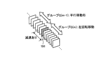
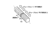
図20~図22は、動き方向の変化の判定方法を説明する図である。本判定方法では、動きパターンのうち、「平行移動」「回転移動」「前進移動」「後進移動」「その他」を親パターンとする。そして、「平行移動上」「平行移動左上」「平行移動左」「平行移動左下」「平行移動下」「平行移動右下」「平行移動右」「平行移動右上」を親パターン「平行移動」に対する子パターンとする。また、「左回転移動」「右回転移動」を親パターン「回転移動」に対する子パターンとする。例えば、図20に示すように、グループG(m-1),G(m)の動きパターンの親パターンが「平行移動」と「回転移動」とで異なる場合には、動き方向が変化したと判定する。したがって、時系列画像の表示の際には、グループG(m)内の時系列で先頭の画像191および前後に連続する所定数の画像の表示速度が減速される。一方、グループG(m-1),G(m)の動きパターンの親パターンが「平行移動」であり、動きパターンの変化が移動方向の変化である場合には、子パターンの移動方向が類似するか否かを判定する。
例えば、予め「上」と「左上」、「左上」と「左」、「左」と「左下」、「左下」と「下」、「下」と「右下」、「右下」と「右」、「右」と「右上」、「右上」と「上」を類似する移動方向として定義しておく。そして、図21に示すように、グループG(m-1),G(m)の動きパターンの子パターンが「平行移動右」と「平行移動左上」であり、移動方向が非類似の場合には、動き方向が変化したと判定する。したがって、時系列画像の表示の際には、グループG(m)内の時系列で先頭の画像193および前後に連続する所定数の画像の表示速度が減速される。これに対し、図22に示すように、グループG(m-1),G(m)の動きパターンの子パターンが「平行移動右」と「平行移動右上」であり、移動方向が類似する場合には、動き方向が変化しないと判定する。したがって、時系列画像の表示の際には、グループG(m)内の時系列で先頭の画像195および前後に連続する所定数の画像の表示速度は減速されない。
そして、グループ判定部757は、グループ番号mをインクリメントしてm=m+1とし(ステップc27)、mの値がグループ総数Mと一致するか否かによって、次に処理対象とするグループの有無を判定する。m=Mでないならば(ステップc29:No)、ステップc19に戻る。一方、m=Mの場合には(ステップc29:Yes)、続いてステップa27に移行し、画像表示制御部761が時系列画像を構成する各画像を時系列順に順次表示する制御を行うが、このとき、表示速度制御部763が、ステップc26で抽出された動き方向変化画像およびこの動き方向変化画像と前後に連続する所定数の画像の表示速度を、その他の画像の表示速度に比べて相対的に低くする制御を行う。
以上説明したように、実施の形態2によれば、実施の形態1と同様の効果を奏することができる。また、時系列画像を構成する各画像のうち、動きパターンが同じと判定された時系列で連続する画像群をグループ化し、グループ単位で動き方向の変化を判定することができる。そして、動き方向の変化だけでなく、動きパターンの変化の前後で同じ動きパターンが所定数連続しているかどうかを条件として、動き方向変化画像を抽出することができる。
なお、上記の実施形態では、カプセル型内視鏡10により撮像された被検体1内部の画像を表示する場合について説明したが、これに限定されるものではなく、複数の画像で構成される時系列画像を順次表示させる場合であれば同様に適用することができる。
以上のように、本発明の画像処理装置および画像処理プログラムは、時系列画像を表示する場合の観察者による表示内容の見逃しの防止し、観察を効率よく行うのに有用である。
Claims (13)
- 時系列画像を順次表示する画像処理装置において、
前記時系列画像を構成する画像間の動きを検出し、該検出した画像間の動きをもとに動き方向が変化する画像を抽出する動き方向変化画像抽出手段と、
前記動き方向変化画像抽出手段によって抽出された画像および該画像の近傍画像の表示速度を、他の画像の表示速度に比べて相対的に低く制御する表示速度制御手段と、
を備えることを特徴とする画像処理装置。 - 前記表示速度制御手段は、前記近傍画像として、前記動き方向変化画像抽出手段によって抽出された画像を中心にして前後に連続する所定数の画像の表示速度を他の画像の表示速度に比べて相対的に低くすることを特徴とする請求項1に記載の画像処理装置。
- 前記動き方向変化画像抽出手段は、前記時系列画像を構成する画像間の動きベクトルに基づいて前記動き方向が変化する画像を抽出することを特徴とする請求項1または2に記載の画像処理装置。
- 前記画像を複数のブロックに分割するブロック分割手段と、
前記ブロック分割手段によって分割されたブロック毎に前記動きベクトルを算出する動きベクトル算出手段と、
を備えることを特徴とする請求項3に記載の画像処理装置。 - 前記動き方向変化画像抽出手段は、前記動きベクトル算出手段によって算出された動きベクトルをもとに動きパターンを判定する動きパターン判定手段を有し、前記動きパターン判定手段によって判定された動きパターンをもとに前記動き方向が変化する画像を抽出することを特徴とする請求項4に記載の画像処理装置。
- 前記動きパターン判定手段は、前記動きベクトル算出手段によって算出された動きベクトルの向きに従って前記動きパターンを判定することを特徴とする請求項5に記載の画像処理装置。
- 前記動きパターン判定手段は、前記動きパターンを、移動方向別の平行移動、回転移動、前進移動、後進移動およびその他のいずれかに分類し、
前記動き方向変化画像抽出手段は、前記動きパターン判定手段によって分類された動きパターンが変化した画像を抽出することを特徴とする請求項5または6に記載の画像処理装置。 - 前記動き方向変化画像抽出手段は、前記動きパターンの変化が平行移動の移動方向の変化の場合であって、該変化した移動方向が類似する場合には、前記動きパターンが変化した画像を抽出しないことを特徴とする請求項7に記載の画像処理装置。
- 前記動き方向変化画像抽出手段は、前記時系列画像において、同じ動きパターンの画像が所定数続いた後、画像の動きパターンが変化した場合に、該動きパターンが変化した画像を抽出することを特徴とする請求項5~8のいずれか1つに記載の画像処理装置。
- 前記動き方向変化画像抽出手段は、前記時系列画像において、一の動きパターンの画像が所定数続いた後、前記一の動きパターンとは別の他の動きパターンの画像が所定数続いた場合に、動きパターンが前記他の動きパターンへと変化した画像を抽出することを特徴とする請求項5~8のいずれか1つに記載の画像処理装置。
- 前記動き方向変化画像抽出手段は、
動きパターンが同じと判定された時系列で連続する画像群をグループ化するグループ化手段と、
前記グループ化手段によってグループ化された隣接するグループが、それぞれ予め設定される基準画像数以上の画像で構成されるグループか否かを判定するグループ判定手段と、
を有し、
前記グループ判定手段によって前記基準画像数以上の画像で構成されると判定された隣接する各グループの動きパターンをもとに、動き方向が変化したグループ内において時系列で先頭の画像を抽出することを特徴とする請求項5~8のいずれか1つに記載の画像処理装置。 - 前記基準画像数として、時系列で前のグループに適用する基準前画像数と、時系列で後のグループに適用する基準後画像数とが予め設定されており、
前記グループ判定手段は、前記隣接するグループのうち、時系列で前のグループについて前記基準前画像数以上の画像で構成されるグループか否かを判定し、時系列で後のグループについて前記基準後画像数以上の画像で構成されるグループか否かを判定することを特徴とする請求項11に記載の画像処理装置。 - 時系列画像を順次表示する表示部を備えたコンピュータに、
前記時系列画像を構成する画像間の動きを検出し、該検出した画像間の動きをもとに動き方向が変化する画像を抽出する動き方向変化画像抽出ステップと、
前記動き方向変化画像抽出ステップによって抽出された画像および該画像の近傍画像の表示速度を、他の画像の表示速度に比べて相対的に低く制御する表示速度制御ステップと、
を実行させることを特徴とする画像処理プログラム。
Priority Applications (3)
| Application Number | Priority Date | Filing Date | Title |
|---|---|---|---|
| EP08872675.7A EP2248457B1 (en) | 2008-02-19 | 2008-11-19 | Image processing device and image processing program |
| CN2008801269338A CN101945610B (zh) | 2008-02-19 | 2008-11-19 | 图像处理装置 |
| US12/857,892 US9031387B2 (en) | 2008-02-19 | 2010-08-17 | Image processing apparatus |
Applications Claiming Priority (2)
| Application Number | Priority Date | Filing Date | Title |
|---|---|---|---|
| JP2008-038018 | 2008-02-19 | ||
| JP2008038018A JP5085370B2 (ja) | 2008-02-19 | 2008-02-19 | 画像処理装置および画像処理プログラム |
Related Child Applications (1)
| Application Number | Title | Priority Date | Filing Date |
|---|---|---|---|
| US12/857,892 Continuation US9031387B2 (en) | 2008-02-19 | 2010-08-17 | Image processing apparatus |
Publications (1)
| Publication Number | Publication Date |
|---|---|
| WO2009104316A1 true WO2009104316A1 (ja) | 2009-08-27 |
Family
ID=40985209
Family Applications (1)
| Application Number | Title | Priority Date | Filing Date |
|---|---|---|---|
| PCT/JP2008/071049 Ceased WO2009104316A1 (ja) | 2008-02-19 | 2008-11-19 | 画像処理装置および画像処理プログラム |
Country Status (5)
| Country | Link |
|---|---|
| US (1) | US9031387B2 (ja) |
| EP (1) | EP2248457B1 (ja) |
| JP (1) | JP5085370B2 (ja) |
| CN (1) | CN101945610B (ja) |
| WO (1) | WO2009104316A1 (ja) |
Families Citing this family (10)
| Publication number | Priority date | Publication date | Assignee | Title |
|---|---|---|---|---|
| JP4956694B2 (ja) | 2010-09-29 | 2012-06-20 | オリンパスメディカルシステムズ株式会社 | 情報処理装置及びカプセル型内視鏡システム |
| JP2013099464A (ja) * | 2011-11-09 | 2013-05-23 | Fujifilm Corp | 内視鏡システム、内視鏡システムのプロセッサ装置、及び画像表示方法 |
| JP5886075B2 (ja) * | 2012-02-21 | 2016-03-16 | 日本放送協会 | 画像処理装置及びプログラム |
| JP5941758B2 (ja) * | 2012-06-06 | 2016-06-29 | オリンパス株式会社 | 内視鏡装置 |
| EP3045100A1 (en) * | 2013-09-09 | 2016-07-20 | Olympus Corporation | Image display device, image display method, and image display program |
| JP6249867B2 (ja) | 2014-04-18 | 2017-12-20 | オリンパス株式会社 | カプセル内視鏡システム、カプセル内視鏡、受信装置、カプセル内視鏡の撮像制御方法、及びプログラム |
| JP6458357B2 (ja) * | 2014-05-26 | 2019-01-30 | 株式会社リコー | 検査装置、検査方法及び検査プログラム |
| JP6333494B1 (ja) * | 2016-08-02 | 2018-05-30 | オリンパス株式会社 | 画像処理装置、カプセル型内視鏡システム、画像処理装置の作動方法、及び画像処理装置の作動プログラム |
| JP2019201757A (ja) * | 2018-05-22 | 2019-11-28 | オリンパス株式会社 | カプセル型内視鏡、カプセル型内視鏡システム及びカプセル型内視鏡の送信方法 |
| CN112584738B (zh) * | 2018-08-30 | 2024-04-23 | 奥林巴斯株式会社 | 记录装置、图像观察装置、观察系统、观察系统的控制方法及存储介质 |
Citations (2)
| Publication number | Priority date | Publication date | Assignee | Title |
|---|---|---|---|---|
| WO2006100808A1 (ja) * | 2005-03-22 | 2006-09-28 | Osaka University | カプセル内視鏡画像表示制御装置 |
| JP2006280792A (ja) | 2005-04-04 | 2006-10-19 | Olympus Corp | 画像表示装置 |
Family Cites Families (7)
| Publication number | Priority date | Publication date | Assignee | Title |
|---|---|---|---|---|
| JP3319678B2 (ja) * | 1995-08-11 | 2002-09-03 | ケイディーディーアイ株式会社 | 動画像の高速ブラウジング装置 |
| JP2001245303A (ja) * | 2000-02-29 | 2001-09-07 | Toshiba Corp | 動画像符号化装置および動画像符号化方法 |
| US6709387B1 (en) * | 2000-05-15 | 2004-03-23 | Given Imaging Ltd. | System and method for controlling in vivo camera capture and display rate |
| JP4418400B2 (ja) * | 2005-05-20 | 2010-02-17 | オリンパスメディカルシステムズ株式会社 | 画像表示装置 |
| US20070060798A1 (en) * | 2005-09-15 | 2007-03-15 | Hagai Krupnik | System and method for presentation of data streams |
| JP4768451B2 (ja) * | 2006-01-18 | 2011-09-07 | 株式会社リコー | 画像処理装置、画像形成装置、プログラムおよび画像処理方法 |
| CN1836624A (zh) * | 2006-03-07 | 2006-09-27 | 上海大学 | 智能内窥镜视觉导航系统及方法 |
-
2008
- 2008-02-19 JP JP2008038018A patent/JP5085370B2/ja not_active Expired - Fee Related
- 2008-11-19 CN CN2008801269338A patent/CN101945610B/zh not_active Expired - Fee Related
- 2008-11-19 WO PCT/JP2008/071049 patent/WO2009104316A1/ja not_active Ceased
- 2008-11-19 EP EP08872675.7A patent/EP2248457B1/en not_active Not-in-force
-
2010
- 2010-08-17 US US12/857,892 patent/US9031387B2/en active Active
Patent Citations (2)
| Publication number | Priority date | Publication date | Assignee | Title |
|---|---|---|---|---|
| WO2006100808A1 (ja) * | 2005-03-22 | 2006-09-28 | Osaka University | カプセル内視鏡画像表示制御装置 |
| JP2006280792A (ja) | 2005-04-04 | 2006-10-19 | Olympus Corp | 画像表示装置 |
Non-Patent Citations (1)
| Title |
|---|
| See also references of EP2248457A4 |
Also Published As
| Publication number | Publication date |
|---|---|
| US9031387B2 (en) | 2015-05-12 |
| EP2248457A4 (en) | 2012-05-02 |
| EP2248457A1 (en) | 2010-11-10 |
| CN101945610A (zh) | 2011-01-12 |
| EP2248457B1 (en) | 2016-05-04 |
| US20100310239A1 (en) | 2010-12-09 |
| JP5085370B2 (ja) | 2012-11-28 |
| JP2009195343A (ja) | 2009-09-03 |
| CN101945610B (zh) | 2012-09-26 |
Similar Documents
| Publication | Publication Date | Title |
|---|---|---|
| JP5085370B2 (ja) | 画像処理装置および画像処理プログラム | |
| US8830307B2 (en) | Image display apparatus | |
| US12193634B2 (en) | Method for real-time detection of objects, structures or patterns in a video, an associated system and an associated computer readable medium | |
| EP1769729B1 (en) | System and method for in-vivo feature detection | |
| US8837821B2 (en) | Image processing apparatus, image processing method, and computer readable recording medium | |
| US8478010B2 (en) | Image processing apparatus, image processing program recording medium, and image processing method | |
| JP5972865B2 (ja) | 生体内画像の部分を表示するシステム及びその作動方法 | |
| JP4959445B2 (ja) | 画像処理装置および画像処理プログラム | |
| US10178941B2 (en) | Image processing apparatus, image processing method, and computer-readable recording device | |
| JP6411834B2 (ja) | 画像表示装置、画像表示方法、及び画像表示プログラム | |
| JP2010158308A (ja) | 画像処理装置、画像処理方法および画像処理プログラム | |
| US20150187063A1 (en) | Medical device and method for operating the same | |
| US20170079506A1 (en) | Image processing device, image processing method, and computer-readable recording medium | |
| US20240257348A1 (en) | Endoscopic image processing device, endoscopic image processing method, and endoscope system | |
| US20100034436A1 (en) | Image processing apparatus, computer program product and image processing method | |
| JP5004736B2 (ja) | 画像処理装置および画像処理プログラム | |
| US8406489B2 (en) | Image display apparatus | |
| JP2010142375A (ja) | 画像処理装置、画像処理プログラムおよび画像処理方法 | |
| KR20140021193A (ko) | 피부 진단기기 및 이의 제어방법 | |
| JP2006304993A (ja) | 画像処理装置、画像処理方法、及び画像処理プログラム | |
| EP4726666A1 (en) | Apparatus and method | |
| JPWO2016056408A1 (ja) | 画像処理装置、画像処理方法、及び画像処理プログラム | |
| CN120036703A (zh) | 一种内窥镜辅助诊断设备及其诊断提示方法 | |
| Isa et al. | Development of an AI-Driven System for Early Bowel Cancer Detection using Capsule Endoscopy Imaging | |
| US20230122280A1 (en) | Systems and methods for providing visual indicators during colonoscopy |
Legal Events
| Date | Code | Title | Description |
|---|---|---|---|
| WWE | Wipo information: entry into national phase |
Ref document number: 200880126933.8 Country of ref document: CN |
|
| 121 | Ep: the epo has been informed by wipo that ep was designated in this application |
Ref document number: 08872675 Country of ref document: EP Kind code of ref document: A1 |
|
| WWE | Wipo information: entry into national phase |
Ref document number: 2008872675 Country of ref document: EP |
|
| NENP | Non-entry into the national phase |
Ref country code: DE |