WO2009104764A1 - 通信装置、通信システム、受信方法およびプログラム - Google Patents
通信装置、通信システム、受信方法およびプログラム Download PDFInfo
- Publication number
- WO2009104764A1 WO2009104764A1 PCT/JP2009/053088 JP2009053088W WO2009104764A1 WO 2009104764 A1 WO2009104764 A1 WO 2009104764A1 JP 2009053088 W JP2009053088 W JP 2009053088W WO 2009104764 A1 WO2009104764 A1 WO 2009104764A1
- Authority
- WO
- WIPO (PCT)
- Prior art keywords
- signal
- unit
- packet
- received
- retransmission
- Prior art date
- Legal status (The legal status is an assumption and is not a legal conclusion. Google has not performed a legal analysis and makes no representation as to the accuracy of the status listed.)
- Ceased
Links
Images


Classifications
-
- H—ELECTRICITY
- H04—ELECTRIC COMMUNICATION TECHNIQUE
- H04L—TRANSMISSION OF DIGITAL INFORMATION, e.g. TELEGRAPHIC COMMUNICATION
- H04L1/00—Arrangements for detecting or preventing errors in the information received
- H04L1/12—Arrangements for detecting or preventing errors in the information received by using return channel
- H04L1/16—Arrangements for detecting or preventing errors in the information received by using return channel in which the return channel carries supervisory signals, e.g. repetition request signals
- H04L1/18—Automatic repetition systems, e.g. Van Duuren systems
- H04L1/1812—Hybrid protocols; Hybrid automatic repeat request [HARQ]
-
- H—ELECTRICITY
- H04—ELECTRIC COMMUNICATION TECHNIQUE
- H04J—MULTIPLEX COMMUNICATION
- H04J11/00—Orthogonal multiplex systems, e.g. using WALSH codes
- H04J11/0023—Interference mitigation or co-ordination
- H04J11/0026—Interference mitigation or co-ordination of multi-user interference
- H04J11/0036—Interference mitigation or co-ordination of multi-user interference at the receiver
- H04J11/004—Interference mitigation or co-ordination of multi-user interference at the receiver using regenerative subtractive interference cancellation
-
- H—ELECTRICITY
- H04—ELECTRIC COMMUNICATION TECHNIQUE
- H04L—TRANSMISSION OF DIGITAL INFORMATION, e.g. TELEGRAPHIC COMMUNICATION
- H04L1/00—Arrangements for detecting or preventing errors in the information received
- H04L1/004—Arrangements for detecting or preventing errors in the information received by using forward error control
- H04L1/0045—Arrangements at the receiver end
-
- H—ELECTRICITY
- H04—ELECTRIC COMMUNICATION TECHNIQUE
- H04L—TRANSMISSION OF DIGITAL INFORMATION, e.g. TELEGRAPHIC COMMUNICATION
- H04L1/00—Arrangements for detecting or preventing errors in the information received
- H04L1/12—Arrangements for detecting or preventing errors in the information received by using return channel
- H04L1/16—Arrangements for detecting or preventing errors in the information received by using return channel in which the return channel carries supervisory signals, e.g. repetition request signals
- H04L1/18—Automatic repetition systems, e.g. Van Duuren systems
- H04L1/1829—Arrangements specially adapted for the receiver end
- H04L1/1835—Buffer management
- H04L1/1845—Combining techniques, e.g. code combining
-
- H—ELECTRICITY
- H04—ELECTRIC COMMUNICATION TECHNIQUE
- H04L—TRANSMISSION OF DIGITAL INFORMATION, e.g. TELEGRAPHIC COMMUNICATION
- H04L5/00—Arrangements affording multiple use of the transmission path
- H04L5/0001—Arrangements for dividing the transmission path
- H04L5/0003—Two-dimensional division
- H04L5/0005—Time-frequency
- H04L5/0007—Time-frequency the frequencies being orthogonal, e.g. OFDM(A) or DMT
Definitions
- the present invention relates to a communication device, a communication system, a reception method, and a program, and more particularly to a communication device, a communication system, a reception method, and a program using hybrid automatic retransmission.
- a transmission method using OFDM Orthogonal Frequency Division Multiplex
- GI guard interval
- ICI inter-symbol interference
- ICI Inter-carrier Interference
- Patent Document 1 proposes a technique for improving the characteristic deterioration due to the intersymbol interference ISI and carrier interference ICI.
- an error correction result (MAP (Maximum A posteriori Probability: maximum posterior probability) decoder output) is used, and the intersymbol interference ISI component and the carrier
- MAP Maximum A posteriori Probability: maximum posterior probability
- inter-symbol interference is performed by repeating the process of performing demodulation again on the signal that is removed from the received signal. Improvement of characteristic deterioration due to ISI and inter-carrier interference ICI is performed.
- MC-CDM Multi Carrier Code Code Division Multiplexing: multi-carrier-spreading
- Carrier code multiplexing The frequency diversity effect is obtained by arranging the data multiplied by the coding and spreading code over a plurality of subcarriers, and good characteristics can be obtained in a multipath fading environment.
- Inter-code interference MCI: Multi-Code Interference
- Patent Document 2 One method for improving characteristic deterioration due to inter-code interference MCI is described in Patent Document 2, Non-Patent Document 1, and Non-Patent Document 2.
- MC-CDMA Multi-Carrier-Code Division Multiple Access
- the characteristics are improved by repeating the process of performing demodulation and decoding operations again.
- inter-symbol interference ISI inter-carrier interference ICI
- inter-code interference MCI inter-code interference MCI
- hybrid automatic retransmission As an error control technique for solving these problems, hybrid automatic retransmission (HARQ: combining automatic retransmission request (ARQ) described in Non-Patent Literature 3 and Non-Patent Literature 4 and error correction coding such as turbo coding is used.
- Hybrid-ARQ In hybrid automatic retransmission HARQ, when an error is detected in a received signal, the receiver requests retransmission to the transmitter, and performs a decoding process on a combined signal of the signal received again and the signal already received It is.
- Chase combining CC: Chase Combining
- IR incremental redundancy
- hybrid automatic retransmission HARQ using Chase combining CC when an error is detected in a received packet, retransmission of the same packet is requested. By combining these two received packets, the reception quality can be improved.
- hybrid automatic retransmission HARQ using increased redundancy IR redundant bits are divided and sequentially retransmitted little by little, so that the coding rate can be lowered as the number of retransmissions increases, and the error correction capability can be enhanced.
- the present invention has been made in view of such circumstances, and an object of the present invention is to provide a communication apparatus, a communication system, and a reception that can reduce the number of repetition processes and the number of retransmissions in a communication system using hybrid automatic retransmission HARQ. It is to provide a method and program.
- a communication apparatus includes a receiving unit that receives a signal including an initial transmission signal and a signal including a retransmission signal regarding the same data, and the received reception unit.
- a signal detection unit for detecting at least two signals among the initial transmission signal and the plurality of retransmission signals for the same data using a decoding processing result; and at least two signals detected by the signal detection unit.
- a combining unit that combines, and a decoding unit that decodes the combined signal to obtain the decoding processing result, and detects a plurality of the signals related to the same data by the signal detection unit, and the combining unit It is characterized in that the synthesis by and the decoding process by the decoding unit are repeated.
- the communication device performs a decoding process on a signal obtained by synthesizing at least two signals among the initial transmission signal and the plurality of retransmission signals, so that the accuracy of the decoding process result is improved and even when a large interference occurs. Interference can be accurately removed, and the number of repetition processes and the number of retransmissions can be reduced.
- the communication device of the present invention is the communication device described above, wherein at least two signals detected by the signal detection unit include the initial transmission signal.
- the communication apparatus since the communication apparatus includes the initial transmission signal including at least the minimum information necessary for obtaining the decoding result in the signal to be combined, the accuracy of the decoding processing result is increased, and a large interference occurs. In addition, interference can be accurately removed, and the number of repetition processes and the number of retransmissions can be reduced.
- the communication device of the present invention is the communication device described above, wherein the signal detection unit detects all the initial transmission signals and the retransmission signals related to the same data received by the reception unit, and performs the synthesis. The unit synthesizes all the signals related to the same data detected by the signal detection unit.
- the communication apparatus of the present invention is the communication apparatus described above, wherein the signal detection unit generates an interference replica for the initial transmission signal and an interference replica for the retransmission signal based on the decoding processing result, and receives the reception The interference replica is subtracted from the signal received by the unit.
- the communication device of the present invention is the communication device described above, wherein the decoding processing unit outputs a soft-decision decoding result, and the signal detection unit uses the soft-decision decoding result. Generating an interference replica.
- the communication apparatus of the present invention is the communication apparatus described above, wherein the interference replica is any one of intersymbol interference, carrier interference, intersymbol interference, and interstream interference with respect to the initial transmission signal or the retransmission signal. It is an interference replica of a component.
- the communication apparatus of the present invention is the communication apparatus described above, wherein the signal detection unit demodulates a signal obtained by subtracting the interference replica from the signal received by the reception unit, and outputs a soft decision result, The synthesizing unit synthesizes the soft decision results.
- the communication device is the communication device described above, wherein the signal received by the reception unit is a spatially multiplexed signal, and the signal detection unit configures the signal received by the reception unit. And a MIMO demultiplexing unit that performs a process of separating the stream to be processed.
- the communication system of the present invention transmits a first transmission signal related to data, and when a retransmission request is received from a communication partner as a response to the initial transmission signal, a first communication device transmits a retransmission signal related to the data And a second communication device for requesting retransmission to the first communication device when an error is detected in a result of receiving the signal transmitted by the first communication device and decoding the signal.
- the second communication device includes: a receiving unit that receives a signal including an initial transmission signal related to the same data and a signal including a retransmission signal; and the initial transmission signal related to the same data from the received signal.
- a signal detection unit that detects at least two signals among the plurality of retransmission signals using a decoding processing result, and a synthesis unit that synthesizes at least two signals detected by the signal detection unit
- a decoding unit that decodes the generated signal to obtain the decoding processing result, and detects a plurality of the signals related to the same data by the signal detection unit, synthesis by the synthesis unit, and the decoding It is characterized in that the decoding process by the unit is repeated.
- the receiving method of the present invention is the receiving method in the communication device, wherein the communication device receives a signal including an initial transmission signal and a signal including a retransmission signal for the same data, and the communication device.
- the second step, the third step, and the fourth step are repeatedly performed for a plurality of the signals related to the same data.
- the program of the present invention includes a computer included in a communication device, a receiving unit that receives a signal including an initial transmission signal related to the same data and a signal including a retransmission signal, and the received signal related to the same data.
- a signal detection unit for detecting at least two signals among the initial transmission signal and the plurality of retransmission signals using a decoding process result, a synthesis unit for synthesizing at least two signals detected by the signal detection unit, and the synthesized signal
- a decoding unit that performs decoding processing to obtain the decoding processing result, and detects a plurality of the signals related to the same data by the signal detection unit, synthesis by the synthesis unit, and decoding processing by the decoding unit, Repeatedly.
- signal detection, synthesis, and decoding processing are repeatedly performed on a plurality of signals related to the same data, so that the accuracy of the decoding processing result can be improved, and signal detection, synthesis, and decoding processing are repeatedly performed.
- the number of times and the number of retransmissions in hybrid automatic retransmission can be reduced.
- FIG. 6 is a sequence diagram illustrating an operation example of a communication system to which hybrid automatic retransmission HARQ including the packet transmission device 100 and the packet reception device 200 according to the embodiment is applied.
- FIG. 6 is a sequence diagram illustrating an operation example of a communication system to which hybrid automatic retransmission HARQ including the packet transmission device 100 and the packet reception device 200 according to the embodiment is applied.
- FIG. 10 is a sequence diagram showing an operation example when an initial transmission packet and a retransmission packet are mixed in a frame according to the embodiment. It is a schematic block diagram which shows the structure of the packet receiver 200a by 2nd Embodiment of this invention. It is a schematic block diagram which shows the structure of the interference removal part 212a by the embodiment. It is a schematic block diagram which shows the structure of the packet transmission apparatus 500 by 3rd Embodiment of this invention. It is a schematic block diagram which shows the structure of the packet receiver 600 in the embodiment.
- FIG. 4 is a schematic block diagram illustrating a configuration for performing MIMO stream separation using repetitive SICs as a reception signal processing unit 604 in the same embodiment.
- SYMBOLS 100 Packet transmission apparatus 101 ... Antenna part 102 ... Transmission part 103 ... Transmission signal generation part 105 ... Restoration part 106-1 to 106-N ... Signal generation part for every code channel 107 ... Code multiplexing part 108 ... IFFT part 109 ... Multiplexing part DESCRIPTION OF SYMBOLS 110 ... GI insertion part 111 ... Retransmission control signal generation part 112 ... Pilot signal generation part 121 ... Encoding part 122 ... Interleaving part 123 ... Modulation part 124 ... Spreading part 125 ... Error detection coding part 126 ... Error correction coding part 127 ... Puncture section 128 ...
- Transmission data storage section 136 ... Error correction coding section 137 ... Puncture section 138 ... Transmission data storage section 200, 200a ... Packet reception device 201 ... Antenna section 202 ... Reception section 203, 203a ... Signal detection section 204, 204a ... combining unit 205, 205a ... decoding unit 206, 2 6a: Received packet management unit 207-1 to 207-P, 207a-1 to 207a-P ... Signal detection unit for each received signal 210, 210a ... Propagation path estimation unit 211, 211a ... Received signal storage unit 212, 212a ... Interference cancellation 213, 213a ... GI removal unit 214 ...
- Spreading unit 500 Packet transmission device 501-1 to 501-N ... Stream signal generation unit 502-1 to 502-N ... Antenna unit 503 ... Retransmission control signal generation 504 ... Restoring unit 511 ... Encoding unit 512 ... Interleaving unit 513 ... Modulating unit 514 ... IFFT unit 515 ... Multiplexing unit 516 ... GI inserting unit 517 ... Transmitting unit 600 ... Packet receiving device 601-1 to 601-M ... Antenna unit 602-1 to 602-M ... Signal processing unit for each antenna 603 ... Received packet management unit 604 ... Received signal processing unit 605 ... Response signal generation unit 610 ... Reception unit 611 ...
- Propagation path estimation unit 1601-1-1 to 1601-NP Signal detection unit for each received signal 1602 Reception replica generation unit 1603 ... Subtraction unit 1604-1-1 to 1604-NP ... Symbol replica generation unit 1605 ... MIMO separation unit 1606 ... Demodulation unit 1607 ... Deinterleaving unit 1608 ... Depuncture unit 1609-1-1609-N ... Combining units 1610-1 to 1610-N ... Decoding unit 1611 ... Interference canceling unit 1612 ... Received signal storage unit
- the communication system according to the first embodiment includes a packet transmission device (first communication device) 100 and a packet reception device (second communication device) 200, which are communication devices, and packet transmission to which hybrid automatic retransmission HARQ is applied.
- first communication device first communication device
- second communication device second communication device
- MC-CDM Multi Carrier-Code Division Multiplexing
- FIG. 1 is a schematic block diagram illustrating a configuration of a packet transmission device 100 according to an embodiment of the present invention.
- the packet transmitting device 100 is included in a downlink base station device and an uplink mobile station device in a wireless communication system.
- the relay station apparatus is provided in the downlink between the relay station apparatus and the mobile station apparatus.
- the packet transmission device 100 includes a transmission unit 102, a transmission signal generation unit 103, and a restoration unit 105.
- the antenna unit 101 receives a signal including a response signal transmitted from the packet reception device 200 or transmits a signal generated by the packet transmission device 100.
- the transmission unit 102 converts the output signal from the transmission signal generation unit 103 into an analog signal (Digital to Analog conversion), performs a filtering process for band limitation, further converts the signal into a transmittable frequency band, and transmits the signal through the antenna unit 101. To send.
- the restoration unit 105 converts the signal from the packet reception device 200 received via the antenna unit 101 into a frequency band that can be restored, performs a filtering process that performs band limitation, and converts the analog signal into a digital signal (Analogue). to Digital conversion).
- the restoration unit 105 further performs reception signal restoration processing such as data demodulation and error correction decoding on the digital signal, and extracts a response signal included in the signal from the packet reception device 200.
- the restoration unit 105 has a function capable of receiving signal restoration processing based on the transmission method of the received signal.
- the response signal is a signal that confirms transmission and a signal that includes information on whether or not to request retransmission, and includes, for example, an ACK (ACKnowledge) / NACK (Negative ACKnowledge)) signal.
- ACK acknowledgeledge
- NACK Negative ACKnowledge
- the receiving side sends back a NACK signal to the transmitting side, and when it can be correctly received, it sends back an ACK signal.
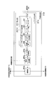
- the transmission signal generation unit 103 includes code channel signal processing units 106-1 to 106-N, a code multiplexing unit 107, an IFFT (Inversed Fast Fourier Transformation) unit 108, a multiplexing unit 109, a GI (Guard Interval: Guard interval) insertion section 110, retransmission control signal generation section 111, and pilot signal generation section 112.
- Each code channel signal generation section 106-1 to 106-N receives the information data of each code channel transmitted by code multiplexing and generates a signal of each code channel.
- N is the number of multiplexed codes.
- Each code channel signal generation section 106-1 to 106-N includes an encoding section 121, an interleaving section 122, a modulating section 123, and a spreading section 124.
- the encoding unit 121 adds redundant bits to the input information data so that the packet reception apparatus 200 that receives the information data can detect and correct errors.
- the encoding unit 121 receives a notification that the ACK signal has been received from the restoration unit 105 or receives information data
- the encoding unit 121 outputs information data with redundant bits added for the initial transmission packet
- information data with redundant bits added is output for the retransmission packet. Details of the encoding unit 121 will be described later.
- Interleaving section 122 rearranges the arrangement of output data series from encoding section 121.
- the modulation unit 123 performs data modulation such as QPSK (Quadrature Phase Shift Keying) and 16QAM (16 Quadrature Amplitude Modulation) on the output data from the interleaving unit 122. Generate modulation symbols. Note that the data modulation schemes for the initial transmission packet and the retransmission packet may be different. For example, the initial transmission packet may be modulated by 16QAM, and the retransmission packet may be modulated by QPSK.
- the spreading unit 124 multiplies the modulation symbol by a spreading code sequence corresponding to each code channel signal generation unit 106-1 to 106-N. Examples of spreading code sequences include orthogonal codes such as Walsh-Hadamard codes.
- the code multiplexing unit 107 code-multiplexes the output signal from each spreading unit 124 of each code channel signal generation unit 106-1 to 106-N.
- the IFFT unit 108 performs frequency-time conversion on the output signal from the code multiplexing unit 107 by IFFT (Inverse Fast Fourier Transform) or the like. Note that the transformation performed by the IFFT unit 108 may be other than the inverse fast Fourier transform IFFT as long as it can perform frequency-time transformation such as IDFT (Inverse Discrete Fourier Transform).
- IDFT Inverse Discrete Fourier Transform
- N code , SF, and N sub indicate the number of code multiplexes in the code multiplexing unit 107, the spreading rate of the spreading code multiplied by the spreading unit 124, and the number of subcarriers, respectively.
- C u, n indicates the value of the nth chip of the spreading code multiplied by the spreading section 124 of the signal generating unit 106-u for each code channel that generates the u th code channel signal.
- d u (m) indicates the m-th output signal (modulation symbol) of the modulation unit 123 of the code-channel signal generation unit 106-u that generates the u-th code channel signal.
- the multiplexing unit 109 multiplexes the output signal from the IFFT unit 108, the retransmission control signal output from the retransmission control signal generation unit 111, and the pilot signal output from the pilot signal generation unit 112.
- This multiplexing method may be any method such as time multiplexing or frequency multiplexing.
- the pilot signal generation unit 112 generates a pilot signal used for propagation path estimation.
- the retransmission control signal generation unit 111 generates a signal (retransmission control signal) for notifying the packet reception device 200 of the number of retransmissions of the signal of each code channel.
- the retransmission control signal may include notification of transmission parameters such as a data modulation scheme and the number of code multiplexes.
- the GI insertion unit 110 inserts a guard interval GI into the output signal of the multiplexing unit 109 and inputs it to the transmission unit 102.
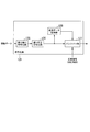
- FIG. 2 is a schematic block diagram showing the configuration of the encoding unit 121.
- the encoding unit 121 includes an error detection encoding unit 125, an error correction encoding unit 126, a puncturing unit 127, and a transmission data storage unit 128.
- the error detection encoding unit 125 performs error detection encoding such as CRC (Cyclic Redundancy Check) on the information data so that the packet receiving apparatus 200 that has received the information data can detect whether or not there is an error.
- the error detection bit is added to the information data and output.
- the error correction coding unit 126 performs error correction coding such as a turbo code, a convolutional code, and an LDPC (Low Density Parity Check) code on the output data from the error detection coding unit 125.
- CRC Cyclic Redundancy Check
- the error correction encoding unit 126 includes inner encoders 3001 and 3002 and an inner interleaver 3003.
- the error correction encoding unit 126 outputs three types of information bit sequences of systematic bit x, parity bit z, and parity bit z ′.
- the systematic bit x is the bit sequence itself input from the error detection encoding unit 125.
- the parity bit z is an output result obtained when the internal encoder 3001 performs the encoding process on the bit sequence from the error detection encoding unit 125.
- the parity bit z ' is an output result obtained by first interleaving the bit sequence from the error detection coding unit 125 by the internal interleaver 3003 and coding the result of the interleaving process by the internal encoder 3002.
- the inner encoder 3001 and the inner encoder 3003 may be the same encoder that performs the encoding of the same encoding method, or may be different encoders.
- a recursive convolutional encoder is used for both the inner encoder 3001 and the inner encoder 3002.
- the error correction encoding unit 126 will be described using a turbo code with the configuration shown in FIG.
- a unit in which error detection encoding unit 125 performs error detection encoding is a packet.
- error correction coding is performed in units of packets and packet signals are arranged in each code channel to be code-multiplexed.
- the signal of the packet arranged in each code channel is code-multiplexed, and a signal obtained by multiplexing the pilot signal and the retransmission control signal is called a frame, and the packet transmitting apparatus 100 transmits the signal in units of frames. .
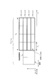
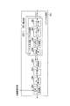
- FIG. 4 is a diagram illustrating an example of a frame configuration according to the present embodiment.
- the frame in FIG. 4 is an example in which packets 1 to 4 consisting of four OFDM symbols of length T s are code-multiplexed, and a pilot signal and a retransmission control signal are time-multiplexed in this code-multiplexed packet group. It is. T f indicates the packet length.
- the OFDM symbol consists of a GI section inserted by the GI insertion section 110 and an effective symbol section including output data from the signal generators 160-1 to 160-N for each code channel.
- error correction coding can be performed over a plurality of groups performing error detection coding. Further, error correction coding can be performed by grouping the data subjected to error detection coding into a plurality of groups and in groups.
- the puncturing unit 127 thins out the encoded bits that are output from the error correction encoding unit 126 based on a predetermined pattern group that is held (referred to as puncturing processing), and the amount of data to be transmitted. Control (control coding rate).
- puncturing processing a predetermined pattern group that is held
- Control control coding rate
- the puncturing unit 127 performs puncturing processing on the encoded bits received by requesting the transmission data storage unit 128 based on the predetermined pattern group described above.
- the predetermined pattern group held by the puncture unit 127 will be described later.
- the transmission data storage unit 128 stores the encoded bits generated by the error correction encoding unit 126 and, when requested by the puncture unit 127, outputs the encoded bits corresponding to the stored request.
- the transmission data storage unit 128 receives the NACK signal from the restoration unit 105, and the transmission data storage unit 128 receives the input of the signal and outputs the stored encoded bits to the puncture unit 127. May be.
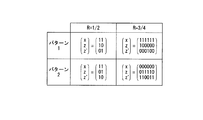
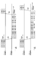
- FIG. 5 is a diagram illustrating an example of the predetermined pattern group described above held by the puncture unit 127.
- x is a bit string representing puncturing processing for data input from the error detection encoding unit 125 to the error correction encoding unit 126, that is, systematic bits including error detection bits and information data.
- “1” indicates that the bit at the corresponding position remains, and “0” indicates that the bit at the corresponding position is thinned out.
- z and z ′ are bit strings representing puncturing processing for redundant bits (parity bits z and parity bits z ′ in FIG. 3) generated from the systematic bits by the error correction coding unit 126.
- the values “1” and “0” of each bit of the bit string z and z represent the bits to be left and the bits to be thinned out as in the bit string x.
- the puncturing unit 127 performs the puncturing processing represented by these bit strings x, z, and z ′ on the systematic bits and redundant bits output from the error correction coding unit 126 or the transmission data storage unit 128, and FIG.
- a pattern group (a pattern corresponding to HARQ type II) that is a pattern in which only some patterns leave systematic bits, and all patterns are always systematic. It may be a pattern group (pattern corresponding to HARQ type III) that is a pattern that leaves bits.
- Chase combining CC Chose Combining
- IR Incmental Redundancy
- the output signal from the puncturing unit 127 punctured with the pattern 1 is transmitted from the antenna unit 101 by the transmitting unit 102 after the other processing of the transmission signal generating unit 103 described above is performed.
- the puncture unit 127 encodes the data transmitted from the transmission data storage unit 128 using the initial transmission packet signal. And a signal punctured with the same pattern 1 as the initial transmission packet signal is output as a retransmission packet signal.
- the puncturing unit 127 continues to output a punctured signal in the same pattern as the initial transmission packet signal until an ACK signal is input.
- the output data of the error correction coding unit 126 relating to the next information data different from the information data transmitted by the initial transmission packet signal is based on the pattern 1 or the pattern 2 Perform puncture processing.
- the output signal from the puncturing unit 127 punctured with the pattern 1 is transmitted from the antenna unit 101 by the transmitting unit 102 after the other processing of the transmission signal generating unit 103 described above is performed.
- the puncturing unit 127 continues to alternately output the signal punctured with the pattern 1 and the signal punctured with the pattern 2 until the ACK signal is input.
- the puncture process is performed on the output data of the error correction encoding unit 126 for the next information data different from the information data transmitted by the initial transmission packet signal based on the pattern 1. Do.
- the output data of error correction coding section 126 for different next information data may be transmitted without further retransmission.
- FIG. 6 is a schematic block diagram showing a configuration different from that of FIG.
- the error correction encoding unit 136, the puncturing unit 137, and the transmission data storage unit 138 are different from those in FIG.
- the transmission data storage unit 138 stores data subjected to error detection coding such as a cyclic redundancy check CRC by the error detection coding unit 125.
- the error correction encoding unit 136 performs error correction encoding such as a turbo code on the error detection encoded data from the error detection encoding unit 125.
- the error correction encoding unit 136 requests error detection encoded data from the transmission data storage unit 138 and the error detection encoding stored in the transmission data storage unit 138 Data is acquired and error correction coding is performed.
- the puncturing unit 137 punctures the output data from the error correction coding unit 136 based on a certain predetermined pattern group.
- the puncturing unit 137 performs puncturing processing on the output data from the error correction coding unit 136 based on a predetermined pattern group that may be received when a NACK signal is input as a response signal.
- the predetermined pattern group as with the puncture unit 127, for example, there is a puncture pattern shown in FIG.
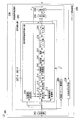
- FIG. 7 is a schematic block diagram showing the configuration of the packet reception device 200 according to the present embodiment.
- the packet reception device 200 is included in a mobile station device on the downlink and a base station device on the uplink by the wireless communication system.
- the relay station apparatus is provided in the downlink between the base station apparatus and the relay station apparatus.
- the packet reception device 200 includes a reception unit 202, a signal detection unit 203, a synthesis unit 204, a decoding unit 205, a received packet management unit 206, and a response signal generation unit 220.
- the antenna unit 201 receives a signal transmitted from the packet transmission device 100 or transmits a signal including a response signal generated by the packet reception device 200.
- the receiving unit 202 converts the signal from the packet transmission device 100 received by the antenna unit 201 into a frequency band capable of signal processing such as signal detection processing, and further performs filtering processing for band limitation, and the filtered signal. Convert analog signal to digital signal (Analogue to Digital conversion).
- the signal detection unit 203 receives the signal by the antenna unit 201 and performs signal detection on each of the initial transmission packet signal and the retransmission packet signal that the reception unit 202 converts into a digital signal. -1 to 207-P.
- the signal detectors 207-1 to 207-P for each received signal include a receiving unit for each packet signal received by requesting retransmission (including the first received signal before the retransmission request (initially received signal)). Based on the control information from the received packet management unit 206, signal detection processing such as removal of interference components and conversion into a data signal that can be decoded is performed on the signal from 202.
- P is the maximum number of the total of the number of packets received by requesting retransmission and the first received packet signal (initial transmission packet signal) before requesting retransmission.
- the output signal r p from the receiving unit 202 to the signal received in the p-th performs signal detection processing with the received signal for each signal detection unit 207-p.
- the reception unit 202 when the reception unit 202 receives the p-th packet signal and the signal detection unit 207-p for each received signal performs the i-th interference cancellation process on the p-th packet signal, the reception unit 202 again performs The received signal detection unit 207-u also performs the i′th (1 ⁇ i ′ ⁇ i) interference cancellation processing for the received uth (1 ⁇ u ⁇ p ⁇ 1) received packet signal. I do.
- the reception unit 202 receives the p-th packet signal and the signal detection unit 207-p for each received signal performs the i-th interference removal process on the p-th packet signal
- the received signal detection unit 207-u performs the i-th interference removal processing on the received packet signal of the u-th (1 ⁇ u ⁇ p ⁇ 1) that has already been received.
- the received packet management unit 206 acquires data related to transmission parameters such as the number of retransmissions of the retransmission packet signal, the data modulation scheme, and the number of code multiplexing from the retransmission control signal included in the received signal, and notifies the signal detection unit 203 of the data.
- reception unit 202 receives the p-th packet signal and the reception signal detection unit 207-p outputs data obtained by performing the i-th interference removal processing on the p-th packet signal
- the data output obtained by performing the i-th interference cancellation process on the p-th packet signal and the reception unit 202 receives the p-th packet signal, and the received-signal signal detection unit 207-u has already received the data again.
- the uth (1 ⁇ u ⁇ p ⁇ 1) received packet signal is combined with the data output obtained by performing the i ′ (1 ⁇ i ′ ⁇ i) interference removal process.
- the number of repetitions i ′ may be a fixed value of i ′> 1.
- reception unit 202 receives the p-th packet signal and the reception signal detection unit 207-p outputs data obtained by performing the i-th interference removal processing on the p-th packet signal
- the data output obtained by performing the i-th interference removal processing on the p-th packet signal and the reception signal unit for detecting received signal 207-u again receive the p-th packet signal when the receiving unit 202 receives the p-th packet signal.
- the u-th (1 ⁇ u ⁇ p ⁇ 1) received packet signal is combined with the data output obtained by performing the i-th interference cancellation processing.
- the i-th iteration the interference removing process was performed output g u from each received signals the signal detection unit 207-u for the output signal r u from the receiving unit 202 to a packet received in the u-th, i ( m) (where m is the index of the encoded bits constituting the packet, and the maximum value is the number of bits constituting the packet), the p-th retransmission packet signal is received, and the i-th iterative interference cancellation is performed.
- a generation expression of the output signal ⁇ p, i of the synthesis unit 204 when processing is performed can be expressed by Expression (2).
- ⁇ u, i represents a weighting factor given to the output g u, i (m) from the signal detection unit 207-u for each received signal, and many of the data modulation performed on g u, i (m) It is determined by the number of values, the coding rate, the spreading factor, the number of code multiplexes, etc.
- g u-1, i ( m) is the QPSK modulation
- g u, i (m) is when the 16QAM modulation has been performed, often toward the QPSK modulation demodulation accuracy than 16QAM modulation in the same channel state Therefore, by giving weights so that ⁇ u ⁇ 1, i > ⁇ u, i , the combining unit 204 can perform combining that reflects the demodulation accuracy for each data modulation scheme.
- the decoding unit 205 performs a decoding process corresponding to the encoding performed by the packet transmission device 100 that has transmitted the received signal, on the output signal from the synthesis unit 204.
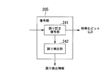
- FIG. 8 is a schematic block diagram showing the configuration of the decoding unit 205.
- the decoding unit 205 includes an error correction decoding unit 241 and an error detection unit 242.
- the reception unit 202 receives the p-th received packet (initial transmission packet or p-1th retransmission packet), and the received signal signal detection units 207-1 to 207-p receive the i-th reception packet. Is performed on the output signal ⁇ p, i from the synthesizing unit 204.
- the error correction decoding unit 241 of the decoding unit 205 performs error correction decoding processing for error correction coding such as turbo coding and convolution coding performed by the source packet transmission apparatus 100, and performs LLR (Log Likelihood) of coded bits.
- LLR Log Likelihood
- a soft decision output result such as Ratio (log likelihood ratio) is calculated and input to the error detection unit 242 of the decoding unit 205 and the interference removal unit 212 of the signal detection units 207-1 to 207-P for each received signal.
- decoding section 205 calculates a log likelihood ratio for output signal ⁇ p, i from combining section 204 , and calculates the log likelihood ratio for each bit of systematic bits and parity bits as signal detection section 207- 1 to 207-P are input to the interference canceller 212.
- the decoding unit 205 inputs a log likelihood ratio for the systematic bits to the error detection unit 242.
- the error detection unit 242 performs a hard decision process on the log likelihood ratio LLR of the coded bits, and performs packet detection by error detection such as cyclic redundancy check CRC (Cyclic Redundancy Check) performed by the packet transmitting apparatus 100 of the transmission source. An error detection process is performed on and error detection information is generated. Further, based on this error detection information, it is determined whether or not the canceller process by the interference removal unit 212 is repeated.
- CRC Cyclic Redundancy Check
- the signal detection units 207-1 to 207-P for each received signal are respectively the propagation path estimation unit 210, the received signal storage unit 211, the interference removal unit 212, the GI removal unit 213, the FFT unit 214, A propagation path compensation unit 215, a despreading unit 216, a demodulation unit 217, a deinterleave unit 218, and a depuncture unit 219 are provided.
- the parts constituting these signal detection units 207-1 to 207-P for each received signal include the control information from the received packet management unit 206, the spreading code of the despreading unit 216, the data modulation scheme of the demodulation unit 217, and the deinterleaving.
- transmission parameters regarding each part such as a rearrangement pattern of the unit 218 and a puncture pattern of the depuncture unit 219 are included, the operation is performed according to the control information.
- the propagation path estimation unit 210 estimates a propagation path (impulse response, transfer function, etc.) through which the reception signal has passed from the pilot signal included in the output signal from the reception unit 202. Note that the propagation path estimation unit 210 may estimate the propagation path using a control channel, a preamble, or the like instead of the pilot signal.
- the interference removal unit 212 generates a replica of an interference component for a desired signal using the propagation path estimation value output from the propagation path estimation unit 210 and the output signal from the decoding unit 205, and receives the generated interference component replica. The output signal from the unit 202 is removed.
- the GI removal unit 213 removes the guard interval GI added by the transmission / reception apparatus 100 in order to avoid distortion due to the delayed wave from the signal from which the interference removal unit 212 removed the interference component replica.
- the FFT unit 214 performs a Fourier transform process in which the signal from which the GI removal unit 213 has removed the guard interval GI is converted from a time domain signal to a frequency domain signal.
- the propagation path compensation unit 215 uses the propagation path estimation value from the propagation path estimation unit 210 to calculate a weighting factor for correcting propagation path distortion by ZF (Zero Forcing), MMSE (Minimum Mean Square Error), and the like, and this weighting factor Is multiplied by the frequency domain signal from the FFT unit 214 to perform propagation path compensation.
- the despreading section 216 performs despreading by multiplying the frequency domain signal that has been subjected to propagation path compensation by the propagation path compensation section 215 by the spreading code of the desired code channel, and extracts the code channel signal.
- the demodulation unit 217 performs demodulation processing such as QPSK and 16QAM on the signal extracted by the despreading unit 216, and calculates a soft decision result such as an encoded bit log likelihood ratio LLR.
- Re () represents the real part of a complex number.
- ⁇ is an equivalent amplitude after propagation path compensation. For example, if the propagation path estimated value in the k-th subcarrier is H (k) and the multiplied MMSE-based propagation path compensation weight W (k), ⁇ is W (k ) H (k).
- ⁇ (b 1 ) may be obtained by replacing the real part and the imaginary part of Equation (4), that is, ⁇ (b 0 ). It is possible to calculate based on the same principle for data subjected to other modulation such as 16QAM. Further, the demodulator 217 may calculate a hard decision result instead of a soft decision result.
- the deinterleaving unit 218 rearranges the bit arrangement corresponding to the interleaving pattern performed by the interleaving unit 122 of the transmission source packet transmitting apparatus 100, that is, the bit arrangement rearranging that is the reverse operation of the interleaving pattern. This is performed on the data series of soft decision results obtained by.
- the depuncturing unit 219 based on the puncture pattern performed by the puncturing unit 127 or 137 of the packet transmitting apparatus 100 that is the transmission source, performs a predetermined bit on the output data series from the deinterleave process. The depuncture process supplemented with is performed.
- the puncturing unit 127 or 137 converts the bit string “x1, z1, z1 ′, x2, z2, z2 ′” output from the error correction coding unit 126 or 136 into the coding rate of FIG.
- x1 and x2 are systematic bits
- z1, z2, z1 ′, and z2 ′ are redundant bits.
- the depuncture unit 219 receives the bit string “x r 1, z r 1, x r 2, z r 2 ′” and z1 thinned out by the puncture unit 127 or 137. 'A virtual value is inserted at a position corresponding to z2.
- the depuncture unit 219 includes the second bit and the third bit of the input bit string “x r 1, z r 1, x r 2, z r 2 ′”, “0” is inserted between the third bit and the fourth bit to generate and output the bit string “x r 1, z r 1,0, x r 2,0, z r 2 ′”.
- each of the received signal detection units 207-1 to 207-P performs the processing from the despreading to the puncturing unit for each code channel of the code-multiplexed received signal. I do.
- the reception signal storage unit 211 receives a notification of how many times a signal including a packet of transmission has been received, and when the notification is the number of times the signal detection unit for each received signal to which the unit belongs belongs, The received signal is stored, and when the notification is greater than the number of times the signal detection unit for each received signal to which the unit belongs belongs, the stored signal is output to the interference removal unit 212.
- the reception unit 202 when the reception unit 202 receives the first packet signal (initial transmission packet signal) in hybrid automatic retransmission HARQ, the reception signal storage unit 211 included in the signal detection unit 207-1 for each received signal The output signal from the receiving unit 202 of the packet signal is stored. Further, when the reception unit 202 receives the second and subsequent packet signals, the reception signal storage unit 211 included in the signal detection unit 207-1 for each received signal receives the stored first packet signal. The signal is input to the interference removal unit 212 included in the signal detection unit 207-1 for each signal.
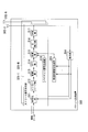
- FIG. 9 is a schematic block diagram illustrating the configuration of the interference removal unit 212.
- the interference removal unit 212 includes a replica generation unit 251 and a subtraction unit 252.
- the replica generation unit 251 generates a signal replica that the packet transmission device 100 that is the transmission source of the received signal will transmit using the log likelihood ratio LLR ⁇ p ′ of the encoded bit from the decoding unit 205. To do.
- the replica generation unit 251 when receiving a signal transmitted by the packet transmission device 100, the replica generation unit 251 generates a signal replica for the signal S (k) of the above-described equation (1).
- an interference replica is generated using the signal replica and the propagation path estimation value from the propagation path estimation unit 210.
- the subtracting unit 252 subtracts this interference replica from the input signal from the receiving unit 202 to remove the interference component.
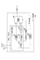
- FIG. 10 is a schematic block diagram illustrating a configuration of a replica generation unit 251 that generates an interference replica of intersymbol interference ISI.
- the replica generation unit 251 includes code channel replica generation units 257-1 to 257-N code , a code multiplexing unit 253, an IFFT unit 254, a GI insertion unit 255, and an interference replica generation unit 256.
- N code is the number of multiplexed codes of the received signal.
- Each code channel replica generation section 257-1 to 257-N code generates a signal replica for each code channel, and includes a puncturing section 261, an interleaving section 262, a symbol replica generating section 263, and a spreading section 264.
- Puncturing section 261 uses the same pattern as the puncture pattern applied by puncturing section 127 or 137 of packet transmitting apparatus 100, which is the transmission source, for logarithmic likelihood ratio LLR ⁇ p ′ of the encoded bit that is the output signal of decoding section 205. Puncture processing.
- the interleave unit 262 performs a bit arrangement rearrangement process on the output signal from the puncture unit 261 using the same pattern as the rearrangement pattern applied by the interleave unit 122 of the transmission source packet transmitting apparatus 100.
- the symbol replica generation unit 263 performs modulation such as QPSK modulation and 16QAM on the output signal from the interleaving unit 262 to generate a modulation symbol replica.
- the processing of the symbol replica generation unit 263 will be described using QPSK modulation as an example. If the log likelihood ratio LLR of the bits b 0 and b 1 constituting the QPSK modulation symbol is ⁇ (b 0 ) and ⁇ (b 1 ), a replica of the QPSK modulation symbol is given by Equation (5). However, j represents an imaginary unit. In other modulations such as 16QAM, it is possible to generate a symbol replica based on the same principle.
- Spreading section 264 multiplies the output signal from symbol replica generating section 263 by the spreading code sequence of each code channel, and generates a signal replica for each code channel.
- the code multiplexing unit 253 code-multiplexes the signal replica for each code channel generated by the code channel replica generation units 257-1 to 257-N code .
- the IFFT unit 254 performs frequency-time conversion by performing inverse Fourier transform on the output signal from the code multiplexing unit 253.
- the GI insertion unit 255 inserts the guard interval GI into the output signal from the IFFT unit 254.
- Interference replica generation section 256 generates an inter-symbol interference ISI interference replica using the output signal from GI insertion section 255 and the propagation path estimation value from propagation path estimation section 210.
- the intersymbol interference ISI to the packet signal by the retransmission control signal and the pilot signal can be similarly removed.
- the interference removal unit 212 the configuration in the case of removing the intersymbol interference ISI has been shown. It is also possible to remove interference components.
- the inter-code interference MCI interference replica code-multiplexes the output from the replica generation unit for each code channel other than the desired code channel, and performs IFFT processing on the code-multiplexed signal and inserts the GI, and then convolves the channel estimation value Can be generated.
- the interference replica r ′ p of the inter-code interference MCI generated by the replica generation unit 251 of the signal detection unit 207-p for each received signal in the i-th interference removal processing when the p-th packet is received . i can be expressed by equation (9-1).
- an interference removing unit that removes interference components can be arranged after the fast Fourier transform FFT processing by the FFT unit 214.
- the response signal generation unit 220 in FIG. 7 includes a data sequence including control data indicating the presence / absence of a packet error based on the error detection result in the decoding unit 205 when the iterative processing of the signal detection unit 203 and the decoding unit 205 is performed a prescribed number of times. And a response signal is generated by performing signal processing such as error correction coding and data modulation. Further, the response signal is converted into an analog signal (Digital to Analog conversion), further converted into a transmittable frequency band, and transmitted to the packet transmitting apparatus 100 via the antenna unit 201.
- the communication method of the response signal may be any method such as OFDM or single carrier modulation method, and it is only necessary that the processing of the restoration unit 105 in the packet transmission device 100 of the communication partner corresponds.
- the response signal generation unit 220 when a signal indicating “no packet error” is input from the decoding unit 205, the response signal generation unit 220 generates an ACK signal indicating that reception has been correctly completed as a response signal. Then, the packet is transmitted to the source packet transmitting apparatus 100. Further, when a signal indicating “there is a packet error” is input from the decoding unit 205, the response signal generation unit 220 generates a NACK signal requesting retransmission of the packet as a response signal, and via the antenna unit 201, The packet is transmitted to the source packet transmission device 100.
- a retransmission request is made in code channel units (packet units).
- the present invention is not limited to this, and it is sufficient that at least one error detection code is added in the retransmission request unit.
- the signal detection unit 203 of the data receiver device 200 of this embodiment includes a plurality of signal detection units for each received signal, and the signal of the initial transmission packet or the retransmission packet is processed in each processing of signal detection and decoding. Although signal detection is performed in parallel for a plurality of received signals, the signal detection unit 203 includes only one signal detection unit for each reception signal, and the signal detection unit for each reception signal includes a plurality of signal detection units. You may make it perform signal detection sequentially with respect to a received signal.
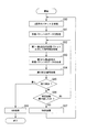
- FIG. 11 is a flowchart for explaining the operation of the packet receiving apparatus 200.
- the reception packet management unit 206 determines how many times (here, the number of packets included in the signal from the retransmission control signal of the received signal) q), and the received signal storage unit 211 of the received signal signal detection unit 207-q, which is in charge of processing the qth packet as the determination result, stores the signal data of the received packet. (S11).
- the signal detection units 207-1 to 207-q for each received signal read from the received signal storage unit 211 the signals of the first packet (initial transmission packet) to the signal of the qth packet, respectively.
- step S12 signal detection processing is performed (S12).
- the processing content of step S12 will be described in detail with reference to FIG.
- the signals of the q-th packet and all the packets before the q-th packet are again signaled.
- the detection process is described as being performed, the signal detection process may be performed again on the signal of one or more of the packets before the q-th packet.
- the synthesizer 204 synthesizes the data signals detected by the received signal signal detectors 207-1 to 207-q (S13). That is, the data signal detected from the signals of the first to qth packet is synthesized.
- the error correction decoding unit 241 of the decoding unit 205 performs error correction decoding processing on the data signal combined by the combining unit 204 (S14). Further, the error detection unit 242 of the decoding unit 205 performs error detection processing on the error correction decoding process result to determine whether there is an error (S15). If it is determined in step S15 that there is no error, the response signal generation unit 220 generates an ACK signal and transmits it to the transmission source packet transmission apparatus 100 (S18).
- decoding section 205 removes the interference replica generated using the log likelihood ratio LLR of the encoded bit after the error correction decoding process from the received signal.
- the number of repetitions of a series of iterative interference removal processes of the used signal detection process, synthesis process, and decoding process is determined (S16).
- the process returns to step S12, and as described above, the interference replica is set for the first received packet signal (initially transmitted packet signal) to the qth received packet signal. Signal detection processing using removal from the received signal is performed, and the subsequent synthesis processing and decoding processing are performed as described above.
- the response signal generation unit 220 when it is determined in step S16 that the number of repetitions has reached the predetermined number, the response signal generation unit 220 generates a NACK signal and transmits the NACK signal to the transmission source packet transmission apparatus 100 via the antenna unit 201. Transmit (S17). Then, the process returns to step S10, and the reception unit 202 receives the signal of the q + 1-th packet next to the packet received in the previous step S10 transmitted by the packet transmission device 100 that has received this NACK signal.
- FIG. 12 shows a signal detection unit 207-p for each received signal that performs signal detection processing on the received signal including the packet transmitted at the p-th time in the hybrid automatic retransmission HARQ in step S12 of FIG. It is a flowchart which shows operation
- the signal detection unit 207-p for each received signal notified from the received packet management unit 206 of the number of transmission packets (here, the qth packet) included in the signal received by the reception unit 202 is Compares the p-th in charge of signal processing with the q-th notification from the received packet management unit 206 (S100), and when p is greater than q (p> q), the process ends.
- step S102 when it is determined in step S102 that the process is the second or later (i> 1), the encoded bits generated by the error correction decoding unit 241 of the decoding unit 205 in the previous (i ⁇ 1) iteration process. Is obtained by the replica generation unit 251 of the interference removal unit 212 (S104). Next, the replica generation unit 251 generates an interference replica using the log likelihood ratio LLR of the acquired encoded bits (S105).
- the subtraction unit 252 of the interference removal unit 212 subtracts the interference replica generated by the replica generation unit 251 from the signal read in step S101 (the signal of the p-th packet). Thus, the interference component is removed (S106).
- the GI removal unit 213 removes the guard interval GI from the signal from which the interference replica is subtracted (S107).
- the FFT unit 214 performs time-frequency conversion by performing fast Fourier transform on the signal from which the guard interval GI is removed, and obtains a signal in the frequency domain (S108).
- the propagation path distortion compensation unit 215 multiplies the frequency domain signal by an MMSE (Minimum Mean Square Error) weight based on the propagation path estimation value (S109).
- MMSE Minimum Mean Square Error
- the despreading unit 216 performs a despreading process for multiplying the multiplication result by a spreading code of a desired code channel, and the demodulating unit 217 demodulates the data modulation for the despreading process result. Processing is performed (S110).
- the deinterleaving unit 218 performs deinterleaving on the demodulation processing result, which is rearrangement of bit positions corresponding to the reverse operation of the interleaving unit 122 of the packet transmission device 100 (S111).
- the depuncture unit 219 performs a depuncture process on the deinterleave result (S112), and then outputs a signal of the depuncture process result to end the process.
- FIG. 13 is a sequence diagram illustrating an operation example of a communication system to which hybrid automatic retransmission HARQ having the packet transmission device 100 and the packet reception device 200 is applied.
- the packet transmission device 100 transmits a first frame in which a packet including encoded data of the information data A1 is arranged, and performs first transmission (initial transmission packet transmission) to the packet reception device 200 (Sa1). ).
- the first transmission packet is a packet including data obtained by puncturing the encoded data of the information data A1 with a predetermined puncture pattern.
- the packet reception device 200 receives the first transmission packet, the first reception packet is used to perform signal processing such as interference removal processing, demodulation, and decoding to detect data errors.
- the packet reception device 200 transmits a NACK signal to the packet transmission device 100 (Sa2).
- the packet transmitting device 100 transmits again the second frame in which the packet including the encoded data of the information data A1 is arranged, and retransmits the packet to the packet receiving device 200 (second packet transmission). ) Is performed (Sa3).
- the packet reception device 200 When receiving the second transmission packet transmitted in the sequence Sa3, the packet reception device 200 performs signal detection including interference removal processing for both the first and second packets, and signal processing such as combining and decoding, Is repeated to detect errors in the decoded data.
- the packet receiving device 200 transmits a NACK signal (Sa4).
- packet transmission apparatus 100 and packet reception apparatus 200 Packet retransmission is performed (Sa5 to Sa7), and the packet receiving apparatus 200 transmits an ACK signal for the packet signal including the information data A1 (Sa8).
- the packet transmitting apparatus 100 receives this ACK signal, the packet transmitting apparatus 100 transmits the information data The packet transmission including the encoded data of A1 ends. Then, the packet transmission device 100 performs the first transmission of the packet including the encoded data of the information data different from the information data A1.
- FIG. 14 shows a case where three packets are code-multiplexed and transmitted for each frame.
- the packet transmission device 100 arranges the first to third packets 1 to 3 in the first frame and transmits them to the packet reception device 200 (Sb1).
- the signal processing unit 207-1 for each received signal of the packet receiving apparatus 200 performs signal detection processing using removal of the interference replica from the received signal for each packet of the first frame.
- a series of repetitive interference removal processing of decoding processing in the decoding unit 205 is performed (since all packets are initial transmission packets, no synthesis is performed). Assume that after the interference cancellation process is repeated a predetermined number of times, no error is detected in packet 1 and errors are detected in packets 2 and 3.
- the packet receiving apparatus 200 transmits an ACK signal for the packet 1 and a NACK signal for requesting retransmission for the packets 2 and 3 to the transmitting apparatus 100 (Sb2).
- the received signal storage unit 211 of the signal processing unit 207-1 for each received signal stores the initial transmission packet signals of the packets 1, 2 and 3.
- the packet transmitter 100 Based on the response signals (ACK signal and NACK signal) from the packet receiver 200, the packet transmitter 100 retransmits the packets 2 and 3 (second transmitted packet) and newly transmits the initial packet 4 of the packet 4. Are code-multiplexed to generate a second frame, which is transmitted to the receiving apparatus 200 (Sb3).
- the signal processing unit 207-2 for each received signal performs an interference replica for the packets 2 to 4 of the received second frame.
- the signal detection process using the removal from the received signal is performed.
- the signal processing unit 207-1 for each received signal again performs signal detection processing using the removal of the interference replica from the received signal for the packets 1 to 3 received in the first frame. Since packet 1 of the first frame has already been correctly received, signal detection processing is not performed, and in order to generate an interference replica for packets 2 and 3, a signal replica of packet 1 generated from the hard decision result is used. It may be used.
- synthesizer 204 outputs the data sequence of packet 2 of the first frame output from signal processing unit 207-1 for each received signal and the signal processing unit 207-2 for each received signal.
- the data series of packet 2 of the second frame is synthesized and output to decoding section 205.
- the combining unit 204 also receives the data sequence of the packet 3 of the first frame output from the signal processing unit 207-1 for each received signal and the signal processing unit 207-2 for each received signal.
- the data series of the packet 3 of the second frame to be output is synthesized and output to the decoding unit 205.
- combining section 204 does not combine the data sequence of packet 4 of the second frame output from signal processing section 207-2 for each received signal without decoding with other packets. Output to.
- Decoding section 205 performs a decoding process on each data series of packets 2 to 4 output from combining section 204.
- the coded bit LLRs for the data sequences of packet 2 and packet 3 are output to signal processing unit 207-1 for each received signal and signal processing unit 207-2 for each received signal, and for the data sequence of packet 4
- the encoded bit LLR is output to the signal processing unit 207-2 for each received signal.
- Each signal processing unit 207-1 and signal processing unit 207-2 for each received signal uses the encoded bit LLR for the data series of packets 2 to 4 from the decoding unit 205 again from the received signal of the interference replica.
- the signal detection process using the removal of.
- a series of repeated interference removal processing including signal detection processing, synthesis processing, and decoding processing using the removal of the interference replica from the received signal is repeated a predetermined number of times. It is assumed that the error detection unit 242 does not detect an error for all of the packets 2 to 4 as a result of the signal processing at the time of receiving the second frame.
- the packet receiving device 200 transmits an ACK signal as a response signal to each of the packets 2 to 4 toward the transmitting device 100 (Sb4).
- the interference removal unit 212 that repeatedly removes interference is provided.
- the interference removal processing for the received retransmission packet, the interference removal processing for the packet received before the received retransmission packet, and the interference removal processing are detected.
- the signal synthesizing process and decoding process are repeated.
- an interference replica is generated based on the synthesized signal including the newly received packet.
- An accurate interference replica can be used, and the data decoding accuracy for the initial transmission packet and the retransmission packet can be improved. As a result, it is possible to reduce the number of repetitions of interference cancellation processing (signal detection), combining and decoding, and to reduce the number of retransmissions of hybrid automatic retransmission HARQ.
- a parallel interference canceller (PIC: Parallel Interference Canceller) is used as an interference canceller using the interference canceller 212 of the packet reception device 200, but a sequential interference canceller (SIC: Successive Interference Canceller). ) May be used.
- the present embodiment has been described using the packet reception device 200 including the interference canceller as a communication device that performs signal detection processing on packet signal data received before the retransmission packet when the retransmission packet is received.
- a communication apparatus that performs iterative processing using a turbo concept such as a turbo equalizer that repeats signal detection by equalization processing using the decoding processing result and decoding processing of the processing result of the equalizer Good.
- the signal processing units 207-1 to 207-P for each received signal perform repeated interference cancellation processing on all packets received before the retransmission packet when receiving the retransmission packet.
- the interference removal process may be repeatedly performed only on a part of the packets received before the retransmission packet.
- the combining unit 204 has been described as combining signals for all received initial transmission packets and retransmission packets, for example, a predetermined number or less from the one having the higher reception power, Only the signals of some packets may be combined. Further, when the combining unit 204 combines only some of the packet signals, the signal to be combined may always include the signal of the initial transmission packet. In particular, when increasing redundant IR is used for hybrid automatic retransmission, the signal of the initial transmission packet is always included in the signal to be combined so that the systematic bit signal is not included in the signal to be combined. It is possible to suppress a significant decrease in the accuracy of the result of combining specific bits.
- a packet reception apparatus that performs stream separation using repetitive processing such as V-BLAST and successive interference canceller SIC as stream separation in MIMO (Multi-Input Multi-Output) transmission
- MIMO Multi-Input Multi-Output
- hybrid automatic retransmission HARQ When the retransmitted packet is received, the repeated stream separating process for the received retransmitted packet and the repeated stream separating process for the packet received before the received retransmitted packet are performed again, And you may make it perform a decoding process.
- MIMO Multi-Input Multi-Output
- the packet reception device (second communication device) 200a of the present embodiment has a configuration for combining a signal that has been subjected to interference component removal processing for each retransmission packet before performing demodulation processing, Applied to hybrid automatic retransmission HARQ using chase combining CC.
- FIG. 15 is a schematic block diagram showing the configuration of the packet reception device 200a in the present embodiment.
- 15 includes a receiving unit 202, a GI removing unit 213a, an FFT unit 214, signal detection units 207a-1 to 207a-P for each received signal, a combining unit 204a, a despreading unit 216a, a demodulating unit 217, An interleaving unit 218, a depuncturing unit 219, a decoding unit 205a, a received packet management unit 206a, and a response signal generation unit 220 are provided.
- parts (201, 202, 214, 217 to 220) corresponding to the parts in FIG.
- the signal detection unit 203a includes signal detection units 207a-1 to 207a-P for each received signal.
- the GI removal unit 213a differs from the GI removal unit 213 in FIG. 7 in that the input signal is an output signal from the reception unit 202, and avoids distortion due to a delayed wave among the output signals from the reception unit 202. Therefore, the guard interval GI added by the transmission apparatus 100 is removed.
- Received packet management section 206a obtains data related to transmission parameters such as the number of retransmissions, data modulation, and number of multiplexed codes from the retransmission control signal included in the frequency domain signal converted by FFT section 214, and receives received signal detection section 207a- 1 to 207a-P are notified.
- the signal detectors 207a-1 to 207a-P for each received signal receive the FFT unit 214 for each packet signal received by requesting retransmission (including the first received signal (initially received signal) of the signal requesting retransmission). Based on the control information from the received packet management unit 206a, the interference signal is removed and the propagation path is compensated for the output signal from.
- P is the maximum number of the total number of packets received by requesting retransmission and the first received packet signal (signal of the initial transmission packet) of the signal requested to be retransmitted.
- the output signal r p from the FFT unit 214 for the received signal to the p-th performs the removal of interference components in each received signals the signal detection unit 207a-p.
- the reception unit 202 when the reception unit 202 receives the p-th packet signal (the signal of the p-1th retransmission packet), the signal detection units for each received signal 207a-p detect the p-th packet signal. Then, the received signal detection unit 207a-u performs the interference removal process on the received packet signal of the u-th time (1 ⁇ u ⁇ p ⁇ 1) that has already been received.
- the reception unit 202 receives the p-th packet signal and the signal detection units 207a-p for each received signal perform the i-th interference removal processing on the p-th packet signal, at the same time, the existing signal again Also for the received u-th received packet signal (1 ⁇ u ⁇ p ⁇ 1), the received signal detection unit 207a-u performs the i′th (1 ⁇ i ′ ⁇ i) -th interference removal.
- i ′ i
- Each of the received signal detection units 207a-1 to 207a-P includes a propagation path estimation unit 210a, an interference removal unit 212a, a propagation path compensation unit 215a, and a received signal storage unit 211a.
- the parts constituting these signal detection units 207a-1 to 207a-P for each received signal operate based on control information from the received packet management unit 206a.
- the propagation path estimation unit 210a estimates a propagation path (impulse response, transfer function, etc.) through which the received signal has passed from the pilot signal included in the output signal from the FFT unit 214. Note that channel estimation using a control channel, a preamble, or the like may be used.
- the interference removal unit 212a generates a replica of the interference component using the propagation path estimation value that is the output of the propagation path estimation unit 210a and the output signal from the decoding unit 205a, and outputs the generated interference replica to the output signal of the FFT unit 214. Remove from.
- the propagation path compensation unit 215a calculates a weighting coefficient for correcting propagation path distortion by ZF (Zero Forcing), MMSE (Minimum Mean Square Error), etc., using the propagation path estimation value that is the output of the propagation path estimation unit 210a.
- the weighting coefficient is multiplied by the output signal from the interference removing unit 212a.
- the reception signal storage unit 211a stores the frequency domain signal input from the FFT unit 214 in the signal detection unit for each received signal to which it belongs, and stores the input from the FFT unit 214 in the reception processing unit for each reception signal that does not belong.
- the output frequency domain signal is output to the interference removal unit 212a.
- the interference removal unit 212a is configured by a replica generation unit 251a and a subtraction unit 252a as shown in FIG. 16 as in the interference removal unit 212 of FIG. 7 in the first embodiment, but the input signal is an FFT unit. 214 or the frequency domain signal from the received signal storage unit 211a.
- the subtraction unit 252a subtracts the replica signal generated by the replica generation unit 251a from the frequency domain signal from the FFT unit 214.
- the subtraction unit 252a of the signal detection units 207a-p for each received signal outputs the output signal R ′′ n, p, for the n-th code channel in the i-th interference cancellation process .
- i (k) is calculated as shown in Equation (10), where R p (k) is the data of the p-th received packet, and R ′ p, i ⁇ 1 (k) is from the replica generation unit 251a.
- the replica generation unit 251a generates a replica of the interference component using the log likelihood ratio LLR of the encoded bit from the decoding unit 205a and the propagation path estimation value from the propagation path estimation unit 210a.
- FIG. 16 shows, as an example, the configuration of the replica generation unit 251a when generating an interference replica of inter-code interference MCI.
- the replica generation unit 251a includes code channel replica generation units 257-1 to 257-N code , a code multiplexing unit 253a, and an interference replica generation unit 256a.
- N code is the number of code multiplexes of the received signal.
- Each code channel replica generation section 257-1 to 257-N code generates a signal replica for each code channel represented by Expression (11) based on the decoding result of the number of repetitions i.
- S ′′ p, n, i (k) is a replica calculated by the replica generation unit 257-n for each code channel based on the decoding result of the i-th iteration when receiving the p-th packet.
- D ′ p, n, i are output signals from the symbol replica generation unit 263.
- the code channel replica generation units 257-1 to 257-N code are a puncture unit 261 and an interleaving unit 262, respectively.
- a symbol replica generation unit 263, and a spreading unit 264 are the same as the respective units shown in FIG. is there.
- the code multiplexing unit 253a code-multiplexes the signal replica for each code channel generated by the code channel replica generation units 257-1 to 257-N code , excluding any one code channel. That is, the code multiplexing unit 253a includes first code signal replica other than the channel, the second code signal replicas except for the channel ⁇ ⁇ ⁇ N code th code channel and code multiplexing and so signal replicas except for the signal Replicas are generated only for N code that is the number of multiplexed codes.
- the interference replica generation unit 256a generates an inter-code interference MCI replica for each code channel by multiplying each of the code multiplexed signal replicas by a propagation path estimation value.
- Interference replica generation section 256a that is, replica generation section 251a, when receiving the p-th packet, inter-code interference MCI replica signal R ′ of the k-th subcarrier for the n-th code channel based on the decoding result of the i-th iteration n, p, i (k) are calculated as shown in equation (12).
- H ′ (k) is a transfer function of the propagation path estimation value of the kth subcarrier.
- the synthesis unit 204a synthesizes the output data series from each of the received signal detection units 207a-1 to 207a-P. That is, when receiving section 202 receives the p-th packet signal, combining section 204a is a signal that has been subjected to propagation path compensation by removing interference components from the first to p-th packet signals. Then, the signal before demodulation processing is synthesized.
- the nth code channel from the signal detection unit 207a-p for each received signal (specifically, the propagation path compensation unit 215a of the signal detection unit 207a-p for each received signal) for the output signal R p (k) from the FFT unit 214 Output G p, n (k) (where k is the subcarrier index), the output signal ⁇ p, n for the nth code channel of the combining unit 204a when the p-th packet signal is received is Equation (13) is obtained.
- the synthesizing unit 204a repeatedly performs interference removal processing by the reception signal-by-reception signal detection unit 207a-1 to reception signal-by-reception signal detection unit 207a-p, and performs synthesis processing each time an interference-removed signal is output.
- the above-described interference replica generation unit 256a is configured to remove inter-code interference MCI as an example, each interference component can be generated by generating interference replicas such as inter-carrier interference ICI and inter-symbol interference ISI. Can be removed.
- the despreading unit 216a performs despreading by multiplying the output signal from the combining unit 204a by the spreading code of the corresponding code channel.
- the demodulation unit 217, deinterleave unit 218, and depuncture unit 219 perform the same operations as the demodulation unit 217, deinterleave unit 218, and depuncture unit 219 shown in FIG. 7 of the first embodiment.
- the decoding unit 205a performs the same operation as the decoding unit 205 shown in FIG. 7 of the first embodiment on the output signal of the depuncture unit 219.
- the received signal is a code-multiplexed signal
- signal detection units 207a-1 to 207a-P for each received signal and a combining unit 204a are provided for each code channel of the code-multiplexed received signal.
- the despreading unit 216a, the demodulating unit 217, the deinterleaving unit 218, the depuncturing unit 219, and the decoding unit 205a perform processing.
- the despreading unit 216a, demodulating unit 217, deinterleaving unit 218, and depuncturing unit 219 include the control information from the received packet management unit 206a and the operation of each unit such as a spreading code, modulation scheme, interleave pattern, and depuncture pattern. In the case where the transmission parameter relating to includes, the operation is performed based on the control information.
- the retransmission is performed.
- the packet reception device 200a has a configuration in which the signal before demodulation is combined with the initial transmission packet, the signal, and the signal of the retransmission packet.
- the retransmission is performed.
- transmitted packets are spatially multiplexed using MIMO (Multi Input Multi Output).
- the communication system according to the present embodiment includes a packet transmission device (first communication device) 500 and a packet reception device (second communication device) 600.
- the packet reception device 600 is an iterative sequential interference canceller (SIC).
- the other stream signal is removed by the above-described method, and when the retransmission packet signal is received, the signal of the other stream is also removed from the packet signal data received before the retransmission packet by the repetitive sequential interference canceller.
- a stream represents a signal sequence transmitted from each transmission antenna. That is, signals transmitted from the same transmission antenna are signals of the same stream, and signals transmitted from different transmission antennas are different streams. Signal.
- an OFDM method Orthogonal Frequency Division Multiplexing
- Interference means other multiplexed signals. That is, for example, if signals P 1 and P 2 are spatially multiplexed, a signal P 2 is an interference for the signal P 1, the signal P 1 is an interference for the signal P 2.
- the interference cancellation process is a process for removing interfering signals reproduced signal (replica) from the received signal, for example, when detecting a signal P 2 is used to remove a replica of the signal P 1 from the received signal the signal .
- FIG. 17 is a schematic block diagram showing the configuration of the packet transmission device 500 according to the present embodiment.
- the packet transmission device 500 is included in a downlink base station device and an uplink mobile station device in a wireless communication system.
- the relay station apparatus is provided in the downlink between the relay station apparatus and the mobile station apparatus.
- the packet transmission apparatus 500 includes stream signal generation units 501-1 to 501-N (where N is the number of streams), antenna units 502-1 to 502-N, a retransmission control signal generation unit 503, and a restoration unit 504.
- the packet transmission device 500 transmits N stream signals generated from different pieces of information data from the N antenna units 502-1 to 502-N at the same time. Further, the packet transmission device 500 restores a signal including a response signal from the packet reception device 600.
- the restoration unit 504 converts the signal received from the packet reception device 600 via the antenna unit 502-1 into a frequency band that can be restored, filtering processing that limits the passband, and conversion from an analog signal to a digital signal ( (A / D conversion). Further, the restoration unit 504 performs reception signal restoration processing such as data demodulation and error correction decoding on the digital signal as a result of the A / D conversion, extracts a response signal included in the signal from the packet reception device 600, and outputs the packet The reception success / failure information is notified to the encoding unit 511 and the retransmission control signal generation unit 503.
- the restoration unit 504 has a function capable of restoring received signal processing based on a transmission method of a signal transmitted by the packet reception device 600.
- the restoration unit 504 is described as being connected to the antenna unit 502-1 and receiving via the antenna unit 502-1, but may be received via any antenna unit.
- the stream signal generation unit 501 generates a transmission data signal for each stream from information data input from the outside (for example, a MAC unit (Media Access Control Layer) not shown).
- the stream signal generation unit 501 includes an encoding unit 511, an interleaving unit 512, a modulation unit 513, an IFFT unit 514, a pilot signal generation unit 518, a multiplexing unit 515, a GI insertion unit 516, and a transmission unit 517.
- Encoding section 511 adds redundant bits to the bit sequence of information data input from the outside so that packet receiving apparatus 600 can detect and correct errors.
- the encoding unit 511 includes the error detection encoding unit 125, the error correction encoding units 126 and 136, the puncture units 127 and 137, and the transmission shown in FIG. Data storage units 128 and 138 are provided.
- the encoding unit 511 transmits the data of the initial transmission packet or the data of the retransmission packet according to the response signal from the packet receiving apparatus 600 to the data signal (packet) for each stream output from each of the stream signal generation units 501-1 to 501-N. Output encoded bits.
- a packet is generated for each stream, and error correction coding is performed for each packet (for each stream).
- the puncture pattern of the puncture process performed by the encoding unit 511 includes, for example, the puncture pattern illustrated in FIG. 5 as in the first and second embodiments.
- the interleave unit 512 rearranges the bit arrangement of the output data series of the encoding unit 511.
- Modulation section 513 performs data modulation such as QPSK or 16QAM on the output data from interleaving section 512 to generate modulation symbols. Note that the data modulation method may be different for each stream.
- the IFFT unit 514 performs frequency-time conversion on the modulation symbol from the modulation unit 513 by inverse fast Fourier transform IFFT (Inverse Fast Fourier Transform) or the like to generate a time domain signal.
- Multiplexing section 515 multiplexes the output signal from IFFT section 514, the pilot signal output from pilot symbol generation section 518, and the retransmission control signal output from retransmission control signal generation section 503. Pilot signal generation section 518 generates a pilot signal used for channel estimation of each stream signal. Preferably, an orthogonal pilot signal is generated for each stream.
- the retransmission control signal generation unit 503 generates a signal (retransmission control signal) for notifying the packet reception device 600 of the number of retransmissions of each stream signal according to the success / failure information from the restoration unit 504.
- the retransmission control signal is multiplexed with the stream in the stream signal generation unit 501-1.
- the retransmission control signal may include notification of transmission parameters such as the data modulation scheme used by the modulation unit 513 and the coding rate of the coding unit 511.
- the GI insertion unit 516 inserts a guard interval GI (Guard Interval) into the output signal of the multiplexing unit 514.
- the transmission unit 517 performs conversion of the output signal from the GI insertion unit 516 into an analog signal (D / A conversion), filtering processing for band limitation, and conversion to a transmittable frequency band. Similar processing is performed in each of the stream signal generation units 501-1 to 501-N, and the output signals from the respective stream signal generation units 501-1 to 501-N are sent from different antenna units 502-1 to 502-N.
- the initial transmission packet or the retransmission packet transmitted by the packet transmission device 500 is spatially multiplexed.
- Signals output from antenna units 501-1 to 501-N are referred to as stream 1 to stream N, respectively.
- the same stream is transmitted from the same antenna.
- the same stream may be transmitted from a different antenna for each retransmission.
- the case where the same stream is retransmitted from the same antenna in the packet transmission device 500 will be described.
- FIG. 18 is a schematic block diagram showing the configuration of the packet reception device 600 in this embodiment.
- 18 includes antenna units 601-1 to 601 -M (where M is the number of reception antennas), signal processing units for each antenna 602-1 to 602-M, received packet management unit 603, and received signal processing unit 604.
- the response signal generation unit 605 is provided.
- the per-antenna reception processing units 602-1 to 602-M perform reception processing of signals received via the corresponding antenna units 601-1 to 601-M.
- Each antenna reception processing unit 602-1 to 602-M includes a reception unit 610, a GI removal unit 611, an FFT unit 612, and a propagation path estimation unit 613.
- the reception processing unit 602-1 for each antenna will be described on behalf of the reception processing units 602-1 to 602-M for each antenna.
- the receiving unit 610 converts the signal from the packet transmission device 500 received via the antenna unit 601-1 into a frequency band capable of signal processing such as signal detection processing, filtering processing for band limiting, and analog signals as digital signals.
- a / D conversion to be converted into Propagation path estimation section 613 uses antenna signals 501-1 to 501-N of packet transmission apparatus 500 and antenna section 601 of packet reception apparatus 600 using a pilot signal included in the digital reception signal output from reception section 610. -1 to estimate the propagation path characteristic, and calculate the propagation path estimated value.
- the propagation path estimation unit 613 may calculate the propagation path estimation value using other signals that can estimate the propagation path, such as a control channel and a preamble.
- the GI removal unit 611 removes the guard interval GI from the data signal included in the digital reception signal.
- the FFT unit 612 converts the output signal of the GI removal unit 611 into a frequency domain signal by performing a fast Fourier transform FFT.
- the per-antenna reception processing units 602-2 to 602-M perform the same processing as the per-antenna reception processing unit 602-1.
- Equation (14) the signal R p (k) in the k-th subcarrier of the p-th received packet in hybrid automatic retransmission HARQ is expressed by Equation (14). It can be expressed as However, H p (k) is a propagation path characteristic between the transmission antenna and the reception antenna, S p (k) is a transmission signal for each transmission antenna, and N (k) is a noise for each reception antenna. , T represents a transposed matrix.
- Received packet management section 603 obtains data related to transmission parameters such as the number of retransmissions of each stream and data modulation transmitted from antenna sections 501-1 to 501-N of packet transmission apparatus 500 from a retransmission control signal included in the received signal. Then, the received signal processing unit 604 is notified. Received signal processing section 604 receives propagation path estimated values output from propagation path estimating section 613, data relating to transmission parameters of each packet output from received packet management section 603, and reception processing sections 602-1 to 602- for each antenna. A data signal output from M is used to detect a bit sequence of information data transmitted from antenna units 501-1 to 501-N of packet transmission apparatus 500, and a bit sequence of information data and an error detection result are output. . Details of the operation of the reception signal processing unit 604 will be described later.
- the response signal generation unit 605 generates a response signal based on the error detection result output from the reception signal processing unit 604, and transmits the response signal via the antenna unit 601-1, thereby transmitting the source packet.
- the transmission device 500 is notified of the necessity of retransmission. That is, the response signal generation unit 605 generates a NACK signal indicating that retransmission is necessary when the error detection result includes an error, and generates an ACK signal indicating that retransmission is not required when the error detection result indicates that there is no error. Note that the response signal generation unit 605 has been described as transmitting the generated response signal via the antenna unit 601-1, but may be transmitted from any antenna.
- FIG. 19 is a schematic block diagram showing a configuration for performing MIMO stream separation using repetitive SIC (Successive Interference Canceller) as the received signal processing unit 604.
- the reception signal processing unit 604 includes a signal detection unit 1601 including signal detection units 1601-1-1 to 1601-NP for each received signal, synthesis units 1609-1 to 1609-N, and decoding units 1610-1 to 1610-N. It comprises.
- N is the number of streams
- P is the total number of the maximum number of times that a retransmission packet is retransmitted due to a retransmission request and the first received packet signal (signal of an initial transmission packet) of the signal requested for retransmission, that is, one time.
- the signal detection units for the received signals 1601-1-p to 1601- Np performs interference cancellation processing on the pth received packet. Simultaneously with this processing, the received signal detection units 1601-1-u to 1601-Nu also interfere with the received packet signal of the u-th received (1 ⁇ u ⁇ p ⁇ 1). Perform removal processing. For example, the FFT 612 outputs a signal for the p-th received packet, and the received signal detection units 1601-1-p to 1601-Np remove the i-th interference cancellation for the p-th received packet signal.
- the received signal detection units 1601-1-u to 1601-Nu are also applied to the received packet signal of the u-th received (1 ⁇ u ⁇ p ⁇ 1) at the same time.
- the i ′ (1 ⁇ i ′ ⁇ i) -th interference removal processing is performed.
- the synthesizing unit 1609-N synthesizes the signal of the retransmission packet in the hybrid automatic retransmission HARQ for each signal of the same stream output from the signal detection units 1601-N-1 to 1601-NP of each received signal. In other words, when receiving the p-th packet of the Nth stream, the combining unit 1609-N combines the output data from the received signal detection units 1601-N-1 to 1601-Np.
- the FFT 612 outputs a signal for the p-th received packet, and the received signal detection units 1601-1-p to 1601-Np perform the i-th interference with the p-th packet signal.
- Each of the signal detection units 1601-1-u to 1601-Nu once again receives the i-th (1 ⁇ i ′) with respect to the u-th (1 ⁇ u ⁇ p ⁇ 1) received packet signal already received.
- ⁇ i) The data output subjected to the first interference removal process is synthesized.
- Decoding sections 1610-1 to 1610-N perform decoding processing on the signals output from combining sections 1609-1 to 1609-N, respectively, and log likelihood ratio LLRs of encoded bits of information data and error detection results Is calculated.
- Each of the decoding units 1610-1 to 1610-N has the same configuration as the decoding unit 205 of the first embodiment shown in FIG.
- Each signal processing unit 1601-N-1 to 1601-NP for each received signal includes an interference removing unit 1611, a MIMO separating unit 1605, a demodulating unit 1606, a deinterleave unit 1607, a depuncture unit 1608, and a received signal storage unit 1612. To do.
- the order in which the respective stream signals transmitted from the antenna units 501-1 to 501-N are detected in the received signal detection units 1601-N-1 to 1601-NP is, for example, pilots of the respective streams.
- the reception power of signals or SINR signal-to-noise / interference power ratio
- stream signals are separated in descending order of power.
- the magnitudes of the reception powers Po 1 to Po N of the pilot signals of the streams transmitted from the antenna units 501-1 to 501-N are Po 1 > Po 1 >. It is assumed that N.
- the received signal storage unit 1612 stores an input signal from the FFT unit 612 when the received signal signal processing units 1601-N-1 to 1601-NP have an input from the FFT unit 612, and does not belong to the received signal.
- the signals input from the FFT unit 612 and stored are output to the interference removal unit 1611.
- the reception signal storage unit 1612 included in the signal detection unit 1601-N-1 for each received signal receives the first packet signal (initial transmission packet signal) in the N-th stream hybrid automatic retransmission HARQ. In this case, the output signal from the FFT unit 612 of the first packet signal is stored.
- the reception signal storage unit 1612 included in the signal detection unit 1601-N-1 for each received signal includes the signal detection unit 1601 for each reception signal.
- the output signal from the reception unit 610 of the first packet signal stored therein is input to the interference cancellation unit 1611 included in -N-1.
- the interference removal unit 1611 includes a subtraction unit 1603, a reception replica generation unit 1602, and a symbol replica generation unit 1604 (the reception replica generation unit 1602 and the symbol replica generation unit 1604 are collectively referred to as a replica generation unit).
- the interference removing unit 1611 removes a replica of the interference signal from the output signal from the FFT unit 612 or the output signal from the received signal storage unit 1612. Specifically, when a signal of a packet detected by the signal processing unit for each received signal to which the interference cancellation unit 1611 belongs is input from the FFT unit 612, the interference cancellation unit 1611 receives an interference replica from the signal from the FFT unit 612. When the signal of the packet detected by the signal processing unit for each received signal that does not belong is input from the FFT unit, the interference replica is removed from the signal stored in the received signal storage unit 1612 to which it belongs.
- the interference removal units 1611 belonging to the signal processing units 1601-1-1 to 1601-N-2 for each received signal have each received signal storage unit 1612
- the interference replica is removed from the stored first and second packet signals, and the interference removal unit 1611 belonging to the received signal processing units 1601-1-3 to 1601-N-3 outputs the signal from the FFT unit 612.
- the interference replica is removed from the signal of the third packet.
- the subtraction unit 1603 subtracts the interference replica generated by the reception replica generation unit 1602 from the output signal from the FFT unit 612 or the signal stored in the reception signal storage unit 1612 to remove the interference replica. More specifically, when a signal of a packet detected by the signal processing unit for each received signal to which the signal belongs is input from the FFT unit 612, an interference replica is subtracted from the signal from the FFT unit 612, and the signal processing unit for each received signal that does not belong When the signal of the packet to be detected is input from the FFT unit 612, the replica of the interference signal is subtracted from the signal stored in the received signal storage unit 1612 to which it belongs.
- R ′′ n, p, i (k) represents the output signal of the subtracting unit 1603 of the signal processing unit 1601 ⁇ n ⁇ p for each received signal at the time of the i-th repetitive processing.
- p, (k) is a signal of the HARQ p-th received packet
- R ′ n, p, i (k) is a symbol replica of the stream n in the i-th iteration of the HARQ p-th received packet
- k represents a subcarrier index
- the subtraction unit 1603 performs the processing of Expression (15) for all the received signals of the antennas 601-1 to 601-M.
- the signal processing units 1601-n-1 to 1601-np for each received signal in the repeated successive interference canceller SIC (n is a stream)
- the received replica generation unit 1602 belonging to the index, n 1, 2,..., N)
- the received signal replica is generated using the symbol replica of the stream (n + 1) to the stream N generated in the i ⁇ 1th iteration and the propagation path estimation value.
- R ′ n, p, i (k) that is an output signal of the reception replica generation unit 1602 of the signal processing unit 1601-np for each received signal at the time of the i-th repetitive processing is expressed by the following equation (16).
- the reception replica generation unit 1602 performs processing of Expression (16) for all the reception signals of the antennas 601-1 to 601-M.
- H u, p (k) is the propagation path estimation value of the stream u of the p-th received packet
- S ′ u, p, i (k) is the i-th time for the stream u of the p-th received packet.
- generated in the repetition process is shown.
- i 1 (initial processing)
- a received signal replica is generated from only the symbol replicas of stream 1 to stream (n ⁇ 1) already generated in the i-th repetitive processing and the propagation path estimation value.
- the symbol replica generation units 1604-1-1 to 1604-NP generate symbol replicas of the respective streams using the log likelihood ratio LLR of the encoded bits output from the decoding units 1610-1 to 1610-P.
- the stream signal to be generated is a symbol replica generation of the first embodiment shown in FIG. 10 in which a replica of a modulation symbol is obtained from the log likelihood ratio LLR of the encoded bit output from the decoding unit 1610-n in the i-th signal detection process. It is generated in the same manner as the unit 263.
- the interference removal unit 1611 performs the above-described processing on signals from all reception antennas, and performs interference cancellation processing.
- the MIMO separation unit 1605 performs stream separation on the output signal from the subtraction unit 1603.
- the separation method include separation by linear processing such as ZF (Zero Forcing) standard, MMSE (Minimum Mean Square Error) standard, and nonlinear processing such as ML (Maximum Likelihood) standard.
- ZF Zero Forcing
- MMSE Minimum Mean Square Error
- ML Maximum Likelihood
- MIMO separation is performed by multiplying the output of the subtraction unit 1603 by a weighting factor based on the ZF criterion and the MMSE criterion.
- the weighting factors W ZF, n, p (k), W MMSE, n, p (k) based on the ZF standard and the MMSE standard of the MIMO separation unit 1605 belonging to the signal processing unit 1601-np for each received signal are These can be expressed by the following equations (17) and (18), respectively.
- H is the complex conjugate transpose of the matrix
- ⁇ 1 is the inverse matrix
- ⁇ 2 is the noise power
- IN is an N ⁇ N unit matrix.
- H p, n (k) in the case of the repeated process (i> 1) in the repeated SIC. ) Is the equation (20).
- Equation (17) and Equation (18) is expressed as noise as conventionally performed by MIMO separation.
- a value composed of power and an error for example, an error between a received signal and a received signal symbol replica
- the equations (19) and (20) may be considered in consideration of the error between the received signal and the received signal symbol replica.
- H p, n (k) is always an N ⁇ M matrix in the iterative process, and the element of the component in the nth column of the matrix includes propagation path estimated values H p, 1n (k) to H p, Mn (k) is assigned, and an error component between the received signal and the received signal symbol replica is assigned to the elements other than the components.
- the demodulator 1606 performs a demodulation process such as QPSK and 16QAM on the output signal from the MIMO separator 1605 as in the demodulator 217 of the first embodiment shown in FIG. A soft decision result such as the ratio LLR is calculated.
- the deinterleaving unit 1607 rearranges the arrangement of the output data series from the demodulating unit 1606 so that the reverse operation of the interleaving performed by the transmission source packet transmitting apparatus 500 is performed. Similar to the depuncture unit 219 of the first embodiment shown in FIG. 7, the depuncture unit 1608 thins out the output data series from the deinterleave unit 1607 by the puncture processing performed by the transmission source packet transmission apparatus 500. Depuncture processing is performed to compensate for the received bits.
- packets are spatially transmitted using MIMO (Multi Input Multi Output).
- MIMO Multi Input Multi Output
- the stream separation process for the received retransmission packet and the stream separation process for the packet received before the received retransmission packet are performed, and then the received packet is synthesized and decoded.
- a communication system that transmits and receives packets by wireless communication has been described.
- a communication system that transmits and receives packets by wired communication may be used.
- Propagation path estimation unit 613, received packet management unit 603, received signal processing unit 604, received signal A program for realizing the function of the processing unit 602-1 is recorded on a computer-readable recording medium, and the program recorded on the recording medium is read by a computer system and executed to execute processing of each unit. Also good.
- the “computer system” includes an OS and hardware such as peripheral devices.
- the “computer-readable recording medium” means a storage device such as a flexible disk, a magneto-optical disk, a portable medium such as a ROM and a CD-ROM, and a hard disk incorporated in a computer system. Furthermore, the “computer-readable recording medium” dynamically holds a program for a short time like a communication line when transmitting a program via a network such as the Internet or a communication line such as a telephone line. In this case, a volatile memory in a computer system serving as a server or a client in that case, and a program that holds a program for a certain period of time are also included.
- the program may be a program for realizing a part of the functions described above, and may be a program capable of realizing the functions described above in combination with a program already recorded in a computer system.
- the present invention is suitable for use in a mobile communication system, but is not limited to this.
Landscapes
- Engineering & Computer Science (AREA)
- Computer Networks & Wireless Communication (AREA)
- Signal Processing (AREA)
- Detection And Prevention Of Errors In Transmission (AREA)
- Mobile Radio Communication Systems (AREA)
Abstract
Description
本願は、2008年2月21日に、日本に出願された特願2008-040009号に基づき優先権を主張し、その内容をここに援用する。
例えば、無線通信システムにおいて、OFDM(Orthogonal Frequency Division Multiplex:直交周波数分割多重)を用いた伝送方式は、マルチキャリア化とガードインターバル(GI:Guard Interval)の挿入によって、高速デジタル信号伝送におけるマルチパスフェージングの影響を軽減できる。しかし、マルチキャリア伝送において、ガードインターバル区間を越える遅延波が存在すると、前のシンボルが高速フーリエ変換(Fast Fourier Transform)区間に入り込むことにより生じるシンボル間干渉(ISI:Inter Symbol Interference)や、高速フーリエ変換区間にシンボルの切れ目、つまり信号の不連続区間が入ることによって生じるキャリア間干渉(ICI:Inter Carrier Interference)が生じる。
101…アンテナ部
102…送信部
103…送信信号生成部
105…復元部
106-1~106-N…コードチャネル毎信号生成部
107…コード多重部
108…IFFT部
109…多重部
110…GI挿入部
111…再送制御信号生成部
112…パイロット信号生成部
121…符号化部
122…インターリーブ部
123…変調部
124…拡散部
125…誤り検出符号化部
126…誤り訂正符号化部
127…パンクチャ部
128…送信データ記憶部
136…誤り訂正符号化部
137…パンクチャ部
138…送信データ記憶部
200、200a…パケット受信装置
201…アンテナ部
202…受信部
203、203a…信号検出部
204、204a…合成部
205、205a…復号部
206、206a…受信パケット管理部
207-1~207-P、207a-1~207a-P…受信信号毎信号検出部
210、210a…伝搬路推定部
211、211a…受信信号記憶部
212、212a…干渉除去部
213、213a…GI除去部
214…FFT部
215、215a…伝搬路補償部
216、216a…逆拡散部
217…復調部
218…デインターリーブ部
219…デパンクチャ部
220…応答信号生成部
230…受信信号処理部
241…誤り訂正復号部
242…誤り検出部
251、251a…レプリカ生成部
252、252a…減算部
253、253a…コード多重部
254…IFFT部
255…GI挿入部
256、256a…干渉レプリカ生成部
257-1~257-Ncode
261…パンクチャ部
262…インターリーブ部
263…シンボルレプリカ部
264…拡散部
500…パケット送信装置
501-1~501-N…ストリーム信号生成部
502-1~502-N…アンテナ部
503…再送制御信号生成部
504…復元部
511…符号化部
512…インターリーブ部
513…変調部
514…IFFT部
515…多重部
516…GI挿入部
517…送信部
600…パケット受信装置
601-1~601-M…アンテナ部
602-1~602-M…アンテナ毎信号処理部
603…受信パケット管理部
604…受信信号処理部
605…応答信号生成部
610…受信部
611…GI除去部
612…FFT部
613…伝搬路推定部
1601-1-1~1601-N-P…受信信号毎信号検出部
1602…受信レプリカ生成部
1603…減算部
1604-1-1~1604-N-P…シンボルレプリカ生成部
1605…MIMO分離部
1606…復調部
1607…デインターリーブ部
1608…デパンクチャ部
1609-1~1609-N…合成部
1610-1~1610-N…復号部
1611…干渉除去部
1612…受信信号記憶部
第1の実施形態では、ハイブリッド自動再送HARQを適用したパケット通信を行う通信システムにおいて、繰り返し処理を用いた干渉キャンセラを具備した受信装置によりパケットを受信する場合、該データの再送パケット信号受信時に、この再送パケット以前に受信した初送または/および再送パケット信号に対しても干渉キャンセル処理を行う干渉キャンセラを具備した本発明の通信装置を説明する。第1の実施形態の通信システムは、通信装置であるパケット送信装置(第1の通信装置)100とパケット受信装置(第2の通信装置)200とからなり、ハイブリッド自動再送HARQを適用したパケット送信装置100からパケット受信装置200へのパケットの伝送方式として、MC-CDM(Multi Carrier-Code Division Multiplexing)を適用した場合で説明する。また、本実施形態以降の実施形態においてもMC-CDMを適用した場合で説明する。
アンテナ部101は、パケット受信装置200から送信された応答信号を含む信号を受信する、あるいは、パケット送信装置100が生成した信号を送信する。送信部102は、送信信号生成部103からの出力信号をアナログ信号に変換し(Digital to Analogue変換)、帯域制限を行うフィルタリング処理、さらに送信可能な周波数帯域に変換を行い、アンテナ部101を介して送信する。

なお、誤り訂正符号化は、誤り検出符号化を行うグループの複数にわたっておこなうことも可能である。また、誤り訂正符号化は、誤り検出符号化を行ったデータを複数にグループ分けし、そのグループ単位で行うことも可能である。
なお、図5のパンクチャパターン群は、一例であり、パンクチャパターン群のうち、一部のパターンのみシステマティックビットを残すパターンであるパターン群(HARQ typeIIに対応したパターン)や、全てのパターンが必ずシステマティックビットを残すパターンであるパターン群(HARQ typeIIIに対応したパターン)などであってもよい。
別の例では、受信部202が第p回目のパケット信号を受信し、受信信号毎信号検出部207-pが第p回目のパケット信号に対して第i回目の干渉除去処理を行う場合、同時に再度、既受信している第u回目(1≦u≦p-1)の受信パケット信号に対しても受信信号毎信号検出部207-uが第i回目の干渉除去処理を行う。


受信信号記憶部211は、何回目の送信のパケットを含む信号を受信したかの通知を受けて、該通知が当該部の属する受信信号毎信号検出部が担当する回数のときは、受信部202が受信した信号を記憶し、該通知が当該部の属する受信信号毎信号検出部が担当する回数より大きいときは、記憶している信号を干渉除去部212に出力する。
レプリカ生成部251は、コードチャネル毎レプリカ生成部257-1~257-Ncode、コード多重部253、IFFT部254、GI挿入部255、干渉レプリカ生成部256を具備している。Ncodeは受信信号の符号多重数である。コードチャネル毎レプリカ生成部257-1~257-Ncodeは各々、コードチャネル毎の信号レプリカを生成し、パンクチャ部261、インターリーブ部262、シンボルレプリカ生成部263、拡散部264を具備している。


なお、干渉除去部212の一例として、シンボル間干渉ISIを除去する場合の構成を示したがこれに限らず、コード間干渉MCI、キャリア間干渉ICIなどの干渉レプリカを生成することで、各々の干渉成分を除去することも可能である。例えば、コード間干渉MCIの干渉レプリカは、所望のコードチャネル以外のコードチャネル毎レプリカ生成部からの出力をコード多重し、前記コード多重した信号をIFFT処理、GI挿入後、伝搬路推定値を畳み込むことで生成することができる。例えば、第p回目のパケットを受信した場合の、第i回目の干渉除去処理において、受信信号毎信号検出部207-pのレプリカ生成部251が生成するコード間干渉MCIの干渉レプリカr’p,iは、式(9-1)とおくことができる。
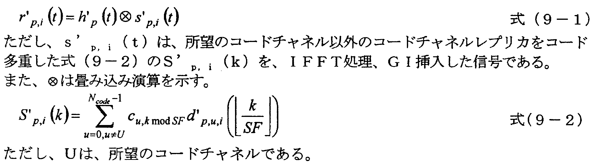
なお、本実施形態のデータ受信機装置200の信号検出部203は、受信信号毎信号検出部を複数具備し、信号検出と復号の繰り返しの各回の処理において、初送パケットまたは再送パケットの信号を含む複数の受信信号に対して並行して信号検出を行なっているが、信号検出部203が受信信号毎信号検出部を一つのみ具備するようにし、その受信信号毎信号検出部が、複数の受信信号対して順次信号検出を行うようにしてもよい。
このような第2フレーム受信時の信号処理の結果、パケット2~4の全てについて、誤り検出部242が誤りを検出しなかったとする。パケット受信装置200は、パケット2~4に対して各々、応答信号としてACK信号を送信装置100に向けて送信する(Sb4)。
また、本実施形態は、再送パケット受信時において、その再送パケット以前に受信したパケット信号データに対しても信号検出処理を行う通信装置として、干渉キャンセラを具備したパケット受信装置200を用いて説明したが、復号処理結果を用いた等化処理による信号検出と、該等化器の処理結果の復号処理とを繰り返すターボ等化器などのターボ概念を用いた繰り返し処理を行う通信装置であってもよい。
第2の実施形態では、ハイブリッド自動再送HARQを適用したパケット通信を行う通信システムにおいて、繰り返し処理用いた干渉キャンセラを具備した通信装置によりパケットを受信する場合、再送パケット信号受信時に、前記再送パケット以前に受信したパケット信号データに対しても干渉除去処理を行う干渉除去部を具備した第2の実施形態の通信装置を説明する。具体的には、本実施形態のパケット受信装置(第2の通信装置)200aは、再送パケット毎に干渉成分除去処理を行った信号を、復調処理を行う前に合成する構成を有し、特に、チェース合成CCを用いたハイブリッド自動再送HARQに適用される。
例えば、受信部202が第p回目のパケット信号を受信し、受信信号毎信号検出部207a-pが第p回目のパケット信号に対して第i回目の干渉除去処理を行う場合、同時に再度、既受信している第u回目(1≦u≦p-1)の受信パケット信号に対しても受信信号毎信号検出部207a-uが第i’回目(1≦i’≦i)回目の干渉除去処理を行う。
以降では、i’=iの場合で説明する。


なお、上記の干渉レプリカ生成部256aは、一例としてコード間干渉MCIを除去する場合の構成を示したが、キャリア間干渉ICI、シンボル間干渉ISIなど干渉レプリカを生成することで、各々の干渉成分を除去することが可能である。逆拡散部216aは、合成部204aからの出力信号に該当するコードチャネルの拡散符号を乗算して逆拡散を行う。復調部217、デインターリーブ部218、デパンクチャ部219は、第1の実施形態の図7に示す復調部217、デインターリーブ部218、デパンクチャ部219と同様の動作を行う。復号部205aは、デパンクチャ部219の出力信号に対して、第1の実施形態の図7に示す復号部205と同様の動作を行う。
第3の実施形態の通信システムでは、送信されたパケットは、MIMO(Multi Input Multi Output:マルチ入力マルチ出力)を用いて空間多重される。本実施形態における通信システムは、パケット送信装置(第1の通信装置)500とパケット受信装置(第2の通信装置)600とで構成され、パケット受信装置600は、繰り返し逐次型干渉キャンセラ(SIC)によって他ストリームの信号を除去し、再送パケット信号受信時には、この再送パケット以前に受信したパケット信号データに対しても他ストリームの信号の除去を、繰り返し逐次型干渉キャンセラによって行う。ここで、ストリームとは、各送信アンテナから送信される信号列を表す、すなわち、同じ送信アンテナから送信される信号は、同じストリームの信号であり、異なる送信アンテナから送信される信号は、異なるストリームの信号である。また、本実施形態では、パケットの伝送方式として、OFDM方式(Orthogonal Frequency Division Multiplexing:直交周波数分割多重)を適用した場合を説明する。

例えば、FFT612が第p回目の受信パケットに対する信号を出力し、受信信号毎信号検出部1601-1-p~1601-N-pが第p回目の受信パケット信号に対して第i回目の干渉除去処理を行う場合、同時に、既受信している第u回目(1≦u≦p-1)の受信パケット信号に対しても受信信号毎信号検出部1601-1-u~1601-N-uが第i’(1≦i’≦i)回目の干渉除去処理を行う。
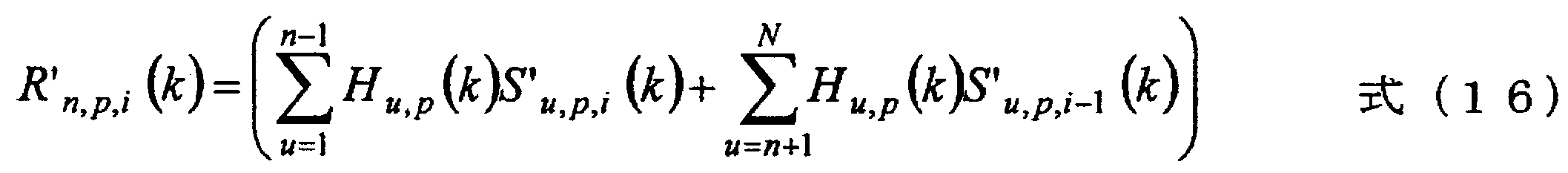
なお、i=1の場合(初回処理)、第i回目の繰り返し処理ですでに生成したストリーム1~ストリーム(n-1)のシンボルレプリカのみと伝搬路推定値から受信信号レプリカを生成する。
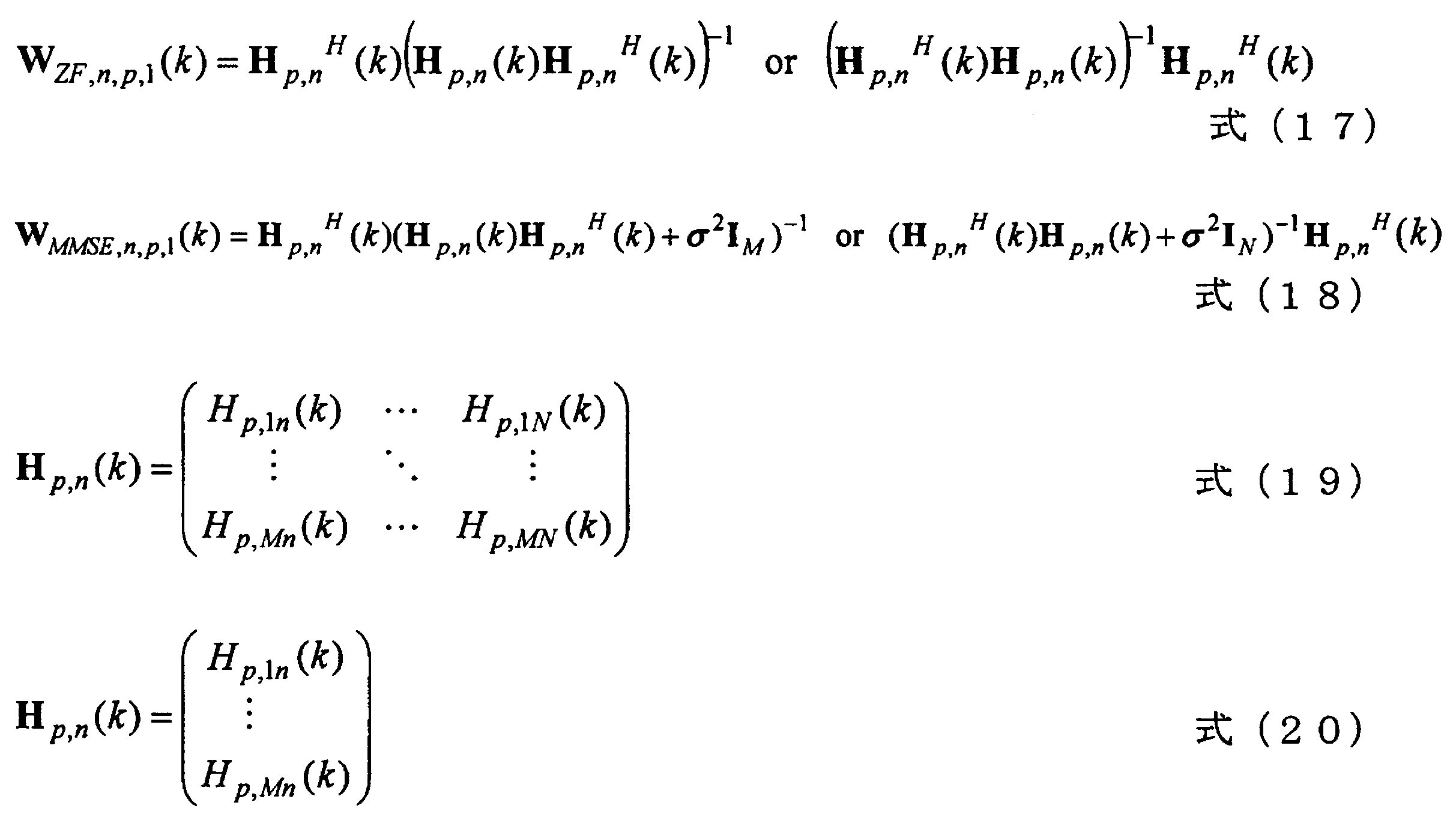
また、図7における受信部202、伝搬路推定部210、干渉除去部212、GI除去部213、FFT部214、伝搬路補償部215、逆拡散部216、復調部217、デインターリーブ部218、デパンクチャ部219、合成部204、復号部205、受信パケット管理部206、応答信号生成部220、および図15における受信部202、GI除去部213a、FFT部214、伝搬路推定部210a、干渉除去部212a、伝搬路補償部215a、合成部204a、逆拡散部216a、復調部217、デインターリーブ部218、デパンクチャ部219、復号部205a、および図18における受信部610、GI除去部611、FFT部612、伝搬路推定部613、受信パケット管理部603、受信信号処理部604、受信信号処理部602-1の機能を実現するためのプログラムをコンピュータ読み取り可能な記録媒体に記録して、この記録媒体に記録されたプログラムをコンピュータシステムに読み込ませ、実行することにより各部の処理を行ってもよい。なお、ここでいう「コンピュータシステム」とは、OSや周辺機器等のハードウェアを含むものとする。
Claims (11)
- 同一のデータに関する初送信号を含む信号と再送信号を含む信号とを受信する受信部と、
受信した前記信号から、同一のデータに関する前記初送信号および複数の前記再送信号のうち少なくとも2つの信号を、復号処理結果を用いて検出する信号検出部と、
前記信号検出部が検出した少なくとも2つの信号を合成する合成部と、
合成した前記信号を復号処理して前記復号処理結果を得る復号部と、
を具備し、
同一のデータに関する複数の前記信号について、前記信号検出部による検出と、前記合成部による合成と、前記復号部による復号処理とを、繰り返し行うこと
を特徴とする通信装置。 - 前記信号検出部が検出する少なくとも2つの信号は、前記初送信号を含むことを特徴とする請求項1の通信装置。
- 前記信号検出部は、前記受信部が受信した前記同一のデータに関する全ての前記初送信号および前記再送信号を検出し、
前記合成部は、前記信号検出部が検出した前記同一のデータに関する全ての前記信号同士を合成することを特徴とする請求項1に記載の通信装置。 - 前記信号検出部は、
前記復号処理結果に基づき、前記初送信号に対する干渉レプリカと前記再送信号に対する干渉レプリカを生成し、前記受信部が受信した前記信号から該干渉レプリカを減算すること、
を特徴とする請求項1に記載の通信装置。 - 前記復号処理部は、軟判定した復号処理結果を出力し、
前記信号検出部は、軟判定した前記復号処理結果を用いて前記干渉レプリカを生成すること、
を特徴とする請求項4に記載の通信装置。 - 前記干渉レプリカは、前記初送信号または前記再送信号に対するシンボル間干渉、キャリア干渉、符号間干渉、ストリーム間干渉のいずれかの干渉成分の干渉レプリカであることを特徴とする請求項4に記載の通信装置。
- 前記信号検出部は、前記受信部が受信した前記信号から前記干渉レプリカを減算した信号を復調して軟判定結果を出力し、
前記合成部は、前記軟判定結果を合成すること
を特徴とする請求項4に記載の通信装置。 - 前記受信部が受信する前記信号は空間多重された信号であり、
前記信号検出部は、前記受信部が受信した前記信号を構成するストリームの分離処理を行うMIMO分離部を備えること
を特徴とする請求項4に記載の通信装置。 - データに関する初送信号を送信し、該初送信号の応答として再送要求を通信相手の通信装置から受信すると、前記データに関する再送信号を送信する第1の通信装置と、該第1の通信装置が送信した信号を受信し、該信号を復号した結果に誤りを検出したときは、前記第1の通信装置に再送を要求する第2の通信装置とを具備する通信システムにおいて、
前記第2の通信装置は、
同一のデータに関する初送信号を含む信号と再送信号を含む信号とを受信する受信部と、
受信した前記信号から、同一のデータに関する前記初送信号および複数の前記再送信号のうち少なくとも2つの信号を、復号処理結果を用いて検出する信号検出部と、
前記信号検出部が検出した少なくとも2つの信号を合成する合成部と、
合成した前記信号を復号処理して前記復号処理結果を得る復号部と、
を具備し、
同一のデータに関する複数の前記信号について、前記信号検出部による検出と、前記合成部による合成と、前記復号部による復号処理とを、繰り返し行うこと
を特徴とする通信システム。 - 通信装置における受信方法において、
前記通信装置が、同一のデータに関する初送信号を含む信号と再送信号を含む信号とを受信する第1の過程と、
前記通信装置が、受信した前記信号から、同一のデータに関する前記初送信号および複数の前記再送信号のうち少なくとも2つの信号を、復号処理結果を用いて検出する第2の過程と、
前記通信装置が、前記第2の過程にて検出した少なくとも2つの信号を合成する第3の過程と、
前記通信装置が、前記第3の過程にて合成した前記信号を復号処理して前記復号処理結果を得る第4の過程と、
を有し、
同一のデータに関する複数の前記信号について、前記第2の過程と、前記第3の過程と、前記第4の過程とを、繰り返し行うこと
を特徴とする受信方法。 - 通信装置が具備するコンピュータを、
同一のデータに関する初送信号を含む信号と再送信号を含む信号とを受信する受信部、
受信した前記信号から、同一のデータに関する前記初送信号および複数の前記再送信号のうち少なくとも2つの信号を、復号処理結果を用いて検出する信号検出部、
前記信号検出部が検出した少なくとも2つの信号を合成する合成部、
合成した前記信号を復号処理して前記復号処理結果を得る復号部、
として機能させ、
同一のデータに関する複数の前記信号について、前記信号検出部による検出と、前記合成部による合成と、前記復号部による復号処理とを繰り返し行わせるプログラム。
Priority Applications (4)
| Application Number | Priority Date | Filing Date | Title |
|---|---|---|---|
| EP09713295A EP2247018A4 (en) | 2008-02-21 | 2009-02-20 | COMMUNICATION DEVICE, COMMUNICATION SYSTEM, RECEIVING METHOD AND PROGRAM |
| JP2009554407A JP5213271B2 (ja) | 2008-02-21 | 2009-02-20 | 通信装置、通信システム、受信方法およびプログラム |
| US12/918,243 US20110044409A1 (en) | 2008-02-21 | 2009-02-20 | Communication device, communication system, reception method, and program |
| CN2009801037316A CN101933277A (zh) | 2008-02-21 | 2009-02-20 | 通信装置、通信系统、接收方法和程序 |
Applications Claiming Priority (2)
| Application Number | Priority Date | Filing Date | Title |
|---|---|---|---|
| JP2008040009 | 2008-02-21 | ||
| JP2008-040009 | 2008-02-21 |
Publications (1)
| Publication Number | Publication Date |
|---|---|
| WO2009104764A1 true WO2009104764A1 (ja) | 2009-08-27 |
Family
ID=40985641
Family Applications (1)
| Application Number | Title | Priority Date | Filing Date |
|---|---|---|---|
| PCT/JP2009/053088 Ceased WO2009104764A1 (ja) | 2008-02-21 | 2009-02-20 | 通信装置、通信システム、受信方法およびプログラム |
Country Status (5)
| Country | Link |
|---|---|
| US (1) | US20110044409A1 (ja) |
| EP (1) | EP2247018A4 (ja) |
| JP (1) | JP5213271B2 (ja) |
| CN (1) | CN101933277A (ja) |
| WO (1) | WO2009104764A1 (ja) |
Cited By (3)
| Publication number | Priority date | Publication date | Assignee | Title |
|---|---|---|---|---|
| JP2011097125A (ja) * | 2009-10-27 | 2011-05-12 | Sharp Corp | 受信装置、受信方法、通信システムおよび通信方法 |
| JP2012044482A (ja) * | 2010-08-19 | 2012-03-01 | Fujitsu Ltd | 無線通信システム、受信局及び無線通信方法 |
| CN112822132A (zh) * | 2020-12-31 | 2021-05-18 | 华中科技大学 | 一种水声ofdm接收机中时频域联合抑制ici的方法和系统 |
Families Citing this family (30)
| Publication number | Priority date | Publication date | Assignee | Title |
|---|---|---|---|---|
| DE102005028447B4 (de) | 2005-06-17 | 2009-12-17 | Wobben, Aloys | Schiff |
| US8660217B2 (en) | 2010-11-05 | 2014-02-25 | Qualcomm Incorporated | Methods and apparatus for low complexity soft-input soft-output group detection |
| WO2012141227A1 (ja) * | 2011-04-11 | 2012-10-18 | Asahina Tadashi | 符号系列を用いた送信信号の生成検出方法、通信システム及び計測システム |
| US9106341B2 (en) | 2011-12-12 | 2015-08-11 | Intel Deutschland Gmbh | Communication terminal and method for receiving data |
| US9264180B2 (en) * | 2011-12-21 | 2016-02-16 | Telefonaktiebolaget L M Ericsson (Publ) | Method, network node, computer program and computer program product for decoding a signal |
| EP2798763B1 (en) * | 2011-12-28 | 2020-07-15 | Telefonaktiebolaget LM Ericsson (publ) | Symbol detection technique |
| CN103503072B (zh) * | 2012-04-04 | 2016-11-02 | 松下知识产权经营株式会社 | 解码装置以及解码方法 |
| US9590768B2 (en) | 2012-05-04 | 2017-03-07 | Telefonaktiebolaget Lm Ericsson (Publ) | Method, receiver device, network node and mobile communication terminal for decoding transmissions |
| GB2497149B (en) * | 2012-05-22 | 2013-11-20 | Aeroflex Ltd | A noise power estimation method |
| US9130749B1 (en) * | 2012-09-12 | 2015-09-08 | Marvell Internatonal Ltd. | Method and apparatus for decoding a data packet using scalable soft-bit retransmission combining |
| KR20160007644A (ko) * | 2013-05-16 | 2016-01-20 | 후아웨이 테크놀러지 컴퍼니 리미티드 | 데이터 송신 방법, 디바이스 및 시스템 |
| WO2016015213A1 (en) * | 2014-07-29 | 2016-02-04 | Panasonic Intellectual Property Corporation Of America | Conveying number of required harq repetitions for coverage enhancement |
| ES2912249T3 (es) | 2015-09-21 | 2022-05-25 | hyPHY USA Inc | Sistema para transportar señales muestreadas a través de rutas electromagnéticas imperfectas |
| US9794008B2 (en) * | 2015-12-04 | 2017-10-17 | Montage Technology (Shanghai) Co., Ltd. | Noise power estimator, receiver and method for noise power estimation |
| CN107302416A (zh) * | 2016-04-15 | 2017-10-27 | 索尼公司 | 用于无线通信系统的收发端的装置和方法、软信息估计器 |
| WO2018008084A1 (ja) * | 2016-07-05 | 2018-01-11 | 株式会社日立国際電気 | 無線通信システム、無線通信装置および無線通信方法 |
| CN113708882B (zh) | 2017-03-20 | 2024-03-29 | Hyphy美国有限公司 | 通过多个电磁路径传输采样信号 |
| US11271780B2 (en) * | 2020-07-01 | 2022-03-08 | Semiconductor Components Industries, Llc | Received signal equalization of wireless transmissions |
| US12431937B2 (en) * | 2020-09-23 | 2025-09-30 | Intel Corporation | Self-interference canceller |
| US11716114B2 (en) | 2020-11-25 | 2023-08-01 | Hyphy Usa Inc. | Encoder and decoder circuits for the transmission of video media using spread spectrum direct sequence modulation |
| FR3117300A1 (fr) * | 2020-12-03 | 2022-06-10 | Orange | Procédé de télécommunication pour réception itérative et dispositifs correspondant |
| US12335086B2 (en) | 2021-07-12 | 2025-06-17 | Hyphy Usa Inc. | Spread-spectrum video transport with quadrature amplitude modulation |
| EP4367876A4 (en) | 2021-08-12 | 2025-06-04 | HYPHY USA Inc. | DISTRIBUTION OF STEPPING SAMPLED SIGNALS AND TRANSMISSION VIA ELECTROMAGNETIC PATHWAYS |
| US11997415B2 (en) | 2021-08-17 | 2024-05-28 | Hyphy Usa Inc. | Sampled analog storage system |
| US12531007B2 (en) | 2023-02-21 | 2026-01-20 | Hyphy Usa Inc. | Analog video transport to a display panel and source driver integration with display panel |
| US12039951B2 (en) | 2021-09-03 | 2024-07-16 | Hyphy Usa Inc. | Spread-spectrum video transport integration with display drivers |
| US12148354B2 (en) | 2021-09-17 | 2024-11-19 | Hyphy Usa Inc. | Spread-spectrum video transport integration with virtual reality headset |
| US11769468B2 (en) | 2022-01-19 | 2023-09-26 | Hyphy Usa Inc. | Spread-spectrum video transport integration with timing controller |
| US11842671B2 (en) | 2022-03-07 | 2023-12-12 | Hyphy Usa Inc. | Spread-spectrum video transport source driver integration with display panel |
| CN119923854A (zh) | 2022-08-16 | 2025-05-02 | Hyphy美国有限公司 | 具有正交频分复用和ofdm视频传输的扩频视频传输 |
Citations (3)
| Publication number | Priority date | Publication date | Assignee | Title |
|---|---|---|---|---|
| JP2004221702A (ja) | 2003-01-10 | 2004-08-05 | Rikogaku Shinkokai | Ofdm(直交周波数分割多重)適応等化受信方式及び受信機 |
| JP2005198223A (ja) | 2004-01-07 | 2005-07-21 | Satoshi Suyama | マルチキャリアにおけるパケット伝送用マルチユーザ検出受信機 |
| JP2007184926A (ja) * | 2005-12-29 | 2007-07-19 | Ntt Docomo Inc | Arq機能を有する部分並列干渉キャンセル方法及び受信機 |
Family Cites Families (9)
| Publication number | Priority date | Publication date | Assignee | Title |
|---|---|---|---|---|
| DE60104113T2 (de) * | 2001-08-22 | 2004-10-28 | Matsushita Electric Industrial Co., Ltd., Kadoma | Übertragungsverfahren und Übertragungsgerät mit Mehrkanal-ARQ |
| EP1518326B1 (en) * | 2002-07-01 | 2007-11-14 | Telefonaktiebolaget LM Ericsson (publ) | Method for iterative decoder scheduling |
| KR100689382B1 (ko) * | 2003-06-20 | 2007-03-02 | 삼성전자주식회사 | 직교분할다중화방식을 기반으로 하는이동통신시스템에서의 송신장치 및 방법 |
| US20050022101A1 (en) * | 2003-07-21 | 2005-01-27 | Peter Malm | Fast iteration termination of Turbo decoding |
| KR20050046471A (ko) * | 2003-11-14 | 2005-05-18 | 삼성전자주식회사 | 저밀도 패러티 검사 부호를 병렬 연접하는 채널부호화/복호화 장치 및 방법 |
| US7984365B2 (en) * | 2004-12-02 | 2011-07-19 | St-Ericsson Sa | Turbo decoder with stake heritage for data block redundant version decoding |
| KR100656982B1 (ko) * | 2004-12-21 | 2006-12-13 | 한국전자통신연구원 | 휴대 인터넷 단말기의 복호 장치 및 방법 |
| JP2007116637A (ja) * | 2005-10-24 | 2007-05-10 | Fujitsu Ltd | 無線通信方法及び無線通信システム並びに受信装置及び送信装置 |
| KR100966043B1 (ko) * | 2005-10-31 | 2010-06-25 | 삼성전자주식회사 | 저밀도 패리티 검사 부호를 사용하는 통신 시스템에서 신호 송수신 장치 및 방법 |
-
2009
- 2009-02-20 JP JP2009554407A patent/JP5213271B2/ja not_active Expired - Fee Related
- 2009-02-20 WO PCT/JP2009/053088 patent/WO2009104764A1/ja not_active Ceased
- 2009-02-20 EP EP09713295A patent/EP2247018A4/en not_active Withdrawn
- 2009-02-20 CN CN2009801037316A patent/CN101933277A/zh active Pending
- 2009-02-20 US US12/918,243 patent/US20110044409A1/en not_active Abandoned
Patent Citations (3)
| Publication number | Priority date | Publication date | Assignee | Title |
|---|---|---|---|---|
| JP2004221702A (ja) | 2003-01-10 | 2004-08-05 | Rikogaku Shinkokai | Ofdm(直交周波数分割多重)適応等化受信方式及び受信機 |
| JP2005198223A (ja) | 2004-01-07 | 2005-07-21 | Satoshi Suyama | マルチキャリアにおけるパケット伝送用マルチユーザ検出受信機 |
| JP2007184926A (ja) * | 2005-12-29 | 2007-07-19 | Ntt Docomo Inc | Arq機能を有する部分並列干渉キャンセル方法及び受信機 |
Non-Patent Citations (8)
| Title |
|---|
| D. CHASE: "code combining-A maximum likelihood decoding approach for combining and arbitrary number of noisy packets", IEEE TRANS. COMMUN., vol. COM-33, May 1985 (1985-05-01), pages 385 - 393 |
| HAITAO ZHENG ET AL.: "Multiple ARQ Processes for MIMO Systems", EURASIP JOURNAL ON APPLIED SIGNAL PROCESSING, vol. 2004, no. ISSUE, 2004, pages 2004 * |
| J. HAGENAUER: "Rate-compatible punctured convolutional codes (RCPC codes) and their application", IEEE TRANS. COMMUN., vol. 36, April 1988 (1988-04-01), pages 389 - 400 |
| KOIICHI ADACHI ET AL.: "Kurikaeshi Henkei QRD-M Shingo Bunriho o Mochiiru OFDM MIMO no HARQ Throughput Tokusei", IEICE TECHNICAL REPORT, RCS 107(147), THE INSTITUTE OF ELECTRONICS, INFORMATION AND COMMUNICATION ENGINEERS, vol. 07, 2007, pages 47 - 52, XP008139558 * |
| See also references of EP2247018A4 |
| T. YOSHIMOTO, R. YAMADA , K, SHIMEZAWA: "Proc. IEEE VTC", 2007, SPRING, article "Performance of MC-CDM Systems with Inter-Code Interference Canceller and Frequency-Domain Interleaver" |
| TATSUNORI YUI ET AL.: "ICI Canceller o Mochiiru Turbo Fugoka MC-CDMA ni Okeru Hantei Kikan Channel Suitei", IEICE TECHNICAL REPORT, RCS 107 (262), THE INSTITUTE OF ELECTRONICS, INFORMATION AND COMMUNICATION ENGINEERS, 11 October 2007 (2007-10-11), pages 7 - 12, XP008139557 * |
| Y. ZHOU; J. WANG; M. SAWAHASHI: "Downlink Transmission of Broadband OFCDM Systems-Part III: Turbo-Coded", IEEE JSAC, vol. 24, no. 1, pages 132 - 140 |
Cited By (4)
| Publication number | Priority date | Publication date | Assignee | Title |
|---|---|---|---|---|
| JP2011097125A (ja) * | 2009-10-27 | 2011-05-12 | Sharp Corp | 受信装置、受信方法、通信システムおよび通信方法 |
| JP2012044482A (ja) * | 2010-08-19 | 2012-03-01 | Fujitsu Ltd | 無線通信システム、受信局及び無線通信方法 |
| CN112822132A (zh) * | 2020-12-31 | 2021-05-18 | 华中科技大学 | 一种水声ofdm接收机中时频域联合抑制ici的方法和系统 |
| CN112822132B (zh) * | 2020-12-31 | 2022-02-15 | 华中科技大学 | 一种水声ofdm接收机中时频域联合抑制ici的方法和系统 |
Also Published As
| Publication number | Publication date |
|---|---|
| EP2247018A1 (en) | 2010-11-03 |
| JPWO2009104764A1 (ja) | 2011-06-23 |
| US20110044409A1 (en) | 2011-02-24 |
| JP5213271B2 (ja) | 2013-06-19 |
| EP2247018A4 (en) | 2011-02-23 |
| CN101933277A (zh) | 2010-12-29 |
Similar Documents
| Publication | Publication Date | Title |
|---|---|---|
| JP5213271B2 (ja) | 通信装置、通信システム、受信方法およびプログラム | |
| JP5376243B2 (ja) | 通信装置、通信システム、受信方法および通信方法 | |
| US8381060B2 (en) | Communication device, communication system, reception method, and communication method | |
| US20110126072A1 (en) | Communication device, communication system, reception method and communication method | |
| US20110041023A1 (en) | Communication device, communication system, reception method, and program | |
| US20110007729A1 (en) | Reception device, transmission device, communication system, and communication method | |
| JP5013617B2 (ja) | 通信装置、通信システムおよび受信方法 | |
| US20100325510A1 (en) | Transmission device, reception device, communication system, and communication method | |
| JP5376244B2 (ja) | 通信装置、通信システム、受信方法及び通信方法 | |
| JP5679771B2 (ja) | 無線通信装置及び無線通信方法 | |
| EP1724959B1 (en) | Multiple access communication system with ARQ and interference cancellation | |
| JP5036062B2 (ja) | 通信装置、通信システムおよび通信方法 | |
| JP4631053B2 (ja) | 再送装置及び再送方法 | |
| JP2010050716A (ja) | 通信装置、通信システム及び通信方法 |
Legal Events
| Date | Code | Title | Description |
|---|---|---|---|
| WWE | Wipo information: entry into national phase |
Ref document number: 200980103731.6 Country of ref document: CN |
|
| 121 | Ep: the epo has been informed by wipo that ep was designated in this application |
Ref document number: 09713295 Country of ref document: EP Kind code of ref document: A1 |
|
| ENP | Entry into the national phase |
Ref document number: 2009554407 Country of ref document: JP Kind code of ref document: A |
|
| WWE | Wipo information: entry into national phase |
Ref document number: 12918243 Country of ref document: US |
|
| NENP | Non-entry into the national phase |
Ref country code: DE |
|
| WWE | Wipo information: entry into national phase |
Ref document number: 2009713295 Country of ref document: EP |