WO2009107296A1 - ターボ冷凍機および冷凍システムならびにこれらの制御方法 - Google Patents
ターボ冷凍機および冷凍システムならびにこれらの制御方法 Download PDFInfo
- Publication number
- WO2009107296A1 WO2009107296A1 PCT/JP2008/071402 JP2008071402W WO2009107296A1 WO 2009107296 A1 WO2009107296 A1 WO 2009107296A1 JP 2008071402 W JP2008071402 W JP 2008071402W WO 2009107296 A1 WO2009107296 A1 WO 2009107296A1
- Authority
- WO
- WIPO (PCT)
- Prior art keywords
- cold water
- turbo
- target
- flow rate
- control unit
- Prior art date
- Legal status (The legal status is an assumption and is not a legal conclusion. Google has not performed a legal analysis and makes no representation as to the accuracy of the status listed.)
- Ceased
Links
Images


Classifications
-
- F—MECHANICAL ENGINEERING; LIGHTING; HEATING; WEAPONS; BLASTING
- F25—REFRIGERATION OR COOLING; COMBINED HEATING AND REFRIGERATION SYSTEMS; HEAT PUMP SYSTEMS; MANUFACTURE OR STORAGE OF ICE; LIQUEFACTION SOLIDIFICATION OF GASES
- F25B—REFRIGERATION MACHINES, PLANTS OR SYSTEMS; COMBINED HEATING AND REFRIGERATION SYSTEMS; HEAT PUMP SYSTEMS
- F25B49/00—Arrangement or mounting of control or safety devices
- F25B49/02—Arrangement or mounting of control or safety devices for compression type machines, plants or systems
-
- F—MECHANICAL ENGINEERING; LIGHTING; HEATING; WEAPONS; BLASTING
- F25—REFRIGERATION OR COOLING; COMBINED HEATING AND REFRIGERATION SYSTEMS; HEAT PUMP SYSTEMS; MANUFACTURE OR STORAGE OF ICE; LIQUEFACTION SOLIDIFICATION OF GASES
- F25D—REFRIGERATORS; COLD ROOMS; ICE-BOXES; COOLING OR FREEZING APPARATUS NOT OTHERWISE PROVIDED FOR
- F25D17/00—Arrangements for circulating cooling fluids; Arrangements for circulating gas, e.g. air, within refrigerated spaces
- F25D17/02—Arrangements for circulating cooling fluids; Arrangements for circulating gas, e.g. air, within refrigerated spaces for circulating liquids, e.g. brine
-
- F—MECHANICAL ENGINEERING; LIGHTING; HEATING; WEAPONS; BLASTING
- F25—REFRIGERATION OR COOLING; COMBINED HEATING AND REFRIGERATION SYSTEMS; HEAT PUMP SYSTEMS; MANUFACTURE OR STORAGE OF ICE; LIQUEFACTION SOLIDIFICATION OF GASES
- F25B—REFRIGERATION MACHINES, PLANTS OR SYSTEMS; COMBINED HEATING AND REFRIGERATION SYSTEMS; HEAT PUMP SYSTEMS
- F25B1/00—Compression machines, plants or systems with non-reversible cycle
- F25B1/04—Compression machines, plants or systems with non-reversible cycle with compressor of rotary type
- F25B1/053—Compression machines, plants or systems with non-reversible cycle with compressor of rotary type of turbine type
-
- F—MECHANICAL ENGINEERING; LIGHTING; HEATING; WEAPONS; BLASTING
- F25—REFRIGERATION OR COOLING; COMBINED HEATING AND REFRIGERATION SYSTEMS; HEAT PUMP SYSTEMS; MANUFACTURE OR STORAGE OF ICE; LIQUEFACTION SOLIDIFICATION OF GASES
- F25B—REFRIGERATION MACHINES, PLANTS OR SYSTEMS; COMBINED HEATING AND REFRIGERATION SYSTEMS; HEAT PUMP SYSTEMS
- F25B2400/00—General features or devices for refrigeration machines, plants or systems, combined heating and refrigeration systems or heat-pump systems, i.e. not limited to a particular subgroup of F25B
- F25B2400/06—Several compression cycles arranged in parallel
-
- F—MECHANICAL ENGINEERING; LIGHTING; HEATING; WEAPONS; BLASTING
- F25—REFRIGERATION OR COOLING; COMBINED HEATING AND REFRIGERATION SYSTEMS; HEAT PUMP SYSTEMS; MANUFACTURE OR STORAGE OF ICE; LIQUEFACTION SOLIDIFICATION OF GASES
- F25B—REFRIGERATION MACHINES, PLANTS OR SYSTEMS; COMBINED HEATING AND REFRIGERATION SYSTEMS; HEAT PUMP SYSTEMS
- F25B2700/00—Sensing or detecting of parameters; Sensors therefor
- F25B2700/21—Temperatures
- F25B2700/2117—Temperatures of an evaporator
- F25B2700/21171—Temperatures of an evaporator of the fluid cooled by the evaporator
- F25B2700/21172—Temperatures of an evaporator of the fluid cooled by the evaporator at the inlet
Definitions
- the present invention relates to a turbo refrigerator, a refrigeration system, and control methods thereof.
- the operation can be continued at a low heat load, there is a demand to operate at a low heat load after controlling the required temperature on the external load side.
- the cold water required by the external load is required for the turbo chillers to be installed before the start of operation. It is preferable to stand by while operating at a low load while maintaining the temperature, that is, to satisfy the required cold water temperature.
- Such operation is also required for a turbo chiller that is going to stop operation when the target heat load decreases and the number of turbo chillers operating is reduced.
- the present invention has been made in view of such circumstances, and provides a turbo chiller and a refrigeration system that enable temperature adjustment even when the target heat load is low, and a control method thereof. With the goal.
- the turbo chiller and the refrigeration system and the control method thereof according to the present invention employ the following means. That is, the first aspect of the turbo refrigerator according to the present invention is expanded by a turbo compressor that compresses a refrigerant, a condenser that condenses the compressed refrigerant, an expansion valve that expands the condensed refrigerant, and the like. An evaporator that evaporates the refrigerant and cools the cold water, and a refrigerator-side control unit that controls the operation so that the cold water outlet temperature, which is the temperature of the cold water cooled by the evaporator, becomes a desired value.
- the refrigerator-side control unit is provided with a target heat load from an output destination of the cold water, and the refrigerator-side control unit is configured to output the evaporator when the target heat load is a predetermined value or less.
- the target chilled water flow rate that satisfies the target heat load is output based on the current chilled water inlet temperature that is the current temperature of the chilled water flowing into the chilled water and the target chilled water outlet temperature that is the target chilled water outlet temperature. .
- the load (output) of the turbo refrigerator is proportional to the temperature difference between the cold water inlet temperature and the cold water outlet temperature, and the cold water flow rate. Therefore, when the target heat load is a predetermined value or less (for example, 20% or less, preferably 10% or less), there is a limit to lowering the heat load of the turbo refrigerator as long as the chilled water flow rate is set to the rated flow rate. If the target cold water outlet temperature is not particularly set and the operation does not simply generate a heat load, the operation may be performed based on the invention described in Japanese Patent Application No. 2007-166843 filed earlier by the present inventors. On the other hand, there is a problem when the target cold water outlet temperature is set and the applied target heat load is small.
- the refrigerator-side control unit outputs a target chilled water flow rate that satisfies the target heat load based on the current value chilled water inlet temperature and the target chilled water outlet temperature. If chilled water is supplied to the turbo chiller based on the target chilled water flow rate, a temperature adjustment operation capable of controlling the temperature to the target chilled water outlet temperature is realized even when the target heat load is low.
- the refrigerator-side control unit obtains a current value cold water flow rate that is a current cold water flow rate, and the current value cold water flow rate is equal to or less than a predetermined value below the target cold water flow rate. When it becomes, it is good also as performing the operation
- the operation of the centrifugal chiller is stopped when the current value cold water flow rate is equal to or less than a predetermined value lower than the target cold water flow rate.
- the flow rate is extremely low, such as 2% of the rated flow rate, the equipment is protected by always stopping.
- the refrigerator-side control unit obtains the evaporation pressure in the evaporator, and when the evaporation pressure becomes a predetermined value or less, the turbo refrigerator It is good also as performing the operation
- the centrifugal chiller continues to output the refrigeration load. Therefore, if the flow of chilled water stops for some reason, the chilled water in the heat transfer tube of the evaporator may be frozen. Therefore, in the above aspect, by obtaining the evaporation pressure in the evaporator and grasping the state of the cold water flowing in the heat transfer tube, it is determined that the cold water may freeze if the evaporation pressure is a predetermined value or less. Then, the operation of the turbo refrigerator was stopped. This control using the evaporation pressure may be combined with the above-described current value cold water flow rate, or may be used alone. Furthermore, the liquid refrigerant temperature of the evaporator or the current cold water outlet temperature may be used as a backup.
- the sensitivity of the feedback control output given to the temperature adjusting unit that controls the temperature of the cold water may be reduced according to the decrease in the current value cold water flow rate.
- the control gain of feedback control (for example, PID control or PI control) to be given to the temperature adjusting unit is usually determined based on the case where the chilled water flow rate is rated.
- the control gain at the rated time may cause excessive sensitivity and overshoot the chilled water temperature. So, in the said aspect, controllability is ensured by reducing the sensitivity of a feedback control output according to the fall of the present value cold water flow rate.
- the proportional gain is inversely proportional to the chilled water flow rate.
- the integration time of the integral gain may be made inversely proportional to the cold water flow rate.
- the “temperature adjusting unit” include an inlet vane (an inlet guide vane for capacity control) that adjusts the amount of refrigerant gas sucked provided in the refrigerant gas suction port of the turbo compressor.
- the second aspect of the refrigeration system of the present invention controls a plurality of turbo chillers, a chilled water supply unit that supplies chilled water supplied from these turbo chillers to an external load, and the flow rate and temperature of the chilled water.
- a refrigeration system including an equipment-side control unit, at least one of the plurality of turbo chillers is the turbo chiller described above, and the chiller-side control unit of the turbo chiller includes the equipment The target chilled water outlet temperature and the target heat load are obtained from the side control unit, and the target chilled water flow rate is output to the facility side control unit.
- the chilled water temperature and the chilled water flow rate are controlled by an equipment side control unit that controls the entire operation of the refrigeration system. Furthermore, the facility-side control unit can grasp the allowable target heat load even if the load is low. So, in the said 2nd aspect, it decided to pass target chilled water exit temperature and target heat load to the refrigerator side control part from the equipment side control part. And in the equipment side control part, the target cold-water flow rate output from the refrigerator side control part of a turbo refrigerator can be obtained. As a result, a refrigeration system capable of temperature adjustment operation even at a low target heat load is realized.
- a third aspect of the turbo chiller control method of the present invention includes a turbo compressor that compresses a refrigerant, a condenser that condenses the compressed refrigerant, an expansion valve that expands the condensed refrigerant, and an expansion An evaporator that evaporates the cooled refrigerant and cools the cold water, and a refrigerator-side control unit that controls the operation so that the cold water outlet temperature, which is the temperature of the cold water cooled by the evaporator, becomes a desired value.
- the refrigerator-side control unit is provided with a target heat load obtained from an output destination of the cold water, and the refrigerator-side control unit has the target heat load of a predetermined value or less.
- the chilled water that satisfies the target heat load based on the current value chilled water inlet temperature that is the current temperature of the chilled water that flows into the evaporator and the target chilled water outlet temperature that is the target chilled water outlet temperature.
- the target cold water flow rate is output.
- the load (output) of the turbo refrigerator is proportional to the temperature difference between the cold water inlet temperature and the cold water outlet temperature, and the cold water flow rate. Therefore, when the target heat load is a predetermined value or less (for example, 20% or less, preferably 10% or less), there is a limit to lowering the heat load of the turbo refrigerator as long as the chilled water flow rate is set to the rated flow rate. If the target cold water outlet temperature is not particularly set and the operation does not simply generate a heat load, the operation may be performed based on the invention described in Japanese Patent Application No. 2007-166843 filed earlier by the present inventors. On the other hand, there is a problem when the target cold water outlet temperature is set and the applied target heat load is small.
- the refrigerator-side control unit outputs a target chilled water flow rate that satisfies the target heat load based on the current value chilled water inlet temperature and the target chilled water outlet temperature. If chilled water is supplied to the turbo chiller based on the target chilled water flow rate, a temperature adjustment operation capable of controlling the temperature to the target chilled water outlet temperature is realized even when the target heat load is low.
- the fourth aspect of the control method of the refrigeration system of the present invention includes a plurality of turbo chillers, a chilled water supply unit that supplies chilled water supplied from these turbo chillers to an external load, and the flow rate and temperature of the chilled water.
- the turbo chiller described in any of the above is provided, and the chiller side of the turbo chiller is The control unit obtains the target chilled water outlet temperature and the target heat load from the facility-side control unit, and outputs the target chilled water flow rate to the facility-side control unit.
- the chilled water temperature and the chilled water flow rate are controlled by an equipment side control unit that controls the entire operation of the refrigeration system. Furthermore, the facility-side control unit can grasp the allowable target heat load even if the load is low. So, in the said 4th aspect, it decided to pass target chilled water exit temperature and target heat load to a refrigerator side control part from the equipment side control part. And in the equipment side control part, the target cold-water flow rate output from the refrigerator side control part of a turbo refrigerator can be obtained. As a result, a refrigeration system capable of temperature adjustment operation even at a low target heat load is realized.
- the refrigerator-side control unit outputs the target chilled water flow rate that satisfies the target heat load based on the current value chilled water inlet temperature and the target chilled water outlet temperature, and the turbo is generated based on the target chilled water flow rate. Since the cold water outlet temperature adjustment operation of the refrigerator is performed, a turbo refrigerator and a refrigeration system that can adjust the temperature and a control method thereof can be realized even when the target heat load is particularly low.
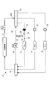
- FIG. 1 is a schematic configuration diagram showing a refrigeration system according to an embodiment of the present invention. It is the figure which showed transmission / reception of the equipment side control part and the refrigerator side control part. It is the graph which showed the threshold value of the cold water flow volume used when stopping the turbo refrigerator concerning one Embodiment of this invention.
- FIG. 1 shows an overall configuration of a refrigeration system according to an embodiment.
- the refrigeration system 1 is installed in a building or factory facility.
- the refrigeration system 1 includes three first to third turbo chillers 11, 12, and 13 that give cold heat to cold water supplied to an external load 3 such as an air conditioner or a fan coil. These first to third turbo refrigerators 11, 12, and 13 are installed in parallel to the external load 3.
- the turbo refrigerators 11, 12, and 13 are a turbo compressor that compresses a refrigerant, a condenser that condenses the high-temperature and high-pressure gas refrigerant compressed by the turbo compressor, and a high-temperature and high-pressure liquid refrigerant that is condensed by the condenser.
- An expansion valve for expanding and an evaporator for evaporating the liquid refrigerant expanded by the expansion valve are provided.
- the turbo compressor is a centrifugal compressor and is driven under the rotational speed control by an inverter drive motor.
- An inlet guide vane (inlet vane, hereinafter referred to as “IGV”) for controlling the flow rate of the intake refrigerant is provided at the refrigerant intake port of the turbo compressor.
- the cold water temperature is adjusted by adjusting the opening degree of the IGV.
- the IGV opening and the rotation speed of the turbo compressor are controlled by the refrigerator side control unit.
- Cold water having a rated temperature (for example, 7 ° C.) is obtained by absorbing heat in the evaporator. That is, the cold water flowing in the heat transfer tube inserted into the evaporator is cooled by removing heat from the refrigerant.
- This chilled water flow rate is controlled by chilled water pumps 21, 22, and 23, which will be described later.
- First to third chilled water pumps 21, 22, and 23 for pumping chilled water are installed on the upstream side of each of the centrifugal chillers 11, 12, and 13 as viewed from the chilled water flow.
- the cold water from the return header 32 is sent to the turbo refrigerators 11, 12, and 13 by these cold water pumps 21, 22, and 23.
- Each of the chilled water pumps 21, 22, and 23 is driven by an inverter motor, and thereby the variable flow rate is controlled by changing the rotation speed.
- the chilled water pump it is set as the structure provided with two or more with respect to each refrigerator, and you may make it perform variable flow control not only by rotation speed variable but by number control. Control of the chilled water pumps 21, 22, and 23 is performed by an equipment-side control unit that controls the entire refrigeration system 1.
- cold water obtained in each of the turbo chillers 11, 12, and 13 is collected.
- the cold water collected in the supply header 31 is supplied to the external load 3.
- the cold water that has been subjected to air conditioning or the like by the external load 3 and raised in temperature is sent to the return header 32.
- the cold water is branched at the return header 32 and sent to the turbo chillers 11, 12, and 13.
- a bypass circuit 33 is provided between the supply header 31 and the return header 32.
- the bypass circuit 33 is provided with an open / close valve 34.
- the opening / closing valve 34 is controlled by the equipment side controller.
- a first cold water flow meter 24 for measuring the flow rate flowing out of the first cold water pump 21 is provided on the downstream side of the first cold water pump 21.
- the output of the first cold water flow meter 24 is sent to the equipment-side control unit.
- a first bypass passage 25 that branches from between the first cold water pump 21 and the first turbo refrigerator 11 and is connected to the bypass circuit 33 is provided.
- the first bypass flow path 25 is provided with a first bypass flow meter 26 for measuring the cold water flow rate and a first bypass valve 27.
- the output of the first bypass flow meter is sent to the facility side control unit 40 (see FIG. 2).
- the opening degree of the first bypass valve 27 is controlled by the equipment-side control unit.
- a chilled water pipe upstream of the first turbo chiller 11 is provided with a first chilled water inlet temperature sensor 29 for measuring the temperature of the chilled water flowing into the first turbo chiller 11.
- the output of the first cold water inlet temperature sensor 29 is sent to the equipment side control unit 40.
- a chilled water pipe upstream of the return header 32 is provided with a temperature sensor 29 b for detecting the temperature of the chilled water returned from the external load 3.
- the second turbo chiller 12 and the third turbo chiller 13 are also provided with a bypass flow path, a bypass flow meter, a bypass valve, and a cold water inlet temperature sensor.
- these configurations are shown only for the first turbo refrigerator 11 for easy understanding. Of course, it is good also as a structure which does not provide these apparatuses in the 2nd turbo refrigerator 12 or the 3rd turbo refrigerator 13 according to a use.
- FIG. 2 shows data exchange between the equipment side control unit 40 and the refrigerator side control unit 42.
- the target heat load means a heat load that can be tolerated to the extent that the temperature of the chilled water that merges at the supply header 31 is not affected. That is, the supply header 31 where the chilled water supplied from other turbo chillers joins while satisfying the chilled water outlet temperature (target chilled water outlet temperature) required by the turbo chiller to be added when adding stages. It means a heat load that does not affect the chilled water temperature.
- the target chilled water outlet temperature depends on the chilled water temperature required by the external load 3, and is determined by the facility-side control unit.
- the current value cold water inlet temperature means the current cold water inlet temperature, and is obtained from the first cold water inlet temperature sensor 29 by the equipment side control unit 40 at a predetermined cycle.
- the refrigerator-side control unit 42 calculates a target chilled water flow rate that satisfies the target thermal load based on the target chilled water outlet temperature and the current value chilled water inlet temperature, and outputs the target chilled water flow rate to the facility-side control unit 42. That is, as shown in the following equation, the heat load Q output from the refrigerator is a target cold water flow rate using a relationship of a thermal balance that is proportional to the temperature difference between the cold water outlet temperature To and the cold water inlet temperature Ti and the cold water flow rate G. Is calculated.
- ⁇ means the specific gravity of the cold water at the average temperature of the cold water inlet / outlet
- ⁇ means the specific heat of the cold water at the average temperature of the cold water inlet / outlet.
- the facility-side control unit 40 controls the first cold water pump 21 and the first bypass valve 27 so that the target cold water flow rate obtained from the refrigerator-side control unit 42 is obtained.
- the output values of the first cold water flow meter 24 and the first bypass flow meter 26 are fed back.
- the flow rate control is difficult only by the rotational speed control of the chilled water pump 21, so the opening degree of the first bypass valve 27 is adjusted.
- the chilled water flow rate supplied to the first turbo chiller 11 can be obtained from the difference between the output value of the first chilled water flow meter 24 and the output value of the first bypass flow meter 26.
- the facility-side control unit 40 The first turbo chiller 11 enters the standby mode for early startup so that the thermal load can be output immediately if the startup command is issued.
- this early start standby mode cold water having a target cold water outlet temperature is supplied, while standby operation is performed while outputting a small heat load that does not affect the external load.
- the heat load at this time is an extremely low load, for example, 20% or less of the rating, preferably 10% or less of the rating.
- the refrigerator side control unit 42 obtains the target cold water outlet temperature, the current value cold water inlet temperature, and the target heat load from the facility side control unit 40. And the refrigerator side control part 42 calculates the target cold water flow volume of the cold water which satisfies target heat load based on these target cold water outlet temperature and present value cold water inlet temperature. That is, a ratio to the chilled water inlet / outlet temperature difference at the rated time is obtained based on the temperature difference between the target chilled water outlet temperature and the current value chilled water inlet temperature. This ratio becomes the refrigerator heat load at the rated cold water flow rate.
- the target cold water flow rate obtained in this way is output from the refrigerator side control unit 42 to the facility side control unit 42.
- the facility-side control unit 42 performs feedback control on the first cold water pump 21 and the first bypass valve 27 so as to realize the target cold water flow rate.
- the first turbo refrigerator 11 is operated to prepare for a future rapid load increase. For example, when rain passes and a sudden load increase is requested from the equipment-side control unit 40 for dehumidification, the first turbo chiller 11 has already been adjusted to the target cold water outlet temperature, so the load is quickly applied. Can be raised.
- the flow rate of chilled water is extremely small (for example, 3.3% of the rating in the above example), and the centrifugal chiller outputs a refrigeration output corresponding to the target heat load.
- Cold water may freeze in the heat pipe. Therefore, it is preferable to control as follows.
- the refrigerator side control unit 42 obtains the current cold water flow rate (current value cold water flow rate) from the facility side control unit 40. Then, when the current value cold water flow rate falls below the threshold obtained from the target cold water flow rate, it is determined that the cold water may stop and freeze in the heat transfer tube, and the turbo chiller is stopped.
- the threshold value is set as shown in FIG.
- the horizontal axis represents the target chilled water flow rate, expressed as a percentage of the rated chilled water flow rate.
- the vertical axis represents the threshold value of the cold water flow rate at which the turbo chiller is stopped.
- 60% of the target cold water flow rate is set as a threshold value. Therefore, when the flow rate is 30%, 18% of 60% is the threshold value.
- the threshold value should not be less than 2%. In this way, the device is protected by providing a threshold value that is an absolute lower limit.
- the refrigerator control unit 42 may obtain the evaporation pressure in the evaporator, and when the evaporation pressure becomes a predetermined value or less, the operation of stopping the turbo refrigerator may be started.
- the evaporation pressure becomes a predetermined value or less, it means that the evaporation temperature has dropped to a predetermined value or less, so that it is possible to accurately predict the freezing of the cold water in the heat transfer tube.
- the control based on the evaporation pressure is preferably used together with the control based on the cold water flow rate described above. Specifically, when either the cold water flow rate or the evaporation pressure falls below a predetermined value, the turbo chiller is stopped.
- the stop operation can be reliably performed.
- the output from the flow meter is obtained from the equipment-side control unit 40 from the refrigerator-side control unit 42, but if the evaporation pressure is used, the refrigerator-control unit 42 regardless of the equipment-side control unit 40. This has the advantage that the process can be completed. Further, in an environment where the cold water flow rate cannot be obtained from the facility-side control unit 40, it is possible to perform control related to the stop operation only by the evaporation pressure. Further, the liquid refrigerant temperature of the evaporator or the current cold water outlet temperature may be used for backup of sensor failure or the like.
- the temperature adjustment control of the turbo chiller is also preferably performed as follows.
- the temperature control of the cold water is performed by changing the opening of the IGV.
- This IGV opening is given by feedback control (for example, PID control or PI control) of the current cold water outlet temperature.
- the sensitivity of the control output at the time of this feedback control is reduced according to the decrease in the current value cold water flow rate.
- the control gain for obtaining the IGV opening is set based on the case where the chilled water flow rate is rated.
- the chilled water flow rate is significantly smaller than the rated value, so if the control gain at the rated time is used, the sensitivity may become excessive and overshoot may occur. Therefore, controllability is ensured by reducing the sensitivity of the feedback control output when obtaining the IGV opening according to the decrease in the current value cold water flow rate.
- the proportional gain is inversely proportional to the chilled water flow rate.
- the integration time of the integral gain may be made inversely proportional to the cold water flow rate.
- this embodiment demonstrated the operation
- this invention can be used also at the time of the stage reduction which reduces the number of turbo refrigerators. That is, when the thermal load required from the external load 3 decreases and one turbo chiller is stepped down, the turbo chiller is not stopped but is operated in the standby mode for early start-up described above. To continue. As a result, when the load increases again, it is possible to respond immediately.
- the number of stages of the turbo refrigerator is not limited to the three stages of the present embodiment, and may be two stages or four or more stages. Further, the number of turbo chillers capable of the above-described standby mode for early start-up may be only one, or some of the plurality of turbo chillers may be used. There may be.
Landscapes
- Engineering & Computer Science (AREA)
- Physics & Mathematics (AREA)
- Mechanical Engineering (AREA)
- Thermal Sciences (AREA)
- General Engineering & Computer Science (AREA)
- Chemical & Material Sciences (AREA)
- Combustion & Propulsion (AREA)
- Air Conditioning Control Device (AREA)
- Other Air-Conditioning Systems (AREA)
- Devices That Are Associated With Refrigeration Equipment (AREA)
Abstract
目標熱負荷が低い場合であっても、温度調節を可能とするターボ冷凍機を提供する。ターボ冷凍機(11)は、冷水出口温度を所望値となるように運転を制御する冷凍機側制御部を備えている。冷凍機側制御部は、目標熱負荷が所定値以下の場合に、蒸発器に流入する冷水の現在の温度である現在値冷水入口温度と、目標の冷水出口温度である目標冷水出口温度とに基づいて、目標熱負荷を満足する冷水の目標冷水流量を出力する。
Description
本発明は、ターボ冷凍機および冷凍システムならびにこれらの制御方法に関するものである。
複数のターボ冷凍機を並列に有し、これら冷凍機から冷熱を得て冷水を製造する冷凍システムがある。冷凍システムによって得られた冷水は、工場設備やビルに設置された空調機やファンコイル等の外部負荷に供給される。
このような冷凍システムでは、外部負荷から要求される熱負荷が小さい低熱負荷時であっても運転を継続したいという要求がある。低熱負荷であっても運転を継続する方法としては、特許文献1及び2に記載された技術が知られている。
このような冷凍システムでは、外部負荷から要求される熱負荷が小さい低熱負荷時であっても運転を継続したいという要求がある。低熱負荷であっても運転を継続する方法としては、特許文献1及び2に記載された技術が知られている。
しかし、低熱負荷にて運転が継続可能であっても、外部負荷側に必要な温度に制御をした上で、低熱負荷で運転を行う要求がある。例えば、要求される目標熱負荷が増加してターボ冷凍機の運転台数を増大させる増段の場合には、運転開始前の併入しようとするターボ冷凍機に対して、外部負荷が要求する冷水温度を維持したままで、即ち要求冷水温度を満足するように低負荷で運転させながら待機しておくことが好ましい。また、このような運転は、目標熱負荷が下がりターボ冷凍機の運転台数を減じる減段の際に、これから運転を停止しようとするターボ冷凍機に対しても求められる。
本発明は、このような事情に鑑みてなされたものであって、目標熱負荷が低い場合であっても、温度調節を可能とするターボ冷凍機および冷凍システムならびにこれらの制御方法を提供することを目的とする。
上記課題を解決するために、本発明のターボ冷凍機および冷凍システムならびにこれらの制御方法は以下の手段を採用する。
すなわち、本発明にかかるターボ冷凍機の第1の態様は、冷媒を圧縮するターボ圧縮機と、圧縮された冷媒を凝縮させる凝縮器と、凝縮された冷媒を膨張させる膨張弁と、膨張された冷媒を蒸発させ、冷水を冷却する蒸発器と、該蒸発器にて冷却された前記冷水の温度である冷水出口温度を所望値となるように運転を制御する冷凍機側制御部とを備えたターボ冷凍機において、前記冷凍機側制御部には、前記冷水の出力先から目標熱負荷が与えられ、前記冷凍機側制御部は、前記目標熱負荷が所定値以下の場合に、前記蒸発器に流入する前記冷水の現在の温度である現在値冷水入口温度と、目標の冷水出口温度である目標冷水出口温度とに基づいて、前記目標熱負荷を満足する前記冷水の目標冷水流量を出力する。
すなわち、本発明にかかるターボ冷凍機の第1の態様は、冷媒を圧縮するターボ圧縮機と、圧縮された冷媒を凝縮させる凝縮器と、凝縮された冷媒を膨張させる膨張弁と、膨張された冷媒を蒸発させ、冷水を冷却する蒸発器と、該蒸発器にて冷却された前記冷水の温度である冷水出口温度を所望値となるように運転を制御する冷凍機側制御部とを備えたターボ冷凍機において、前記冷凍機側制御部には、前記冷水の出力先から目標熱負荷が与えられ、前記冷凍機側制御部は、前記目標熱負荷が所定値以下の場合に、前記蒸発器に流入する前記冷水の現在の温度である現在値冷水入口温度と、目標の冷水出口温度である目標冷水出口温度とに基づいて、前記目標熱負荷を満足する前記冷水の目標冷水流量を出力する。
ターボ冷凍機の負荷(出力)は、冷水入口温度と冷水出口温度の温度差、及び冷水流量に比例する。したがって、目標熱負荷が所定値以下(例えば20%以下、好ましくは10%以下)となると、冷水流量が定格流量とされている限り、ターボ冷凍機の熱負荷を下げるには限界がある。なお、目標冷水出口温度が特に設定されず単に熱負荷を出さない運転であれば、本発明者等が先に出願した特願2007-166843に記載された発明に基づいて運転を行えばよい。これに対して、目標冷水出口温度が設定され、与えられる目標熱負荷が小さいときに問題となる。
そこで、上記第1の態様においては、冷凍機側制御部が、現在値冷水入口温度と目標冷水出口温度に基づいて、目標熱負荷を満足する目標冷水流量を出力することとした。この目標冷水流量に基づいて冷水がターボ冷凍機に供給されれば、目標熱負荷が低い場合であっても目標冷水出口温度に温度制御できる温度調節運転が実現される。
そこで、上記第1の態様においては、冷凍機側制御部が、現在値冷水入口温度と目標冷水出口温度に基づいて、目標熱負荷を満足する目標冷水流量を出力することとした。この目標冷水流量に基づいて冷水がターボ冷凍機に供給されれば、目標熱負荷が低い場合であっても目標冷水出口温度に温度制御できる温度調節運転が実現される。
さらに、上記第1の態様のターボ冷凍機では、前記冷凍機側制御部は、現在の冷水流量である現在値冷水流量を得て、該現在値冷水流量が前記目標冷水流量を下回る所定値以下となった場合には、当該ターボ冷凍機の運転を停止させる動作を行うこととしてもよい。
冷水流量が小さい場合であってもターボ冷凍機は冷凍負荷を出力し続けているので、何らかの理由で冷水の流れが停止すると、蒸発器の伝熱管内の冷水が凍結に至るおそれがある。そこで、上記態様においては、現在値冷水流量が目標冷水流量を下回る所定値以下の場合にはターボ冷凍機の運転を停止することとした。
なお、ターボ冷凍機の停止動作を行う現在値冷水流量の閾値については、目標冷水流量に応じて変化させることが好ましい。例えば、目標冷水流量の60%といったように所定割合の流量を下回った場合に停止動作を行うこととする。これにより、目標冷水流量に応じ適切に閾値を設定することができる。ただし、定格流量の2%といったように極低流量となった場合には必ず停止動作を行うこととして機器の保護を図る。
なお、ターボ冷凍機の停止動作を行う現在値冷水流量の閾値については、目標冷水流量に応じて変化させることが好ましい。例えば、目標冷水流量の60%といったように所定割合の流量を下回った場合に停止動作を行うこととする。これにより、目標冷水流量に応じ適切に閾値を設定することができる。ただし、定格流量の2%といったように極低流量となった場合には必ず停止動作を行うこととして機器の保護を図る。
さらに、上記第1の態様のターボ冷凍機では、前記冷凍機側制御部は、前記蒸発器内の蒸発圧力を得て、該蒸発圧力が所定値以下となった場合には、当該ターボ冷凍機の運転を停止させる動作を行うこととしてもよい。
冷水流量が小さい場合であってもターボ冷凍機は冷凍負荷を出力し続けているので、何らかの理由で冷水の流れが停止すると、蒸発器の伝熱管内の冷水が凍結に至るおそれがある。そこで、上記態様においては、蒸発器内の蒸発圧力を得て、伝熱管内を流れる冷水の状態を把握することにより、蒸発圧力が所定値以下の場合には冷水が凍結するおそれがあると判断してターボ冷凍機の運転を停止することとした。この蒸発圧力を用いた制御は、上述の現在値冷水流量と組み合わせても良く、また、単独で用いても良い。
さらに、バックアップとして、蒸発器の液冷媒温度や、現在の冷水出口温度を用いることとしても良い。
さらに、バックアップとして、蒸発器の液冷媒温度や、現在の冷水出口温度を用いることとしても良い。
さらに、上記第1の態様のターボ冷凍機では、前記冷水の温度を制御する温度調節部に対して与えるフィードバック制御出力の感度を、現在値冷水流量の低下に応じて落とすこととしてもよい。
温度調節部に対して与えるフィードバック制御(例えばPID制御やPI制御)の制御ゲインは、通常、冷水流量が定格の場合を基準として決定される。冷水流量が定格よりも小さくなった場合には、定格時の制御ゲインを用いると感度が過剰となりすぎて冷水温度がオーバーシュートしてしまうおそれがある。そこで、上記態様においては、現在値冷水流量の低下に応じてフィードバック制御出力の感度を落とすこととして、制御性を確保する。具体的には、例えば、比例ゲインを冷水流量に反比例させることとする。あるいは、積分ゲインの積分時間を冷水流量に反比例させても良い。
「温度調節部」としては、ターボ圧縮機の冷媒ガス吸込口に設けられた吸込冷媒ガス量の調整を行う入口ベーン(容量制御用のインレットガイドベーン)が挙げられる。
「温度調節部」としては、ターボ圧縮機の冷媒ガス吸込口に設けられた吸込冷媒ガス量の調整を行う入口ベーン(容量制御用のインレットガイドベーン)が挙げられる。
また、本発明の冷凍システムの第2の態様は、複数のターボ冷凍機と、これらターボ冷凍機から供給される冷水を外部負荷へ供給する冷水供給部と、前記冷水の流量および温度を制御する設備側制御部を備えた冷凍システムにおいて、前記複数のターボ冷凍機の少なくとも1つが上記のいずれかに記載されたターボ冷凍機とされ、該ターボ冷凍機の前記冷凍機側制御部は、前記設備側制御部から前記目標冷水出口温度および前記目標熱負荷を得るとともに、前記設備側制御部に対して前記目標冷水流量を出力する。
一般の冷凍システムでは、冷凍システムの全体の運転を統括する設備側制御部で冷水温度および冷水流量を制御する。さらに、設備側制御部では、低負荷であっても許容できる目標熱負荷を把握することができる。そこで、上記第2の態様では、設備側制御部から目標冷水出口温度および目標熱負荷を冷凍機側制御部に渡すこととした。そして、設備側制御部では、ターボ冷凍機の冷凍機側制御部から出力された目標冷水流量を得ることができる。これにより、低い目標熱負荷であっても温度調節運転が可能とされた冷凍システムが実現される。
また、本発明のターボ冷凍機の制御方法の第3の態様は、冷媒を圧縮するターボ圧縮機と、圧縮された冷媒を凝縮させる凝縮器と、凝縮された冷媒を膨張させる膨張弁と、膨張された冷媒を蒸発させ、冷水を冷却する蒸発器と、該蒸発器にて冷却された前記冷水の温度である冷水出口温度を所望値となるように運転を制御する冷凍機側制御部とを備えたターボ冷凍機の制御方法において、前記冷凍機側制御部には、前記冷水の出力先から得られる目標熱負荷が与えられ、前記冷凍機側制御部は、前記目標熱負荷が所定値以下の場合に、前記蒸発器に流入する前記冷水の現在の温度である現在値冷水入口温度と、目標の冷水出口温度である目標冷水出口温度とに基づいて、前記目標熱負荷を満足する前記冷水の目標冷水流量を出力する。
ターボ冷凍機の負荷(出力)は、冷水入口温度と冷水出口温度の温度差、及び冷水流量に比例する。したがって、目標熱負荷が所定値以下(例えば20%以下、好ましくは10%以下)となると、冷水流量が定格流量とされている限り、ターボ冷凍機の熱負荷を下げるには限界がある。なお、目標冷水出口温度が特に設定されず単に熱負荷を出さない運転であれば、本発明者等が先に出願した特願2007-166843に記載された発明に基づいて運転を行えばよい。これに対して、目標冷水出口温度が設定され、与えられる目標熱負荷が小さいときに問題となる。
そこで、上記第3の態様においては、冷凍機側制御部が、現在値冷水入口温度と目標冷水出口温度に基づいて、目標熱負荷を満足する目標冷水流量を出力することとした。この目標冷水流量に基づいて冷水がターボ冷凍機に供給されれば、目標熱負荷が低い場合であっても目標冷水出口温度に温度制御できる温度調節運転が実現される。
そこで、上記第3の態様においては、冷凍機側制御部が、現在値冷水入口温度と目標冷水出口温度に基づいて、目標熱負荷を満足する目標冷水流量を出力することとした。この目標冷水流量に基づいて冷水がターボ冷凍機に供給されれば、目標熱負荷が低い場合であっても目標冷水出口温度に温度制御できる温度調節運転が実現される。
また、本発明の冷凍システムの制御方法の第4の態様は、複数のターボ冷凍機と、これらターボ冷凍機から供給される冷水を外部負荷へ供給する冷水供給部と、前記冷水の流量および温度を制御する設備側制御部を備えた冷凍システムの制御方法において、前記複数のターボ冷凍機の少なくとも1つが上記のいずれかに記載されたターボ冷凍機とされ、該ターボ冷凍機の前記冷凍機側制御部は、前記設備側制御部から前記目標冷水出口温度および前記目標熱負荷を得るとともに、前記設備側制御部に対して前記目標冷水流量を出力する。
一般の冷凍システムでは、冷凍システムの全体の運転を統括する設備側制御部で冷水温度および冷水流量を制御する。さらに、設備側制御部では、低負荷であっても許容できる目標熱負荷を把握することができる。そこで、上記第4の態様では、設備側制御部から目標冷水出口温度および目標熱負荷を冷凍機側制御部に渡すこととした。そして、設備側制御部では、ターボ冷凍機の冷凍機側制御部から出力された目標冷水流量を得ることができる。これにより、低い目標熱負荷であっても温度調節運転が可能とされた冷凍システムが実現される。
本発明によれば、冷凍機側制御部が、現在値冷水入口温度と目標冷水出口温度に基づいて、目標熱負荷を満足する目標冷水流量を出力することとし、この目標冷水流量に基づいてターボ冷凍機の冷水出口温度調整運転が行われるので、目標熱負荷が特に低い場合であっても、温度調節を可能とするターボ冷凍機および冷凍システムならびにこれらの制御方法を実現することができる。
1 冷凍システム
11 第1ターボ冷凍機
12 第2ターボ冷凍機
13 第3ターボ冷凍機
21 第1冷水ポンプ
22 第2冷水ポンプ
23 第3冷水ポンプ
24 第1冷水流量計
25 第1バイパス流路
26 第1バイパス流量計
27 第1バイパス弁
29 第1冷水入口温度センサ
33 バイパス回路
40 設備側制御部
42 冷凍機側制御部
11 第1ターボ冷凍機
12 第2ターボ冷凍機
13 第3ターボ冷凍機
21 第1冷水ポンプ
22 第2冷水ポンプ
23 第3冷水ポンプ
24 第1冷水流量計
25 第1バイパス流路
26 第1バイパス流量計
27 第1バイパス弁
29 第1冷水入口温度センサ
33 バイパス回路
40 設備側制御部
42 冷凍機側制御部
以下に、本発明にかかる実施形態について、図面を参照して説明する。
図1には、一実施形態にかかる冷凍システムの全体構成が示されている。
冷凍システム1は、ビルや工場設備に設置される。この冷凍システム1は、空調機やファンコイル等の外部負荷3に供給する冷水に対して冷熱を与える第1乃至第3のターボ冷凍機11,12,13を3台備えている。これら第1乃至第3ターボ冷凍機11,12,13は、外部負荷3に対して並列に設置されている。
図1には、一実施形態にかかる冷凍システムの全体構成が示されている。
冷凍システム1は、ビルや工場設備に設置される。この冷凍システム1は、空調機やファンコイル等の外部負荷3に供給する冷水に対して冷熱を与える第1乃至第3のターボ冷凍機11,12,13を3台備えている。これら第1乃至第3ターボ冷凍機11,12,13は、外部負荷3に対して並列に設置されている。
ターボ冷凍機11,12,13は、冷媒を圧縮するターボ圧縮機と、ターボ圧縮機によって圧縮された高温高圧のガス冷媒を凝縮する凝縮器と、凝縮器によって凝縮された高温高圧の液冷媒を膨張させる膨張弁と、膨張弁によって膨張させられた液冷媒を蒸発させる蒸発器とを備えている。
ターボ圧縮機は、遠心式の圧縮機であり、インバータ駆動モータによって回転数制御の下で駆動されている。ターボ圧縮機の冷媒吸入口には、吸入冷媒流量を制御するインレットガイドベーン(入口ベーン,以下「IGV」という。)が設けられている。このIGVの開度調整によって、冷水温度が調節される。IGV開度やターボ圧縮機の回転数は、冷凍機側制御部によって制御される。
蒸発器において吸熱されることによって定格温度(例えば7℃)の冷水が得られる。すなわち、蒸発器内に挿通された伝熱管内を流れる冷水は、冷媒に熱が奪われることにより、冷却される。この冷水流量は、後述の冷水ポンプ21,22,23によって制御される。
冷水流れからみた各ターボ冷凍機11,12,13の上流側には、それぞれ、冷水を圧送する第1乃至第3の冷水ポンプ21,22,23が設置されている。これら冷水ポンプ21,22,23によって、リターンヘッダ32からの冷水が各ターボ冷凍機11,12,13へと送られる。各冷水ポンプ21,22,23は、インバータモータによって駆動されるようになっており、これにより、回転数を可変とすることで可変流量制御される。
なお、冷水ポンプについては、各冷凍機に対して複数台設けた構成とし、回転数可変だけでなく台数制御により可変流量制御を行うようにしても良い。
冷水ポンプ21,22,23の制御は、冷凍システム1全体の制御を統括する設備側制御部によって行われる。
なお、冷水ポンプについては、各冷凍機に対して複数台設けた構成とし、回転数可変だけでなく台数制御により可変流量制御を行うようにしても良い。
冷水ポンプ21,22,23の制御は、冷凍システム1全体の制御を統括する設備側制御部によって行われる。
サプライヘッダ31には、各ターボ冷凍機11,12,13において得られた冷水が集められるようになっている。
サプライヘッダ31に集められた冷水は、外部負荷3に供給される。
外部負荷3にて空調等に供されて昇温した冷水は、リターンヘッダ32に送られる。冷水は、リターンヘッダ32において分岐され、各ターボ冷凍機11,12,13に送られる。
サプライヘッダ31に集められた冷水は、外部負荷3に供給される。
外部負荷3にて空調等に供されて昇温した冷水は、リターンヘッダ32に送られる。冷水は、リターンヘッダ32において分岐され、各ターボ冷凍機11,12,13に送られる。
サプライヘッダ31とリターンヘッダ32との間には、バイパス回路33が設けられている。このバイパス回路33には、開閉バルブ34が設けられている。この開閉バルブ34を調整することにより、サプライヘッダ31からリターンヘッダ32へと流れる冷水流量を調整して、サプライヘッダ31から外部負荷3へ流れる冷水の供給圧力を調整するようになっている。この開閉バルブ34の制御は、設備側制御部によって行われる。
第1冷水ポンプ21の下流側には、第1冷水ポンプ21から流出する流量を計測する第1冷水流量計24が設けられている。この第1冷水流量計24の出力は、設備側制御部へと送られる。
第1冷水ポンプ21と第1ターボ冷凍機11との間から分岐して、バイパス回路33へと接続される第1バイパス流路25が設けられている。第1バイパス流路25には、冷水流量を計測する第1バイパス流量計26、及び、第1バイパス弁27が設けられている。第1バイパス流量計の出力は、設備側制御部40(図2参照)へと送られる。第1バイパス弁27は、設備側制御部によってその開度が制御される。
第1ターボ冷凍機11の上流側の冷水配管には、第1ターボ冷凍機11へと流入する冷水温度を計測するための第1冷水入口温度センサ29が設けられている。この第1冷水入口温度センサ29の出力は、設備側制御部40へと送られる。
リターンヘッダ32の上流側の冷水配管には、外部負荷3から戻される冷水の温度を検出するための温度センサ29bが設けられている。
第1冷水ポンプ21と第1ターボ冷凍機11との間から分岐して、バイパス回路33へと接続される第1バイパス流路25が設けられている。第1バイパス流路25には、冷水流量を計測する第1バイパス流量計26、及び、第1バイパス弁27が設けられている。第1バイパス流量計の出力は、設備側制御部40(図2参照)へと送られる。第1バイパス弁27は、設備側制御部によってその開度が制御される。
第1ターボ冷凍機11の上流側の冷水配管には、第1ターボ冷凍機11へと流入する冷水温度を計測するための第1冷水入口温度センサ29が設けられている。この第1冷水入口温度センサ29の出力は、設備側制御部40へと送られる。
リターンヘッダ32の上流側の冷水配管には、外部負荷3から戻される冷水の温度を検出するための温度センサ29bが設けられている。
第2ターボ冷凍機12及び第3ターボ冷凍機13についても、第1ターボ冷凍機11と同様に、バイパス流路、バイパス流量計、バイパス弁および冷水入口温度センサが設けられている。ただし、図1では、理解の容易のために第1ターボ冷凍機11に対してのみこれらの構成が示されている。もちろん、用途に応じて、第2ターボ冷凍機12や第3ターボ冷凍機13にこれらの機器を設けない構成としても良い。
図2には、設備側制御部40と冷凍機側制御部42との間のデータの受け渡しが示されている。
設備側制御部40からは、目標熱負荷、目標冷水出口温度、現在値冷水入口温度が冷凍機側制御部42へと送られる。
目標熱負荷は、サプライヘッダ31にて合流する冷水温度に影響を与えない程度に許容できる熱負荷を意味する。すなわち、増段する際に併入しようとするターボ冷凍機が要求される冷水出口温度(目標冷水出口温度)を満足しつつ、他のターボ冷凍機から供給された冷水が合流するサプライヘッダ31の冷水温度に影響を与えない程度の熱負荷を意味する。
目標冷水出口温度は、外部負荷3が要求する冷水温度に依存し、設備側制御部において決定される。
現在値冷水入口温度は、現在における冷水入口温度を意味し、第1冷水入口温度センサ29から設備側制御部40が所定周期にて得ている。
設備側制御部40からは、目標熱負荷、目標冷水出口温度、現在値冷水入口温度が冷凍機側制御部42へと送られる。
目標熱負荷は、サプライヘッダ31にて合流する冷水温度に影響を与えない程度に許容できる熱負荷を意味する。すなわち、増段する際に併入しようとするターボ冷凍機が要求される冷水出口温度(目標冷水出口温度)を満足しつつ、他のターボ冷凍機から供給された冷水が合流するサプライヘッダ31の冷水温度に影響を与えない程度の熱負荷を意味する。
目標冷水出口温度は、外部負荷3が要求する冷水温度に依存し、設備側制御部において決定される。
現在値冷水入口温度は、現在における冷水入口温度を意味し、第1冷水入口温度センサ29から設備側制御部40が所定周期にて得ている。
冷凍機側制御部42は、目標冷水出口温度と、現在値冷水入口温度とに基づいて、目標熱負荷を満足する冷水の目標冷水流量を演算し、設備側制御部42へと出力する。すなわち、下式に示すように、冷凍機が出力する熱負荷Qは、冷水出口温度Toと冷水入口温度Tiとの温度差、冷水流量Gに比例するという熱バランスの関係を用いて目標冷水流量を演算する。
Q=(Ti-To)×G×γ×λ ・・・・・(1)
ここで、γは、冷水出入口の平均温度における冷水の比重、λは、冷水出入口の平均温度における冷水の比熱を意味する。
Q=(Ti-To)×G×γ×λ ・・・・・(1)
ここで、γは、冷水出入口の平均温度における冷水の比重、λは、冷水出入口の平均温度における冷水の比熱を意味する。
設備側制御部40は、冷凍機側制御部42から得られた目標冷水流量となるように、第1冷水ポンプ21及び第1バイパス弁27を制御する。この制御の際には、第1冷水流量計24及び第1バイパス流量計26の出力値をフィードバックして行う。特に、上述したような定格の3.3%といったような極めて低い低流量の場合には、冷水ポンプ21の回転数制御だけでは流量制御は困難なので、第1バイパス弁27の開度を調節することによって所望の流量を得る。なお、第1ターボ冷凍機11へ供給される冷水流量は、第1冷水流量計24の出力値と第1バイパス流量計26の出力値との差分から得ることができる。
次に、上記構成の冷凍システム1の制御方法について説明する。
ターボ冷凍機の増段時を例として説明する。具体的には、第2ターボ冷凍機12及び第3ターボ冷凍機13が起動しており、第1ターボ冷凍機11が併入前となっている状態を想定して説明する。
第2ターボ冷凍機12及び第3ターボ冷凍機13によって例えば8℃とされた目標冷水出口温度が維持されている。例えば通り雨が近づき急激な湿度上昇が予想されるといったように、近い将来に導入外気の湿度上昇により除湿のための熱負荷が急激に増大することが予測される場合には、設備側制御部40からの指令により、起動指令があれば即座に熱負荷を出力できるように第1ターボ冷凍機11は早期起動用待機モードに入る。この早期起動用待機モードは、目標冷水出口温度の冷水を供給する一方で、外部負荷へ影響を与えない程度の小さな熱負荷を出力しながら待機運転を行うものである。このときの熱負荷は、例えば定格の20%以下、好ましくは定格の10%以下といった超低負荷とされる。
ターボ冷凍機の増段時を例として説明する。具体的には、第2ターボ冷凍機12及び第3ターボ冷凍機13が起動しており、第1ターボ冷凍機11が併入前となっている状態を想定して説明する。
第2ターボ冷凍機12及び第3ターボ冷凍機13によって例えば8℃とされた目標冷水出口温度が維持されている。例えば通り雨が近づき急激な湿度上昇が予想されるといったように、近い将来に導入外気の湿度上昇により除湿のための熱負荷が急激に増大することが予測される場合には、設備側制御部40からの指令により、起動指令があれば即座に熱負荷を出力できるように第1ターボ冷凍機11は早期起動用待機モードに入る。この早期起動用待機モードは、目標冷水出口温度の冷水を供給する一方で、外部負荷へ影響を与えない程度の小さな熱負荷を出力しながら待機運転を行うものである。このときの熱負荷は、例えば定格の20%以下、好ましくは定格の10%以下といった超低負荷とされる。
早期起動用待機モードでは、設備側制御部40から目標冷水出口温度、現在値冷水入口温度および目標熱負荷を冷凍機側制御部42が得る。そして、冷凍機側制御部42では、これら目標冷水出口温度と現在値冷水入口温度とに基づいて、目標熱負荷を満足する冷水の目標冷水流量を演算する。即ち、目標冷水出口温度と現在値冷水入口温度の温度差に基づいて定格時の冷水出入口温度差に対する割合を得る。この割合が定格冷水流量時の冷凍機熱負荷となる。そして、この冷凍機熱負荷と目標熱負荷との比に等しくなるように、定格冷水流量に対する目標冷水流量の比を決定する。
例えば、冷水出入口の定格温度差が5℃で、現在値冷水入口温度が8℃、目標冷水出口温度が5℃、目標熱負荷が2%の場合には、次のようになる。定格温度差5℃に対して現在の温度差が8℃-5℃=3℃となるので、冷水流量が定格の場合には、3/5×100%=60%の出力でターボ冷凍機は運転されることとなる。一方、要求される目標熱負荷が2%なので、熱出力を2/60×100%=3.3%に絞る必要があるので、目標冷水流量は定格流量の3.3%ということになる。
このように得られた目標冷水流量は、冷凍機側制御部42から設備側制御部42へと出力される。
設備側制御部42は、この目標冷水流量を実現するように、第1冷水ポンプ21および第1バイパス弁27をフィードバック制御する。
この状態で第1ターボ冷凍機11は運転され、将来の急激な負荷上昇に備える。
例えば通り雨が到来し、除湿のために急激な負荷上昇が設備側制御部40から要求されると、第1ターボ冷凍機11は、既に目標冷水出口温度に調整されているので、速やかに負荷を上げることができる。
例えば、冷水出入口の定格温度差が5℃で、現在値冷水入口温度が8℃、目標冷水出口温度が5℃、目標熱負荷が2%の場合には、次のようになる。定格温度差5℃に対して現在の温度差が8℃-5℃=3℃となるので、冷水流量が定格の場合には、3/5×100%=60%の出力でターボ冷凍機は運転されることとなる。一方、要求される目標熱負荷が2%なので、熱出力を2/60×100%=3.3%に絞る必要があるので、目標冷水流量は定格流量の3.3%ということになる。
このように得られた目標冷水流量は、冷凍機側制御部42から設備側制御部42へと出力される。
設備側制御部42は、この目標冷水流量を実現するように、第1冷水ポンプ21および第1バイパス弁27をフィードバック制御する。
この状態で第1ターボ冷凍機11は運転され、将来の急激な負荷上昇に備える。
例えば通り雨が到来し、除湿のために急激な負荷上昇が設備側制御部40から要求されると、第1ターボ冷凍機11は、既に目標冷水出口温度に調整されているので、速やかに負荷を上げることができる。
早期起動用待機モードでは、冷水流量が極めて少なく(例えば上述の例では定格の3.3%)、しかもターボ冷凍機は目標熱負荷に応じた冷凍出力を出力しているので、蒸発器の伝熱管内で冷水が凍結するおそれがある。そこで、以下のように制御することが好ましい。
冷凍機側制御部42は、設備側制御部40から現在の冷水流量(現在値冷水流量)を得ることとする。そして、現在値冷水流量が目標冷水流量から求められる閾値を下回った場合には、冷水が伝熱管内で止まって凍結するおそれがあると判断して、ターボ冷凍機の停止動作を開始する。
閾値の設定は、具体的には、図3のように行う。同図において、横軸は、目標冷水流量であり、定格時の冷水流量に対する百分率で示してある。縦軸は、ターボ冷凍機の停止動作を開始する冷水流量の閾値である。
同図に示されているように、定格の30%以下の目標冷水流量となると、目標冷水流量の60%を閾値とする。したがって、定格30%流量のときは、その60%の18%が閾値となる。このように、目標冷水流量に応じて閾値を変化させることができるので、運転状態に応じた適切な閾値を設定することができる。
しかし、目標冷水流量がさらに低下していっても、閾値が2%を下回らないようにする。このようにして、絶対的な下限となる閾値を設けることにより機器の保護を図る。
冷凍機側制御部42は、設備側制御部40から現在の冷水流量(現在値冷水流量)を得ることとする。そして、現在値冷水流量が目標冷水流量から求められる閾値を下回った場合には、冷水が伝熱管内で止まって凍結するおそれがあると判断して、ターボ冷凍機の停止動作を開始する。
閾値の設定は、具体的には、図3のように行う。同図において、横軸は、目標冷水流量であり、定格時の冷水流量に対する百分率で示してある。縦軸は、ターボ冷凍機の停止動作を開始する冷水流量の閾値である。
同図に示されているように、定格の30%以下の目標冷水流量となると、目標冷水流量の60%を閾値とする。したがって、定格30%流量のときは、その60%の18%が閾値となる。このように、目標冷水流量に応じて閾値を変化させることができるので、運転状態に応じた適切な閾値を設定することができる。
しかし、目標冷水流量がさらに低下していっても、閾値が2%を下回らないようにする。このようにして、絶対的な下限となる閾値を設けることにより機器の保護を図る。
また、冷凍機制御部42が蒸発器内の蒸発圧力を得て、この蒸発圧力が所定値以下となった場合に、ターボ冷凍機の停止動作を開始することとしても良い。これにより、蒸発圧力が所定値以下となった場合には、蒸発温度が所定値以下に下がったことを意味するので、伝熱管内の冷水の凍結を正確に予測することができる。この蒸発圧力による制御は、上述の冷水流量による制御と併せて用いるのが好ましい。具体的には、冷水流量または蒸発圧力のいずれかが所定値を下回った場合にはターボ冷凍機の停止動作を行う。このように、冷水流量および蒸発圧力を用いることにより、いずれかのセンサが故障したとしても停止動作を確実に行うことができる。また、一般に流量計からの出力は設備側制御部40から冷凍機側制御部42が得ることになるが、蒸発圧力を用いることとすれば、設備側制御部40にかかわらず冷凍機制御部42により処理を完結することができるという利点がある。また、設備側制御部40から冷水流量を得ることができない環境の場合には、蒸発圧力のみで停止動作に関する制御を行うことも可能である。
さらに、センサの故障等のバックアップのために、蒸発器の液冷媒温度や、現在の冷水出口温度を用いることとしても良い。
さらに、センサの故障等のバックアップのために、蒸発器の液冷媒温度や、現在の冷水出口温度を用いることとしても良い。
早期起動用待機モードでは、上述のように冷水流量が極めて少なくなるので、ターボ冷凍機の温度調節制御についても以下のようにすることが好ましい。
冷水の温度制御は、IGVの開度を変化させることによって行う。このIGV開度は、現在値冷水出口温度をフィードバック制御(例えばPID制御やPI制御)することによって与えられる。このフィードバック制御の際の制御出力の感度を、現在値冷水流量の低下に応じて落とすこととする。
通常の定格運転では、IGV開度を得る際の制御ゲインは、冷水流量が定格の場合を基準として設定されたものが用いられる。しかし、早期起動用待機モードでは、冷水流量が定格よりも大幅に小さくなるので、定格時の制御ゲインを用いると感度が過剰となりすぎてオーバーシュートしてしまうおそれがある。そこで、現在値冷水流量の低下に応じて、IGV開度を得る際のフィードバック制御出力の感度を落とすこととして、制御性を確保するようになっている。例えば、比例ゲインを冷水流量に反比例させることとする。あるいは、積分ゲインの積分時間を冷水流量に反比例させても良い。
冷水の温度制御は、IGVの開度を変化させることによって行う。このIGV開度は、現在値冷水出口温度をフィードバック制御(例えばPID制御やPI制御)することによって与えられる。このフィードバック制御の際の制御出力の感度を、現在値冷水流量の低下に応じて落とすこととする。
通常の定格運転では、IGV開度を得る際の制御ゲインは、冷水流量が定格の場合を基準として設定されたものが用いられる。しかし、早期起動用待機モードでは、冷水流量が定格よりも大幅に小さくなるので、定格時の制御ゲインを用いると感度が過剰となりすぎてオーバーシュートしてしまうおそれがある。そこで、現在値冷水流量の低下に応じて、IGV開度を得る際のフィードバック制御出力の感度を落とすこととして、制御性を確保するようになっている。例えば、比例ゲインを冷水流量に反比例させることとする。あるいは、積分ゲインの積分時間を冷水流量に反比例させても良い。
なお、本実施形態では、ターボ冷凍機を増段する際の動作について説明したが、本発明はターボ冷凍機の台数を減じる減段時にも用いることができる。すなわち、外部負荷3から要求される熱負荷が減少していき1台のターボ冷凍機を減段させる際には、このターボ冷凍機を停止させるのではなく、上述した早期起動用待機モードで運転を継続させておく。これにより、再び負荷が上昇したときには即座に対応することができる。
また、ターボ冷凍機の段数については、本実施形態の3段に限定されるものではなく、2段あるいは4段以上であっても良い。
また、上述の早期起動用待機モードが可能なターボ冷凍機は1台のみであってもよく、また一部の複数台のターボ冷凍機でもあってもよく、さらには全台のターボ冷凍機であっても良い。
また、ターボ冷凍機の段数については、本実施形態の3段に限定されるものではなく、2段あるいは4段以上であっても良い。
また、上述の早期起動用待機モードが可能なターボ冷凍機は1台のみであってもよく、また一部の複数台のターボ冷凍機でもあってもよく、さらには全台のターボ冷凍機であっても良い。
Claims (7)
- 冷媒を圧縮するターボ圧縮機と、圧縮された冷媒を凝縮させる凝縮器と、凝縮された冷媒を膨張させる膨張弁と、膨張された冷媒を蒸発させ、冷水を冷却する蒸発器と、該蒸発器にて冷却された前記冷水の温度である冷水出口温度を所望値となるように運転を制御する冷凍機側制御部とを備えたターボ冷凍機において、
前記冷凍機側制御部には、前記冷水の出力先から目標熱負荷が与えられ、
前記冷凍機側制御部は、前記目標熱負荷が所定値以下の場合に、前記蒸発器に流入する前記冷水の現在の温度である現在値冷水入口温度と、目標の冷水出口温度である目標冷水出口温度とに基づいて、前記目標熱負荷を満足する前記冷水の目標冷水流量を出力するターボ冷凍機。 - 前記冷凍機側制御部は、現在の冷水流量である現在値冷水流量を得て、該現在値冷水流量が前記目標冷水流量を下回る所定値以下となった場合には、当該ターボ冷凍機の運転を停止させる動作を行う請求項1に記載のターボ冷凍機。
- 前記冷凍機側制御部は、前記蒸発器内の蒸発圧力を得て、該蒸発圧力が所定値以下となった場合には、当該ターボ冷凍機の運転を停止させる動作を行う請求項1又は2に記載のターボ冷凍機。
- 前記冷水の温度を制御する温度調節部に対して与えるフィードバック制御出力の感度を、現在値冷水流量の低下に応じて落とす請求項1から3のいずれかに記載のターボ冷凍機。
- 複数のターボ冷凍機と、
これらターボ冷凍機から供給される冷水を外部負荷へ供給する冷水供給部と、
前記冷水の流量および温度を制御する設備側制御部を備えた冷凍システムにおいて、
前記複数のターボ冷凍機の少なくとも1つが請求項1から4のいずれかに記載されたターボ冷凍機とされ、
該ターボ冷凍機の前記冷凍機側制御部は、前記設備側制御部から前記目標冷水出口温度および前記目標熱負荷を得るとともに、前記設備側制御部に対して前記目標冷水流量を出力する冷凍システム。 - 冷媒を圧縮するターボ圧縮機と、圧縮された冷媒を凝縮させる凝縮器と、凝縮された冷媒を膨張させる膨張弁と、膨張された冷媒を蒸発させ、冷水を冷却する蒸発器と、該蒸発器にて冷却された前記冷水の温度である冷水出口温度を所望値となるように運転を制御する冷凍機側制御部とを備えたターボ冷凍機の制御方法において、
前記冷凍機側制御部には、前記冷水の出力先から得られる目標熱負荷が与えられ、
前記冷凍機側制御部は、前記目標熱負荷が所定値以下の場合に、前記蒸発器に流入する前記冷水の現在の温度である現在値冷水入口温度と、目標の冷水出口温度である目標冷水出口温度とに基づいて、前記目標熱負荷を満足する前記冷水の目標冷水流量を出力するターボ冷凍機の制御方法。 - 複数のターボ冷凍機と、
これらターボ冷凍機から供給される冷水を外部負荷へ供給する冷水供給部と、
前記冷水の流量および温度を制御する設備側制御部を備えた冷凍システムの制御方法において、
前記複数のターボ冷凍機の少なくとも1つが請求項1から4のいずれかに記載されたターボ冷凍機とされ、
該ターボ冷凍機の前記冷凍機側制御部は、前記設備側制御部から前記目標冷水出口温度および前記目標熱負荷を得るとともに、前記設備側制御部に対して前記目標冷水流量を出力する冷凍システムの制御方法。
Priority Applications (3)
| Application Number | Priority Date | Filing Date | Title |
|---|---|---|---|
| CN200880108913.8A CN102741624B (zh) | 2008-02-27 | 2008-11-26 | 涡轮制冷机和制冷系统及其控制方法 |
| US12/443,540 US8701424B2 (en) | 2008-02-27 | 2008-11-26 | Turbo chiller, heat source system, and method for controlling the same |
| EP08872843.1A EP2246650A4 (en) | 2008-02-27 | 2008-11-26 | Turbo-refrigerator, refrigerating system, and their control method |
Applications Claiming Priority (2)
| Application Number | Priority Date | Filing Date | Title |
|---|---|---|---|
| JP2008-046911 | 2008-02-27 | ||
| JP2008046911A JP5495499B2 (ja) | 2008-02-27 | 2008-02-27 | ターボ冷凍機および冷凍システムならびにこれらの制御方法 |
Publications (1)
| Publication Number | Publication Date |
|---|---|
| WO2009107296A1 true WO2009107296A1 (ja) | 2009-09-03 |
Family
ID=41015703
Family Applications (1)
| Application Number | Title | Priority Date | Filing Date |
|---|---|---|---|
| PCT/JP2008/071402 Ceased WO2009107296A1 (ja) | 2008-02-27 | 2008-11-26 | ターボ冷凍機および冷凍システムならびにこれらの制御方法 |
Country Status (5)
| Country | Link |
|---|---|
| US (1) | US8701424B2 (ja) |
| EP (1) | EP2246650A4 (ja) |
| JP (1) | JP5495499B2 (ja) |
| CN (1) | CN102741624B (ja) |
| WO (1) | WO2009107296A1 (ja) |
Cited By (1)
| Publication number | Priority date | Publication date | Assignee | Title |
|---|---|---|---|---|
| JP2011231955A (ja) * | 2010-04-26 | 2011-11-17 | Hitachi Appliances Inc | 冷凍システム |
Families Citing this family (13)
| Publication number | Priority date | Publication date | Assignee | Title |
|---|---|---|---|---|
| US8291720B2 (en) * | 2009-02-02 | 2012-10-23 | Optimum Energy, Llc | Sequencing of variable speed compressors in a chilled liquid cooling system for improved energy efficiency |
| JP5427563B2 (ja) * | 2009-11-20 | 2014-02-26 | 三菱重工業株式会社 | インバータターボ冷凍機の性能評価装置 |
| JP5523972B2 (ja) | 2010-07-29 | 2014-06-18 | 三菱重工業株式会社 | ターボ冷凍機の性能評価装置 |
| JP5761960B2 (ja) * | 2010-10-29 | 2015-08-12 | 三菱重工業株式会社 | 熱源装置 |
| NL2007025C2 (nl) * | 2011-06-30 | 2013-12-30 | Eeuwe Durk Kooi | Tankcontainer. |
| JP5806555B2 (ja) * | 2011-08-30 | 2015-11-10 | アズビル株式会社 | 熱源機制御装置および熱源機制御方法 |
| JP2013160441A (ja) * | 2012-02-06 | 2013-08-19 | Hitachi Appliances Inc | 冷凍機 |
| US9587873B2 (en) * | 2012-03-27 | 2017-03-07 | Global Cooling, Inc. | Energy efficient biological freezer with vial management system |
| JP6104638B2 (ja) * | 2012-09-21 | 2017-03-29 | 三菱重工業株式会社 | 熱源システム及びその制御方法 |
| CN104896661A (zh) * | 2015-05-22 | 2015-09-09 | 华东建筑设计研究院有限公司 | 一种主动调节冷热水机组负荷的控制系统 |
| EP3525060B1 (en) * | 2018-02-08 | 2021-04-21 | Grundfos Holding A/S | Flow control module and method for controlling the flow in a hydronic system |
| CN109579333A (zh) * | 2018-11-26 | 2019-04-05 | 上海联影医疗科技有限公司 | 冷却系统 |
| JP2022018707A (ja) * | 2020-07-16 | 2022-01-27 | 三菱重工サーマルシステムズ株式会社 | 異常検知システム及び冷凍機、並びに異常検知方法、並びに異常検知プログラム |
Citations (9)
| Publication number | Priority date | Publication date | Assignee | Title |
|---|---|---|---|---|
| JPH0727432A (ja) * | 1993-07-14 | 1995-01-27 | Shin Nippon Kucho Kk | 空調用冷凍機の制御方法 |
| JPH0735426A (ja) | 1993-07-20 | 1995-02-07 | Hitachi Ltd | ターボ冷凍機の制御装置 |
| JPH0735420A (ja) | 1993-07-26 | 1995-02-07 | Daikin Ind Ltd | 冷凍装置 |
| JP2001124387A (ja) * | 1999-10-26 | 2001-05-11 | Sanden Corp | 車両用空気調和装置 |
| JP2003269779A (ja) * | 2002-03-18 | 2003-09-25 | Dai-Dan Co Ltd | 分流式流量測定による流量制御システム |
| JP2006046839A (ja) * | 2004-08-06 | 2006-02-16 | Toho Gas Co Ltd | 冷温水搬送システム |
| JP2007166843A (ja) | 2005-12-16 | 2007-06-28 | Dainippon Printing Co Ltd | 停止制御方法および装置 |
| JP2007225213A (ja) * | 2006-02-24 | 2007-09-06 | Mitsubishi Electric Corp | 温度調整装置および冷凍サイクル |
| JP2007278523A (ja) * | 2006-03-13 | 2007-10-25 | Mitsubishi Heavy Ind Ltd | 熱源システムおよびその制御方法 |
Family Cites Families (25)
| Publication number | Priority date | Publication date | Assignee | Title |
|---|---|---|---|---|
| US2495625A (en) * | 1947-02-05 | 1950-01-24 | Carrier Corp | Wort processing |
| US2512545A (en) * | 1948-06-11 | 1950-06-20 | Frederick E Hazard | Structure for and method of transfer, exchange, control regulation, and storage of heat and cold |
| US3257818A (en) * | 1964-07-28 | 1966-06-28 | Carrier Corp | Cooling system |
| US4124177A (en) * | 1977-04-21 | 1978-11-07 | Timmerman Robert W | Heating system |
| JPS5899811A (ja) * | 1981-12-09 | 1983-06-14 | Hitachi Ltd | タ−ボ冷凍機の温度制御装置 |
| JPS5927172A (ja) * | 1982-08-06 | 1984-02-13 | 三菱電機株式会社 | 冷水供給装置 |
| US4787211A (en) * | 1984-07-30 | 1988-11-29 | Copeland Corporation | Refrigeration system |
| JPH10131889A (ja) * | 1996-10-25 | 1998-05-19 | Mitsubishi Heavy Ind Ltd | 冷凍機用圧縮機 |
| JP3716061B2 (ja) * | 1996-10-25 | 2005-11-16 | 三菱重工業株式会社 | ターボ冷凍機 |
| JP3550336B2 (ja) * | 2000-02-10 | 2004-08-04 | ダイダン株式会社 | 冷暖房システム |
| JP4093821B2 (ja) * | 2001-08-17 | 2008-06-04 | 荏原冷熱システム株式会社 | 連結型冷温水装置 |
| JP4022383B2 (ja) * | 2001-10-11 | 2007-12-19 | 高砂熱学工業株式会社 | 統合型熱源システム |
| JP2003262384A (ja) * | 2002-03-08 | 2003-09-19 | Yamatake Corp | 空調熱源システムおよび空調熱源システムの制御方法 |
| US6666042B1 (en) * | 2002-07-01 | 2003-12-23 | American Standard International Inc. | Sequencing of variable primary flow chiller system |
| JP2004144411A (ja) * | 2002-10-25 | 2004-05-20 | Ebara Corp | 空気調和設備 |
| JP4167190B2 (ja) * | 2004-02-20 | 2008-10-15 | 三菱重工業株式会社 | 冷凍システムおよびその運転方法 |
| US20060010893A1 (en) * | 2004-07-13 | 2006-01-19 | Daniel Dominguez | Chiller system with low capacity controller and method of operating same |
| JP2006220363A (ja) * | 2005-02-10 | 2006-08-24 | Shin Nippon Air Technol Co Ltd | 1ポンプ方式熱源設備 |
| JP4910163B2 (ja) * | 2005-09-30 | 2012-04-04 | Smc株式会社 | 恒温液循環装置及び該装置における温度制御方法 |
| JP4482764B2 (ja) * | 2005-09-30 | 2010-06-16 | Smc株式会社 | 外部配管保護機能をもつ恒温液循環装置 |
| JP4201011B2 (ja) * | 2006-03-27 | 2008-12-24 | トヨタ自動車株式会社 | 蓄熱装置 |
| CN1904503A (zh) * | 2006-08-01 | 2007-01-31 | 周锋 | 恒速离心式冷水机组压缩机变频节能改造装置 |
| JP5106819B2 (ja) * | 2006-10-20 | 2012-12-26 | 三菱重工業株式会社 | 熱源機および熱源システムならびに熱源機の制御方法 |
| JP5010364B2 (ja) | 2007-06-25 | 2012-08-29 | 三菱重工業株式会社 | 熱源機およびその制御方法、並びに、熱源システムおよびその運転方法 |
| JP5244420B2 (ja) * | 2008-02-28 | 2013-07-24 | 三菱重工業株式会社 | ターボ冷凍機および熱源システムならびにこれらの制御方法 |
-
2008
- 2008-02-27 JP JP2008046911A patent/JP5495499B2/ja not_active Expired - Fee Related
- 2008-11-26 US US12/443,540 patent/US8701424B2/en active Active
- 2008-11-26 WO PCT/JP2008/071402 patent/WO2009107296A1/ja not_active Ceased
- 2008-11-26 EP EP08872843.1A patent/EP2246650A4/en not_active Withdrawn
- 2008-11-26 CN CN200880108913.8A patent/CN102741624B/zh active Active
Patent Citations (9)
| Publication number | Priority date | Publication date | Assignee | Title |
|---|---|---|---|---|
| JPH0727432A (ja) * | 1993-07-14 | 1995-01-27 | Shin Nippon Kucho Kk | 空調用冷凍機の制御方法 |
| JPH0735426A (ja) | 1993-07-20 | 1995-02-07 | Hitachi Ltd | ターボ冷凍機の制御装置 |
| JPH0735420A (ja) | 1993-07-26 | 1995-02-07 | Daikin Ind Ltd | 冷凍装置 |
| JP2001124387A (ja) * | 1999-10-26 | 2001-05-11 | Sanden Corp | 車両用空気調和装置 |
| JP2003269779A (ja) * | 2002-03-18 | 2003-09-25 | Dai-Dan Co Ltd | 分流式流量測定による流量制御システム |
| JP2006046839A (ja) * | 2004-08-06 | 2006-02-16 | Toho Gas Co Ltd | 冷温水搬送システム |
| JP2007166843A (ja) | 2005-12-16 | 2007-06-28 | Dainippon Printing Co Ltd | 停止制御方法および装置 |
| JP2007225213A (ja) * | 2006-02-24 | 2007-09-06 | Mitsubishi Electric Corp | 温度調整装置および冷凍サイクル |
| JP2007278523A (ja) * | 2006-03-13 | 2007-10-25 | Mitsubishi Heavy Ind Ltd | 熱源システムおよびその制御方法 |
Non-Patent Citations (1)
| Title |
|---|
| See also references of EP2246650A4 |
Cited By (1)
| Publication number | Priority date | Publication date | Assignee | Title |
|---|---|---|---|---|
| JP2011231955A (ja) * | 2010-04-26 | 2011-11-17 | Hitachi Appliances Inc | 冷凍システム |
Also Published As
| Publication number | Publication date |
|---|---|
| EP2246650A4 (en) | 2017-09-13 |
| CN102741624A (zh) | 2012-10-17 |
| JP5495499B2 (ja) | 2014-05-21 |
| JP2009204222A (ja) | 2009-09-10 |
| EP2246650A1 (en) | 2010-11-03 |
| CN102741624B (zh) | 2015-09-16 |
| US8701424B2 (en) | 2014-04-22 |
| US20100180629A1 (en) | 2010-07-22 |
Similar Documents
| Publication | Publication Date | Title |
|---|---|---|
| JP5495499B2 (ja) | ターボ冷凍機および冷凍システムならびにこれらの制御方法 | |
| JP5404333B2 (ja) | 熱源システム | |
| CN103534534B (zh) | 热源系统以及热源系统的台数控制方法 | |
| US9823633B2 (en) | Number-of-machines control device for heat source system, method therefor, and heat source system | |
| JP5984456B2 (ja) | 熱源システムの制御装置、熱源システムの制御方法、熱源システム、電力調整ネットワークシステム、及び熱源機の制御装置 | |
| JP5981180B2 (ja) | ターボ冷凍機及びその制御方法 | |
| JP5010364B2 (ja) | 熱源機およびその制御方法、並びに、熱源システムおよびその運転方法 | |
| US11221166B2 (en) | Refrigerator system | |
| CN104813117A (zh) | 空气调节装置 | |
| JP2013155972A (ja) | 冷凍装置 | |
| JP5872052B2 (ja) | 空気調和装置 | |
| JP2005233557A (ja) | 冷凍システムおよびその運転方法 | |
| JP4690935B2 (ja) | 熱源システムおよびその制御方法 | |
| JP2011007482A (ja) | 空気調和装置 | |
| JP7080801B2 (ja) | ターボ冷凍機 | |
| JP2013117360A (ja) | 空気調和装置及び方法 | |
| JP5713570B2 (ja) | 冷凍機ユニットおよびその制御方法 | |
| JP2010261623A (ja) | 空気調和装置 | |
| CN114353390B (zh) | 一种实现恒温恒湿的双蒸发器系统及其温湿度调节方法 | |
| JP6554903B2 (ja) | 空気調和装置 | |
| JP5412073B2 (ja) | 熱源システムおよびその制御方法 | |
| JP4690574B2 (ja) | 冷凍機における膨張弁の制御方法及び制御装置 | |
| JP2006153406A (ja) | 冷却システムおよびショーケース冷却装置 |
Legal Events
| Date | Code | Title | Description |
|---|---|---|---|
| WWE | Wipo information: entry into national phase |
Ref document number: 200880108913.8 Country of ref document: CN |
|
| WWE | Wipo information: entry into national phase |
Ref document number: 12443540 Country of ref document: US |
|
| 121 | Ep: the epo has been informed by wipo that ep was designated in this application |
Ref document number: 08872843 Country of ref document: EP Kind code of ref document: A1 |
|
| WWE | Wipo information: entry into national phase |
Ref document number: 2008872843 Country of ref document: EP |
|
| NENP | Non-entry into the national phase |
Ref country code: DE |