WO2009107722A1 - 車両用ドア開閉装置 - Google Patents
車両用ドア開閉装置 Download PDFInfo
- Publication number
- WO2009107722A1 WO2009107722A1 PCT/JP2009/053562 JP2009053562W WO2009107722A1 WO 2009107722 A1 WO2009107722 A1 WO 2009107722A1 JP 2009053562 W JP2009053562 W JP 2009053562W WO 2009107722 A1 WO2009107722 A1 WO 2009107722A1
- Authority
- WO
- WIPO (PCT)
- Prior art keywords
- drum
- vehicle door
- inner panel
- unit
- vehicle
- Prior art date
- Legal status (The legal status is an assumption and is not a legal conclusion. Google has not performed a legal analysis and makes no representation as to the accuracy of the status listed.)
- Ceased
Links
Images



Classifications
-
- E—FIXED CONSTRUCTIONS
- E05—LOCKS; KEYS; WINDOW OR DOOR FITTINGS; SAFES
- E05F—DEVICES FOR MOVING WINGS INTO OPEN OR CLOSED POSITION; CHECKS FOR WINGS; WING FITTINGS NOT OTHERWISE PROVIDED FOR, CONCERNED WITH THE FUNCTIONING OF THE WING
- E05F15/00—Power-operated mechanisms for wings
- E05F15/60—Power-operated mechanisms for wings using electrical actuators
- E05F15/603—Power-operated mechanisms for wings using electrical actuators using rotary electromotors
- E05F15/632—Power-operated mechanisms for wings using electrical actuators using rotary electromotors for horizontally-sliding wings
- E05F15/643—Power-operated mechanisms for wings using electrical actuators using rotary electromotors for horizontally-sliding wings operated by flexible elongated pulling elements, e.g. belts, chains or cables
- E05F15/646—Power-operated mechanisms for wings using electrical actuators using rotary electromotors for horizontally-sliding wings operated by flexible elongated pulling elements, e.g. belts, chains or cables allowing or involving a secondary movement of the wing, e.g. rotational or transversal
-
- E—FIXED CONSTRUCTIONS
- E05—LOCKS; KEYS; WINDOW OR DOOR FITTINGS; SAFES
- E05Y—INDEXING SCHEME ASSOCIATED WITH SUBCLASSES E05D AND E05F, RELATING TO CONSTRUCTION ELEMENTS, ELECTRIC CONTROL, POWER SUPPLY, POWER SIGNAL OR TRANSMISSION, USER INTERFACES, MOUNTING OR COUPLING, DETAILS, ACCESSORIES, AUXILIARY OPERATIONS NOT OTHERWISE PROVIDED FOR, APPLICATION THEREOF
- E05Y2201/00—Constructional elements; Accessories therefor
- E05Y2201/40—Motors; Magnets; Springs; Weights; Accessories therefor
- E05Y2201/43—Motors
- E05Y2201/434—Electromotors; Details thereof
-
- E—FIXED CONSTRUCTIONS
- E05—LOCKS; KEYS; WINDOW OR DOOR FITTINGS; SAFES
- E05Y—INDEXING SCHEME ASSOCIATED WITH SUBCLASSES E05D AND E05F, RELATING TO CONSTRUCTION ELEMENTS, ELECTRIC CONTROL, POWER SUPPLY, POWER SIGNAL OR TRANSMISSION, USER INTERFACES, MOUNTING OR COUPLING, DETAILS, ACCESSORIES, AUXILIARY OPERATIONS NOT OTHERWISE PROVIDED FOR, APPLICATION THEREOF
- E05Y2201/00—Constructional elements; Accessories therefor
- E05Y2201/60—Suspension or transmission members; Accessories therefor
- E05Y2201/622—Suspension or transmission members elements
- E05Y2201/644—Flexible elongated pulling elements
- E05Y2201/654—Cables
-
- E—FIXED CONSTRUCTIONS
- E05—LOCKS; KEYS; WINDOW OR DOOR FITTINGS; SAFES
- E05Y—INDEXING SCHEME ASSOCIATED WITH SUBCLASSES E05D AND E05F, RELATING TO CONSTRUCTION ELEMENTS, ELECTRIC CONTROL, POWER SUPPLY, POWER SIGNAL OR TRANSMISSION, USER INTERFACES, MOUNTING OR COUPLING, DETAILS, ACCESSORIES, AUXILIARY OPERATIONS NOT OTHERWISE PROVIDED FOR, APPLICATION THEREOF
- E05Y2201/00—Constructional elements; Accessories therefor
- E05Y2201/60—Suspension or transmission members; Accessories therefor
- E05Y2201/622—Suspension or transmission members elements
- E05Y2201/658—Members cooperating with flexible elongated pulling elements
- E05Y2201/664—Drums
-
- E—FIXED CONSTRUCTIONS
- E05—LOCKS; KEYS; WINDOW OR DOOR FITTINGS; SAFES
- E05Y—INDEXING SCHEME ASSOCIATED WITH SUBCLASSES E05D AND E05F, RELATING TO CONSTRUCTION ELEMENTS, ELECTRIC CONTROL, POWER SUPPLY, POWER SIGNAL OR TRANSMISSION, USER INTERFACES, MOUNTING OR COUPLING, DETAILS, ACCESSORIES, AUXILIARY OPERATIONS NOT OTHERWISE PROVIDED FOR, APPLICATION THEREOF
- E05Y2600/00—Mounting or coupling arrangements for elements provided for in this subclass
- E05Y2600/40—Mounting location; Visibility of the elements
- E05Y2600/41—Concealed
-
- E—FIXED CONSTRUCTIONS
- E05—LOCKS; KEYS; WINDOW OR DOOR FITTINGS; SAFES
- E05Y—INDEXING SCHEME ASSOCIATED WITH SUBCLASSES E05D AND E05F, RELATING TO CONSTRUCTION ELEMENTS, ELECTRIC CONTROL, POWER SUPPLY, POWER SIGNAL OR TRANSMISSION, USER INTERFACES, MOUNTING OR COUPLING, DETAILS, ACCESSORIES, AUXILIARY OPERATIONS NOT OTHERWISE PROVIDED FOR, APPLICATION THEREOF
- E05Y2600/00—Mounting or coupling arrangements for elements provided for in this subclass
- E05Y2600/40—Mounting location; Visibility of the elements
- E05Y2600/46—Mounting location; Visibility of the elements in or on the wing
-
- E—FIXED CONSTRUCTIONS
- E05—LOCKS; KEYS; WINDOW OR DOOR FITTINGS; SAFES
- E05Y—INDEXING SCHEME ASSOCIATED WITH SUBCLASSES E05D AND E05F, RELATING TO CONSTRUCTION ELEMENTS, ELECTRIC CONTROL, POWER SUPPLY, POWER SIGNAL OR TRANSMISSION, USER INTERFACES, MOUNTING OR COUPLING, DETAILS, ACCESSORIES, AUXILIARY OPERATIONS NOT OTHERWISE PROVIDED FOR, APPLICATION THEREOF
- E05Y2600/00—Mounting or coupling arrangements for elements provided for in this subclass
- E05Y2600/60—Mounting or coupling members; Accessories therefor
- E05Y2600/626—Plates or brackets
-
- E—FIXED CONSTRUCTIONS
- E05—LOCKS; KEYS; WINDOW OR DOOR FITTINGS; SAFES
- E05Y—INDEXING SCHEME ASSOCIATED WITH SUBCLASSES E05D AND E05F, RELATING TO CONSTRUCTION ELEMENTS, ELECTRIC CONTROL, POWER SUPPLY, POWER SIGNAL OR TRANSMISSION, USER INTERFACES, MOUNTING OR COUPLING, DETAILS, ACCESSORIES, AUXILIARY OPERATIONS NOT OTHERWISE PROVIDED FOR, APPLICATION THEREOF
- E05Y2800/00—Details, accessories and auxiliary operations not otherwise provided for
- E05Y2800/20—Combinations of elements
- E05Y2800/23—Combinations of elements of elements of different categories
- E05Y2800/232—Combinations of elements of elements of different categories of motors and transmissions
-
- E—FIXED CONSTRUCTIONS
- E05—LOCKS; KEYS; WINDOW OR DOOR FITTINGS; SAFES
- E05Y—INDEXING SCHEME ASSOCIATED WITH SUBCLASSES E05D AND E05F, RELATING TO CONSTRUCTION ELEMENTS, ELECTRIC CONTROL, POWER SUPPLY, POWER SIGNAL OR TRANSMISSION, USER INTERFACES, MOUNTING OR COUPLING, DETAILS, ACCESSORIES, AUXILIARY OPERATIONS NOT OTHERWISE PROVIDED FOR, APPLICATION THEREOF
- E05Y2800/00—Details, accessories and auxiliary operations not otherwise provided for
- E05Y2800/40—Physical or chemical protection
- E05Y2800/428—Physical or chemical protection against water or ice
-
- E—FIXED CONSTRUCTIONS
- E05—LOCKS; KEYS; WINDOW OR DOOR FITTINGS; SAFES
- E05Y—INDEXING SCHEME ASSOCIATED WITH SUBCLASSES E05D AND E05F, RELATING TO CONSTRUCTION ELEMENTS, ELECTRIC CONTROL, POWER SUPPLY, POWER SIGNAL OR TRANSMISSION, USER INTERFACES, MOUNTING OR COUPLING, DETAILS, ACCESSORIES, AUXILIARY OPERATIONS NOT OTHERWISE PROVIDED FOR, APPLICATION THEREOF
- E05Y2800/00—Details, accessories and auxiliary operations not otherwise provided for
- E05Y2800/73—Multiple functions
-
- E—FIXED CONSTRUCTIONS
- E05—LOCKS; KEYS; WINDOW OR DOOR FITTINGS; SAFES
- E05Y—INDEXING SCHEME ASSOCIATED WITH SUBCLASSES E05D AND E05F, RELATING TO CONSTRUCTION ELEMENTS, ELECTRIC CONTROL, POWER SUPPLY, POWER SIGNAL OR TRANSMISSION, USER INTERFACES, MOUNTING OR COUPLING, DETAILS, ACCESSORIES, AUXILIARY OPERATIONS NOT OTHERWISE PROVIDED FOR, APPLICATION THEREOF
- E05Y2900/00—Application of doors, windows, wings or fittings thereof
- E05Y2900/50—Application of doors, windows, wings or fittings thereof for vehicles
- E05Y2900/53—Type of wing
- E05Y2900/531—Doors
Definitions
- the present invention relates to a vehicle door opening / closing device that opens and closes a door provided on a side portion of the vehicle.
- Such a vehicle door opening and closing device includes a winding drum capable of winding a cable disposed between the vehicle and a sliding door of the vehicle, and a drive mechanism for driving the winding drum,
- a winding drum driven by a driving mechanism controls opening and closing of a sliding door provided on a side portion of a vehicle by winding a cable disposed between the vehicle and the sliding door.
- the position where the winding drum and the drive mechanism are arranged there are any types on the vehicle main body side or inside the slide door. Examples of the type where these are arranged inside the slide door include the following patent documents A vehicle door opening and closing device as described in No. 1 is known.
- the sliding door is an outer panel (see reference numeral 3 in FIG. 2) formed of a pressed part and an outer door (see reference numeral O in FIG. 2) formed by an inner panel (see reference numeral 5 in FIG. 2). And an inner door (see symbol I in FIG. 2) formed by an inner panel and an interior material (see symbol 4 in FIG. 2) provided inside the vehicle.
- the space between the outer panel 3 and the inner panel 5 (inside the outer door) is an area where moisture from outside the vehicle can enter while inside the door, while (inside the inner door) is outside the vehicle by the inner panel. This is a region where the intrusion of moisture from is blocked.
- the drive mechanism includes electric and electronic parts such as a motor and an ECU
- the take-up drum and the drive mechanism are arranged in the slide door as an integral unit
- the inner panel 5 and the interior material 4 having a high waterproof property are disposed.
- the cable passing through the relay mechanism is disposed from the outer panel 3 and the inner panel 5 to the vehicle body side
- the winding drum and the drive mechanism are disposed in the slide door as an integral unit.
- these integrated units are arranged between the outer panel 3 and the inner panel 5, such a problem does not occur.
- the space between the outer panel 3 and the inner panel 5 is from outside the vehicle. Therefore, the drive mechanism needs to be waterproofed separately, and the production cost increases.
- the present invention has been made in view of the above problems, and reduces the burden on an operator when assembling to a vehicle, and can reliably place a drive mechanism in a waterproof environment at low cost.
- the purpose is to provide.
- the vehicle door opening / closing device has a characteristic configuration that is disposed on one surface side of an inner panel that constitutes the vehicle door, and is disposed across the vehicle and the door of the vehicle.
- a drum unit including a winding drum capable of winding the cable, a drive unit disposed on the other surface side of the inner panel and driving the winding drum, and a rotational driving force of the drive unit.
- a power transmission mechanism for transmitting and receiving the take-up drum and the drive unit, and connecting means for connecting the drive unit and the drum unit while sandwiching the inner panel; It is in the point with.
- the drum unit including the take-up drum and the drive unit can be a separate unit. Therefore, the drive unit and the drum unit can be separately arranged on both sides of the inner panel constituting the vehicle door, and the drive unit and the drum unit are respectively appropriate in two regions in the slide door separated by the inner panel. Can be arranged. That is, for example, the drive unit is disposed between the inner panel and the interior material, which is a highly waterproof region, and the cable is disposed between the outer panel and the inner panel, which is a region where the cable is disposed toward the vehicle body. A drum unit can be arranged.
- drum unit and the drive unit are separate units, it is possible to assemble them sequentially for each unit, and by dispersing the holding weight, it is possible to reduce the burden on the operator when assembling the vehicle on the vehicle. it can. Therefore, it is possible to provide a vehicle door opening / closing device that can reduce the burden on the operator when assembled to the vehicle and can reliably place the drive mechanism in a waterproof environment at low cost.
- the drum unit is disposed between the outer panel and the inner panel constituting the vehicle door, and the drive unit is disposed between the interior material constituting the vehicle door and the inner panel. It is preferable.
- the drum unit includes a guide member that changes the direction of the cable extending from the take-up drum, and the take-up drum and the guide member are fixed to a base plate disposed to face the inner panel. It is preferable that
- the drum unit since the drum unit includes the guide member that changes the direction of the cable extending from the winding drum, the cable can be appropriately disposed between the vehicle body side and the winding drum. . Further, in the drum unit, the take-up drum and the guide member are fixed to the base plate disposed to face the inner panel, and the drive unit and the drum unit are coupled so as to sandwich the base plate and the inner panel. And the inner panel are integrated to reinforce the rigidity. Therefore, even when a large tension is applied to the cable between the winding drum and the guide member when the winding drum is driven to rotate and the cable is wound, the base plate may be warped or the drum unit itself may be damaged. Can be prevented.
- the inner panel has a through-hole penetrating the one surface side and the other surface side, the drum unit is disposed on the one surface side, and the drive unit is disposed on the other surface side.
- a base plate is preferably disposed in the through hole.
- a unit in which the drive unit and the drum unit are connected and fixed to the base plate is formed in advance, and the unit is assembled to the inner panel so as to close the through hole, thereby making the base plate a member of the inner panel.
- the drive unit and the drum unit can be easily attached to the inner panel. Further, since the drive unit and the drum unit are coupled so as to sandwich the base plate, the base plate and the inner panel can be integrated to reinforce the rigidity.
- the drum unit includes a guide member that changes a direction of the cable extending from the winding drum, and the winding drum and the guide member are fixed to the base plate.
- the cable can be appropriately disposed between the vehicle body side and the winding drum.
- the guide member is configured such that the mounting position can be changed with respect to the base plate.
- the guide member when the guide member is assembled to the base plate, the degree of freedom in setting the pitch between the cable paths is increased.
- the guide member may be fixed in an optimal position by sliding the guide member, for example.
- the guide member is a pulley disposed on the base plate.
- the friction with a guide member and a cable can be reduced.
- the cable routing direction with respect to the drum unit can be arbitrarily determined by setting the rotation axis of the pulley to a predetermined angle.
- the guide member may be a guide groove provided in the drum unit.
- the guide member since the direction of the cable can be changed simply by placing the cable along the guide groove, the guide member can be easily configured.
- the pulley includes a sliding contact surface with respect to a support member that rotatably supports the pulley on the base plate, and the sliding contact surface has a curved shape along the axial direction of the support member. can do.
- the posture of the pulley can be correctly maintained because the sliding surface has a curved shape.
- FIG. 1 is a side view of a vehicle 1 provided with a vehicle door opening and closing device 6 according to the present invention.
- the vehicle 1 is provided with a vehicle door opening / closing device 6 and can automatically open and close the slide door 2.
- the slide door 2 is slidably supported along a center guide rail 11 and a pair of upper and lower upper guide rails 12 and a lower guide rail 13 that extend in the front-rear direction of the vehicle 1 (left-right direction in FIG. 1).
- the upper guide rail 12 is disposed in the vicinity of the upper edge along the upper edge of the door opening, and is fixed to the side portion of the vehicle 1.
- the lower guide rail 13 is disposed in the vicinity of the lower edge along the lower edge of the door opening, and is fixed to the side portion of the vehicle 1.
- the center guide rail 11 is fixed to the outdoor surface of the side of the vehicle body at a substantially intermediate height between the upper guide rail 12 and the lower guide rail 13.
- a guide roller unit 21 that is slidably guided by the guide rails 11, 12, and 13 is supported on the slide door 2 in a swingable manner.
- 12 and 13 are slid by being guided by the guide rails 11, 12 and 13.
- the guide rails 11, 12, and 13 are substantially parallel to each other, and the front ends of the guide rails 11, 12, and 13 are arranged so that the slide door 2 is substantially flush with the outdoor surface of the side of the vehicle 1 when the door opening is closed.
- the vehicle 1 is bent toward the interior of the vehicle 1 (see FIG. 2).
- the slide door 2 is disposed on the outdoor surface on the rear side of the vehicle 1 from the door opening.
- the center guide rail 11 is disposed in a recess 14 formed on the outdoor surface of the side portion of the vehicle 1.
- the center guide rail 11 includes a vertical wall 15 joined to the outdoor surface of the main body of the vehicle 1, and an upper wall 16 and a lower wall 17 that bend and extend from the upper end and lower end of the vertical wall 15 to the outside of the vehicle 1 in parallel with each other.
- a flange wall 18 that extends downward and parallel to the vertical wall 15 from the outdoor end of the upper wall 16 and has a substantially U-shaped cross section.
- the guide roller unit 21 includes a base bracket 22, inner and outer rollers 23, and upper and lower rollers 24.
- the base bracket 22 is supported so as to be relatively rotatable with respect to the bracket 25 fixed to the slide door 2, whereby the guide roller unit 21 is supported by the slide door 2 so as to be swingable.
- the base bracket 22 also rotatably supports inner and outer rollers 23 that are in sliding contact with the flange wall 18 and the vertical wall 15 of the center guide rail 11. Further, an upper and lower roller 24 slidably contacting the lower wall 17 of the center guide rail 11 is rotatably supported by the base bracket 22. As a result, the guide roller unit 21 is slidably guided with respect to the center guide rail 11 without play.
- the guide roller unit 21 slidably guided by the upper guide rail 12 and the lower guide rail 13 has the same configuration.
- the slide door 2 is slidably supported on the side of the vehicle 1 by the guide roller unit 21 via the guide rails 11, 12, 13, and the guide roller unit 21 is guided by the vehicle door opening / closing device 6 described later.
- the guide roller unit 21 is guided by the vehicle door opening / closing device 6 described later.
- the vehicle door opening and closing device 6 mainly includes a cable 31, a drive unit 41, and a drum unit 61 including a take-up drum 63.
- the drive unit 41 and the drum unit 61 are configured as separate units. However, it functions as a unit after being assembled to the vehicle 1.
- the cable 31 is disposed across the vehicle 1 main body and the take-up drum 63 provided in the slide door 2.
- the cable 31 is formed of a single wire and is disposed in the center guide rail 11, and both ends thereof are vehicle body side portions near the front end and the rear end of the center guide rail 11 in the front-rear direction of the vehicle 1. It is latched by the predetermined part.
- An intermediate portion of the cable 31 is wound around a winding drum 63.
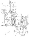
- the drive unit 41 includes a drive mechanism 43 that drives the winding drum 63 as shown in FIG.
- the drive mechanism 43 includes a motor 45 as a drive source, an ECU (electronic control unit) 47 for electronically controlling the motor 45, a reduction gear mechanism 49 for reducing the rotational output from the motor 45, and transmission and disconnection of the drive force.
- a clutch mechanism 51 is provided.
- the motor 45 is a reversible motor that can rotate in either the forward or reverse direction. The rotational output from the motor 45 is transmitted to the power shaft 53 via the reduction gear mechanism 49 and the clutch mechanism 51.
- a serration 53 a is formed on the outer peripheral surface of the power shaft 53.
- a seal member such as an O-ring is provided between the power shaft 53 and the main body of the drive unit 41, and moisture enters the drive unit 41 through the power shaft 53. Is preventing.
- the drive unit 41 also has a connection hole 55 through which the bolt 73 of the drum unit 61 passes when connected to the drum unit 61.
- the drum unit 61 includes a guide member G and a take-up drum 63.
- the guide member G is a member for guiding the intermediate portion of the cable 31 from the side of the center guide rail 11 fixed to the vehicle body to the take-up drum 63.
- an intermediate pulley 65 is used.
- the winding drum 63 is formed in a cylindrical shape, and an engagement groove 67 (see FIG. 6) is formed on the cylindrical outer peripheral surface.
- the engagement groove 67 is a groove for sequentially engaging the cable 31, and the cable 31 is wound around the winding drum 63 along the engagement groove 67.
- a recess 69 see FIG.
- the power shaft 53 in which the serration 53a is formed and the recess 69 in which the serration 69a is formed correspond to the power transmission mechanism in the present invention.
- the drive mechanism 43 rotationally drives the take-up drum 63 via the power shaft 53.
- the winding drum 63 rotates and winds up the cable 31, the slide door 2 can be driven to reciprocate according to the rotation direction.
- the slide door 2 when the slide door 2 is closed (the state shown in FIG. 2A), when the motor 45 is driven to rotate forward to rotate the winding drum 63 in one direction, the cable 31 is wound around the winding drum 63. The cable 31 is taken out from the winding drum 63. Since the end portion of the cable 31 is locked at a predetermined position on the side of the vehicle body (in this case, behind the vehicle 1 and to the right in FIG. 2A), the slide door 2 to which the drum unit 61 is fixed is It moves to the rear of the vehicle 1 along the guide rails 11, 12, and 13 via the guide roller unit 21 that slides on the guide rails 11, 12, and 13. As a result, the slide door 2 is opened. On the other hand, when the slide door 2 is opened (the state shown in FIG.
- the slide door 2 to which the drum unit 61 is fixed is It moves to the front of the vehicle 1 along the guide rails 11, 12, 13 via the guide roller unit 21 that slides on the guide rails 11, 12, 13. As a result, the slide door 2 is closed.
- the drum unit 61 includes a base plate 71 and a cover case 77 fixed to the base plate 71, and the take-up drum 63 and the intermediate pulley 65 serving as the guide member G are respectively rotatable on the base plate 71. It is fixed.
- Bolt portions 73 are formed on the base plate 71.
- the bolt part 73 is formed at a position corresponding to the connection hole 55 of the drive unit 41, and the drive unit 41 and the drum unit 61 are connected and fixed by being tightened with a nut after passing through the connection hole 55. That is, the bolt part 73 and the nut corresponding to this correspond to the connecting means in the present invention.
- three bolt portions 73 are provided at positions that divide the circumference of the rotation center axis of the winding drum 63 into three equal parts, and when the drive mechanism 43 is driven by supporting at three points.
- the drive unit 41 and the drum unit 61 can be securely fixed.
- the base plate 71 is further formed with a fixing hole 75 in the vicinity of a portion where the intermediate pulley 65 is pivotally supported. Through this fixing hole 75, the inner panel 5 and the entire drum unit 61 are securely fixed with screws or the like.
- the base plate 71 is preferably formed of a material having high rigidity.
- the base plate 71 is a metal plate.
- the metal base plate 71 to which the winding drum 63 and the intermediate pulley 65 are fixed is disposed to face the inner panel 5 (see FIG. 2).
- the metal base plate 71 has rigidity sufficient to withstand the tension acting between the winding drum 63 and the intermediate pulley 65 when the driving mechanism 43 is driven, but is integrated with the inner panel 5.
- the rigidity is further reinforced by being sandwiched and fixed between the drive unit 41 and the drum unit 61.
- the base plate 71 may be warped or in some cases a drum unit. It is possible to prevent the 61 itself from being damaged.
- the vehicle door opening / closing device 6 further includes a pulley mechanism 81 provided adjacent to the drum unit 61.
- the pulley mechanism 81 has a pair of guide pulleys 82 rotatably supported in a pulley case 83, and the pulley case 83 is fixed to the base bracket 22 (see FIG. 5) of the guide roller unit 21.
- the cable 31 guided to the pulley mechanism 81 via the intermediate pulley 65 of the drum unit 61 is crossed so as to be guided on both sides of the guide pulley 82 in the pulley case 83, and then the figure 8 is drawn.
- the pulley mechanism 81 functions as a tension mechanism for applying an appropriate tension to the cable 31 when the vehicle door opening / closing device 6 is driven.
- FIG. 6 is an explanatory diagram for explaining the arrangement relationship between the drum unit 61 and the pulley mechanism 81.
- the plane P1 perpendicular to the rotation center axis of the winding drum 63 and the plane P2 perpendicular to the rotation center axis of the guide pulley 82 in the pulley case 83 are twisted by exactly 90 degrees. It has become.
- the direction extending from the pulley mechanism 81 and the direction converging to the winding drum 63 are matched. Therefore, for the other cable 31b, the direction extending from the take-up drum 63 and the direction converging to the pulley mechanism 81 are greatly twisted. Therefore, the intermediate pulley 65 in the present embodiment is provided on the base plate 71 of the drum unit 61 so as to be twisted by about 45 degrees with each of the rotation center axis of the winding drum 63 and the rotation center axis of the guide pulley 82. Thereby, the cable 31 can change the direction smoothly in the site
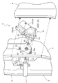
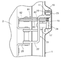
- the drive unit 41 and the drum unit 61 are provided inside the slide door 2 of the vehicle 1 as shown in FIG.
- the slide door 2 of the vehicle 1 is formed by an outer door O formed by an outer panel 3 and an inner panel 5 formed by press parts, and an inner panel 5 and an interior material 4 provided on the inner side of the vehicle. And an inner door I.
- the drive unit 41 and the drum unit 61 are disposed separately on both sides of the inner panel 5 constituting the slide door 2.
- the drum unit 61 is disposed on the inner panel 5 between the outer panel 3 and the inner panel 5 constituting the slide door 2 of the vehicle 1 (outer door O), and the drive unit 41 is connected to the vehicle 1. It is arranged between the interior material 4 constituting the slide door 2 and the inner panel 5 (inner door I), and is connected and fixed to the drum unit 61 via the inner panel 5.
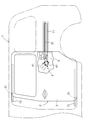
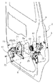
- FIG. 4 is an explanatory diagram for explaining an assembly procedure to the vehicle 1.
- This figure shows the inner panel 5 as seen from the inside of the inner door I.
- An opening is provided in the inner panel 5 at a position corresponding to the bolt part 73 of the drum unit 61.
- the bolt part 73 of the drum unit 61 is passed through the opening, and a nut (not shown)
- the drum unit 61 is attached to the inner panel 5 inside the outer door O by temporarily fixing with a clip or the like. If the drum unit 61 is attached to the inner panel 5 from the inside of the outer door O in this way, the cable 31 can be disposed on the center guide rail 11 without penetrating the inner panel 5, which facilitates the disposition work.
- the serration 53a formed on the power shaft 53 of the drive unit 41 and the serration 69a formed on the recess 69 of the winding drum 63 of the drum unit 61 are engaged with each other. Then, a nut or clip (not shown) that temporarily fixed the drum unit 61 is removed, and the bolt portion 73 protruding from the opening of the inner panel 5 is passed through the connecting hole 55 of the drive unit 41 and fixed with the nut. The drum unit 61, the inner panel 5, and the drive unit 41 are fastened together.
- the drive unit 41 and the drum unit 61 are separately disposed on both sides of the inner panel 5 constituting the slide door 2, and the drive unit 41 is connected to the drive unit 41 by the bolt portion 73 and the corresponding nut.
- the drum unit 61 is connected with the inner panel 5 interposed therebetween.
- serrations 53a and 69a are formed in the power shaft 53 that outputs the rotational driving force of the drive unit 41 and the recess 69 provided in the central portion of the winding drum 63, respectively, so that they engage with each other.
- the power transmission mechanism that transmits the rotational driving force of the drive unit 41 to the take-up drum 63 can be freely engaged, so that the drum unit 61 and the drive unit 41 can be separate units. . Therefore, it is possible to assemble them sequentially for each unit as described above, and to reduce the burden on the operator when assembling the vehicle door opening and closing device 6 to the vehicle 1 by dispersing the holding weight. be able to.
- the inner panel 5 is formed with a through hole 5a penetrating on one surface side and the other surface side.
- a base plate 71 can be fitted into the through hole 5a.
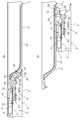
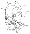
- the drum unit 61 is disposed on one surface side of the base plate 71 and the drive unit 41 is disposed on the other surface side, and is disposed in the through hole 5a (FIGS. 7 and 8).
- the base plate 71 that is a member of the inner panel 5 is formed with a flange 71a that faces and joins the inner panel 5 and a recess 71b that accommodates, for example, the drive unit 41 therein.
- the drum unit 61 is attached to the opposite side across the recess 71b.
- the base plate 71 is connected and fixed to the inner panel 5 by a bolt portion 73 which is a connecting means and a nut corresponding thereto.
- the drive unit 41 and the drum unit 61 are previously formed and the unit connected and fixed to the base plate 71 is formed, and the drive unit is easily assembled by assembling the unit to the inner panel 5 so as to close the through hole 5a. 41 and the drum unit 61 can be attached to the inner panel 5.
- the base plate 71 and the inner panel 5 are integrated with the flange 71a and the inner panel 5 being overlapped, the rigidity of the inner panel 5 is increased. Therefore, for example, even when a large tension is applied to the cable 31 between the winding drum 63 and the guide member G when the winding drum 63 is driven to rotate to wind the cable 31, the base plate 71 is warped or the drum unit 61 itself Can be prevented from being damaged.
- the mounting surface of the drive unit 41 and the drum unit 61 with respect to the base plate 71 may be configured to be flush with the surface of the inner panel 5 in a sectional view.
- the surface on which the drive unit 41 and the drum unit 61 are attached can be made different from the surface based on the surface of the inner panel 5 depending on the depth of the recess 71 b formed in the base plate 71.
- the same drive unit 41 and drum unit 61 are attached to different vehicle types, only the shape of the base plate 71 needs to be changed.
- the drive unit 41 and the drum unit 61 can be shared between different vehicle types to reduce costs, for example, a window attached to the inside of the slide door 2 Interference with members such as can be prevented.
- the drum unit 61 is disposed in the space between the outer panel 3 and the inner panel 5 and the drive unit 41 is disposed in the space between the interior material 4 and the inner panel 5 as in the above-described embodiment. Be placed. Further, the drum unit 61 is provided with a guide member G for changing the direction of the cable 31 extending from the winding drum 63, and the winding drum 63 and the guide member G are fixed to the base plate 71 (FIG. 8). .
- the guide member G is preferably provided in the vicinity of the take-up drum 63 so that the attachment position can be appropriately set with respect to the base plate 71 (FIGS. 9 and 10).
- the intermediate pulley 65 is connected in advance to an attachment member having a long hole so that the intermediate pulley 65 is in an optimal position. Secure to.
- the degree of freedom of cable arrangement increases, for example, the pitch between the paths of the cable 31 can be arbitrarily set.
- the sliding surface 65a with the pin 66 which is a support member for rotatably mounting the intermediate pulley 65 to the base plate 71 is curved along the axial direction of the pin 66 (R shape). ) (FIGS. 11 and 12).
- the pin 66 is pivotally supported at its upper and lower ends by a cover case 77 and a base plate 71, respectively.
- the sliding surface 65a has an R shape, so that the posture of the intermediate pulley 65 can be correctly maintained.
- the intermediate pulley 65 is provided in the vicinity of the winding drum 63, the cable 31 can be reduced in the wiring space.
- the intermediate pulley 65 is used as the guide member G for guiding the cable 31 from the side of the center guide rail 11 fixed to the vehicle 1 to the winding drum 63 .
- a guide shoe (guide groove) 68 for guiding the direction change while sliding the cable 31 may be used.
- the guide shoe may be provided in the drum unit 61 (FIG. 8).
- the cable 31 is formed of a single wire, and both ends of the cable 31 are locked to predetermined portions of the vehicle body side portion near the front end and the rear end of the center guide rail 11 in the front-rear direction of the vehicle 1.
- the example to do was demonstrated.
- the cable 31 may be connected in a ring shape and locked to the vehicle 1 at any one or more locations.
- the cable 31 is composed of two wires, one end of which is the winding drum 63 and the other end of the center guide rail 11 in the front-rear direction of the vehicle 1 in the front-rear direction of the vehicle 1 or the vehicle body side. You may latch to the predetermined site
- the present invention can be suitably used for a vehicle door opening / closing device that opens and closes a door provided on a side of the vehicle.
Landscapes
- Power-Operated Mechanisms For Wings (AREA)
- Closing And Opening Devices For Wings, And Checks For Wings (AREA)
Abstract
Description
また、ドラムユニットと駆動ユニットとが別ユニットであるので、これらを各ユニットごとに順次組み付けることが可能となり、保持重量を分散させることで、車両への組み付け時の作業者の負担を軽減することができる。
したがって、車両への組み付け時の作業者の負担を軽減するとともに、低コストで確実に駆動機構を防水環境に置くことのできる車両用ドア開閉装置を提供することができる。
また、当該ドラムユニットにおいて、巻取ドラム及び案内部材がインナーパネルに対向配置されるベースプレートに固定してあり、当該ベースプレートとインナーパネルとを挟持するように駆動ユニットとドラムユニットとが連結されるので、ベースプレートとインナーパネルとが一体となってそれぞれ剛性を補強し合う。よって、巻取ドラムが回転駆動してケーブルを巻き取る時に巻取ドラムと案内部材との間のケーブルに大きな張力が作用したとしても、ベースプレートが反り返ったり、場合によってはドラムユニット自体が破損したりするのを防止することができる。
また、当該ベースプレートを挟持するように駆動ユニットとドラムユニットとが連結されるので、ベースプレートとインナーパネルとが一体となってそれぞれ剛性を補強し合うように構成できる。
図1は、本発明に係る車両用ドア開閉装置6を備えた車両1の側面図である。この車両1には車両用ドア開閉装置6が備えられ、スライドドア2の開閉動作を自動で行うことができる。
上述した実施形態では、インナーパネル5を挟持しつつ駆動ユニット41とドラムユニット61とを連結手段によって連結する場合について説明したが、以下のように構成してもよい。
即ち、インナーパネル5に、一方の面側および他方の面側に貫通する貫通孔5aを形成する。この貫通孔5aにはベースプレート71を嵌め込むことができる。このベースプレート71の一方の面側にドラムユニット61を配置すると共に他方の面側に駆動ユニット41を配置し、貫通孔5aに配設する(図7,8)。
インナーパネル5の一部材となるベースプレート71は、インナーパネル5と対面して接合する鍔部71aと、例えば駆動ユニット41をその内部に収容する凹部71bを形成してある。ドラムユニット61は凹部71bを隔てた反対側に取り付ける。ベースプレート71は連結手段であるボルト部73及びこれに対応するナットによりインナーパネル5に連結固定される。
さらに、ドラムユニット61には、巻取ドラム63から延出したケーブル31の方向を変更する案内部材Gを備えており、巻取ドラム63及び案内部材Gがベースプレート71に固定してある(図8)。
上述した実施形態において、案内部材Gは、巻取ドラム63の近傍に設け、ベースプレート71に対して取り付け位置を適宜設定できるように構成するとよい(図9,10)。
例えば、案内部材G(中間プーリー65)をベースプレート71に組み付けるとき、予め、長孔を設けた取付部材に中間プーリー65を連結しておき、この取付部材を中間プーリー65が最適な位置となるように固定する。このように案内部材Gを構成することで、ケーブル31の経路間ピッチが任意に設定できるなど、ケーブル配設の自由度が高まる。
これにより、例えばピン66が傾いて取り付けられた場合であっても、摺動面65aがR形状となっているため、中間プーリー65の姿勢を正しく維持することができる。
(1)上記の実施形態においては、動力伝達機構として、セレーション53aが形成された動力軸53及びセレーション69aが形成された凹部69を採用した例について説明した。しかし、互いに係合することにより、駆動ユニット41の回転駆動力を巻取ドラム63に伝達するとともに、巻取ドラム63と駆動ユニット41とを係脱自在なものとすることができれば、これ以外の機構を採用することもできる。例えば、動力軸53及び凹部69にそれぞれスプラインを形成したもの等であっても良い。
(3)上記の実施形態においては、ボルト部73が巻取ドラム63の回転中心軸の周囲を三等分する位置に三個設けられ、三点で支持する例について説明した。しかし、ボルト部73の個数については三個に限られず、四点以上で支持しても良い。また、駆動機構43が駆動した際に駆動ユニット41とドラムユニット61とが確実に固定されるのであれば、ボルト部73の個数を二個のみとし、二点で支持するようにしてあっても良い。
Claims (10)
- 車両ドアを構成するインナーパネルの一方の面側に配置され、車両と当該車両のドアとに亘って配設されたケーブルを巻き取り可能な巻取ドラムを備えたドラムユニットと、
前記インナーパネルの他方の面側に配置され、前記巻取ドラムを駆動する駆動ユニットと、
前記駆動ユニットの回転駆動力を前記巻取ドラムに伝達するとともに、前記巻取ドラムと前記駆動ユニットとを係脱自在なものとする動力伝達機構と、
前記インナーパネルを挟持しつつ前記駆動ユニットと前記ドラムユニットとを連結する連結手段と、を備えた車両用ドア開閉装置。 - 前記ドラムユニットは、前記車両ドアを構成するアウターパネルと前記インナーパネルとの間に配置され、前記駆動ユニットは、前記車両ドアを構成する内装材と前記インナーパネルとの間に配置される請求項1に記載の車両用ドア開閉装置。
- 前記ドラムユニットは、前記巻取ドラムから延出した前記ケーブルの方向を変更する案内部材を備えており、前記巻取ドラム及び前記案内部材が、前記インナーパネルに対向配置されるベースプレートに固定してある請求項1又は2に記載の車両用ドア開閉装置。
- 前記インナーパネルは、前記一方の面側および前記他方の面側に貫通する貫通孔を有し、
前記一方の面側にドラムユニットを配置すると共に前記他方の面側に前記駆動ユニットを配置するベースプレートを、前記貫通孔に配設した請求項1に記載の車両用ドア開閉装置。 - 前記ドラムユニットは、前記車両ドアを構成するアウターパネルと前記インナーパネルとの間に配置され、前記駆動ユニットは、前記車両ドアを構成する内装材と前記インナーパネルとの間に配置される請求項4に記載の車両用ドア開閉装置。
- 前記ドラムユニットは、前記巻取ドラムから延出した前記ケーブルの方向を変更する案内部材を備えており、前記巻取ドラム及び前記案内部材が前記ベースプレートに固定してある請求項4又は5に記載の車両用ドア開閉装置。
- 前記案内部材は、前記ベースプレートに対して取付位置変更可能に構成してある請求項3又は6に記載の車両用ドア開閉装置。
- 前記案内部材は、前記ベースプレートに配設されたプーリーである請求項3、6又は7に記載の車両用ドア開閉装置。
- 前記案内部材は、前記ドラムユニットに備えた案内溝である請求項3又は6に記載の車両用ドア開閉装置。
- 前記プーリーは、前記プーリーを前記ベースプレートに回転自在に支持する支持部材に対する摺接面を備え、当該摺接面は、前記支持部材の軸芯方向に沿って湾曲した形状を呈する請求項8に記載の車両用ドア開閉装置。
Priority Applications (4)
| Application Number | Priority Date | Filing Date | Title |
|---|---|---|---|
| JP2010500738A JP5488926B2 (ja) | 2008-02-28 | 2009-02-26 | 車両用ドア開閉装置 |
| EP09714313.5A EP2246210B1 (en) | 2008-02-28 | 2009-02-26 | Vehicle door opening/closing device |
| CN2009801004172A CN101932464B (zh) | 2008-02-28 | 2009-02-26 | 车辆用门开闭装置 |
| US12/679,261 US8336259B2 (en) | 2008-02-28 | 2009-02-26 | Vehicle door opening/closing apparatus |
Applications Claiming Priority (2)
| Application Number | Priority Date | Filing Date | Title |
|---|---|---|---|
| JP2008048547 | 2008-02-28 | ||
| JP2008-048547 | 2008-02-28 |
Publications (1)
| Publication Number | Publication Date |
|---|---|
| WO2009107722A1 true WO2009107722A1 (ja) | 2009-09-03 |
Family
ID=41016109
Family Applications (1)
| Application Number | Title | Priority Date | Filing Date |
|---|---|---|---|
| PCT/JP2009/053562 Ceased WO2009107722A1 (ja) | 2008-02-28 | 2009-02-26 | 車両用ドア開閉装置 |
Country Status (5)
| Country | Link |
|---|---|
| US (1) | US8336259B2 (ja) |
| EP (1) | EP2246210B1 (ja) |
| JP (1) | JP5488926B2 (ja) |
| CN (1) | CN101932464B (ja) |
| WO (1) | WO2009107722A1 (ja) |
Cited By (5)
| Publication number | Priority date | Publication date | Assignee | Title |
|---|---|---|---|---|
| JP2010185270A (ja) * | 2009-01-16 | 2010-08-26 | Aisin Seiki Co Ltd | 車両用ドア開閉装置 |
| JP2011074651A (ja) * | 2009-09-30 | 2011-04-14 | Aisin Seiki Co Ltd | 車両用ドア開閉装置 |
| US8800205B2 (en) | 2009-01-16 | 2014-08-12 | Aisin Seiki Kabushiki Kaisha | Door opening-and-closing apparatus for vehicle |
| WO2015098897A1 (ja) * | 2013-12-25 | 2015-07-02 | アイシン精機 株式会社 | 開閉体の開閉装置 |
| JP2016107759A (ja) * | 2014-12-04 | 2016-06-20 | アイシン精機株式会社 | スライドドアモジュール |
Families Citing this family (13)
| Publication number | Priority date | Publication date | Assignee | Title |
|---|---|---|---|---|
| US7856759B2 (en) * | 2008-12-18 | 2010-12-28 | Ford Global Technologies, Llc | Dual action power drive unit for a vehicle door |
| CN102278032B (zh) * | 2011-07-08 | 2014-04-23 | 宁波市胜源技术转移有限公司 | 一种用于车门滑道的传动系统 |
| JP5817575B2 (ja) * | 2012-02-08 | 2015-11-18 | トヨタ自動車株式会社 | 車両のスライドドア構造 |
| KR20150074806A (ko) * | 2013-12-24 | 2015-07-02 | 기아자동차주식회사 | 차량용 슬라이딩 도어 |
| US9476245B2 (en) | 2014-08-29 | 2016-10-25 | Strattec Power Access Llc | Door cable pulley system |
| KR101637289B1 (ko) * | 2014-11-06 | 2016-07-07 | 현대자동차 주식회사 | 차량용 슬라이딩 도어장치 |
| US10443288B2 (en) | 2015-02-04 | 2019-10-15 | Mitsuba Corporation | Roller unit and vehicular opening-closing body driving device |
| US10633908B1 (en) | 2017-08-21 | 2020-04-28 | Zoox, Inc. | Vehicle door actuator assembly |
| US10895097B2 (en) * | 2018-09-17 | 2021-01-19 | Hi-Lex Controls, Inc. | Drive unit assembly for a window regulator |
| US11002060B2 (en) | 2018-09-17 | 2021-05-11 | Hi-Lex Controls, Inc. | Drive unit assembly for a window regulator |
| CN109084070B (zh) * | 2018-11-01 | 2023-10-27 | 山东龙腾电力科技有限公司 | 一种防爆型通风柜风阀传动机构 |
| JP6854310B2 (ja) * | 2019-03-11 | 2021-04-07 | 三井金属アクト株式会社 | 車両スライド扉の動力スライド装置 |
| KR102854813B1 (ko) * | 2020-05-13 | 2025-09-04 | 현대자동차주식회사 | 슬라이딩도어용 가이드기구 |
Citations (5)
| Publication number | Priority date | Publication date | Assignee | Title |
|---|---|---|---|---|
| JPH06511450A (ja) * | 1992-08-04 | 1994-12-22 | メカプラスト・エス・アー・エム | 複数の機能を統合した車両ドア・プラテン及びその組立て方法 |
| JP2001513726A (ja) * | 1997-02-27 | 2001-09-04 | ブローゼ・ファールツォイグタイレ・ゲーエムベーハー・ウント・コ・カーゲー・コブルグ | 自動車の調節装置用のモーターギアユニット |
| JP2001336352A (ja) * | 2000-05-29 | 2001-12-07 | Aisin Seiki Co Ltd | 車両用スライドドア装置 |
| JP2003074253A (ja) * | 2001-09-07 | 2003-03-12 | Aisin Seiki Co Ltd | 車両用スライドドア装置 |
| JP2005273162A (ja) * | 2004-03-23 | 2005-10-06 | Mitsui Mining & Smelting Co Ltd | 車両スライド扉の動力スライド装置 |
Family Cites Families (21)
| Publication number | Priority date | Publication date | Assignee | Title |
|---|---|---|---|---|
| US3530619A (en) | 1967-09-18 | 1970-09-29 | Farrel Corp | Grinding machine |
| JPS5235018U (ja) * | 1975-09-04 | 1977-03-12 | ||
| JPS5235018A (en) | 1975-09-12 | 1977-03-17 | Hitachi Ltd | Carriage construction of a vehicle |
| US5890321A (en) * | 1996-08-05 | 1999-04-06 | General Motors Corporation | Window regulator mounting panel |
| FR2799493B1 (fr) * | 1999-10-07 | 2001-11-23 | Sai Automotive Sal Gmbh | Ensemble comprenant une doublure interieure de portiere de vehicule et un mecanisme leve-vitre fixe a cette doublure |
| JP2001199236A (ja) | 2000-01-20 | 2001-07-24 | Yazaki Corp | 自動車ドアの補機組付構造及び補機組付方法 |
| DE60110663T2 (de) * | 2000-03-10 | 2006-02-02 | Arvinmeritor Light Vehicle Systems-France | Verfahren und Gerät zum Montieren eines Antriebsmechanismus in einem Türmodul |
| US6574922B2 (en) * | 2000-10-06 | 2003-06-10 | Meritor Light Vehicle Systems | Door trimming panel having a window-lift mechanism |
| JP4602614B2 (ja) * | 2001-09-26 | 2010-12-22 | アイシン精機株式会社 | 自動車用ドア |
| AU2003258410A1 (en) * | 2002-08-20 | 2004-03-11 | Intier Automotive Closures Inc. | Window regulator assembly |
| JP4214242B2 (ja) | 2002-10-25 | 2009-01-28 | 関東自動車工業株式会社 | 小型自動車のパワースライドドア装置 |
| US7591104B2 (en) * | 2003-07-23 | 2009-09-22 | Ohi Seisakusho Co., Ltd. | Mounting structure of a power window apparatus |
| DE20313273U1 (de) * | 2003-08-21 | 2004-09-30 | Brose Fahrzeugteile Gmbh & Co. Kg, Coburg | Antriebssystem für Verstelleinrichtungen in Kraftfahrzeugen |
| JP4479272B2 (ja) * | 2004-02-23 | 2010-06-09 | アイシン精機株式会社 | 開閉体の駆動装置 |
| US7530199B2 (en) | 2004-03-22 | 2009-05-12 | Mitsui Mining And Smelting Co., Ltd. | Method for controlling sliding speed of vehicle slide door |
| DE502006006190D1 (de) | 2005-08-11 | 2010-04-01 | Brose Schliesssysteme Gmbh | Schiebetür |
| US8011136B2 (en) * | 2006-01-19 | 2011-09-06 | Hi-Lex Corporation | Power closure actuator |
| JP2007217865A (ja) | 2006-02-14 | 2007-08-30 | Mitsuba Corp | 車両用自動開閉装置 |
| US7823330B2 (en) * | 2006-03-09 | 2010-11-02 | Strattec Power Access Llc | Apparatus and method for drums in a sliding door mechanism |
| US8096606B2 (en) * | 2008-10-20 | 2012-01-17 | Mitsui Kinzoku Act Corporation | Door-opening device in a vehicle sliding door |
| US7856759B2 (en) * | 2008-12-18 | 2010-12-28 | Ford Global Technologies, Llc | Dual action power drive unit for a vehicle door |
-
2009
- 2009-02-26 CN CN2009801004172A patent/CN101932464B/zh not_active Expired - Fee Related
- 2009-02-26 US US12/679,261 patent/US8336259B2/en not_active Expired - Fee Related
- 2009-02-26 JP JP2010500738A patent/JP5488926B2/ja not_active Expired - Fee Related
- 2009-02-26 WO PCT/JP2009/053562 patent/WO2009107722A1/ja not_active Ceased
- 2009-02-26 EP EP09714313.5A patent/EP2246210B1/en not_active Not-in-force
Patent Citations (5)
| Publication number | Priority date | Publication date | Assignee | Title |
|---|---|---|---|---|
| JPH06511450A (ja) * | 1992-08-04 | 1994-12-22 | メカプラスト・エス・アー・エム | 複数の機能を統合した車両ドア・プラテン及びその組立て方法 |
| JP2001513726A (ja) * | 1997-02-27 | 2001-09-04 | ブローゼ・ファールツォイグタイレ・ゲーエムベーハー・ウント・コ・カーゲー・コブルグ | 自動車の調節装置用のモーターギアユニット |
| JP2001336352A (ja) * | 2000-05-29 | 2001-12-07 | Aisin Seiki Co Ltd | 車両用スライドドア装置 |
| JP2003074253A (ja) * | 2001-09-07 | 2003-03-12 | Aisin Seiki Co Ltd | 車両用スライドドア装置 |
| JP2005273162A (ja) * | 2004-03-23 | 2005-10-06 | Mitsui Mining & Smelting Co Ltd | 車両スライド扉の動力スライド装置 |
Cited By (6)
| Publication number | Priority date | Publication date | Assignee | Title |
|---|---|---|---|---|
| JP2010185270A (ja) * | 2009-01-16 | 2010-08-26 | Aisin Seiki Co Ltd | 車両用ドア開閉装置 |
| US8800205B2 (en) | 2009-01-16 | 2014-08-12 | Aisin Seiki Kabushiki Kaisha | Door opening-and-closing apparatus for vehicle |
| JP2011074651A (ja) * | 2009-09-30 | 2011-04-14 | Aisin Seiki Co Ltd | 車両用ドア開閉装置 |
| WO2015098897A1 (ja) * | 2013-12-25 | 2015-07-02 | アイシン精機 株式会社 | 開閉体の開閉装置 |
| JP2015124490A (ja) * | 2013-12-25 | 2015-07-06 | アイシン精機株式会社 | 開閉体開閉装置 |
| JP2016107759A (ja) * | 2014-12-04 | 2016-06-20 | アイシン精機株式会社 | スライドドアモジュール |
Also Published As
| Publication number | Publication date |
|---|---|
| JP5488926B2 (ja) | 2014-05-14 |
| JPWO2009107722A1 (ja) | 2011-07-07 |
| US20100251619A1 (en) | 2010-10-07 |
| EP2246210A4 (en) | 2014-03-05 |
| CN101932464A (zh) | 2010-12-29 |
| US8336259B2 (en) | 2012-12-25 |
| EP2246210A1 (en) | 2010-11-03 |
| CN101932464B (zh) | 2013-08-07 |
| EP2246210B1 (en) | 2017-07-05 |
Similar Documents
| Publication | Publication Date | Title |
|---|---|---|
| JP5488926B2 (ja) | 車両用ドア開閉装置 | |
| JP4508228B2 (ja) | スイングスライドドアの開閉装置 | |
| US6257303B1 (en) | Rack and pinion door drive system | |
| US7866732B2 (en) | Compact cable drive power sliding door mechanism | |
| US7770961B2 (en) | Compact cable drive power sliding door mechanism | |
| EP2210752A1 (en) | Device for opening and closing vehicle door | |
| WO2016021080A1 (ja) | ドア開閉装置 | |
| US20080190028A1 (en) | Compact Cable Drive Power Sliding Door Mechanism | |
| JP6843231B2 (ja) | ウィンドウレギュレータ用の駆動装置 | |
| JP5578067B2 (ja) | スライドドア開閉装置及びその組付け方法 | |
| KR102244852B1 (ko) | 케이블 드럼을 위한 정지 링을 갖는 윈도우 리프터를 위한 구동 조립체 | |
| JP2017137014A (ja) | 可動ホーム柵 | |
| JP2007113205A (ja) | ワイヤ巻回装置 | |
| FR2743532A1 (fr) | Structure d'installation et procede d'assemblage d'elements de porte de vehicule | |
| JP2011094426A (ja) | 車両のスライドドアの開閉駆動装置 | |
| JP7723241B2 (ja) | 車両用スライド窓パネル開閉装置 | |
| JP7723240B2 (ja) | 車両用スライド窓パネル開閉装置 | |
| KR101134372B1 (ko) | 케이블 타입의 파워트렁크 | |
| CN217233204U (zh) | 车辆用滑动门开闭装置 | |
| KR20240055513A (ko) | 전자식 주차 브레이크 기어시스템 조립구조 | |
| JP2009046920A (ja) | 車両用自動開閉装置 | |
| JP2019090257A (ja) | ドアラッチ装置 | |
| JP6019495B2 (ja) | 車両用ドアの開閉駆動装置 | |
| CN116065915A (zh) | 机动车辆滑动闭合面板线缆操作式驱动系统的致动器组件 | |
| CN114635618A (zh) | 具有带快速连接式联接装置的线缆系统的动力滑动门组件 |
Legal Events
| Date | Code | Title | Description |
|---|---|---|---|
| WWE | Wipo information: entry into national phase |
Ref document number: 200980100417.2 Country of ref document: CN |
|
| 121 | Ep: the epo has been informed by wipo that ep was designated in this application |
Ref document number: 09714313 Country of ref document: EP Kind code of ref document: A1 |
|
| WWE | Wipo information: entry into national phase |
Ref document number: 2010500738 Country of ref document: JP |
|
| REEP | Request for entry into the european phase |
Ref document number: 2009714313 Country of ref document: EP |
|
| WWE | Wipo information: entry into national phase |
Ref document number: 2009714313 Country of ref document: EP |
|
| WWE | Wipo information: entry into national phase |
Ref document number: 12679261 Country of ref document: US |
|
| NENP | Non-entry into the national phase |
Ref country code: DE |
|
| WWE | Wipo information: entry into national phase |
Ref document number: 2010144537 Country of ref document: RU |