WO2009110097A1 - Articulation du genou comprenant un mécanisme de verrou manuel et cuisse artificielle - Google Patents
Articulation du genou comprenant un mécanisme de verrou manuel et cuisse artificielle Download PDFInfo
- Publication number
- WO2009110097A1 WO2009110097A1 PCT/JP2008/054178 JP2008054178W WO2009110097A1 WO 2009110097 A1 WO2009110097 A1 WO 2009110097A1 JP 2008054178 W JP2008054178 W JP 2008054178W WO 2009110097 A1 WO2009110097 A1 WO 2009110097A1
- Authority
- WO
- WIPO (PCT)
- Prior art keywords
- knee joint
- lock
- knee
- upper member
- manual
- Prior art date
- Legal status (The legal status is an assumption and is not a legal conclusion. Google has not performed a legal analysis and makes no representation as to the accuracy of the status listed.)
- Ceased
Links
Images


Classifications
-
- A—HUMAN NECESSITIES
- A61—MEDICAL OR VETERINARY SCIENCE; HYGIENE
- A61F—FILTERS IMPLANTABLE INTO BLOOD VESSELS; PROSTHESES; DEVICES PROVIDING PATENCY TO, OR PREVENTING COLLAPSING OF, TUBULAR STRUCTURES OF THE BODY, e.g. STENTS; ORTHOPAEDIC, NURSING OR CONTRACEPTIVE DEVICES; FOMENTATION; TREATMENT OR PROTECTION OF EYES OR EARS; BANDAGES, DRESSINGS OR ABSORBENT PADS; FIRST-AID KITS
- A61F2/00—Filters implantable into blood vessels; Prostheses, i.e. artificial substitutes or replacements for parts of the body; Appliances for connecting them with the body; Devices providing patency to, or preventing collapsing of, tubular structures of the body, e.g. stents
- A61F2/50—Prostheses not implantable in the body
- A61F2/60—Artificial legs or feet or parts thereof
- A61F2/64—Knee joints
- A61F2/642—Polycentric joints, without longitudinal rotation
-
- A—HUMAN NECESSITIES
- A61—MEDICAL OR VETERINARY SCIENCE; HYGIENE
- A61F—FILTERS IMPLANTABLE INTO BLOOD VESSELS; PROSTHESES; DEVICES PROVIDING PATENCY TO, OR PREVENTING COLLAPSING OF, TUBULAR STRUCTURES OF THE BODY, e.g. STENTS; ORTHOPAEDIC, NURSING OR CONTRACEPTIVE DEVICES; FOMENTATION; TREATMENT OR PROTECTION OF EYES OR EARS; BANDAGES, DRESSINGS OR ABSORBENT PADS; FIRST-AID KITS
- A61F2/00—Filters implantable into blood vessels; Prostheses, i.e. artificial substitutes or replacements for parts of the body; Appliances for connecting them with the body; Devices providing patency to, or preventing collapsing of, tubular structures of the body, e.g. stents
- A61F2/50—Prostheses not implantable in the body
- A61F2/68—Operating or control means
- A61F2/74—Operating or control means fluid, i.e. hydraulic or pneumatic
- A61F2/748—Valve systems
-
- A—HUMAN NECESSITIES
- A61—MEDICAL OR VETERINARY SCIENCE; HYGIENE
- A61F—FILTERS IMPLANTABLE INTO BLOOD VESSELS; PROSTHESES; DEVICES PROVIDING PATENCY TO, OR PREVENTING COLLAPSING OF, TUBULAR STRUCTURES OF THE BODY, e.g. STENTS; ORTHOPAEDIC, NURSING OR CONTRACEPTIVE DEVICES; FOMENTATION; TREATMENT OR PROTECTION OF EYES OR EARS; BANDAGES, DRESSINGS OR ABSORBENT PADS; FIRST-AID KITS
- A61F2/00—Filters implantable into blood vessels; Prostheses, i.e. artificial substitutes or replacements for parts of the body; Appliances for connecting them with the body; Devices providing patency to, or preventing collapsing of, tubular structures of the body, e.g. stents
- A61F2/50—Prostheses not implantable in the body
- A61F2002/5072—Prostheses not implantable in the body having spring elements
-
- A—HUMAN NECESSITIES
- A61—MEDICAL OR VETERINARY SCIENCE; HYGIENE
- A61F—FILTERS IMPLANTABLE INTO BLOOD VESSELS; PROSTHESES; DEVICES PROVIDING PATENCY TO, OR PREVENTING COLLAPSING OF, TUBULAR STRUCTURES OF THE BODY, e.g. STENTS; ORTHOPAEDIC, NURSING OR CONTRACEPTIVE DEVICES; FOMENTATION; TREATMENT OR PROTECTION OF EYES OR EARS; BANDAGES, DRESSINGS OR ABSORBENT PADS; FIRST-AID KITS
- A61F2/00—Filters implantable into blood vessels; Prostheses, i.e. artificial substitutes or replacements for parts of the body; Appliances for connecting them with the body; Devices providing patency to, or preventing collapsing of, tubular structures of the body, e.g. stents
- A61F2/50—Prostheses not implantable in the body
- A61F2/68—Operating or control means
- A61F2002/6854—Operating or control means for locking or unlocking a joint
Definitions
- an upper member positioned on the upper side of the knee and a lower member positioned on the lower side of the knee are manually moved into a swingable unlocked state or a swingable locked state when the knee is extended.
- the present invention relates to a knee joint that can be switched, and a femoral prosthesis including the knee joint, and more particularly to a technique that is effective in reducing the size of a manual lock mechanism that switches between an unlocked state and a locked state.
- the knee joint serves as a knee joint that allows the upper member and the lower member to swing.
- a typical example of a prosthetic limb having such a knee joint is a thigh prosthesis.
- a prosthetic leg having a knee joint is usually provided with a drag generating means such as a pneumatic cylinder, a hydraulic cylinder, or a spring cylinder in order to effectively perform a swinging motion.
- a hydraulic cylinder or a spring cylinder is preferable to a pneumatic cylinder.
- the pneumatic cylinder since air is compressible, a repulsive force after the knee is bent to the maximum can be obtained.
- Patent Document 1 shows a prosthetic leg having a pneumatic cylinder
- Patent Document 2 shows a prosthetic leg having a hydraulic cylinder
- Patent Document 3 shows a prosthetic leg having a spring cylinder.
- Patent Document 4 shows a technique for preventing knee breakage that generates a braking action in response to a user's load and automatically locks / unlocks a swing motion during walking.
- An object of the present invention is to provide a technique capable of simplifying a manual lock mechanism capable of selectively switching between an unlocked state and a locked state during walking, and making a knee joint and a prosthetic leg including the manual lock mechanism compact. And, the present invention provides a technique that has a good appearance and can improve the switching operability of the manual lock mechanism. Other objects of the present invention will become clear from the following description.
- the connecting means for connecting the upper member and the lower member so as to be able to swing includes a swinging shaft, and it is considered to obtain a locked state by restricting the movement of the swinging shaft.
- the swing shaft is essential for knee joints and prosthetic legs, and aims to make the manual lock mechanism simple by using it as one component of the manual lock mechanism.
- the manual lock mechanism of the present invention has the following characteristics.
- the above-described swing shaft is one component of the manual lock mechanism, and includes an uneven portion that runs in the direction of its own axis.
- a lock member supported by a member that rotatably supports a swing shaft (that is, a swing shaft that is a target for restricting movement) of the upper member and the lower member is provided. It is possible to manually and selectively switch between a locked state in contact with the uneven portion of the dynamic shaft and an unlocked state away from the uneven portion.
- C When in the locked state, the lock member comes into contact with the first end portion in the longitudinal direction facing the concavo-convex portion, and suppresses movement of the upper member and the lower member to bend the knee.
- a single axis in which the swing center of the swing motion is constant, or the swing center of the swing motion changes with the swing There are multiple axes to do.
- the movement of a single single axis is restricted, and in the case of a multi-axis, the movement of one of a plurality of swing axes is restricted.
- the single single axis is located at the top of the knee joint, a person using a prosthetic leg including the knee joint has an outer second end opposite to the inner first end facing the single axis ( That is, the manual operation unit) can be operated by itself and can be easily switched to lock or unlock as required.
- the swing shaft located at the upper part of the knee joint should be restricted, and in this case, it is most preferable to support the lock member with respect to the socket mounting portion having sufficient mechanical strength.
- the form in which the movement of the rocking shaft is restricted and the rocking movement between the upper member and the lower member is locked is a form in which the upper member and the lower member extend the knee.
- the form is a form in which a wearer wearing a prosthetic leg can walk on a snowy road or rough terrain. Therefore, the form is a form from the knee angle of 0 ° where the upper member and the lower member extend straight to the knee angle of 20 ° which does not impede walking.
- the lock member In response to switching to the locked state or the unlocked state, the lock member changes between the locked state and the unlocked position. Therefore, it is preferable to provide a position restricting means for restricting the position so as to maintain the locked state or the unlocked state.
- a position restricting means for example, there are methods of dropping bolts or pins for position restriction so that they can be put in and out of shallow grooves, or utilizing catching of claws.
- the lock member can be switched between a locked state and an unlocked state by either a rotation operation or a slide operation.
- the movement associated with this switching is a movement in the horizontal plane of the lock member that is horizontally arranged for both the rotation operation and the slide operation. Therefore, only a small space is required for the locking member and its movement.
- This type of knee joint and a prosthesis including the knee joint are preferably provided with a drag generating means for generating a drag against knee flexion and extension by the knee joint in order to make the knee joint move effectively.
- a drag generating means any of a hydraulic cylinder, a spring cylinder, and a pneumatic cylinder can be used.
- the manual lock mechanism and the drag generating means are located inside the contour of the knee joint. Thereby, the thigh prosthesis is compact and looks good in appearance.
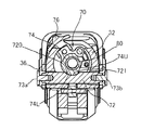
- FIG. 1 is a front view showing a first embodiment of a knee joint according to the present invention.
- FIG. 2 is a cross-sectional view taken along line 2-2 in FIG.
- FIG. 3 is a cross-sectional view taken along line 3-3 in FIG. It is a front view which shows another state of the knee joint of 1st Example.
- FIG. 5 is a cross-sectional view taken along line 5-5 in FIG.
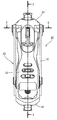
- FIG. 6 is a sectional view taken along line 6-6 in FIG. It is a front view which shows 2nd Example of the knee joint by this invention.
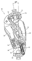
- FIG. 8 is a cross-sectional view taken along line 8-8 in FIG.
- FIG. 9 is a sectional view taken along line 9-9 in FIG.
- Knee joint (first embodiment) 32 Upper member 34 Lower member 36 Front side link 38 Rear side link 40 Connecting means 50 Extension assist mechanism 60 Hydraulic cylinder 70 Manual lock mechanism 72 Oscillating shaft 720 Uneven portion 721 First surface 722 Second surface 74 Lock member 76 Lever ( Manual operation part) 80 Nut member 230 Knee joint (second embodiment) 232 Upper member 234 Lower member 260 Pneumatic cylinder 272 Oscillating shaft 700 Manual lock mechanism (another example) 740 Lock member 742 Lock claw 760 Push button type manual operation portion 770 Stopper
- the knee joint 30 includes an upper member 32 positioned above the knee and a lower member 34 positioned below the knee and pivotably connected to the upper member 32 to allow the knee to bend.
- the upper member 32 integrally supports the alignment block 322 at the upper center portion.
- the alignment block 322 is a portion to which a socket (not shown) is attached, and supports the load of the prosthetic leg user through the thigh entering the socket.
- another alignment block 342 is provided at the lower central portion of the lower member 34.
- the alignment block 342 is a portion to which a leg member that supports the foot is attached. Therefore, the knee joint 30 constitutes a main part of the thigh prosthesis.
- the multi-axis connecting means 40 connects the upper member 32 and the lower member 34 so as to be swingable.
- the connecting means 40 is composed of a four-joint link mechanism.
- the four-node link mechanism is a limited chain in which four links are rotatably connected.
- the upper member 32 and the lower member 34 each function as one of the four links in the limited chain.
- the remaining two links are the front link 36 and the rear link 38.
- These links 36 and 38 have connecting portions 362 and 364; 382 and 384 with other links at upper and lower ends.
- both the front and rear links 36 and 38 have a symmetrical shape, and the upper and lower connecting portions are a pair of left and right.
- the front link 36 and the rear link 38 that are separated in the front-rear direction together surround the outer side of the knee joint 30 and define an inner space thereof.
- the knee joint 30 supports an extension assisting mechanism 50 between the lower member 34 and the rear link 38.
- the extension assisting mechanism 50 includes, in addition to the compression spring 52, two auxiliary links 54 and 56, and generates an extension force that tries to extend the knee when the knee bend is small.
- a hydraulic cylinder 60 as a drag generating means.
- the hydraulic cylinder 60 is rotatably connected to the upper member 32 at the upper mounting position 622 and the lower member 34 at the lower mounting position 624, and provides a resistance to the swinging motion of the upper member 32 and the lower member 34.
- the hydraulic cylinder 60 itself is well known, and includes a cylinder body 64 including a cylinder hole, a piston 66 that enters the cylinder hole and divides the cylinder hole into two chambers, and a cylinder body from the portion of the piston 66. 64 and a piston rod 68 extending to the outside.
- the hydraulic cylinder 60 includes a well-known hydraulic circuit in the cylinder body 64 in order to generate a hydraulic resistance.
- the hydraulic circuit includes a first check valve that allows only a flow from the first chamber on one side of the piston to the second chamber on the other side of the piston, and a first passage that includes a first throttle valve that provides flow resistance to the flow, and And a second passage including a second check valve that allows only the flow from the second chamber toward the first chamber, and a second throttle valve that provides flow resistance to the flow.
- the knee joint 30 is manually operated with respect to the connecting portion 362 adjacent to the alignment block 322 which is located above the four connecting portions of the connecting means 40 and has sufficient mechanical strength.
- a lock mechanism 70 is provided.
- One main body of the manual lock mechanism 70 is a swing shaft 72 in the connecting portion 362.
- the swing shaft 72 is a rotary shaft having a circular cross section and extending in the horizontal direction.
- the swing shaft 72 is fixed to the front link 36 by set screws 73a and 73b at both ends, and supports the upper member 32 so as to be rotatable or swingable.
- the swinging shaft 72 having a circular cross section has an uneven portion 720 with its outer peripheral side faced at the center in the axial direction.
- the concavo-convex portion 720 includes a first surface 721 that extends along the axial direction of the swing shaft 72 and a second surface 722 that extends in a direction crossing the first surface 721 (substantially orthogonal here). .
- the first surface 721 of the concavo-convex portion 720 extends from the outer periphery to near the center of the shaft, and the cross-sectional shape along the axial direction is an arc shape.
- the concavo-convex portion 720 only occupies a part of the central portion in the axial direction of the swing shaft 72, and the depth (spread of the second surface 722) is also slightly smaller than the shaft diameter (for example, the shaft diameter). 1/4 or less). Therefore, although the oscillating shaft 72 includes the uneven portion 720, the oscillating shaft 72 has sufficient mechanical strength to receive the load during the oscillating motion and the load during the locking.
- the other main body of the manual lock mechanism 70 is a lock member 74.
- the lock member 74 cooperates with the swing shaft 72 including the concavo-convex portion 720 to lock the upper member 32 from swinging around the swing shaft 72 and unlock to allow the upper member 32 to swing.
- the lock member 74 does not receive a load that causes a problem in strength.
- the lock member 74 directly supports the load of the prosthetic leg wearer together with the swing shaft 72 that regulates the movement of each other. Therefore, in the knee joint 30, the lock member 74 is attached to a portion that supports the alignment block 322 that is a socket attachment portion.
- the portion that supports the alignment block 322 is the portion having the greatest mechanical strength in the knee joint 30.
- the lock member 74 is attached to the upper member 32 by using a support bolt (not shown) penetrating the center hole of the alignment block 322 and a nut member 80 screwed to the support bolt.
- the lock member 74 is rotatably supported on the outer periphery of the nut member 80. Accordingly, the lock member 74 extends in the horizontal direction so as to cross the swing shaft 72 and extends from the first end supported by the nut member 80 to the second end located at the outer peripheral edge of the upper member 32.
- the first end of the lock member 74 has a cam shape, is in contact with the uneven portion 720 of the swing shaft 72 and creates a locked state, and is unlocked from the uneven portion 720.
- an unlocking unit 74U for creating a state.
- a lever 76 serving as a manual operation unit is provided at the second end opposite to the first end when viewed in the longitudinal direction. The lever 76 is located inside the contour of the knee joint 30 but outside the upper member 32. Therefore, the prosthetic leg wearer can switch to the locked state or the unlocked state by rotating the lever 76 as necessary.
- a positioning member such as a bolt or a pin is attached near the first end of the locking member 74, and the locking member 74 is positioned by dropping it into a guide groove or positioning groove provided on the upper member 32 side.
- Position restricting means for restricting can be configured. According to the position restricting means, the lock member 74 can be reliably maintained in the locked state or the unlocked state. Furthermore, if the guide groove is provided only before the positioning groove at the unlock position without reaching from the positioning groove at the lock position to the positioning groove at the unlock position, the locking operation can be made more reliable. it can. In the case of such a guide groove, in order to move the positioning member to the positioning groove at the unlock position, the side wall of the guide groove must be overcome.
- the unlocking state does not suddenly occur. Since the situation is not locked, the prosthetic leg wearer notices that it is not locked. As a result, the lock operation can be performed again before the unlock state is established, and the lock state can be reliably established.
- the lock portion 74L of the lock member 74 is in contact with the first surface 721 of the concavo-convex portion 720 on the swing shaft 72 side, and can suppress the movement of bending the knee. That is, the rotation of the swing shaft 72 in the direction in which the first surface 721 on the swing shaft 72 side and the end surface on the lock member 74 side are pressed against each other is reliably prevented. However, the lock member 74 does not prevent the movement in the opposite direction in which the end surface of the lock member 74 tends to move away from the first surface 721. The swing shaft 72 can move in the opposite direction until the second surface 722 is limited. Since the knee joint 30 includes the extension assisting mechanism 50, as shown in FIGS.
- the knee joint 30 can be bent or bouncing with a knee angle of about 10 °. Therefore, as compared with the case of completely locking, a natural gait can be achieved without impairing the stability during walking on a snowy road or rough terrain.
- FIGS. 7 to 9 show a second embodiment in which the present invention is applied to a single-shaft knee joint.
- an upper member 232 including an alignment block 2322 and a lower member 234 mainly composed of an internal hollow frame are connected to be swingable by a single swing shaft (single shaft) 272.
- the drag generating means of the knee joint 230 is a pneumatic cylinder 260.
- the manual lock mechanism 270 in the knee joint 230 restricts the movement of the swing shaft 272 located above the lower member 234.
- the manual lock mechanism 270 is the same as the manual lock mechanism 70 in the first embodiment, and is rotatably supported by the swing shaft 272 including the concavo-convex portion 720 and the alignment block 2322, and is used for the rotation operation. And a lock member 74 including a lever 76.
- FIGS. 10 to 12 show different states of another example of the manual lock mechanism.
- the lock member 74 is rotated to perform the lock / unlock switching.
- the manual lock mechanism 700 shown in FIGS. 10 to 12 switches between lock / unlock by sliding the lock member 740. As the lock member 740 is slid, one end in the longitudinal direction is in contact with or away from the first surface 721 of the concavo-convex portion 720 of the swing shaft 72.
- the lock member 740 includes a push button type manual operation unit 760 at an end on the opposite side, and a push spring 762 is incorporated in the manual operation unit 760.
- the lock member 740 further integrally supports a stopper interlocking plate 764 that extends so as to be parallel thereto.
- the lock member 740 has a lock claw 742.
- a stopper 770 including an upper inclined surface 772 is disposed below the lock claw 742.
- the stopper 770 receives a pushing force by a pushing spring 774.
- a state where the stopper 770 is caught by the lock claw 742 (FIG. 10) is a locked state.
- the stopper interlocking plate 764 pushes the stopper 770 downward through the upper inclined surface 772 and the stopper 770 is detached from the lock claw 742 (FIG. 11).
- the lock member 740 is applied with a spring force Fc that applies a force in a direction to return to the unlocked state.
- the spring force Fc is set to be smaller than the spring force Fa of the push spring 762 of the manual operation unit 760 and the spring force Fb of the push spring 774 of the stopper 770 (by the way, spring force Fa> spring force Fb ⁇ spring force Fc).
- the lock member 740 in which the lock claw 742 is detached from the stopper 770 enters an unlocked state in which one end is separated from the swing shaft 72 (FIG. 12). Further, when switching from the unlocked state to the locked state, the manual operation unit 760 may be pushed in, and the lock claw 742 of the lock member 740 is hooked on the stopper 770 accordingly.
Landscapes
- Health & Medical Sciences (AREA)
- Transplantation (AREA)
- Vascular Medicine (AREA)
- Life Sciences & Earth Sciences (AREA)
- Oral & Maxillofacial Surgery (AREA)
- Engineering & Computer Science (AREA)
- Biomedical Technology (AREA)
- Heart & Thoracic Surgery (AREA)
- Veterinary Medicine (AREA)
- Cardiology (AREA)
- Animal Behavior & Ethology (AREA)
- General Health & Medical Sciences (AREA)
- Public Health (AREA)
- Orthopedic Medicine & Surgery (AREA)
- Prostheses (AREA)
- Orthopedics, Nursing, And Contraception (AREA)
Abstract
Priority Applications (5)
| Application Number | Priority Date | Filing Date | Title |
|---|---|---|---|
| EP08721596.8A EP2250977B1 (fr) | 2008-03-07 | 2008-03-07 | Articulation du genou comprenant un mécanisme de verrou manuel et cuisse artificielle |
| PCT/JP2008/054178 WO2009110097A1 (fr) | 2008-03-07 | 2008-03-07 | Articulation du genou comprenant un mécanisme de verrou manuel et cuisse artificielle |
| CN2008801279912A CN101959477B (zh) | 2008-03-07 | 2008-03-07 | 具有手动锁定机构的膝部联结器以及大腿义肢 |
| JP2010501749A JP4906013B2 (ja) | 2008-03-07 | 2008-03-07 | 手動ロック機構を備える膝継手、および大腿義足 |
| US12/919,863 US8500824B2 (en) | 2008-03-07 | 2008-03-07 | Knee joint including manual lock mechanism and artificial thigh |
Applications Claiming Priority (1)
| Application Number | Priority Date | Filing Date | Title |
|---|---|---|---|
| PCT/JP2008/054178 WO2009110097A1 (fr) | 2008-03-07 | 2008-03-07 | Articulation du genou comprenant un mécanisme de verrou manuel et cuisse artificielle |
Publications (1)
| Publication Number | Publication Date |
|---|---|
| WO2009110097A1 true WO2009110097A1 (fr) | 2009-09-11 |
Family
ID=41055676
Family Applications (1)
| Application Number | Title | Priority Date | Filing Date |
|---|---|---|---|
| PCT/JP2008/054178 Ceased WO2009110097A1 (fr) | 2008-03-07 | 2008-03-07 | Articulation du genou comprenant un mécanisme de verrou manuel et cuisse artificielle |
Country Status (5)
| Country | Link |
|---|---|
| US (1) | US8500824B2 (fr) |
| EP (1) | EP2250977B1 (fr) |
| JP (1) | JP4906013B2 (fr) |
| CN (1) | CN101959477B (fr) |
| WO (1) | WO2009110097A1 (fr) |
Cited By (3)
| Publication number | Priority date | Publication date | Assignee | Title |
|---|---|---|---|---|
| DE102009051668A1 (de) * | 2009-11-02 | 2011-05-05 | Medi Gmbh & Co. Kg | Kniegelenk für eine Prothese |
| WO2012041463A1 (fr) * | 2010-09-28 | 2012-04-05 | Otto Bock Healthcare Products Gmbh | Dispositif d'articulation |
| CN104582640A (zh) * | 2012-08-30 | 2015-04-29 | 纳博特斯克有限公司 | 密闭型假腿 |
Families Citing this family (10)
| Publication number | Priority date | Publication date | Assignee | Title |
|---|---|---|---|---|
| USD733883S1 (en) | 2011-05-31 | 2015-07-07 | Ossur Hf | Prosthetic knee |
| US8764849B2 (en) | 2011-05-31 | 2014-07-01 | Ossur Hf | Prosthetic knee |
| EP2833843A1 (fr) | 2012-04-05 | 2015-02-11 | Össur HF | Genou prothétique |
| EP2953587B1 (fr) | 2013-02-07 | 2018-06-13 | Ossur Hf | Adaptateur rotatif pour genou |
| US10702403B2 (en) | 2014-12-18 | 2020-07-07 | Ottobock Se & Co. Kgaa | Prosthetic joint |
| WO2016100791A1 (fr) * | 2014-12-18 | 2016-06-23 | Orthocare Innovations Llc | Articulation prothétique dotée d'un système de réponse mécanique à une position et une vitesse de changement |
| US12502287B2 (en) * | 2018-11-09 | 2025-12-23 | Phillip W. Johnson | Artificial knee and prosthetic assembly kit therefor |
| US11419730B2 (en) * | 2018-11-09 | 2022-08-23 | Phillip W. Johnson | Artificial knee |
| CN111603285B (zh) * | 2020-05-29 | 2024-08-13 | 中山市中医院 | 一种治疗膝过伸的缓冲式膝关节支具 |
| WO2022265464A1 (fr) * | 2021-06-17 | 2022-12-22 | (주)보일랩스 | Articulation artificielle du genou |
Citations (8)
| Publication number | Priority date | Publication date | Assignee | Title |
|---|---|---|---|---|
| JPS5532574U (fr) | 1978-08-22 | 1980-03-01 | ||
| JPS55130657A (en) | 1978-09-27 | 1980-10-09 | Bock Orthopaed Ind | Artificial knee joint |
| GB2099708A (en) | 1981-06-09 | 1982-12-15 | Hanger J E & Co Ltd | Knee joint for artificial leg |
| JPS581444A (ja) * | 1981-06-09 | 1983-01-06 | ジエ−・イ−・ハンガ−・アンド・カンパニ−・リミテツド | 義肢用膝関節装置 |
| JPS6287149A (ja) | 1985-10-14 | 1987-04-21 | ジエ−.イ−.ハンガ− アンド カンパニ− リミテツド | 人工膝 |
| JPH0975382A (ja) | 1995-09-14 | 1997-03-25 | Imasen Gijutsu Kenkyusho:Kk | 義足の膝継手 |
| JP2001137268A (ja) | 1999-11-15 | 2001-05-22 | Nabco Ltd | 義足用エアシリンダ装置 |
| JP2002058689A (ja) | 2000-08-22 | 2002-02-26 | Imasen Gijutsu Kenkyusho:Kk | 義肢の膝関節構造 |
Family Cites Families (5)
| Publication number | Priority date | Publication date | Assignee | Title |
|---|---|---|---|---|
| US3663967A (en) * | 1968-09-06 | 1972-05-23 | Clarence W Vermillion | Joint movement limiting arrangement for prosthetic legs |
| GB1303738A (fr) * | 1970-06-08 | 1973-01-17 | ||
| JPS5532574Y2 (fr) * | 1977-01-20 | 1980-08-04 | ||
| EP0068658B1 (fr) * | 1981-06-09 | 1986-02-19 | J.E. HANGER & COMPANY LIMITED | Articulation du genou pour des jambes artificielles |
| GB2192544B (en) * | 1986-07-18 | 1989-12-13 | Hanger & Co Ltd J E | Knee prosthesis |
-
2008
- 2008-03-07 CN CN2008801279912A patent/CN101959477B/zh active Active
- 2008-03-07 WO PCT/JP2008/054178 patent/WO2009110097A1/fr not_active Ceased
- 2008-03-07 US US12/919,863 patent/US8500824B2/en not_active Expired - Fee Related
- 2008-03-07 EP EP08721596.8A patent/EP2250977B1/fr active Active
- 2008-03-07 JP JP2010501749A patent/JP4906013B2/ja active Active
Patent Citations (8)
| Publication number | Priority date | Publication date | Assignee | Title |
|---|---|---|---|---|
| JPS5532574U (fr) | 1978-08-22 | 1980-03-01 | ||
| JPS55130657A (en) | 1978-09-27 | 1980-10-09 | Bock Orthopaed Ind | Artificial knee joint |
| GB2099708A (en) | 1981-06-09 | 1982-12-15 | Hanger J E & Co Ltd | Knee joint for artificial leg |
| JPS581444A (ja) * | 1981-06-09 | 1983-01-06 | ジエ−・イ−・ハンガ−・アンド・カンパニ−・リミテツド | 義肢用膝関節装置 |
| JPS6287149A (ja) | 1985-10-14 | 1987-04-21 | ジエ−.イ−.ハンガ− アンド カンパニ− リミテツド | 人工膝 |
| JPH0975382A (ja) | 1995-09-14 | 1997-03-25 | Imasen Gijutsu Kenkyusho:Kk | 義足の膝継手 |
| JP2001137268A (ja) | 1999-11-15 | 2001-05-22 | Nabco Ltd | 義足用エアシリンダ装置 |
| JP2002058689A (ja) | 2000-08-22 | 2002-02-26 | Imasen Gijutsu Kenkyusho:Kk | 義肢の膝関節構造 |
Non-Patent Citations (1)
| Title |
|---|
| See also references of EP2250977A4 * |
Cited By (7)
| Publication number | Priority date | Publication date | Assignee | Title |
|---|---|---|---|---|
| DE102009051668A1 (de) * | 2009-11-02 | 2011-05-05 | Medi Gmbh & Co. Kg | Kniegelenk für eine Prothese |
| DE102009051668B4 (de) * | 2009-11-02 | 2015-02-19 | Medi Gmbh & Co. Kg | Kniegelenk für eine Prothese |
| WO2012041463A1 (fr) * | 2010-09-28 | 2012-04-05 | Otto Bock Healthcare Products Gmbh | Dispositif d'articulation |
| RU2550001C2 (ru) * | 2010-09-28 | 2015-05-10 | Отто Бок Хелткэр Продактс Гмбх | Шарнирное устройство |
| US9060882B2 (en) | 2010-09-28 | 2015-06-23 | Otto Bock Healthcare Products Gmbh | Joint mechanism |
| CN104582640A (zh) * | 2012-08-30 | 2015-04-29 | 纳博特斯克有限公司 | 密闭型假腿 |
| CN104582640B (zh) * | 2012-08-30 | 2016-05-18 | 纳博特斯克有限公司 | 密闭型假腿 |
Also Published As
| Publication number | Publication date |
|---|---|
| US8500824B2 (en) | 2013-08-06 |
| EP2250977B1 (fr) | 2014-07-23 |
| JP4906013B2 (ja) | 2012-03-28 |
| JPWO2009110097A1 (ja) | 2011-07-14 |
| EP2250977A4 (fr) | 2011-12-28 |
| CN101959477A (zh) | 2011-01-26 |
| EP2250977A1 (fr) | 2010-11-17 |
| US20110009981A1 (en) | 2011-01-13 |
| CN101959477B (zh) | 2013-08-28 |
Similar Documents
| Publication | Publication Date | Title |
|---|---|---|
| JP4906013B2 (ja) | 手動ロック機構を備える膝継手、および大腿義足 | |
| JP3245828B2 (ja) | 伸展補助機構を備える義足 | |
| US7087091B1 (en) | Artificial knee joint having a minimum knee angle | |
| KR20050002836A (ko) | 무릎제동 기능을 갖는 의족 | |
| US20060259153A1 (en) | Artificial knee with cushion function | |
| JP6334814B2 (ja) | 作業車両 | |
| US20030093018A1 (en) | Orthesis comprising a flexion and an extension stop that can be adjusted by means of rail pivoting movements | |
| TW200526460A (en) | Lockout mechanism for a suspension system | |
| JPH05237143A (ja) | 義 足 | |
| ITMI20080394U1 (it) | Dispositivo di fissaggio reversibile | |
| EP0660691A1 (fr) | Jambe artificielle | |
| ITMI940291A1 (it) | Puntone laterale per un braccio oscillante inferiore di un trattore | |
| JP2020172796A (ja) | 作業具装着機構及び作業車 | |
| DE202019105506U1 (de) | Tragbare Sitzhaltungshilfevorrichtung | |
| JP2014528707A (ja) | トラクターの三点ヒッチの下部リンクのためのスタビライザ | |
| CN1691926A (zh) | 具有膝制动功能的假腿 | |
| JP2010246649A (ja) | 歩行補助具 | |
| JP6129920B2 (ja) | 揺動型車両 | |
| JP6147310B2 (ja) | 揺動型車両 | |
| KR102934879B1 (ko) | 근력 보조 장치 | |
| KR100630314B1 (ko) | 4축 보조기 관절 | |
| JP2000139974A (ja) | 多節リンクの膝関節を備える義足 | |
| JP3606802B2 (ja) | 揺動連結具 | |
| JP7355722B2 (ja) | 動作支援装置 | |
| US20080106070A1 (en) | Foldable stroller capable of being automatically locked in a folded state |
Legal Events
| Date | Code | Title | Description |
|---|---|---|---|
| WWE | Wipo information: entry into national phase |
Ref document number: 200880127991.2 Country of ref document: CN |
|
| 121 | Ep: the epo has been informed by wipo that ep was designated in this application |
Ref document number: 08721596 Country of ref document: EP Kind code of ref document: A1 |
|
| ENP | Entry into the national phase |
Ref document number: 2010501749 Country of ref document: JP Kind code of ref document: A |
|
| WWE | Wipo information: entry into national phase |
Ref document number: 2008721596 Country of ref document: EP |
|
| WWE | Wipo information: entry into national phase |
Ref document number: 12919863 Country of ref document: US |
|
| NENP | Non-entry into the national phase |
Ref country code: DE |