WO2009113500A1 - 呼吸インピーダンス測定装置及びその測定方法、呼吸インピーダンス表示方法 - Google Patents
呼吸インピーダンス測定装置及びその測定方法、呼吸インピーダンス表示方法 Download PDFInfo
- Publication number
- WO2009113500A1 WO2009113500A1 PCT/JP2009/054441 JP2009054441W WO2009113500A1 WO 2009113500 A1 WO2009113500 A1 WO 2009113500A1 JP 2009054441 W JP2009054441 W JP 2009054441W WO 2009113500 A1 WO2009113500 A1 WO 2009113500A1
- Authority
- WO
- WIPO (PCT)
- Prior art keywords
- signal
- frequency
- respiratory
- pressure
- component
- Prior art date
- Legal status (The legal status is an assumption and is not a legal conclusion. Google has not performed a legal analysis and makes no representation as to the accuracy of the status listed.)
- Ceased
Links
Images



Classifications
-
- A—HUMAN NECESSITIES
- A61—MEDICAL OR VETERINARY SCIENCE; HYGIENE
- A61B—DIAGNOSIS; SURGERY; IDENTIFICATION
- A61B5/00—Measuring for diagnostic purposes; Identification of persons
- A61B5/08—Measuring devices for evaluating the respiratory organs
- A61B5/085—Measuring impedance of respiratory organs or lung elasticity
-
- A—HUMAN NECESSITIES
- A61—MEDICAL OR VETERINARY SCIENCE; HYGIENE
- A61B—DIAGNOSIS; SURGERY; IDENTIFICATION
- A61B5/00—Measuring for diagnostic purposes; Identification of persons
- A61B5/72—Signal processing specially adapted for physiological signals or for diagnostic purposes
- A61B5/7235—Details of waveform analysis
- A61B5/7253—Details of waveform analysis characterised by using transforms
- A61B5/7257—Details of waveform analysis characterised by using transforms using Fourier transforms
-
- A—HUMAN NECESSITIES
- A61—MEDICAL OR VETERINARY SCIENCE; HYGIENE
- A61B—DIAGNOSIS; SURGERY; IDENTIFICATION
- A61B5/00—Measuring for diagnostic purposes; Identification of persons
- A61B5/74—Details of notification to user or communication with user or patient; User input means
- A61B5/742—Details of notification to user or communication with user or patient; User input means using visual displays
Definitions
- the present invention relates to a respiratory impedance measuring apparatus capable of continuously measuring respiratory impedance of a person or the like, a measuring method thereof, and a respiratory impedance display method.
- this type of device includes a sine wave pressurizing device for applying a sinusoidal air vibration pressure to the respiratory system, an airflow velocity detector for detecting the airflow velocity of the respiratory system, and a respiratory system
- a sine wave pressurizing device for applying a sinusoidal air vibration pressure to the respiratory system
- an airflow velocity detector for detecting the airflow velocity of the respiratory system
- a respiratory system One having an atmospheric pressure detector for detecting atmospheric pressure, an airflow velocity detector and a resistance calculation unit for calculating a respiratory resistance from the airflow velocity and atmospheric pressure detected by the atmospheric pressure detector is known.
- the above-mentioned conventional apparatus includes a reference signal converter for converting a sine wave air vibration pressure signal loaded by the sine wave pressurizing apparatus into a reference signal, and a sine wave air vibration pressure reference signal from the reference signal converter.
- a vector calculator for processing the airflow velocity signal to extract only the component having the same frequency as the reference signal, and the airflow velocity signal obtained by the vector calculator and the atmospheric pressure detected by the atmospheric pressure detector.
- the breathing resistance is calculated by the resistance calculation unit from the signal.
- this device measures the respiratory resistance by the resistance calculation unit from the airflow velocity signal obtained by the vector calculator and the atmospheric pressure signal detected by the atmospheric pressure detector, so that the ventilation volume is small. Moreover, even if it is respiration with much ventilation rate, a noise can be removed and it has the advantage which can measure a respiratory resistance with high precision (refer patent document 1).
- the present invention has been made in view of the current state of respiratory impedance measurement, and an object of the present invention is to provide a respiratory impedance measuring apparatus and a measuring method thereof capable of continuously measuring impedances for a plurality of frequencies at once. is there. It is another object of the present invention to provide a respiratory impedance measuring apparatus, a measuring method thereof, and a respiratory impedance display method capable of removing respiratory noise and measuring respiratory impedance with extremely high accuracy.
- the respiratory impedance measuring apparatus is a pressurizing means for applying air vibration pressure in a cavity, and a signal for driving the pressurizing means, and only frequency components remaining after thinning out from a plurality of different frequencies.
- a Fourier transform means that obtains a spectrum by obtaining a signal obtained by the pressure detection means and the flow rate detection means under a pressure state by the pressure means, and Fourier transforms the obtained signal, and a conversion result by the Fourier transform means
- the respiratory high frequency component is obtained from the spectrum corresponding to the frequency component thinned out, and the spectrum corresponding to the frequency component remaining after the thinning is obtained.
- Extracting means for taking out the oscillation wave component by al subtraction characterized by comprising
- the control means gives a pulse wave having a period T as a frequency thinning, thereby causing air vibration by an oscillation wave having only frequency components of n / T (n: integer T: real number). It is characterized by generating pressure.
- Such frequency decimation is defined as ⁇ frequency decimation 1>.
- frequency components other than n / T (n: integer) can be decimation to be a plurality of remaining frequency components.
- the control means obtains an oscillation wave whose frequency is thinned out by synthesizing a plurality of sine waves having different frequencies, and generates an air vibration pressure due to the sillation wave.
- Such frequency thinning is defined as ⁇ frequency thinning 2>.
- ⁇ Frequency Decimation 2> it is possible to have only a plurality of integer frequency components remaining after decimation of a desired integer from consecutive integers. It is possible to use an integer frequency component.
- the control means outputs an oscillation wave of a desired pressure waveform as an output signal based on an inverse operation using an input signal and an output signal of the pressurizing means and a transfer function of the pressurizing means.
- the signal input means for giving an input signal to the pressurizing means is provided.
- the signal input means adds a constant value to each frequency component of the signal obtained by the inverse operation or inversely calculates a signal obtained by adding an impulse to the onset portion of the output signal. Then, the obtained signal is given as an input signal to the pressurizing means.
- the respiratory impedance measuring method has a pressurizing step for applying air vibration pressure in the oral cavity, and controls the pressurizing step so as to have only frequency components that are thinned out from a plurality of different frequencies.
- a signal obtained by the pressure detection step and the flow rate detection step is obtained, a Fourier transform step for obtaining a spectrum obtained by Fourier transforming the obtained signal, and a conversion result by the Fourier transform step are thinned out.
- Respiratory high-frequency components are obtained from the spectrum corresponding to the frequency components
- An extraction step of subtracting the respiratory high-frequency component from the remaining spectrum corresponding to the frequency component to extract the oscillation wave component, and an operation step of dividing the pressure component by the flow rate component for each frequency with respect to the extraction result of the extraction step The steps are executed by computer processing / control.
- the control step gives a pulse wave having a period T as a frequency thinning, thereby causing air vibration by an oscillation wave having only frequency components of n / T (n: integer T: real number). It is characterized by generating pressure.
- Such frequency decimation is ⁇ frequency decimation 1>.
- the control step obtains an oscillation wave whose frequency is thinned out by synthesizing a plurality of sine waves having a plurality of different frequencies to generate an air vibration pressure by the sillation wave. And Such frequency decimation is ⁇ frequency decimation 2>.
- control step is based on the inverse calculation using the input signal and output signal of the pressurization step and the transfer function of the pressurization step, and the oscillation wave of the desired pressure waveform is the output signal.
- a signal input step for providing an input signal to the pressurizing step is provided.
- the respiratory impedance measuring method in the signal input step, a constant value is added to each frequency component of the signal obtained by the inverse calculation, or a signal obtained by adding an impulse to the onset portion of the output signal is inversely calculated. Then, the obtained signal is supplied to the pressurizing step.
- the respiratory impedance display method is a respiratory impedance display method for displaying on a display device based on the respiratory impedance measured by the respiratory impedance measuring device, and takes values in three dimensions by an impedance axis, a frequency axis, and a time axis.
- an image is generated and displayed when the respiratory impedance obtained by performing interpolation processing on the thinned frequency is displayed in three dimensions.
- the respiratory impedance display method is characterized in that an image is generated and displayed with the length in the time axis direction as a length in which at least two pairs of exhalation and inspiration are repeated.
- the respiratory impedance display method is characterized by creating and displaying an image in which the magnitude of the impedance value is represented by a change in color or a change in shading.
- air vibration pressure generated by an oscillation wave whose frequency is thinned in the oral cavity is applied, the pressure in the oral cavity is detected, the flow rate of breathing is detected, and the obtained signal is Fourier transformed to obtain the spectrum.
- the extraction impedance is obtained by dividing the pressure component by the flow rate component for each frequency to obtain the respiratory impedance, the respiratory impedance can be obtained by using the oscillation wave component from which the respiratory high frequency component is reliably removed, Respiratory impedance can be measured with extremely high accuracy.
- n integer T: real number
- the respiratory high-frequency component is obtained from the spectrum, and the respiratory high-frequency component is surely removed by subtracting the respiratory high-frequency component from the spectrum corresponding to the frequency component remaining after the thinning, so that the respiratory impedance can be measured with extremely high accuracy.
- an air vibration pressure is generated by the oscillation wave thinned out by the frequency components, so that only the respiratory high frequency component is included in the spectrum corresponding to the thinned frequency components.
- the respiratory high frequency component can be reliably removed, and the respiratory impedance can be measured with extremely high accuracy.
- the input signal is input to the pressurization execution portion so that the oscillation wave of the desired waveform becomes the output signal based on the inverse calculation using the pressurization input signal and output signal and the transfer function of the pressurization execution portion. Therefore, the measurement can be performed using the oscillation wave having a desired pressure waveform, and the respiratory impedance can be measured with extremely high accuracy.
- a predetermined value is added to each frequency component of the signal obtained by the inverse operation, or the signal obtained by adding the impulse to the onset portion of the output signal is inversely operated, and the obtained signal is input. Since it is a signal, the signal waveform as a result of the inverse operation is stabilized, whereby it is possible to perform measurement using an oscillation wave having a desired waveform, and it is possible to measure respiratory impedance with extremely high accuracy.
- values are three-dimensionally represented by the impedance axis, the frequency axis, and the time axis. Since the image is included and displayed when the respiratory impedance obtained by performing interpolation processing on the thinned frequencies is displayed in three dimensions, the display is performed. Since the result is also displayed as an image, the change in the impedance value is displayed finely and smoothly, and the impedance can be properly grasped for the entire frequency.
- the length in the time axis direction is set to a length that repeats at least two pairs of exhaled air and inhaled air, an image is created and displayed. The observation with the span of is possible, and appropriate observation is secured.
- the respiratory impedance display method creates and displays an image that expresses the magnitude of the impedance value by a change in color or light and shade, so that it is possible to easily identify the magnitude of the impedance value at a glance. It is expected to be extremely useful for various studies and tests using respiratory impedance.
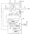
- FIG. 1 shows a configuration diagram of an embodiment of a respiratory impedance measuring apparatus according to the present invention.
- This respiratory impedance measuring apparatus has a tube 11 having a tip attached to the oral cavity of a person and through which a respiratory flow flows, a pressure sensor 12 that constitutes a pressure detection means that is attached to the tube 11 and detects pressure in the oral cavity, and a pressure sensor 12.
- Main components are a flow rate sensor 13 constituting flow rate detection means for detecting a flow rate due to respiration at the same position, a loudspeaker 21 constituting pressurization means for applying air vibration pressure in the oral cavity, and a computer 30.
- the output signal of the pressure sensor 12 is amplified by the amplifier 14, digitized by the A / D converter 15, and taken into the computer 30.
- the output signal of the flow sensor 13 is amplified by the amplifier 16, digitized by the A / D converter 17, and taken into the computer 30.
- the computer 30 includes a control unit 31, a Fourier transform unit 32, an extraction unit 33, and a calculation unit 34.
- the control unit 31 includes a signal input unit 35.
- the control means 31 outputs a signal for driving the loudspeaker 21 which is a pressurizing means, and generates an air vibration pressure due to an oscillation wave having only odd frequency components or even frequency components.
- the output of the control means 31 is digitized by the D / A converter 22 and sent to the driver 23.
- the driver 23 drives the loudspeaker 21, and air vibration pressure is applied to the oral cavity.
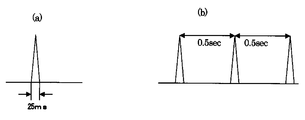
- the control means 31 generates an air vibration pressure by an oscillation wave having a frequency component of n / T (n: integer, T: real number) by applying a pulse wave having a period of T seconds ( ⁇ Frequency decimation 1>).
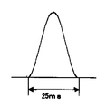
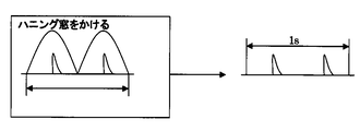
- the Hanning pulse has a base level time width of about 25 ms as shown in FIG. It is created and output in the same way as for the triangular pulse wave.
- control means 31 generates air vibration pressure by an oscillation wave having only a desired real frequency component by synthesizing a plurality of sine waves having different frequencies to give a wave obtained by the synthesis.
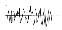
- a noise wave is output as shown in FIG.
- a noise wave having only an even frequency component is obtained by synthesizing a sine wave having an even frequency such as 2, 4, 6,..., 34 Hz.
- a noise wave having only an odd frequency component is obtained by synthesizing a sine wave having an odd frequency such as 1, 3, 5,..., 33 Hz. Noise is realized by randomizing the phase of each sine wave.
- the signal input means provided in the control means 31 is a loudspeaker so that an oscillation wave having a desired waveform becomes an output signal based on an inverse operation using an input signal and an output signal of the loudspeaker 21 and a transfer function of the loudspeaker 21. An input signal is given to the speaker 21.
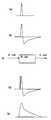
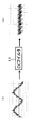
- the output signal of the loudspeaker 21 is as shown in FIG. As shown in (b), the signal has maximum points above and below the zero level. Therefore, consider a model as shown in FIG. Assuming that the transfer function of the loudspeaker 21 is H ( ⁇ ), the input signal is X ( ⁇ ), and the output signal is Y ( ⁇ ), the drive signal is obtained by obtaining x ′ (t) by inverse transformation. And
- the signal for the Hanning pulse can be similarly obtained by inverse calculation, and the loudspeaker 21 can be driven by this signal. Furthermore, it is possible to obtain a signal by a reverse operation in the same way for a sine wave, and it is also possible to obtain a noise wave by this signal synthesis.
- an instruction can be given to the computer 30 by a keyboard (not shown) or the like, and a signal waveform selected by the control means 31 according to this instruction Is output.
- the Fourier transform means 32 obtains a signal from the pressure sensor 12 and the flow sensor 13 under the pressurized condition in the oral cavity where the loudspeaker 21 is driven as described above, and Fourier-transforms the obtained signal. A spectrum is obtained.
- a CIC filter 36 is provided in the preceding stage of the Fourier transform means 32 to separate the respiration signal obtained from the pressure sensor 12 and the flow sensor 13 from the oscillation component. Further, if necessary before the processing, the Fourier transform means 32 extracts a signal through a Hanning window.
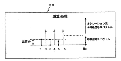
- the extraction means 33 obtains a respiratory high frequency component from the spectrum corresponding to the frequency component thinned out from the conversion result by the Fourier transform means 32, and subtracts it from the spectrum corresponding to the frequency component left by the thinning to extract the oscillation wave component.
- the respiratory high frequency component is obtained from the spectrum obtained by the Fourier transform means 32 using a spectrum corresponding to other frequencies excluding the frequency component of n / T (n: integer), and the frequency remaining by decimation.
- the oscillation wave component is extracted by subtracting from the spectrum corresponding to the component (frequency component of n / T).
- the extraction means 33 is a frequency component different from the frequency component (here, even frequency component or odd frequency component) given to the loudspeaker 21 for the spectrum obtained by the Fourier transform means 32.
- a high-frequency respiratory component is obtained from a spectrum corresponding to (odd frequency component or even frequency component) and subtracted from the spectrum corresponding to the frequency component applied to the loudspeaker 21 to extract the oscillation wave component.
- the calculating means 34 calculates the respiratory impedance by dividing the pressure component by the flow rate component for each frequency of the extraction result by the extracting means 33. That is, the respiratory impedance is Z ( ⁇ ), the oscillation wave component of the intraoral pressure is P ( ⁇ ), the oscillation wave component of the flow rate is F ( ⁇ ), and the respiratory impedance is Z ( ⁇ ) is the resistance component R ( ⁇ ) And the reactance component X ( ⁇ ), the respiratory impedance Z ( ⁇ ) is obtained by the following equation.
- the respiration impedance Z ( ⁇ ) obtained by the computing means 34 is output to the display unit 40 as a display signal for the display unit 40 such as an LCD connected to the computer 30 for display.
- the control means 31 and the signal input means 35 drive the speaker 21 with a T-second cycle (for example, at intervals of 0.5 seconds) by the inversely calculated waveform.
- the waveforms of the signals obtained by the pressure sensor 12 and the flow sensor 13 are both waveforms in which a triangular pulse wave is superimposed on the respiratory signal, as shown in FIG. And the respiratory wave and the oscillation wave (triangular pulse wave) are separated.
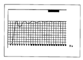
- FIG. 7 shows the frequency characteristics of the CIC filter 36. Separation can be performed by the CIC filter 36 without changing the phase. However, since the respiration signal contains a high frequency component (the same frequency band as the oscillation signal), it cannot be completely separated.
- each pulse from which a T-second interval is extracted is processed by a Hanning window to extract the pulse.
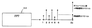
- a Fourier transform is performed by the Fourier transform means 32 to obtain a spectrum.
- the spectrum of odd frequencies 1, 3, 5,. Is a respiratory signal spectrum that does not include an oscillation wave component.
- the spectrum of the even frequency of 2, 4, 6,... Corresponding to the frequency components remaining after thinning includes an oscillation wave component and a respiratory signal component.
- the extracting means 33 subtracts the noise component estimated from the odd frequency spectrum from the even frequency spectrum to extract the oscillation wave component.
- the processing by the extraction means 33 removes a high-frequency respiratory signal of 3 Hz or more, which has been conventionally not included in the respiratory signal, and enables highly accurate measurement of respiratory impedance.
- the calculation means 34 calculates the respiratory impedance by dividing the pressure component by the flow rate component as shown by the expression (2) for each frequency of the extraction result by the extraction means 33.
- a display signal of the calculated respiratory impedance is created and output to the display unit 40 for display.
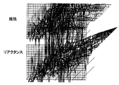
- FIG. 11 shows the respiratory impedance measured and displayed in this way.
- FIG. 12 shows the respiratory impedance when the respiratory high-frequency signal is not removed.
- the horizontal axis is a frequency axis with a scale of 1 Hz
- the vertical axis is impedance.
- the diagonal axis is the time axis
- the pure resistance component is displayed on the upper side of the diagram
- the reactance component is displayed on the lower side of the diagram.
- new impedance displays appear one after another, and the impedance is continuously measured.
- FIGS. 11 and 12 it is understood that noise is removed and highly accurate respiratory impedance measurement is possible.
- the components remaining after subtraction are the components of even frequencies of 2, 4, 6,... Corresponding to the frequency components remaining after thinning, and correspond to the thinned frequency components. There are no odd frequency components of 1, 3, 5,. Therefore, the calculation means 34 performs an interpolation process, and it is possible to measure the respiratory impedance even for components that do not exist.
- the loudspeaker 21 is driven by the control unit 31 and the signal input unit 35 with the noise wave having only the even frequency component of the synthesized waveform.
- the waveforms of the signals obtained by the pressure sensor 12 and the flow sensor 13 are both waveforms in which a noise wave is superimposed on the respiratory signal, as shown in FIG.
- the respiratory wave and the oscillation wave (noise wave) are separated by being passed (FIG. 13B).
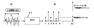
- a section of 1 second is extracted from the oscillation wave and used for signal processing. That is, as shown in FIG. 14B, a spectrum is obtained by performing a Fourier transform by the Fourier transform means 32 on the noise wave extracted from the 1 second interval.
- the loudspeaker 21 is driven by a noise wave having only even frequency components synthesized by the control means 31 and the signal input means 35.
- the spectrum of odd-numbered frequencies of 3, 5,... is a respiratory signal spectrum that does not include an oscillation wave component.
- the spectrum of the even frequency of 2, 4, 6,... Corresponding to the frequency components remaining after thinning includes an oscillation wave component and a respiratory signal component.
- the extraction means 33 subtracts the odd frequency spectrum from the even frequency spectrum to extract the oscillation wave component.
- the subsequent processing is the same as the processing in the case of using a triangular pulse wave (calculation according to FIGS. 9 and 10 and equation (2)), and a display signal of the calculated respiratory impedance is created, and the display unit 40 Is output and displayed.
- noise waves are used in this way, noise can be removed and highly accurate respiratory impedance measurement is possible, and by continuously giving noise waves, new impedance displays appear and update one after another. Thus, continuous measurement of impedance is performed.
- a display from which noise is removed is made in the same manner as shown in FIG. 11, and continuous measurement of impedance is possible.
- the calculation means 34 creates an image for display on the display device and displays it, thereby realizing a respiratory impedance display method. That is, the calculation means 34 determines the coordinates of the respiratory impedance calculated by itself so that, for example, each frequency takes a value from the back side to the near side of the screen, takes out the resistance component Rrs for each frequency, and displays it. Plotting is performed in the height direction on the screen of the apparatus, and the three-dimensional image as shown in FIG. That is, the display is performed by taking values in three dimensions by the impedance axis, the frequency axis, and the time axis.
- an image is created and displayed when the respiratory impedance obtained by performing interpolation processing on the thinned frequencies is displayed in three dimensions. For example, when an odd frequency is thinned out, two impedance values corresponding to an even frequency adjacent to the thinned odd number are obtained. Therefore, an average of the two impedance values is obtained and the frequency corresponding to the thinned out frequency is obtained. Impedance value. In this way, since the result of the interpolation processing is also displayed as an image, changes in the impedance value are displayed finely and smoothly, and it becomes possible to appropriately grasp the impedance for the entire frequency.
- the sampling time is 0.5 seconds, and as shown in FIG. 15B, the length in the time axis direction is set to a length that repeats at least two pairs of exhaled air and inhaled air, and an image is created and displayed. Do. In the example of FIG. 15, the length is set to repeat three sets of exhalation and inspiration.
- the resistance value Rrs is colored by the color scale shown at the bottom of FIG. 15, and an image is created and displayed.
- the subject Since the image obtained by each of the above processes is displayed, the subject only repeats exhalation and inhalation, and the images as shown in FIG. 15 are automatically created and displayed in time series. It can be visually observed as an image expressed by a change in color or a change in shading, including a frequency-corresponding portion obtained by thinning out a change in respiratory impedance.
- % FEV1 of FIG.15 (b) is a value which shows what% of forced vital capacity could be called in 1 second. Therefore, this example shows whether 24.4% could be called in 1 second.
- the block diagram of the respiratory impedance measuring apparatus which concerns on the Example of this invention The figure which shows an example of the triangular pulse wave which is an oscillation wave used for the respiratory impedance measuring apparatus which concerns on the Example of this invention.
- requiring respiratory impedance using the triangular pulse wave which is an oscillation wave with the respiratory impedance measuring apparatus which concerns on the Example of this invention The figure which shows the frequency characteristic of the filter employ
- requiring respiratory impedance using the triangular pulse wave which is an oscillation wave with the respiratory impedance measuring apparatus which concerns on the Example of this invention The figure which shows the respiratory impedance obtained by the respiratory impedance measuring apparatus which concerns on the Example of this invention. The figure which shows the respiratory impedance obtained by the respiratory impedance measuring apparatus which does not use the method of this invention.
Landscapes
- Health & Medical Sciences (AREA)
- Life Sciences & Earth Sciences (AREA)
- Physics & Mathematics (AREA)
- Engineering & Computer Science (AREA)
- Molecular Biology (AREA)
- Animal Behavior & Ethology (AREA)
- Veterinary Medicine (AREA)
- Public Health (AREA)
- General Health & Medical Sciences (AREA)
- Surgery (AREA)
- Biophysics (AREA)
- Pathology (AREA)
- Biomedical Technology (AREA)
- Heart & Thoracic Surgery (AREA)
- Medical Informatics (AREA)
- Physiology (AREA)
- Pulmonology (AREA)
- Mathematical Physics (AREA)
- Artificial Intelligence (AREA)
- Computer Vision & Pattern Recognition (AREA)
- Signal Processing (AREA)
- Psychiatry (AREA)
- Measurement Of The Respiration, Hearing Ability, Form, And Blood Characteristics Of Living Organisms (AREA)
Abstract
Description


12 圧力センサ
13 流量センサ
21 ラウドスピーカ
30 コンピュータ
31 制御手段
32 フーリエ変換手段
33 抽出手段
34 演算手段
35 信号入力手段
36 CICフィルタ
40 表示部
Claims (13)
- 口腔内に空気振動圧を加えるための加圧手段と、
この加圧手段を駆動する信号であって、複数の異なる周波数から間引きして残った周波数成分のみを有するように周波数間引きされた信号であるオシレーション波による空気振動圧を生じさせる制御手段と、
口腔内の圧力を検出する圧力検出手段と、
呼吸による流量を検出する流量検出手段と、
前記加圧手段による加圧状態下において前記圧力検出手段と前記流量検出手段により得られる信号を得て、この得られた信号をフーリエ変換してスペクトルを得るフーリエ変換手段と、
このフーリエ変換手段による変換結果について間引きした周波数成分対応のスペクトルにより呼吸高周波成分を求め、間引きにより残った周波数成分対応のスペクトルから減算してオシレーション波成分を取り出す抽出手段と、
この抽出手段による抽出結果について周波数毎に圧力成分を流量成分で除算する演算手段と
を具備することを特徴とする呼吸インピーダンス測定装置。 - 制御手段は周波数間引きとして、周期Tのパルス波を与えることにより、n/T(n:整数、T:実数)の周波数成分のみを有するオシレーション波による空気振動圧を生じさせることを特徴とする請求項1に記載の呼吸インピーダンス測定装置。
- 制御手段は、異なる複数周波数の正弦波を複数合成することにより、周波数間引きされたオシレーション波を得て当該シレーション波による空気振動圧を生じさせること特徴とする請求項1に記載の呼吸インピーダンス測定装置。
- 制御手段は、加圧手段の入力信号と出力信号及び前記加圧手段の伝達関数を用いた逆演算に基づき所望の圧波形のオシレーション波が出力信号となるように前記加圧手段へ入力信号を与える信号入力手段を具備することを特徴とする請求項1乃至3のいずれか1項に記載の呼吸インピーダンス測定装置。
- 信号入力手段は、逆演算により得られた信号の各周波数成分に一定の値を加えるか、前記出力信号のオンセット部分にインパルスを加えた信号を逆演算して、得られた信号を前記加圧手段へ入力信号を与えることを特徴とする請求項4に記載の呼吸インピーダンス測定装置。
- 口腔内に空気振動圧を加えるための加圧ステップと、
この加圧ステップを制御し、複数の異なる周波数から間引きして残った複数の周波数成分のみを有するように周波数間引きされた信号であるオシレーション波による空気振動圧を生じさせる制御ステップと、
口腔内の圧力を検出する圧力検出ステップと、
呼吸による流量を検出する流量検出ステップと、
前記加圧ステップによる加圧状態下において前記圧力検出ステップと前記流量検出ステップにより得られる信号を得て、この得られた信号をフーリエ変換して得られるスペクトルを得るフーリエ変換ステップと、
このフーリエ変換ステップによる変換結果について間引きした周波数成分対応のスペクトルにより呼吸高周波成分を求め、間引きして残った周波数成分対応のスペクトルからこの呼吸高周波成分を減算してオシレーション波成分を取り出す抽出ステップと、
この抽出ステップによる抽出結果について周波数毎に圧力成分を流量成分で除算する演算ステップと
を具備し、前記各ステップをコンピュータ処理・制御において実行することを特徴とする呼吸インピーダンス測定方法。 - 制御ステップは周波数間引きとして、T周期のパルスを与えることにより、n/T(n:整数T:実数)の周波数成分のみを有するオシレーション波による空気振動圧を生じさせることを特徴とする請求項6に記載の呼吸インピーダンス測定方法。
- 制御ステップは、異なる複数周波数の正弦波を複数合成することにより、周波数間引きされたオシレーション波を得て当該シレーション波による空気振動圧を生じさせること特徴とする請求項6に記載の呼吸インピーダンス測定方法。
- 制御ステップは、加圧ステップの入力信号と出力信号及び前記加圧ステップの伝達関数を用いた逆演算に基づき所望の圧波形のオシレーション波が出力信号となるように前記加圧ステップへ入力信号を与える信号入力ステップを具備することを特徴とする請求項6乃至8のいずれか1項に記載の呼吸インピーダンス測定方法。
- 信号入力ステップは、逆演算により得られた信号の各周波数成分に一定の値を加えるか、前記出力信号のオンセット部分にインパルスを加えた信号を逆演算して、得られた信号を前記加圧ステップへ与えることを特徴とする請求項9に記載の呼吸インピーダンス測定方法。
- 呼吸インピーダンス測定装置により測定された呼吸インピーダンスに基づき表示装置に表示を行う呼吸インピーダンス表示方法において、
インピーダンス軸と周波数軸と時間軸とにより三次元に値をとって表示を行い、
間引かれた周波数について補間処理を行って得られる呼吸インピーダンスを前記三次元に値をとって表示する場合に含めた画像を作成して表示を行うことを特徴とする呼吸インピーダンス表示方法。 - 時間軸方向の長さを、呼気と吸気との組を少なくとも二組繰り返す長さとして、画像を作成して表示を行うことを特徴とする請求項11に記載の呼吸インピーダンス表示方法。
- インピーダンス値の大小を、色の変化または濃淡変化により表現した画像を作成して表示を行うことを特徴とする請求項11または12に記載の呼吸インピーダンス表示方法。
Priority Applications (5)
| Application Number | Priority Date | Filing Date | Title |
|---|---|---|---|
| KR1020107020093A KR101184657B1 (ko) | 2008-03-10 | 2009-03-09 | 호흡임피던스 측정장치 및 그 측정방법, 호흡임피던스 표시방법 |
| EP09719205.8A EP2253268B1 (en) | 2008-03-10 | 2009-03-09 | Respiration impedance measuring device and method, and respiration impedance display method |
| CA2717318A CA2717318C (en) | 2008-03-10 | 2009-03-09 | Respiratory impedance measuring apparatus and method and respiratory impedance display method |
| CN200980108179XA CN101959455B (zh) | 2008-03-10 | 2009-03-09 | 呼吸阻抗测量装置及其测量方法、呼吸阻抗显示方法 |
| US12/922,024 US20110060237A1 (en) | 2008-03-10 | 2009-03-09 | Respiration impedance measuring device and method, and respiration impedance display method |
Applications Claiming Priority (4)
| Application Number | Priority Date | Filing Date | Title |
|---|---|---|---|
| JP2008-060002 | 2008-03-10 | ||
| JP2008060002 | 2008-03-10 | ||
| JP2008160042A JP5198162B2 (ja) | 2008-03-10 | 2008-06-19 | 呼吸インピーダンス測定装置及びその測定方法 |
| JP2008-160042 | 2008-06-19 |
Publications (1)
| Publication Number | Publication Date |
|---|---|
| WO2009113500A1 true WO2009113500A1 (ja) | 2009-09-17 |
Family
ID=41065167
Family Applications (1)
| Application Number | Title | Priority Date | Filing Date |
|---|---|---|---|
| PCT/JP2009/054441 Ceased WO2009113500A1 (ja) | 2008-03-10 | 2009-03-09 | 呼吸インピーダンス測定装置及びその測定方法、呼吸インピーダンス表示方法 |
Country Status (7)
| Country | Link |
|---|---|
| US (1) | US20110060237A1 (ja) |
| EP (1) | EP2253268B1 (ja) |
| JP (1) | JP5198162B2 (ja) |
| KR (1) | KR101184657B1 (ja) |
| CN (1) | CN101959455B (ja) |
| CA (1) | CA2717318C (ja) |
| WO (1) | WO2009113500A1 (ja) |
Cited By (3)
| Publication number | Priority date | Publication date | Assignee | Title |
|---|---|---|---|---|
| EP2384697A1 (en) * | 2010-05-05 | 2011-11-09 | Universiteit Gent | Method and device for determining non-linear effects in the respiratory impedance |
| RU2606107C2 (ru) * | 2009-12-03 | 2017-01-10 | Конинклейке Филипс Электроникс Н.В. | Способ и устройство для оценки дыхательного импеданса |
| US20220313939A1 (en) * | 2018-07-05 | 2022-10-06 | Hill-Rom Services Pte. Ltd. | Apparatus and method to assess airway clearance therapy efficacy |
Families Citing this family (25)
| Publication number | Priority date | Publication date | Assignee | Title |
|---|---|---|---|---|
| WO2010119843A1 (ja) * | 2009-04-13 | 2010-10-21 | チェスト株式会社 | 呼吸インピーダンス測定装置及び呼吸インピーダンス表示方法 |
| US11723542B2 (en) | 2010-08-13 | 2023-08-15 | Respiratory Motion, Inc. | Advanced respiratory monitor and system |
| KR101805078B1 (ko) * | 2010-08-13 | 2018-01-10 | 레스퍼러토리 모션 인코포레이티드 | 호흡량, 운동 및 가변성 측정에 의한 호흡 변화 모니터링 장치 및 방법 |
| US10702166B1 (en) | 2010-08-13 | 2020-07-07 | Respiratory Motion, Inc. | Devices and methods for respiratory variation monitoring by measurement of respiratory volumes, motion and variability |
| CN102488521A (zh) * | 2011-12-09 | 2012-06-13 | 东莞理工学院 | 医用呼吸监测仪呼吸阻力值计算装置 |
| US12343130B2 (en) | 2012-09-07 | 2025-07-01 | Respiratory Motion, Inc. | Spacing of electrodes for bioimpedance measurements |
| CA2883623C (en) | 2012-09-07 | 2020-06-23 | Respiratory Motion, Inc. | Electrode padset |
| US9955918B2 (en) * | 2012-12-31 | 2018-05-01 | University of Alaska Anchorage | Mouth guard for determining physiological conditions of a subject and systems and methods for using same |
| US10028679B2 (en) | 2012-12-31 | 2018-07-24 | University of Alaska Anchorage | Devices, systems, and methods for determining linear and angular accelerations of the head |
| CN103285479B (zh) * | 2013-06-08 | 2015-05-06 | 首都医科大学附属北京朝阳医院 | 一种呼吸机气道陷闭特征参数的监测装置 |
| ES2827309T3 (es) | 2014-03-06 | 2021-05-20 | Respiratory Motion Inc | Métodos y dispositivos para la visualización de tendencias y variabilidad en una serie de datos fisiológicos |
| JP2017537753A (ja) | 2014-11-04 | 2017-12-21 | レスピラトリー・モーション・インコーポレイテッド | 呼吸パラメータによって誘導される自動静脈内投与および静脈内チューブクランプアクティブ化 |
| CN104473647A (zh) * | 2014-12-12 | 2015-04-01 | 温州医科大学 | 一种无线强迫振荡肺阻抗测试仪及其测试方法 |
| JP2019504665A (ja) | 2015-12-15 | 2019-02-21 | レスピラトリー・モーション・インコーポレイテッド | パルスオキシメトリ前の呼吸困難を検出するための呼吸量モニタリングの評価および虚偽の不飽和化警報の除去 |
| US11357421B2 (en) | 2016-02-03 | 2022-06-14 | Cognita Labs, LLC | Forced oscillation technique based lung function testing |
| CN106073783B (zh) * | 2016-06-23 | 2024-02-20 | 桂林航天工业学院 | 一种从光电容积脉搏波中提取呼吸率的方法 |
| CN108652632B (zh) * | 2017-03-31 | 2023-07-14 | 中国人民解放军总医院 | 强迫振荡肺功能测试装置及方法 |
| US11433202B2 (en) * | 2017-12-18 | 2022-09-06 | Koninklijke Philips N.V. | Interactive guidance related to a subject's expiratory flow limitation results |
| JP7045073B2 (ja) * | 2019-02-15 | 2022-03-31 | チェスト株式会社 | 呼吸抵抗測定装置及び表示制御方法 |
| JP7054929B2 (ja) * | 2019-02-15 | 2022-04-15 | チェスト株式会社 | 呼吸抵抗測定装置及び検査結果予測方法 |
| WO2020247940A1 (en) | 2019-06-07 | 2020-12-10 | Respiratory Motion, Inc. | Device and method for clinical evaluation |
| DE102020118529A1 (de) * | 2020-07-14 | 2022-01-20 | Ventinova Technologies B.V. | Beatmungsvorrichtung und Verfahren zur Bestimmung zumindest eines alveolären Druckes bzw. eines Verlaufs eines alveolären Druckes in einem Atemweg eines Patienten |
| CN115702786B (zh) * | 2021-08-11 | 2026-01-13 | 深圳市美好创亿医疗科技股份有限公司 | 一种呼吸阻抗检测方法及检测系统 |
| CN119212615A (zh) * | 2022-07-12 | 2024-12-27 | 深圳麦科田生物医疗技术股份有限公司 | 呼吸阻抗测量系统及呼吸阻抗测量方法 |
| CN120884277B (zh) * | 2025-10-09 | 2025-11-28 | 中国科学院合肥物质科学研究院 | 一种基于呼吸阻抗模型的呼吸功率检测方法与系统 |
Citations (3)
| Publication number | Priority date | Publication date | Assignee | Title |
|---|---|---|---|---|
| JPS4934185A (ja) * | 1972-07-31 | 1974-03-29 | ||
| JPH0339140A (ja) | 1989-07-06 | 1991-02-20 | Chiesuto Kk | 呼吸抵抗測定装置 |
| JP2007536026A (ja) * | 2004-05-04 | 2007-12-13 | ダルハウジー ユニバーシティー | 気道の反応性亢進における気道の変動性を評価する方法 |
Family Cites Families (5)
| Publication number | Priority date | Publication date | Assignee | Title |
|---|---|---|---|---|
| US6142952A (en) * | 1997-10-29 | 2000-11-07 | The Board Of Regents, The University Of Texas System | Method and apparatus for detection and diagnosis of airway obstruction degree |
| US6435182B1 (en) * | 1999-03-24 | 2002-08-20 | Trustees Of Boston University | Enhanced ventilation waveform device |
| US6443907B1 (en) * | 2000-10-06 | 2002-09-03 | Biomedical Acoustic Research, Inc. | Acoustic detection of respiratory conditions |
| JP2010501291A (ja) * | 2006-08-30 | 2010-01-21 | レスメド・リミテッド | 複素アドミッタンス値による、呼吸気道の閉塞性および開放性無呼吸の識別 |
| US8100836B2 (en) * | 2006-12-06 | 2012-01-24 | Texas Christian University | Augmented RIC model of respiratory systems |
-
2008
- 2008-06-19 JP JP2008160042A patent/JP5198162B2/ja active Active
-
2009
- 2009-03-09 EP EP09719205.8A patent/EP2253268B1/en active Active
- 2009-03-09 WO PCT/JP2009/054441 patent/WO2009113500A1/ja not_active Ceased
- 2009-03-09 KR KR1020107020093A patent/KR101184657B1/ko not_active Expired - Fee Related
- 2009-03-09 US US12/922,024 patent/US20110060237A1/en not_active Abandoned
- 2009-03-09 CA CA2717318A patent/CA2717318C/en active Active
- 2009-03-09 CN CN200980108179XA patent/CN101959455B/zh active Active
Patent Citations (3)
| Publication number | Priority date | Publication date | Assignee | Title |
|---|---|---|---|---|
| JPS4934185A (ja) * | 1972-07-31 | 1974-03-29 | ||
| JPH0339140A (ja) | 1989-07-06 | 1991-02-20 | Chiesuto Kk | 呼吸抵抗測定装置 |
| JP2007536026A (ja) * | 2004-05-04 | 2007-12-13 | ダルハウジー ユニバーシティー | 気道の反応性亢進における気道の変動性を評価する方法 |
Non-Patent Citations (4)
| Title |
|---|
| HAJIME KUROSAWA: "COPD no Shindan to Hai Kino Kensa no Shinpo", KAGAKU RYOHO NO RYOIKI, vol. 21, 11 May 2005 (2005-05-11), pages 74 - 80, 252 * |
| HIROMASA OGAWA: "Kokyu Kino Kensa -Impulse Oscillometry-ho", KOKYU TO JUNKAN, vol. 54, no. 6, 15 June 2006 (2006-06-15), pages 615 - 622, 678, XP008140633 * |
| See also references of EP2253268A4 * |
| TOYOHIRO HIRAI: "IOS-ho ni yoru Kokyu Teiko no Hyoka", KOKYU TO JUNKAN, vol. 51, no. 12, December 2003 (2003-12-01), pages 1241 - 1244, XP008140628 * |
Cited By (4)
| Publication number | Priority date | Publication date | Assignee | Title |
|---|---|---|---|---|
| RU2606107C2 (ru) * | 2009-12-03 | 2017-01-10 | Конинклейке Филипс Электроникс Н.В. | Способ и устройство для оценки дыхательного импеданса |
| EP2384697A1 (en) * | 2010-05-05 | 2011-11-09 | Universiteit Gent | Method and device for determining non-linear effects in the respiratory impedance |
| US20220313939A1 (en) * | 2018-07-05 | 2022-10-06 | Hill-Rom Services Pte. Ltd. | Apparatus and method to assess airway clearance therapy efficacy |
| US12186487B2 (en) * | 2018-07-05 | 2025-01-07 | Hill-Rom Services Pte. Ltd. | Apparatus and method to assess airway clearance therapy efficacy |
Also Published As
| Publication number | Publication date |
|---|---|
| CA2717318A1 (en) | 2009-09-17 |
| KR20100120204A (ko) | 2010-11-12 |
| JP5198162B2 (ja) | 2013-05-15 |
| CA2717318C (en) | 2015-04-21 |
| CN101959455A (zh) | 2011-01-26 |
| JP2009240752A (ja) | 2009-10-22 |
| EP2253268B1 (en) | 2014-08-27 |
| EP2253268A4 (en) | 2012-06-06 |
| KR101184657B1 (ko) | 2012-09-20 |
| EP2253268A1 (en) | 2010-11-24 |
| US20110060237A1 (en) | 2011-03-10 |
| CN101959455B (zh) | 2013-03-13 |
Similar Documents
| Publication | Publication Date | Title |
|---|---|---|
| JP5198162B2 (ja) | 呼吸インピーダンス測定装置及びその測定方法 | |
| JP5583454B2 (ja) | 呼吸インピーダンス測定装置及び呼吸インピーダンス表示方法 | |
| JP6049889B2 (ja) | 嚥下推定装置 | |
| JP2005066045A (ja) | 音データ処理装置及びプログラム | |
| US11246526B2 (en) | Swallowing diagnosis apparatus and storage medium | |
| JP6467044B2 (ja) | シャント音解析装置、シャント音解析方法、コンピュータプログラム及び記録媒体 | |
| JP2005066044A (ja) | 呼吸音データ処理装置及びプログラム | |
| JP4310137B2 (ja) | 生体音検出データ処理装置、生体音検出データ処理方法及び生体音検出データ処理プログラム | |
| JP6298273B2 (ja) | 信号処理装置及び方法、並びにコンピュータプログラム及び記録媒体 | |
| CN108652632B (zh) | 强迫振荡肺功能测试装置及方法 | |
| JP2001104258A (ja) | 血行動態測定装置、血行動態測定方法および記録媒体 | |
| KR102242479B1 (ko) | 피부영상을 이용한 디지털 호흡 청진 방법 | |
| JP2019024619A (ja) | X線動画像解析装置及びx線動画像解析方法 | |
| JP7001806B2 (ja) | 呼吸音解析装置、呼吸音解析方法、コンピュータプログラム及び記録媒体 | |
| WO2020090763A1 (ja) | 処理装置、システム、処理方法、およびプログラム | |
| JP2019141597A (ja) | 信号処理装置及び方法、並びにコンピュータプログラム及び記録媒体 | |
| JP6031896B2 (ja) | 呼吸信号推定装置及び呼吸信号推定方法 | |
| JP2019150641A (ja) | 呼吸音解析装置 | |
| JP2016030067A (ja) | 呼吸音解析装置及び呼吸音解析方法、並びにコンピュータプログラム及び記録媒体 | |
| JP2015084849A (ja) | 信号処理装置及び方法、並びにコンピュータプログラム及び記録媒体 |
Legal Events
| Date | Code | Title | Description |
|---|---|---|---|
| WWE | Wipo information: entry into national phase |
Ref document number: 200980108179.X Country of ref document: CN |
|
| 121 | Ep: the epo has been informed by wipo that ep was designated in this application |
Ref document number: 09719205 Country of ref document: EP Kind code of ref document: A1 |
|
| WWE | Wipo information: entry into national phase |
Ref document number: 5300/CHENP/2010 Country of ref document: IN |
|
| WWE | Wipo information: entry into national phase |
Ref document number: 2717318 Country of ref document: CA |
|
| ENP | Entry into the national phase |
Ref document number: 20107020093 Country of ref document: KR Kind code of ref document: A |
|
| NENP | Non-entry into the national phase |
Ref country code: DE |
|
| WWE | Wipo information: entry into national phase |
Ref document number: 2009719205 Country of ref document: EP |
|
| WWE | Wipo information: entry into national phase |
Ref document number: 12922024 Country of ref document: US |