WO2009116362A1 - プラスチックレンズの製造方法 - Google Patents
プラスチックレンズの製造方法 Download PDFInfo
- Publication number
- WO2009116362A1 WO2009116362A1 PCT/JP2009/053257 JP2009053257W WO2009116362A1 WO 2009116362 A1 WO2009116362 A1 WO 2009116362A1 JP 2009053257 W JP2009053257 W JP 2009053257W WO 2009116362 A1 WO2009116362 A1 WO 2009116362A1
- Authority
- WO
- WIPO (PCT)
- Prior art keywords
- plastic lens
- rubbing
- lens substrate
- hard coat
- abrasive
- Prior art date
- Legal status (The legal status is an assumption and is not a legal conclusion. Google has not performed a legal analysis and makes no representation as to the accuracy of the status listed.)
- Ceased
Links
Images




Classifications
-
- B—PERFORMING OPERATIONS; TRANSPORTING
- B29—WORKING OF PLASTICS; WORKING OF SUBSTANCES IN A PLASTIC STATE IN GENERAL
- B29D—PRODUCING PARTICULAR ARTICLES FROM PLASTICS OR FROM SUBSTANCES IN A PLASTIC STATE
- B29D11/00—Producing optical elements, e.g. lenses or prisms
- B29D11/00865—Applying coatings; tinting; colouring
Definitions
- the present invention relates to a method of manufacturing a plastic lens for spectacles, and more particularly to a method of manufacturing a plastic lens including a step of forming a hard coat layer on the surface of a plastic lens substrate.
- plastic lenses are frequently used instead of glass lenses as glasses lenses. This is because the plastic lens is lighter than the glass lens, has advantages such as being hard to break and easy to process. On the other hand, the plastic lens has a disadvantage that it is easily damaged. To prevent this, a hard coat layer is formed on the surface of the plastic lens to increase the surface hardness.
- Patent Document 1 when a hard coat layer is formed on a plastic lens substrate, an abrasive is sprayed on or scratched with the surface of the lens substrate (surface to be coated) before applying the hard coat solution.
- a method of cleaning and modifying the surface has been proposed (see Patent Document 1).
- the technique described in Patent Document 1 enhances a so-called anchor effect in which a coating liquid agent enters a scratch formed on the surface of a lens substrate, and improves the adhesion between the hard coat film and the lens surface.
- Patent Document 2 a technique has been proposed in which a plasma treatment is performed on the surface of a plastic lens substrate, and then a mechanical detergent is used in combination with a neutral detergent and an abrasive to apply a hard coat layer (see Patent Document 2).
- a plasma treatment is performed on the surface of a plastic lens substrate, and then a mechanical detergent is used in combination with a neutral detergent and an abrasive to apply a hard coat layer (see Patent Document 2).
- double modification with plasma and abrasive can be performed to improve the adhesion between the hard coat layer and the lens substrate surface and prevent the hard coat layer from peeling off. I am doing so.
- Patent Document 3 a method of interposing a primer layer between the plastic lens substrate and the hard coat layer has been proposed (see Patent Document 3).
- a primer layer is interposed between the hard coat layer and the lens substrate to improve the adhesion between them.
- Patent Document 3 describes a method of rubbing the lens substrate using an abrasive composed of inorganic or organic fine particles as a method for more effectively improving the adhesion between the plastic lens substrate and the primer layer.
- the abrasive grains remain on the plastic lens surface, so it is necessary to carefully perform the cleaning treatment after the modification, and the cleaning process for that purpose Takes a lot of time. Further, depending on the shape of the particles constituting the abrasive and the amount of the abrasive used, there is a possibility that the abrasive particles are aggregated and the scratch marks are varied. If the scratch mark becomes deeper than the permissible range, the defective rate in a finished plastic lens product such as a spectacle lens will increase.
- an object of the present invention is to provide a cleaning time after the modification by modifying the surface without using an abrasive in securing the adhesion of the hard coat layer formed on the surface of the plastic lens. Is to shorten.
- a method for manufacturing a plastic lens according to the present invention includes the following steps. (1) Step of rubbing the surface of the plastic lens substrate with a wiping material (2) Step of forming a hard coat layer on the surface of the rubbing plastic lens substrate by wet surface treatment
- the present invention is the step of (1)
- the wiping material used in the above is flexible, and the wiping material is made of a material harder than the material of the lens substrate surface to be wiped, or the hard material is a flexible base material It is fixed on the top. According to such a configuration, it is possible to reliably remove the foreign matter that the hard material of the wiping material adheres to the surface of the plastic lens substrate. Further, by having flexibility, the wiping material does not generate a wiping residue, or even if it is generated, the wiping residue can be wiped off.
- Plastic lens substrate refers to the one just before the hard coat layer is formed. Therefore, it does not show only a plastic lens substrate (lens blanks) that is not subjected to any surface processing.
- a lens including a primer layer for improving adhesion of a hard coat layer and impact resistance of a plastic lens is also included in the plastic lens substrate.
- the target surface to which the wiping material is scraped in the rubbing step is the surface of the primer layer exposed to the outside before the hard coat layer is formed.
- Some plastic lenses having a light control function form a hard coat layer on the top surface of the light control layer.
- the target surface on which the wiping material is abraded in the rubbing step is the light control layer surface exposed to the outside before the hard coat layer is formed.
- the wiping material refers to a material made of a material harder than the surface material of the plastic lens substrate or having a flexibility in which the hard material is fixed on the base material.
- the “material harder than the surface material of the lens substrate” is based on the configuration of the lens substrate to be wiped, and the material can be selected depending on the material of the lens substrate outermost surface in the wiping process. For example, different materials can be selected for wiping the lens substrate on which the primer layer is formed on the surface and for rubbing the surface of the plastic lens substrate itself.
- the wiping material may be a woven fabric, a nonwoven fabric or a sponge made of a hard material, and is a so-called abrasive sheet in which hard abrasive grains are fixed to a woven fabric, a nonwoven fabric or a sponge which is a relatively soft substrate. But it ’s okay. The point is that if a hard material comes into contact with the lens substrate to be wiped, the surface contaminants can be wiped away.
- a wiping material for example, a plastic foam (sponge) which is a very fine porous body, a textured elastomer such as a plastic eraser, and a woven fabric or a non-woven fabric composed of fine threads are exemplified.
- abrasive sheets such as woven fabrics, non-woven fabrics, paper, and films in which abrasive grains of abrasives are fixed
- plastic foams and elastomers in which abrasive grains are fixed on the surface are also used as wiping materials. included.
- the present invention by rubbing the surface using such a wiping material, the contaminants that are raised on the surface of the plastic lens substrate are surely removed.
- the adhesion state of the hard coat layer due to impurities present at the adhesion interface is preferably improved.
- coloring and fogging of the finished plastic lens due to the impurities are prevented.
- secondary contamination of the plastic lens substrate occurs due to the dispersion of abrasive grains, and a great deal of labor is required to remove it, but the present invention does not use loose abrasive grains. Therefore, there is no fear of secondary contamination by abrasive grains.
- One of the preferred forms is to form a scratch mark on the surface of the plastic lens substrate in addition to removing impurities in the rubbing step.
- “Abrasion marks” refer to minute grooves. Since the interfacial area between the hard coat layer and the plastic lens substrate is ensured by the minute grooves, the adhesion due to the anchor effect is also improved.
- the refractive index of the hard coat layer is usually close to the refractive index of so-called lens blanks, which are plastic lens substrates before processing. Therefore, if the hard coat layer is formed and cured in a state where the coating liquid enters the groove, the groove is not visually recognized. According to this embodiment, the adhesion state of the interface between the hard coat layer and the plastic lens substrate is further ensured.
- One of the preferred forms further includes a step of chemically edging the plastic lens substrate.
- the order of the “chemical edging process” is not limited, and may be performed before or after the rubbing process. Moreover, it is not limited to performing continuously with a rubbing process.
- “chemical edging” refers to an edging method using an acidic solution, an alkaline solution or the like, or an edging method using an oxidizing agent or a reducing agent, and is not limited to a specific liquid agent.
- a volatile acid such as a hydrochloric acid solution, a nitric acid solution, and a perchloric acid solution in which an acid residue hardly remains after edging.
- a highly water-soluble alkaline solution such as an aqueous sodium hydroxide solution or an aqueous potassium hydroxide solution.
- the chemical edging referred to here also includes placing a plastic lens substrate in an atmosphere containing ozone.
- an alkaline aqueous solution is used as an edging agent in the chemical edging process.
- the alkaline aqueous solution can suitably modify the substrate surface and can improve the wet spreading state of the hard coat solution.
- the rubbing step is performed in a wet environment.
- the type of liquid for realizing a wet environment is not limited.
- the liquid may be any liquid as long as it can achieve wettability without altering the components constituting the surface to be abraded and without causing alteration of the wiping material used for rubbing.
- Water, an aqueous solution, an organic solvent, an organic solution, and Various mixed solutions can be appropriately selected and used.
- the present invention can be preferably applied to a plastic lens having a primer layer on at least one surface.
- the primer layer may be eroded by an alkaline solution or the like.
- the adhesion with the hard coat layer can be improved by the rubbing step.
- the time for performing chemical edging can be shortened. According to the present invention, even when a plastic lens having a primer layer is produced, the adhesion of the hard coat layer can be suitably ensured without damaging the primer layer.
- the wiping material used in the present invention is preferably a polishing sheet in which abrasive grains are fixed.
- the abrasive sheet in which the abrasive grains are fixed is a state in which the abrasive grains are fixed by an adhesive or the like on a flexible sheet such as cloth or paper in a state before the polishing process is performed. Indicates a sheet.
- abrasive sheet other than abrasive cloth paper such as abrasive paper (paper file) in which abrasive grains are fixed to paper, and abrasive cloth (cloth file) in which abrasive grains are fixed to woven or non-woven fabric.
- a polishing pad, a polishing sponge, or the like can be used.
- the particle size of the accumulated sedimentation height of 50% according to the electrical resistance test method is about 10 ⁇ m or less (so-called particle size is 1500 (# 1500) or more).
- particle size is 1500 (# 1500) or more).
- the abrasive is preferably diamond.
- Diamond is not altered or dissolved by acids, alkalis, oxidizing agents, reducing agents, and organic solvents, and when diamond abrasive grains are used, fine abrasive grains can be edged even if they are scratched immediately after chemical edging. There is an advantage that it does not react with the agent. Furthermore, since diamond is very hard, when diamond abrasive grains are employed, the abrasive grains are hardly crushed by the rubbing process. Therefore, it is difficult for a large change to occur in the shape of the scratch mark formed by each abrasive grain. For this reason, stable scratch marks can be formed.
- the wiping material is preferably a melamine resin foam (melamine foam).
- the melamine resin foam is obtained by foaming melamine, which is a hard plastic, with fine bubbles. Therefore, the hard plastic not only wipes off impurities on the surface of the lens substrate, but also can be removed in a scraped form if it adheres to the surface. Further, at this time, the scraped foreign matter is adsorbed in the foamed holes of the melamine foam, so that it can be reliably prevented from remaining as a residue on the surface of the plastic lens substrate. Furthermore, when it implements in a wet environment, the capillary phenomenon in which a liquid component is sucked up toward the foaming hole of a melamine foam arises. The foreign matter that has been scraped off and finely pulverized is collected inside the foam hole by this capillary phenomenon. As a result, it is difficult for residue of impurities to remain on the lens surface.
- the surface of the plastic lens is made uneven by rubbing the surface of the plastic lens using such a wiping material. It can suppress and modify
- the surface modification can be performed without using an abrasive to ensure the adhesion of the hard coat layer, and the cleaning process time after the surface modification can be shortened.
- the present invention is not limited to the following examples.
- the following example shows a case where the present invention is applied to a method for manufacturing a plastic lens for spectacles, the present invention can be applied to any plastic lens that forms a hard coat layer on the surface.
- FIG. 1 is a flowchart showing each step of the plastic lens manufacturing method according to the first embodiment of the present invention.
- a plastic lens substrate which is a source of spectacles
- a thiourethane lens is usually used, but in addition to this, CR39 (allyl diglycol carbonate), which is a general-purpose product and has a high refractive index, may be used. Can also be preferably applied.
- the wiping material is not particularly limited as long as it is a material capable of removing impurities adsorbed on the surface.
- a sponge-like foamed plastic material made of a hard plastic material, an abrasive sheet in which abrasive grains are fixed to a sponge, a woven fabric, a non-woven fabric, or the like can be used. By rubbing with such a wiping material, foreign substances adsorbed on the surface can be surely removed.
- a plastic foam or polishing sheet that is harder than the plastic lens base material, since the surface of the plastic lens substrate can be roughened.
- an abrasive containing free abrasive grains is not used, so that polishing abrasive grains and wiping residues (cutting pieces) remain on the surface of the plastic lens after rubbing treatment, or are almost avoided. Can do. It is also possible to avoid unexpected scratches caused by the aggregation of loose abrasive grains. That is, after the hard coat layer is formed after the rubbing treatment, it is possible to prevent the width and depth from becoming so large that the rubbing marks are visible.
- the abrasive grains have a cumulative sedimentation height 50% particle diameter of about 10 ⁇ m or less in the electrical resistance test method.
- an abrasive sheet defined by a particle size of # 1500 or more as defined in JIS “R6010” is desirable.
- an abrasive sheet such as # 1500 or more abrasive cloth or the like is used, the adhesion of the hard coat layer formed after rubbing can be reliably kept good.
- the abrasive grains are too fine to obtain the desired scratch marks, ensuring the desired adhesion. It becomes difficult.
- the polishing sheet used for the rubbing treatment it is desirable to use a particle having a 50% cumulative set height of abrasive grains having a particle size of 0.1 ⁇ m or more and 10 ⁇ m or less.
- the abrasive grains fixed to the polishing sheet include corundum (alumina), silicon carbide, boron carbide, diamond, boron nitride (CBN), cerium oxide, chromium oxide, zirconium oxide, silicon oxide, and ferric oxide.
- Various materials such as (Fe 2 O 3 , Bengala) can be used.
- abrasive grains made of a material with high hardness such as diamond, boron nitride, silicon carbide, boron carbide, corundum, etc.
- the phenomenon that the abrasive grains are crushed during rubbing and the polishing ability is reduced or the pulverized abrasive grains This is preferable because the phenomenon of being released from and adhering to the substrate is suppressed.
- a sponge-like plastic foam is used as the wiping material
- a foam made of a material harder than the plastic substrate constituting the surface to be rubbed When such a material is selected, the surface of the plastic foam can be roughened during the rubbing process.
- rigid urethane foam and melamine foam can be used for plastic lenses using polyurethane material or polycarbonate material.
- Melamine foam is preferably used for thiourethane, allyl diglycol carbonate (so-called CR39), episulfide-based resin, and the like, which are relatively hard plastic materials.
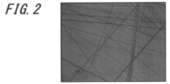
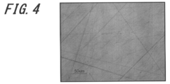
- FIGS. 2 to 4 show the results of microscopic observation of a plastic lens substrate wet-rubbed by a human hand using polishing sheets on which abrasive grains of different particle sizes are fixed.
- FIG. 2 shows the surface of a thiourethane lens substrate (refractive index ne: 1.67, manufactured by HOYA, trade name: Ainoa (hereinafter referred to as “thiourethane lens substrate”)) with a brushed woven cloth and diamond abrasive
- a micrograph is shown when the diamond abrasive cloth (Noritake Coated Abrasive Co., Ltd., trade name: diamond abrasive cloth (hereinafter simply referred to as “diamond abrasive cloth”)) # 1500 is used to grind the grains.
- FIG. 3 shows a photomicrograph when the surface of the thiourethane-based lens substrate is rubbed with diamond polishing cloth # 3000.
- FIG. 4 shows a photomicrograph when the surface of the thiourethane-based lens substrate is rubbed with diamond polishing cloth # 6000.
- FIG. 5 shows a photomicrograph when the surface of the thiourethane lens substrate is rubbed with melamine foam (manufactured by Lec Co., Ltd.). 2 to 5, the line segment shown in the lower left part has a length of 50 ⁇ m.
- step S3 the plastic lens substrate after the rubbing treatment is subjected to surface purification treatment by ultrasonic cleaning or the like. Thereafter, the plastic lens substrate is dipped in a hard coat solution as described later to form a hard coat layer on the plastic lens substrate (step S4).
- a surface purification process is provided as step S3, but this purification process is not necessarily required. Even when a surface purification step is provided, in the present invention, as described above, the remaining abrasive grains can be almost avoided or sufficiently suppressed, and therefore the purification time can be shortened.
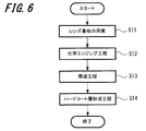
- FIG. 6 is a flowchart showing a plastic lens manufacturing method according to the second embodiment of the present invention.
- the manufacturing method shown in FIG. 6 is different from the manufacturing method shown in FIG. 1 in that a chemical edging process such as an alkaline solution cleaning is included before the rubbing process, and a surface cleaning process after the rubbing process is omitted.
- a chemical edging process such as an alkaline solution cleaning
- a surface cleaning process after the rubbing process is omitted.
- a lens substrate is prepared (step S11), and processing with a chemical edging reagent is performed (step S12).
- a hard coat layer forming step is performed (step S14) through a rubbing step with a polishing sheet (step S13).
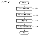
- FIG. 7 is a flowchart showing a plastic lens manufacturing method according to the third embodiment of the present invention.
- the manufacturing method shown in FIG. 7 is different from the manufacturing method shown in FIG. 1 in that it includes a step (step 22) of forming a primer layer before the rubbing step (step 23), and a surface purification treatment after the rubbing step. It is a place to omit. Further, the difference from the manufacturing method shown in FIG. 6 is that a primer layer is formed before the rubbing step and that the chemical edging treatment is omitted.
- the present invention can ensure adhesion of the hard coat layer only by rubbing without performing chemical edging such as alkali cleaning as described above, when forming a primer layer in this way,
- the material of the primer layer is not limited to a material having chemical stability such as alkali resistance.
- the primer layer material is required to be a material that can maintain impact resistance and adhesion even when an edging reagent is attached. There is no need to consider such characteristics, and the degree of freedom in selecting the primer layer material can be increased.
- FIG. 8 is a flowchart showing a plastic lens manufacturing method according to the fourth embodiment of the present invention.
- the chemical edging process (step 12) of the manufacturing method shown in FIG. 6 is performed after the rubbing step (step 13).
- the chemical edging reagent is washed away after completion of the rubbing step (physical edging) in step S13, so that even if a rubbing residue or the like adheres to the surface, it can be reliably washed.
- the abrasive sheet used as the wiping material was a cloth file, and it was confirmed that the rubbing treatment (Example 1) exhibited the same effect as the rubbing treatment (Comparative Example 1) when an abrasive was used. Moreover, the case where the rubbing process was not performed (Comparative Example 2) was also confirmed.
- Example 1 In this example, the processing shown in the flowchart of FIG. 1 was performed to form a hard coat layer on the plastic lens. In the rubbing process, samples (samples 1 to 4) using a # 1500 cloth file and samples (samples 5 to 8) using melamine foam were prepared. A lens substrate made of the same material was subjected to the same treatment to form a hard coat layer, and the adhesion was evaluated.
- a thiourethane lens substrate (refractive index ne: 1.67, manufactured by HOYA, trade name: Ainoa) was prepared.
- a wiping material Noritake Coated Abrasive Co., Ltd., trade name: Diamond abrasive cloth paper, # 1500 was used to wipe the four substrates (samples 1 to 4), and the wiping material
- the other four substrates (samples 5 to 8) were subjected to a rubbing treatment using a melamine foam manufactured by Lec Co., Ltd. At this time, the rubbing treatment was performed in a flowing water environment.
- the plastic lens substrate 2 was first rubbed 10 times in one direction as indicated by an arrow m. Thereafter, the plastic lens substrate 2 was rotated 90 degrees, and as indicated by an arrow n, the plastic lens substrate 2 was further rubbed 10 times in a direction substantially perpendicular to the rub marks 5 caused by the above-mentioned rub.
- the load at the time of rubbing was in the range of 300G to 400G
- the load at the time of rubbing was in the range of 750G to 800G.
- step S3 the substrate surface was wiped off with a cloth holding acetone, and then subjected to a surface purification treatment for 300 seconds using ion-exchanged water under application of ultrasonic waves of 28 kHz. After ultrasonic cleaning, it was dried in an atmosphere at 70 ° C.
- step S4 the hard coat layer forming step.
- a plastic lens substrate was immersed in a hard coat composition solution for 30 seconds by a dipping method.
- the plastic substrate immersed in the hard coat composition liquid was pulled up at a speed of 30 cm / min.
- the pulled plastic lens substrate was heated at a temperature of 110 ° C. for 60 minutes to cure the hard coat liquid and form a hard coat layer.
- the refractive index (ne) of the hard coat layer thus formed was 1.65.
- DAA diacetone alcohol
- propylene propylene were stirred while stirring 180 parts by mass of a separately prepared modified zirconium oxide-stannic oxide composite methanol sol (manufactured by Nissan Chemical Industries, Ltd.) in an atmosphere of 5 ° C. 80 parts by mass of glycol monomethyl ether (PGM) was mixed. Then, while stirring this mixture, 62.5 parts by mass of a modified titanium oxide-tin oxide-silicon oxide-zirconium oxide composite methanol sol (catalyst chemical industry Co., Ltd., trade name: OPTRAIQUE 1120Z) was further mixed, Stir for 1 hour.
- DAA diacetone alcohol
- PGM glycol monomethyl ether
- silane coupling agent was added dropwise with stirring and stirred for a whole day and night.
- 0.25 parts by mass of a silicon-based surfactant (trade name: Y-7006, manufactured by Toray Dow Corning Co., Ltd.) and 5 parts by mass of aluminum trisacetylacetonate were sequentially added and stirred for 150 hours.
- a solution obtained by filtering the obtained solution through a 0.5 ⁇ m filter was used as a coating composition.
- the hard coat composition has a proportion of fine particles of inorganic compounds such as tin oxide, zirconium oxide, silicon oxide, and titanium oxide of about 20%, and a silane coupling agent ( ⁇ -glycidoxypropyltrimethoxysilane).
- a solution containing about 20% of an alcohol solvent such as methanol, 1-methoxy-2-propanol, 4-hydroxy-4-methyl-2-pentanone is used. The remaining approximately 5% is leveling agents and other additives.
- Comparative Example 1 In Comparative Example 1, a sponge holding an abrasive (manufactured by Fujimi Incorporated, trade name: POLIPLA 103H) was used in the rubbing step (step S2).
- the conditions of the rubbing treatment (the rubbing direction and the number of rubbing, the load at the time of rubbing) are the same as the sample No. 1 in Example 1 described above. The same as 1 to 4.
- the other surface purification treatment step (Step S3) and the hard coat layer formation step (Step S4) were also the same as in Example 1.
- Four lenses were produced by this method, and the adhesion between the hard coat layer and the plastic lens substrate was confirmed by a test under the same conditions as in Example 1. The results are shown in Sample No. 1 of Comparative Example 1. 1 to 4 are shown in Table 1 above.
- Comparative Example 2 In Comparative Example 2, the surface purification treatment (Step S3) and the hard coat layer forming step (Step S4) were performed under the same conditions as in Example 1 except that the rubbing step (Step S2) was omitted. Five lenses were produced by this method, and the adhesion was similarly confirmed by a test. The results are shown in Sample No. 2 of Comparative Example 2. 1 to 5 are shown in Table 1 above.
- FIG. 10 is a front view and a side view of the plastic lens 1 manufactured by the manufacturing method described above.
- the plastic lens 1 is configured by forming a hard coat layer 3 on the entire surface of a plastic lens substrate 2.
- the hard coat layer 3 may be a simple cured film, but can also serve as an antireflection film.
- the hard coat layer 3 is shown thick for easy understanding, but it is actually a film of about 2 to 5 ⁇ m.
- one lens sample is applied to the hard coat layer 3 (cured film or antireflection film) formed on the surface of the plastic lens 1.
- the hard coat layer 3 cured film or antireflection film
- 100 cross cuts 4 were formed with a razor.
- an adhesive tape the Nichiban Co., Ltd. cello tape (trademark)
- Examined. Evaluation is based on the number of areas where no peeling occurs in 100 eyes. That is, when the number is 100, no peeling occurs.
- what peeled partially in 1 eye evaluated the degree by the area ratio below a decimal point. For example, in the case of 1 out of 100 eyes, when film peeling occurs in about 1/10 of the area, it is shown in the table as 99.9.
- the particle size of the fine powder for abrasive (abrasive grains) measured by the electrical resistance test method in the case of # 1500 abrasive cloth, the particle diameter of 50% cumulative sedimentation height Is defined as “9.7 ⁇ 0.8 ⁇ m”.
- the electrical resistance test method is defined in JIS “R6012”. That is, it can be seen that good adhesion can be obtained when rubbing with an abrasive sheet having abrasive grains having a cumulative sedimentation height of 50% by an electrical resistance test method and having a particle diameter of about 10 ⁇ m.
- Example 2 Three plastic lenses were manufactured through the same manufacturing process as in Example 1 except that the surface purification process after the rubbing process was omitted.
- a plastic lens substrate prepared as step S1 a thiourethane lens substrate (refractive index ne: 1.67, manufactured by HOYA, trade name: Ainoa) was used as in Example 1.
- Step S2 a rubbing treatment was performed using Noritake Coated Abrasive Co., Ltd., trade name: Dia abrasive cloth paper, # 10000 as an abrasive sheet.
- the rubbing treatment was performed in a dry environment.
- Other conditions of the rubbing treatment (the rubbing direction and the number of rubbing, and the load at the time of rubbing) are the same as those of the sample No. 1 in Example 1 described above. The same as 1 to 4.
- the evaluation results of adhesion in this case are shown in Table 2 below. In each of the lens samples 2-1, 2-2, and 2-3, six 100-th cross-cuts are performed, and the average is shown as the lens average, and the average of the entire example 2 is shown as “average”.
- the plastic lens produced according to Example 2 is one in which the rubbing step is performed in a dry environment, but the same excellent results as in Example 1 in which the rubbing step is performed in a wet environment. It was found that adhesion was obtained. In addition, it was confirmed that good adhesion was obtained even when the surface purification step after the rubbing treatment was not performed.
- the particle size of the # 10000 abrasive sheet is not specified, but the particle size of the abrasive material of the # 10000 abrasive sheet at each manufacturer of the abrasive sheet is the cumulative sedimentation height by the electrical resistance test method.
- the 50% particle size is about 0.5 ⁇ m to 1.0 ⁇ m. That is, it can be seen that good adhesion can be obtained when a polishing sheet having abrasive grains with a particle size of 0.5 ⁇ m to 1.0 ⁇ m with a cumulative sedimentation height of 50% according to the electrical resistance test method is used.
- a plastic lens was produced by a manufacturing method involving alkali cleaning for an example in which the wiping material was used for the rubbing treatment and a comparative example in which the rubbing treatment was carried out with ordinary spectacle wiping, and adhesion was performed. Compared.
- Example 3 In accordance with the manufacturing process shown in the flowchart of FIG. 6 described above, three plastic lenses were produced using a plastic substrate that had been rubbed with two types of wiping materials.
- a plastic lens substrate prepared in step S11 a thiourethane lens substrate (refractive index ne: 1.67, manufactured by HOYA, trade name: Ainoa) was prepared in the same manner as in Example 1.
- step S23 the plastic lens substrate was immersed in an alkaline solution, and a chemical edging process was performed on the lens surface.
- Alkaline solution 10% aqueous sodium hydroxide solution
- Alkaline solution temperature 60 ° C
- Immersion time 100 seconds
- the surface of the plastic lens substrate is a cloth file (Examples 3-1, 3-2, 3-3) and a melamine foam (Examples 3-4, 3). 5, 3-6).
- These wiping materials were rubbed and subjected to physical edging.
- Noritake Coated Abrasive Co., Ltd., trade name: Diamond Polished Cloth Paper, # 1500 was used as the cloth file, and the melamine foam manufactured by Lec Co., Ltd. was used.
- the conditions of the rubbing step (the rubbing direction, the number of rubbing, and the load at the time of rubbing) are the same as those of sample No. The same as 1 to 4 and 5 to 8.
- step S14 a hard coat layer was formed on the plastic lens substrate.
- the formation process of this hard coat layer was the same as that in Example 1 described above.
- the composition of the hard coat composition and the adjustment method were also the same as in Example 1.
- the sample names are Example 3-1 and Example 3-2 and Example 3-3 when a cloth file is used as a wiping material, Example 3-4 and Example 3-5 when a melamine foam is used.
- Example 3-6 is shown in Table 3 below. In Table 3, the number of results is the same as the evaluation method shown in FIG. In this case as well, in the same manner as in Example 2, five to six 100-cross crosscuts were performed in each lens sample, the average of which was shown as the lens average, and the average of Example 3 as a whole was shown as “average”.
- Example 4 Three plastic lenses were manufactured under the same conditions and the same manufacturing process except that the immersion time was changed to 180 seconds in the alkali cleaning process (step S12) of the manufacturing method of Example 3.
- Sample names using a cloth file as the wiping material were Example 4-1, Example 4-2, and Example 4-3, and sample names using melamine foam were Example 4-4, Example 4-5, As Example 4-6, the evaluation results of adhesion are shown in Table 4 below.
- Samples 4-1, 4-2 and 4-3 were 100 cuts at 2 points, and 4-4, 4-5 and 4-6 were 6 points, and the lens average and average were the same as in Examples 2 and 3. Was calculated.
- Example 3 In the rubbing step of Example 1, three lenses were produced in the same manner as in Example 1 except that the plastic lens substrate was abraded with general spectacles wiping (made of polyester) as a wiping material.
- the general glasses wipe used in the comparative example is made of a material that is clearly softer than the plastic lens substrate.
- the sample names are shown in Table 5 below as Comparative Example C3-1, Comparative Example C3-2, and Comparative Example C3-3.
- Example 4 In the rubbing step of Example 3, three lenses were produced in the same manner as in Example 2 except that the lens substrate was rubbed with a general eyeglass wipe (made of polyester) as a wiping material.
- the sample names are Comparative Example C4-1, Comparative Example C4-2, and Comparative Example C4-3, and the adhesion evaluation results are shown in Table 5 below as in Examples 2 and 3 and Comparative Example 3.
- the plastic lenses subjected to the rubbing treatment with a wiping material such as a cloth file or melamine foam as in Examples 2 to 4 all have an evaluation “average” of about 100. It was found to be excellent adhesion.
- the rubbing process is performed with a polyester eyeglass wipe, and the soft “polyester eyeglass wipe” has an evaluation “average” of 95 or less, and the adhesion is insufficient. I understood it. This is presumably because the rubbing of the polyester eyeglasses cannot sufficiently remove foreign substances that adhere strongly due to precipitation in the manufacturing process, and the surface modification that roughens the lens surface cannot be performed.
- Example 5 A plastic lens was manufactured through the same manufacturing process as in Example 3 described above except that the chemical edging process such as alkali cleaning before the rubbing treatment was omitted.
- a thiourethane lens substrate As the plastic lens substrate, a thiourethane lens substrate (refractive index ne: 1.67, manufactured by HOYA, trade name: Ainoa) was used as in Examples 1 to 4.
- a diamond cloth file was used as a wiping material for the rubbing treatment.
- As the cloth file Noritake Coated Abrasive Co., Ltd., trade name: Diamond polishing cloth paper, # 6000 was used.
- the conditions for the rubbing treatment were the sample No. 1 in Example 1 described above.
- the same conditions as the rubbing treatment described in 1 to 4 (the rubbing direction, the number of rubbing times, and the load at the time of rubbing) were used.
- the evaluation results of adhesion in this case are shown in Table 6 below.
- Example 5 As apparent from Table 6, it was found that also in Example 5, sufficient adhesion between the plastic lens substrate and the hard coat layer was obtained. That is, it can be said that sufficient adhesion can be obtained even if the polishing treatment is performed without alkali cleaning. Therefore, when applied to a plastic lens having a specification for forming a primer layer, it is not necessary to consider alkali resistance as a primer layer material, and the degree of freedom of selection is increased. Therefore, when applied to a method of manufacturing a plastic lens such as eyeglasses provided with a primer layer, there is an advantage that it is possible to select a material with relatively low cost and a material that is easy to manufacture and handle.
- the adhesion between the plastic lens substrate and the hard coat layer can be ensured without performing surface modification with an abrasive containing loose abrasive grains. Since the abrasive grains hardly remain on the surface, it is possible to shorten the time required for the residue purification step after the rubbing treatment, that is, to simplify the purification step or to omit the surface purification step.
- the primer layer has the effect of improving impact resistance in addition to the effect of improving the adhesion between the hard coat and the substrate.
- the primer layer that provides impact resistance is composed of a polyurethane-based resin layer.
- the primer layer is subjected to alkali cleaning, ultraviolet irradiation, oxidation treatment with ozone, or the like. There is concern about the deterioration of the layer.
Landscapes
- Engineering & Computer Science (AREA)
- Health & Medical Sciences (AREA)
- Manufacturing & Machinery (AREA)
- Ophthalmology & Optometry (AREA)
- Mechanical Engineering (AREA)
- Surface Treatment Of Optical Elements (AREA)
- Eyeglasses (AREA)
Abstract
プラスチックレンズ表面に形成するハードコート層の密着性を確保するに当たって、研磨剤を使用することなく表面の改質を行うことで改質後の洗浄時間の短縮を図る。
プラスチックレンズ基板の表面を、払拭材を用いて擦過する擦過工程(S1)と、擦過したプラスチックレンズ基板の表面に、湿式表面処理によりハードコート層を形成する工程(S4)とを含む。払拭材は可撓性を有し、レンズ基板表面の素材よりも硬質な材料か、又は、硬質な材料が可撓性を有する基材上に固定されて構成される。
Description
本発明は、眼鏡用プラスチックレンズの製造方法に関し、特に、プラスチックレンズ基板の表面にハードコート層を形成する工程を含むプラスチックレンズの製造方法に関する。
近年、眼鏡用のレンズとして、ガラスレンズの代わりにプラスチックレンズが多用されている。これは、プラスチックレンズが、ガラスレンズに比べて軽量であり、割れにくくかつ加工成形がしやすいことなどの利点があることに起因している。
一方、プラスチックレンズは傷つき易いという短所もあり、これを防ぐために、プラスチックレンズの表面にハードコート層を形成して、表面硬度を強くすることも行われている。
一方、プラスチックレンズは傷つき易いという短所もあり、これを防ぐために、プラスチックレンズの表面にハードコート層を形成して、表面硬度を強くすることも行われている。
しかし、一般にプラスチックレンズ基板の特性上の問題から、プラスチックレンズ基板の表面にハードコート層を形成する場合、レンズ面上にハードコート層が密着しにくく、そのままでは形成しにくいという問題がある。このため、ハードコート層とプラスチックレンズ基板との密着性を向上させるためのいくつかの提案がなされている。
例えば、プラスチックレンズ基板に対してハードコート層を形成する際に、ハードコート液塗布前にレンズ基板の表面(被塗布面)に研磨剤を吹き付け、又は研磨剤で傷を付けて、レンズ基板の表面の清浄化及び改質を行う方法が提案されている(特許文献1参照)。この特許文献1に記載の技術は、レンズ基板の表面に形成された傷に塗膜液剤が入り込む、いわゆるアンカー効果を高め、ハードコート膜とレンズ表面の密着性を高めるものである。
また、プラスチックレンズ基板の表面にプラズマ処理を施し、その後、中性洗剤と研磨剤を併用して機械的洗浄を行い、ハードコート層を塗布する技術も提案されている(特許文献2参照)。この特許文献2に記載された技術では、プラズマと研磨剤による2重の改質を行うことで、ハードコート層とレンズ基板表面の密着性を向上させ、ハードコート層の剥離を防ぐことができるようにしている。
また、プラスチックレンズ基板とハードコート層の間にプライマー層を介在させる方法も提案されている(特許文献3を参照)。この特許文献3に記載の技術では、プライマー層をハードコート層とレンズ基板の間に介在させることにより、両者の密着性を向上させている。このように、プラスチックレンズの表面にハードコート層を形成させることにより、耐摩耗性、耐薬品性、耐温水性、耐熱性、耐候性(プラスチックや塗料等が屋外で使用された場合に、変形、変色、劣化等の変質を起こしにくい性質)等を向上させるようにしている。なお、特許文献3には、プラスチックレンズ基板とプライマー層の密着性をより効果的に向上させる方法として、無機又は有機微粒子からなる研磨剤を用いてレンズ基板を擦過する方法が記載されている。
上述したように、特許文献1~3に記載の技術は、いずれも研磨剤を用いてプラスチックレンズ基板の表面を改質している。これは、研磨剤によってレンズ基板の表面に析出、又は付着している夾雑物を物理的に除去するためである。また、物理的な除去に加えてレンズ基板表面を粗面化することにより、ハードコート膜を形成されやすくしている。
しかし、プラスチックレンズ表面を粗面化するために使用した研磨剤の微粒子を確実に取り除かないと、この微粒子によって、ハードコート層やプライマー層を成膜したときに光の乱反射が生じるという問題がある。これは、取り除かれなかった研磨剤の微粒子が、輝点あるいは欠陥となって光を乱反射させるからである。また、砥粒の残渣により膜剥がれ、膜浮きが生じる場合もある。
しかし、プラスチックレンズ表面を粗面化するために使用した研磨剤の微粒子を確実に取り除かないと、この微粒子によって、ハードコート層やプライマー層を成膜したときに光の乱反射が生じるという問題がある。これは、取り除かれなかった研磨剤の微粒子が、輝点あるいは欠陥となって光を乱反射させるからである。また、砥粒の残渣により膜剥がれ、膜浮きが生じる場合もある。
このように、研磨剤を使用してプラスチックレンズ表面の改質を行った場合は、砥粒がプラスチックレンズ表面に残るため、改質後の洗浄処理を丁寧に行う必要があり、そのための洗浄工程には相当な時間が必要になる。また、研磨剤を構成する粒子の形状や研磨剤の使用量により、研磨粒子の凝集が生じて擦過痕にバラツキが生じる恐れもある。擦過痕が許容範囲を超えて深くなってしまうと、眼鏡レンズ等の完成したプラスチックレンズ製品における不良率の上昇につながってしまう。
本発明の目的は、上記問題に鑑み、プラスチックレンズ表面に形成するハードコート層の密着性を確保するに当たって、研磨剤を使用することなく表面の改質を行うことによって、改質後の洗浄時間の短縮を図ることである。
上記課題を解決するため、本発明によるプラスチックレンズの製造方法は、以下の工程を有する。
(1)プラスチックレンズ基板の表面を、払拭材によって擦過する工程
(2)前記擦過したプラスチックレンズ基板の表面に、湿式表面処理によりハードコート層を形成する工程
本発明は、上記(1)の工程において用いる払拭材が可撓性を有しており、その払拭材が払拭対象のレンズ基板表面の素材よりも硬質な材料で構成されているか、又は、硬質な材料が可撓性を有する基材上に固定されていることを特徴とする。
このような構成によれば、払拭材の硬質材料がプラスチックレンズ基板の表面に付着している夾雑物を確実に除去する事ができる。また、可撓性を有することで、払拭材が払拭残渣を発生させないこと、又は、発生させても払拭残渣を拭い出すこと、ができる。
(1)プラスチックレンズ基板の表面を、払拭材によって擦過する工程
(2)前記擦過したプラスチックレンズ基板の表面に、湿式表面処理によりハードコート層を形成する工程
本発明は、上記(1)の工程において用いる払拭材が可撓性を有しており、その払拭材が払拭対象のレンズ基板表面の素材よりも硬質な材料で構成されているか、又は、硬質な材料が可撓性を有する基材上に固定されていることを特徴とする。
このような構成によれば、払拭材の硬質材料がプラスチックレンズ基板の表面に付着している夾雑物を確実に除去する事ができる。また、可撓性を有することで、払拭材が払拭残渣を発生させないこと、又は、発生させても払拭残渣を拭い出すこと、ができる。
「プラスチックレンズ基板」とは、ハードコート層が形成される直前の状態のものをいう。したがって、表面加工が全く施されていないプラスチックレンズ基板(レンズブランクス)のみを示すものではない。例えば、ハードコート層の密着性やプラスチックレンズの耐衝撃性を向上させるためにプライマー層を含むレンズも、プラスチックレンズ基板に含まれる。この場合、上記の擦過工程で払拭材が擦過する対象面は、ハードコート層が形成される前に外側に露出しているプライマー層表面になる。また、調光機能を有するプラスチックレンズ(いわゆるフォトクロミックレンズ)の中には、調光層の上面にハードコート層を成膜するものがある。この場合、上記擦過工程で払拭材が擦過する対象面は、ハードコート層が形成される前に外側に露出している調光層表面になる。
「払拭材」とは、プラスチックレンズ基板の表面素材よりも硬質の材料からなるか、または、硬質な材料を基材上に固定している可撓性を有するものをいう。「レンズ基板の表面素材よりも硬質な材料」とは、払拭対象のレンズ基板の構成によるものであり、払拭工程におけるレンズ基板最表面の材質によって材料を選択することが可能である。例えば、表面にプライマー層を形成しているレンズ基板を払拭する場合と、プラスチックレンズ基板そのものの表面を擦過する場合とでは、異なる素材を選択することができる。また、払拭材は、硬質な素材からなる織布、不織布又はスポンジなどでもよく、比較的軟質な基材である織布、不織布又はスポンジなどに硬質な砥粒を固定させたもの、いわゆる研磨シートでも良い。要は、払拭対象のレンズ基板に硬質な材料が接触すれば、表面の夾雑物をぬぐい去ることができるという事である。
前記したように、このような払拭材を用いると、擦過工程中や終了後に払拭材から発生する残渣がほとんど残らず、また、自身の可撓性により残渣が残っても容易に除去することができる。
好ましい払拭材として、例えば、非常に細密な多孔質体であるプラスチックフォーム(スポンジ)、また、プラスチック消しゴムのような質感のエラストマー、微細な糸で構成されている織布又は不織布があげられる。また、研磨剤の砥粒が固定されている織布、不織布、紙、フィルム等の研磨シートに加え、砥粒が表面に固定されているプラスチックフォーム、及び、エラストマー、もここでいう払拭材に含まれる。
好ましい払拭材として、例えば、非常に細密な多孔質体であるプラスチックフォーム(スポンジ)、また、プラスチック消しゴムのような質感のエラストマー、微細な糸で構成されている織布又は不織布があげられる。また、研磨剤の砥粒が固定されている織布、不織布、紙、フィルム等の研磨シートに加え、砥粒が表面に固定されているプラスチックフォーム、及び、エラストマー、もここでいう払拭材に含まれる。
本発明によれば、このような払拭材を用いて表面を擦過することで、プラスチックレンズ基板の表面に浮き出している夾雑物が確実に除去される。密着界面に存在する夾雑物によるハードコート層の密着状態が好適に改善される。また、その夾雑物による完成プラスチックレンズの着色や曇りなどが防止される。
さらに、研磨材を使用している従来技術の場合は、砥粒の分散によるプラスチックレンズ基板の二次汚染が生じ、その除去に多大な労力を要するが、本発明は、遊離砥粒を使用しないため研磨砥粒によって二次汚染する恐れがない。
さらに、研磨材を使用している従来技術の場合は、砥粒の分散によるプラスチックレンズ基板の二次汚染が生じ、その除去に多大な労力を要するが、本発明は、遊離砥粒を使用しないため研磨砥粒によって二次汚染する恐れがない。
好ましい形態の一つは、前記擦過する工程において、夾雑物の除去に加えてプラスチックレンズ基板の表面に擦過痕を形成することである。
「擦過痕」とは、微小な溝のことをいう。微小な溝によりハードコート層とプラスチックレンズ基材の界面面積が広く確保されることから、アンカー効果による密着性も改善される。なお、ハードコート層の屈折率は通常、加工前のプラスチックレンズ基板であるいわゆるレンズブランクスの屈折率に近似している。したがってハードコート層を形成するときにコート液がその溝に入り込んだ状態で硬化すれば、その溝は視認されなくなる。本形態によれば、ハードコート層とプラスチックレンズ基板の、界面の密着状態がさらに良好に確保される。
「擦過痕」とは、微小な溝のことをいう。微小な溝によりハードコート層とプラスチックレンズ基材の界面面積が広く確保されることから、アンカー効果による密着性も改善される。なお、ハードコート層の屈折率は通常、加工前のプラスチックレンズ基板であるいわゆるレンズブランクスの屈折率に近似している。したがってハードコート層を形成するときにコート液がその溝に入り込んだ状態で硬化すれば、その溝は視認されなくなる。本形態によれば、ハードコート層とプラスチックレンズ基板の、界面の密着状態がさらに良好に確保される。
好ましい形態の一つは、プラスチックレンズ基板を化学エッジングする工程を更に含む事である。
「化学エッジングする工程」の順番は限定されず、擦過工程の前に行っても後に行っても良い。また、擦過工程と連続して行う事にも限定されない。
なお、ここでいう「化学エッジング」とは、酸性溶液、アルカリ溶液等によるエッジングや、酸化剤、還元剤を使用したエッジング方法を指すものであり、特定の液剤に限定されるものではない。
「化学エッジングする工程」の順番は限定されず、擦過工程の前に行っても後に行っても良い。また、擦過工程と連続して行う事にも限定されない。
なお、ここでいう「化学エッジング」とは、酸性溶液、アルカリ溶液等によるエッジングや、酸化剤、還元剤を使用したエッジング方法を指すものであり、特定の液剤に限定されるものではない。
酸性エッジングを行う場合には、塩酸溶液、硝酸溶液、及び、過塩素酸溶液といったエッジング後に酸の残渣が残りにくい揮発性がある酸を使用すると良い。アルカリエッジングを行う場合には、水酸化ナトリウム水溶液及び水酸化カリウム水溶液といった水溶性の高いアルカリ溶液を使用すると良い。このようなアルカリ性水溶液を使用することにより、エッジング後の洗浄を容易に行うことができる。また、酸化・還元によるエッジングを行う場合には、過酸化水素水やオゾン水を用いることができ、オゾンが含まれる雰囲気中にプラスチックレンズ基板を配置することもここで言う化学エッジングに含まれる。
特に好ましくは、化学エッジング工程におけるエッジング剤としてアルカリ性水溶液を用いる事である。アルカリ性水溶液は、基板表面の改質を好適に行うことができると共に、ハードコート液の濡れ広がり状態を改善することができる。
特に好ましくは、化学エッジング工程におけるエッジング剤としてアルカリ性水溶液を用いる事である。アルカリ性水溶液は、基板表面の改質を好適に行うことができると共に、ハードコート液の濡れ広がり状態を改善することができる。
また、擦過工程は湿潤環境下で行われると好ましい。
湿潤環境を実現するための液体の種類は限定されない。液体は、擦過対象の面を構成する成分を変質させず、擦過に用いる払拭材の変質を生じさせずに湿潤性を実現できるものであれば良く、水、水溶液、有機溶媒、有機溶液、及び、各種混合溶液等、適宜選択して使用することができる。
湿潤環境を実現するための液体の種類は限定されない。液体は、擦過対象の面を構成する成分を変質させず、擦過に用いる払拭材の変質を生じさせずに湿潤性を実現できるものであれば良く、水、水溶液、有機溶媒、有機溶液、及び、各種混合溶液等、適宜選択して使用することができる。
本発明は、少なくとも一方の面にプライマー層が施されているプラスチックレンズに好ましく適用できる。
プライマー層は、この場合、アルカリ性溶液等によりプライマー層が侵食してしまう事がある。また、化学エッジング方法のみでハードコート層の密着性を確保するためには、充分な時間エッジング用の試薬に漬浸しておかなければならない場合がある。本発明の方法によれば、擦過工程によりハードコート層との密着性を向上させることができる。また、化学エッジングを行う時間を短縮することができる。本発明によれば、プライマー層を有するプラスチックレンズを製造する場合であっても、プライマー層を損傷させることなく、ハードコート層の密着性を好適に確保することができる。
プライマー層は、この場合、アルカリ性溶液等によりプライマー層が侵食してしまう事がある。また、化学エッジング方法のみでハードコート層の密着性を確保するためには、充分な時間エッジング用の試薬に漬浸しておかなければならない場合がある。本発明の方法によれば、擦過工程によりハードコート層との密着性を向上させることができる。また、化学エッジングを行う時間を短縮することができる。本発明によれば、プライマー層を有するプラスチックレンズを製造する場合であっても、プライマー層を損傷させることなく、ハードコート層の密着性を好適に確保することができる。
本発明において用いる払拭材は、砥粒が固定されて成る研磨シートであると好ましい。
ここで、砥粒が固定されて成る研磨シートとは、研磨処理を行う前の状態で、布や紙等の可撓性を有するシート上に、砥粒が接着剤等によって固定されている研磨シートを示す。このような研磨シートとしては、紙に砥粒が固定されている研磨紙(紙ヤスリ)や、織布、不織布に砥粒が固定されている研磨布(布ヤスリ)等の研磨布紙の他、研磨パッド、研磨スポンジ等を用いることができる。研磨布紙の場合、電気抵抗試験方法による累積沈降高さ50%の粒子径が約10μm以下(いわゆる粒度が1500番(#1500)以上)であることが望ましい。
かかる構成によると、研磨砥粒により表面に付着している夾雑物を物理的にはぎ取るとともに砥粒で表面を傷つけ擦過痕を形成することができる。前述したように、このような擦過痕の形成により、アンカー効果によってプラスチックレンズ基板とハードコート層の密着性を向上させることができる。
ここで、砥粒が固定されて成る研磨シートとは、研磨処理を行う前の状態で、布や紙等の可撓性を有するシート上に、砥粒が接着剤等によって固定されている研磨シートを示す。このような研磨シートとしては、紙に砥粒が固定されている研磨紙(紙ヤスリ)や、織布、不織布に砥粒が固定されている研磨布(布ヤスリ)等の研磨布紙の他、研磨パッド、研磨スポンジ等を用いることができる。研磨布紙の場合、電気抵抗試験方法による累積沈降高さ50%の粒子径が約10μm以下(いわゆる粒度が1500番(#1500)以上)であることが望ましい。
かかる構成によると、研磨砥粒により表面に付着している夾雑物を物理的にはぎ取るとともに砥粒で表面を傷つけ擦過痕を形成することができる。前述したように、このような擦過痕の形成により、アンカー効果によってプラスチックレンズ基板とハードコート層の密着性を向上させることができる。
また、前記砥粒がダイヤモンドであると好ましい。ダイヤモンドは酸やアルカリ、酸化剤や還元剤、及び、有機溶剤によって変質や溶解が生じないこと、またダイヤモンド砥粒を採用すると、化学エッジング処理直後に擦過処理を行っても微細な砥粒がエッジング剤と反応することがないという利点がある。
更に、ダイヤモンドは、非常に硬質であるため、ダイヤモンド砥粒を採用すると、擦過工程によって砥粒が破砕することが殆ど生じない。したがって、一つ一つの砥粒が形成する擦過痕の形状に大きな変化が生じにくい。このため、安定した擦過痕を形成することができる。
更に、ダイヤモンドは、非常に硬質であるため、ダイヤモンド砥粒を採用すると、擦過工程によって砥粒が破砕することが殆ど生じない。したがって、一つ一つの砥粒が形成する擦過痕の形状に大きな変化が生じにくい。このため、安定した擦過痕を形成することができる。
本発明は、払拭材がメラミン樹脂発泡体(メラミンフォーム)であっても好ましい。
メラミン樹脂発泡体は、硬質プラスチックであるメラミンを微細な泡で発泡させたものである。したがって、硬質なプラスチックがレンズの基板表面の夾雑物を拭うだけでなく、表面に付着している場合も削り取る形で除去する事ができる。またこのとき、削り取られた夾雑物は、メラミンフォームの発泡孔に吸着するので、プラスチックレンズ基板表面に残渣として残ることを確実に防げる。
更に湿式環境下で実施した場合には、液成分がメラミンフォームの発泡孔にむけて吸い上げられる毛細管現象が生じる。削り取られて微細に粉砕した夾雑物は、この毛管現象により発泡孔の内部に回収される。結果、夾雑物の残渣がレンズ表面に残存しにくくなる。
メラミン樹脂発泡体は、硬質プラスチックであるメラミンを微細な泡で発泡させたものである。したがって、硬質なプラスチックがレンズの基板表面の夾雑物を拭うだけでなく、表面に付着している場合も削り取る形で除去する事ができる。またこのとき、削り取られた夾雑物は、メラミンフォームの発泡孔に吸着するので、プラスチックレンズ基板表面に残渣として残ることを確実に防げる。
更に湿式環境下で実施した場合には、液成分がメラミンフォームの発泡孔にむけて吸い上げられる毛細管現象が生じる。削り取られて微細に粉砕した夾雑物は、この毛管現象により発泡孔の内部に回収される。結果、夾雑物の残渣がレンズ表面に残存しにくくなる。
上述したように本発明によれば、湿式表面処理によりハードコート層を形成する前に、プラスチックレンズの表面を、このような払拭材を用いて擦過することによって、プラスチックレンズの表面を、ばらつきを抑えてより均等に改質し、ハードコート層の密着性を高めることができる。そして研磨砥粒がプラスチックレンズの表面上に残留することが回避、ないしは殆ど抑制されるので、砥粒が固定されないいわゆる遊離砥粒の研磨剤を用いる場合と比較して、その後の洗浄工程時間を格段に短縮することが可能となる。
本発明によれば、研磨剤を使用することなく表面の改質を行ってハードコート層の密着性を確保し、且つ、表面改質後の洗浄工程時間の短縮を図ることができる。
以下本発明を実施するための形態の例を説明するが、本発明は以下の例に限定されるものではない。以下の例では眼鏡用のプラスチックレンズの製造方法に適用する場合を示すが、その他、表面にハードコート層を形成するプラスチックレンズであれば、本発明を適用することが可能である。
(第1の実施形態例)
図1は、本発明の第1の実施形態例のプラスチックレンズの製造方法の各工程を示すフローチャートである。
まず、図1を参照して本発明の第1の実施形態例について説明する。最初に、眼鏡の元となる、プラスチックレンズ基板を用意する(ステップS1)。このプラスチックレンズ基板としては、通常、チオウレタン系レンズが用いられるが、この他、汎用品で屈折率が高いCR39(アリルジグリコールカーボネート)でもよく、また屈折率の高いスルフィドウレタン系のレンズ基板にも好ましく適用することができる。
図1は、本発明の第1の実施形態例のプラスチックレンズの製造方法の各工程を示すフローチャートである。
まず、図1を参照して本発明の第1の実施形態例について説明する。最初に、眼鏡の元となる、プラスチックレンズ基板を用意する(ステップS1)。このプラスチックレンズ基板としては、通常、チオウレタン系レンズが用いられるが、この他、汎用品で屈折率が高いCR39(アリルジグリコールカーボネート)でもよく、また屈折率の高いスルフィドウレタン系のレンズ基板にも好ましく適用することができる。
次に、用意されたプラスチックレンズ基板の表面に対し、払拭材により擦過処理を行う(ステップS2)。払拭材は、表面に吸着した夾雑物を取り除くことが可能である材料であれば特に限定されない。好ましくは、硬質のプラスチック材料からなるスポンジ状の発泡プラスチック材料や、砥粒がスポンジ、織布、又は、不織布などに固定された研磨シートなどがあげられる。このような払拭材を用いて擦過することにより、表面に吸着している夾雑物を確実に取り除くことができる。更に、プラスチックレンズ基材の材料よりも硬質のプラスチックの発泡体や研磨シートを採用すると、プラスチックレンズ基板の表面を粗面化することができるので好ましい。このような払拭材を用いることにより、遊離砥粒を含む研磨剤を用いないので、擦過処理後に研磨砥粒や払拭残渣(切り子)がプラスチックレンズの表面に残留することを抑制ないしは殆ど回避することができる。また、遊離砥粒が凝集することによって生じる、不測の擦過痕を付けてしまうことも回避できる。つまり、擦過処理後にハードコート層を形成した後に、この擦過痕が視認可能な程度に幅や深さが大きくなることを防ぐことができる。
払拭材として研磨シートを用いた場合、砥粒としては、電気抵抗試験方法における累積沈降高さ50%の粒子径がおよそ10μm以下であるものが望ましい。具体的には、JIS「R6010」に定める#1500以上の粒度で規定されている研磨シートが望ましい。#1500以上の研磨布紙等の研磨シートを用いる場合に、擦過後に形成するハードコート層の密着性を確実に良好に保持することができる。また、累積沈降高さ50%の粒子径が0.1μm未満である砥粒の研磨シートを用いても、砥粒が細かすぎて所望の擦過痕を得られず、所望の密着性を確保しにくくなる。擦過処理に用いる研磨シートは、砥粒の累積沈降高さ50%の粒子径が0.1μm以上10μm以下のものを用いることが望ましい。
また、研磨シートに固定される砥粒の材料としては、コランダム(アルミナ)、炭化ケイ素、炭化ホウ素、ダイヤモンド、窒化ホウ素(CBN)、酸化セリウム、酸化クロム、酸化ジルコニウム、酸化ケイ素、酸化第二鉄(Fe2O3、ベンガラ)等、種々の材料を用いることができる。特に、ダイヤモンド、窒化ホウ素、炭化ケイ素、炭化ホウ素、コランダム等の硬度の高い材質からなる砥粒を使用すると、擦過時に砥粒が粉砕して研磨能力が低下する現象や砥粒の粉砕物がシートから遊離して基板に付着する現象が抑制されるので好ましい。
払拭材としてスポンジ状のプラスチック発泡体を用いた場合、擦過する面を構成するプラスチック基材よりも硬質な素材からなる発泡体を採用すると良い。このような材料を選択すると、プラスチック発泡体であっても、擦過工程中に表面を粗面化することができる。例えば、硬質なウレタンフォームやメラミンフォームは、ポリウレタン材料やポリカーボネート材料を使用しているプラスチックレンズに使用することができる。また、メラミンフォームは、比較的硬質なプラスチック材料であるチオウレタンやアリルジグリコールカーボネート(いわゆるCR39)やエピスルフィド系樹脂などに用いると良い。
(試験観察)
異なる粒度の砥粒が固定された研磨シートを用いてプラスチックレンズ基板を人の手で湿式擦過して顕微鏡観察した結果を図2~図4に示す。
図2は、チオウレタン系レンズ基板(屈折率ne:1.67、HOYA(株)製、商品名:アイノア(以下「チオウレタン系レンズ基板」という))の表面を、起毛織布にダイヤモンド砥粒を定着させたダイヤ研磨布紙(ノリタケコーテッドアブレーシブ社製、商品名:ダイヤ研磨布紙(以下単に「ダイヤ研磨布紙」という))#1500を用いて擦過したときの顕微鏡写真を示す。
図3は、チオウレタン系レンズ基板の表面を、ダイヤ研磨布紙#3000を用いて擦過したときの顕微鏡写真を示す。
図4は、チオウレタン系レンズ基板の表面を、ダイヤ研磨布紙#6000を用いて擦過したときの顕微鏡写真を示す。
また、図5は、チオウレタンレンズ基板の表面を、メラミンフォーム(レック(株)製)を用いて擦過したときの顕微鏡写真を示す。
なお、図2~図5において左下部に示す線分は50μmの長さを示す。
異なる粒度の砥粒が固定された研磨シートを用いてプラスチックレンズ基板を人の手で湿式擦過して顕微鏡観察した結果を図2~図4に示す。
図2は、チオウレタン系レンズ基板(屈折率ne:1.67、HOYA(株)製、商品名:アイノア(以下「チオウレタン系レンズ基板」という))の表面を、起毛織布にダイヤモンド砥粒を定着させたダイヤ研磨布紙(ノリタケコーテッドアブレーシブ社製、商品名:ダイヤ研磨布紙(以下単に「ダイヤ研磨布紙」という))#1500を用いて擦過したときの顕微鏡写真を示す。
図3は、チオウレタン系レンズ基板の表面を、ダイヤ研磨布紙#3000を用いて擦過したときの顕微鏡写真を示す。
図4は、チオウレタン系レンズ基板の表面を、ダイヤ研磨布紙#6000を用いて擦過したときの顕微鏡写真を示す。
また、図5は、チオウレタンレンズ基板の表面を、メラミンフォーム(レック(株)製)を用いて擦過したときの顕微鏡写真を示す。
なお、図2~図5において左下部に示す線分は50μmの長さを示す。
図2~5に示すように、ダイヤモンド砥粒を固定している研磨シートやメラミンフォームで擦過した場合、プラスチックレンズ基板に直線的な微細な傷が形成されていることが判った。このような微細な傷は、ハードコート層との密着性を向上させることができる。また、このような微細な傷であれば、その後の表面加工により埋められてしまい、人の目に視認されることはない。また、図2~図5に示す範囲において、研磨砥粒が見られない。したがって、研磨砥粒の残留を殆ど回避ないしは十分抑制できることが判る。
再び図1を参照して擦過処理後の工程について説明する。擦過工程の次に、この擦過処理が終了したプラスチックレンズ基板を、超音波洗浄等により表面浄化処理を行う(ステップS3)。その後、このプラスチックレンズ基板を、後述するようなハードコート液に浸漬し、プラスチックレンズ基板にハードコート層を形成する(ステップS4)。なお、この場合、ステップS3として表面浄化工程を設けるが、この浄化工程は必ずしも必要とはされない。また、表面浄化工程を設ける場合も、本発明においては上述したように研磨砥粒の残留を殆ど回避、ないしは十分に抑制できるので、浄化時間を短縮することが可能となる。
(第2の実施形態例)
また、図6は、本発明の第2の実施形態例のプラスチックレンズの製造方法を示すフローチャートである。図6に示す製造方法が図1に示す製造方法と異なる点は、擦過工程の前にアルカリ溶液洗浄等による化学エッジング工程を含むことと、擦過工程の後の表面浄化処理を省略するところである。
この例では、図6に示すように、レンズ基板を用意し(ステップS11)、化学エッジング用の試薬による処理を行う(ステップS12)。その後、研磨シートによる擦過工程を経て(ステップS13)、ハードコート層形成工程を行う(ステップS14)。
このように、本形態において擦過工程の後に化学エッジング処理を行わなくても、擦過工程後に擦過残渣が殆ど残らないので、その後ハードコート層形成工程に進むことが可能である。つまり、何らかの理由で擦過工程前に化学エッジング工程を行うことも可能であり、その後再度の化学エッジング処理は不要となる。
また、図6は、本発明の第2の実施形態例のプラスチックレンズの製造方法を示すフローチャートである。図6に示す製造方法が図1に示す製造方法と異なる点は、擦過工程の前にアルカリ溶液洗浄等による化学エッジング工程を含むことと、擦過工程の後の表面浄化処理を省略するところである。
この例では、図6に示すように、レンズ基板を用意し(ステップS11)、化学エッジング用の試薬による処理を行う(ステップS12)。その後、研磨シートによる擦過工程を経て(ステップS13)、ハードコート層形成工程を行う(ステップS14)。
このように、本形態において擦過工程の後に化学エッジング処理を行わなくても、擦過工程後に擦過残渣が殆ど残らないので、その後ハードコート層形成工程に進むことが可能である。つまり、何らかの理由で擦過工程前に化学エッジング工程を行うことも可能であり、その後再度の化学エッジング処理は不要となる。
(第3の実施形態例)
図7は、本発明の第3の実施形態例のプラスチックレンズの製造方法を示すフローチャートである。図7に示す製造方法が図1に示す製造方法と異なる点は、擦過工程(ステップ23)の前にプライマー層を形成する工程(ステップ22)を含むことと、擦過工程後の表面浄化処理を省略するところである。また、図6に示す製造方法と異なる点は、擦過工程の前にプライマー層を形成する点と、化学エッジング処理を省略することである。
図7は、本発明の第3の実施形態例のプラスチックレンズの製造方法を示すフローチャートである。図7に示す製造方法が図1に示す製造方法と異なる点は、擦過工程(ステップ23)の前にプライマー層を形成する工程(ステップ22)を含むことと、擦過工程後の表面浄化処理を省略するところである。また、図6に示す製造方法と異なる点は、擦過工程の前にプライマー層を形成する点と、化学エッジング処理を省略することである。
本発明は、上述したようにアルカリ洗浄等の化学エッジング処理を行うことなく、擦過処理のみにてハードコート層の密着性を確保することができるので、このようにプライマー層を形成する場合に、プライマー層の材料として、耐アルカリ性等の化学的安定性を有する材料に限定されない、という利点がある。すなわち化学エッジング処理を行う場合は、エッジング用の試薬が付着しても、耐衝撃性や密着性を保持できる材料であることがプライマー層材料に要求されるが、本発明を適用する場合は、そのような特性を考慮する必要がなく、プライマー層材料の選択自由度を高めることができる。
(第4の実施形態例)
図8は、本発明の第4の実施形態例のプラスチックレンズの製造方法を示すフローチャートである。本発明の第4の実施形態例は、図6に示す製造方法の化学エッジング処理(ステップ12)を擦過工程(ステップ13)の後に行うものである。この方法によれば、ステップS13の擦過工程(物理エッジング)終了後に化学エッジング用の試薬に洗い流されるため、表面に擦過残渣等が付着していても確実に洗浄することができる。
図8は、本発明の第4の実施形態例のプラスチックレンズの製造方法を示すフローチャートである。本発明の第4の実施形態例は、図6に示す製造方法の化学エッジング処理(ステップ12)を擦過工程(ステップ13)の後に行うものである。この方法によれば、ステップS13の擦過工程(物理エッジング)終了後に化学エッジング用の試薬に洗い流されるため、表面に擦過残渣等が付着していても確実に洗浄することができる。
(実施例)
次に、本実施形態例の製造方法とその製法で作製されたプラスチックレンズを、より具体的な実施例として示し、プラスチックレンズ基板とハードコート層との密着性を評価した結果について説明する。
次に、本実施形態例の製造方法とその製法で作製されたプラスチックレンズを、より具体的な実施例として示し、プラスチックレンズ基板とハードコート層との密着性を評価した結果について説明する。
<評価1>
先ず、払拭材として用いる研磨シートを布ヤスリとし、これによる擦過処理(実施例1)が、研磨剤を使用したときの擦過処理(比較例1)と同等の効果を発揮することを確認した。また、擦過処理を行わない場合(比較例2)も確認した。
[実施例1]
この例においては、図1のフローチャートで示す処理を行ってプラスチックレンズにハードコート層を形成した。擦過工程においては、#1500の布ヤスリを用いたサンプル(サンプル1~4)とメラミンフォームを用いたサンプル(サンプル5~8)を作成した。同じ材料より成るレンズ基板に同様の処理を行ってハードコート層を形成し、密着性の評価を行った。
先ず、払拭材として用いる研磨シートを布ヤスリとし、これによる擦過処理(実施例1)が、研磨剤を使用したときの擦過処理(比較例1)と同等の効果を発揮することを確認した。また、擦過処理を行わない場合(比較例2)も確認した。
[実施例1]
この例においては、図1のフローチャートで示す処理を行ってプラスチックレンズにハードコート層を形成した。擦過工程においては、#1500の布ヤスリを用いたサンプル(サンプル1~4)とメラミンフォームを用いたサンプル(サンプル5~8)を作成した。同じ材料より成るレンズ基板に同様の処理を行ってハードコート層を形成し、密着性の評価を行った。
先ず、ステップS1で用意されるプラスチックレンズ基板として、チオウレタン系レンズ基板(屈折率ne:1.67、HOYA(株)製、商品名:アイノア)を用意した。
次に、ステップS2として、払拭材として、(株)ノリタケコーテッドアブレーシブ社製、商品名:ダイヤ研磨布紙、#1500を用いて4枚の基板(サンプル1~4)に、また払拭材としてレック(株)製メラミンフォームを用いて別の4枚の基板(サンプル5~8)に、擦過処理を行った。このとき、擦過処理は流水環境下で行った。
次に、ステップS2として、払拭材として、(株)ノリタケコーテッドアブレーシブ社製、商品名:ダイヤ研磨布紙、#1500を用いて4枚の基板(サンプル1~4)に、また払拭材としてレック(株)製メラミンフォームを用いて別の4枚の基板(サンプル5~8)に、擦過処理を行った。このとき、擦過処理は流水環境下で行った。
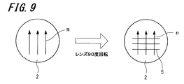
擦過処理としては、図9に示すように、先ずプラスチックレンズ基板2に対し矢印mで示すように一方向に10往復擦過した。その後、プラスチックレンズ基板2を90度回転させて、矢印nで示すように、上述の擦過による擦過痕5に対しほぼ垂直な方向に更に10往復擦過した。ダイヤ研磨布紙の場合は擦過時の荷重を300Gから400Gの範囲とし、メラミンフォームの場合は擦過時の荷重を750G~800Gの範囲とした。
その後、ステップS3として、アセトンを保持した布で基板表面を拭き取った後、超音波28kHz印加のもと、イオン交換水を用いて300秒間の表面浄化処理を行った。超音波洗浄後に、70℃雰囲気下で乾燥させた。
その後、ステップS3として、アセトンを保持した布で基板表面を拭き取った後、超音波28kHz印加のもと、イオン交換水を用いて300秒間の表面浄化処理を行った。超音波洗浄後に、70℃雰囲気下で乾燥させた。
最後に、ハードコート層形成工程(ステップS4)になるが、ここでは、次の3つの段階の処理を行った。まず、第1段階として、プラスチックレンズ基板を、ディッピング法にてハードコート用組成液に30秒間浸漬した。そして、第2段階として、ハードコート用組成液に浸かったプラスチック基板を、速度30cm/分で引き上げた。第3段階として、引き上げたプラスチックレンズ基板を、110℃の温度で60分間、加熱することにより、ハードコート液を硬化してハードコート層を形成した。このように形成したハードコート層の屈折率(ne)は1.65であった。
ここで、ハードコート用組成液の製法について、説明しておく。まず、5℃雰囲気下で、溶媒として、ダイアセトンアルコール(DAA)30質量部と、γ-アミノプロピルトリエトキシシラン2.7質量部を混合した。そして、この混合液にγ-イソシアナトプロピルトリエトキシシラン3.0質量部を攪拌しながら滴下し、4時間攪拌させた。その後、γ-グリシドキシプロピルトリメトキシシラン69.8質量部を混合した後、0.01mol/リットル濃度の塩酸を攪拌しながら滴下し、1昼夜攪拌した。これにより、まず、ハードコートの一つの成分であるシランカップリング剤加水分解品が得られた。
続いて、5℃雰囲気下、別途作製した変性酸化ジルコニウム-酸化第二スズ複合メタノールゾル(日産化学工業(株)製)180質量部を攪拌しながら、ダイアセトンアルコール(DAA)20質量部及びプロピレングリコールモノメチルエーテル(PGM)80質量部を混合した。そして、この混合物を攪拌しながら、変性酸化チタン-酸化スズ-酸化ケイ素-酸化ジルコニウム複合メタノールゾル(触媒化成工業(株)製、商品名:オプトレイク1120Z)62.5質量部をさらに混合し、一時間攪拌した。その後、攪拌しながら先に作製したシランカップリング剤を滴下し、一昼夜攪拌した。
ついで、シリコン系界面活性剤(東レ・ダウコーニング(株)製、商品名:Y-7006)0.25質量部及びアルミニウムトリスアセチルアセトネート5質量部を順次添加し、150時間攪拌した。得られた溶液を0.5μmのフィルターでろ過したものをコーティング組成物とした。
ついで、シリコン系界面活性剤(東レ・ダウコーニング(株)製、商品名:Y-7006)0.25質量部及びアルミニウムトリスアセチルアセトネート5質量部を順次添加し、150時間攪拌した。得られた溶液を0.5μmのフィルターでろ過したものをコーティング組成物とした。
以上説明したように、ハードコート組成物としては、酸化錫、酸化ジルコニウム、酸化ケイ素、酸化チタン等の無機化合物微粒子割合が凡そ20%、シランカップリング剤(γ-グリシドキシプロピルトリメトキシシラン)が凡そ20%、メタノール、1-メトキシ2-プロパノール、4-ヒドロキシ-4-メチル-2-ペンタノン等のアルコール系溶媒が凡そ55%の液が用いられる。残りの略5%は、レベリング剤他の添加剤である。
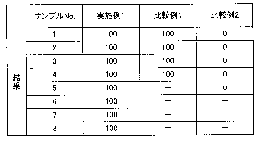
上述の方法で4枚ずつ2組(2種の払拭材用)、合計8枚のレンズを作製し、そのプラスチックレンズ基板とハードコート層との密着性を試験によって確認した。この密着性試験の詳細については後述する。そして、8枚のレンズサンプルで密着性を確認した結果を、実施例1のサンプルNo.1~8として、下記の表1に示す。
[比較例1]
比較例1は、擦過工程(ステップS2)において、研磨剤((株)フジミインコーポレーテッド製、商品名:POLIPLA 103H)を保持したスポンジを用いた。擦過処理の条件(擦過方向及び擦過回数、擦過時の荷重)は上述の実施例1のサンプルNo.1~4と同様とした。また、その他の表面浄化処理工程(ステップS3)、ハードコート層形成工程(ステップS4)も実施例1と同様とした。この方法で4枚のレンズを作製し、実施例1と同様の条件でハードコート層とプラスチックレンズ基板との密着性を試験によって確認した。この結果を、比較例1のサンプルNo.1~4として上記表1に示す。
比較例1は、擦過工程(ステップS2)において、研磨剤((株)フジミインコーポレーテッド製、商品名:POLIPLA 103H)を保持したスポンジを用いた。擦過処理の条件(擦過方向及び擦過回数、擦過時の荷重)は上述の実施例1のサンプルNo.1~4と同様とした。また、その他の表面浄化処理工程(ステップS3)、ハードコート層形成工程(ステップS4)も実施例1と同様とした。この方法で4枚のレンズを作製し、実施例1と同様の条件でハードコート層とプラスチックレンズ基板との密着性を試験によって確認した。この結果を、比較例1のサンプルNo.1~4として上記表1に示す。
[比較例2]
比較例2は、擦過工程(ステップS2)を省略した他は、実施例1と同様の条件で表面浄化処理(ステップS3)、ハードコート層形成工程(ステップS4)を行った。この方法で5枚のレンズを作製し、同様に密着性を試験により確認した。この結果を、比較例2のサンプルNo.1~5として上記表1に示す。
比較例2は、擦過工程(ステップS2)を省略した他は、実施例1と同様の条件で表面浄化処理(ステップS3)、ハードコート層形成工程(ステップS4)を行った。この方法で5枚のレンズを作製し、同様に密着性を試験により確認した。この結果を、比較例2のサンプルNo.1~5として上記表1に示す。
[ハードコートの密着性評価]
上述のプラスチックレンズ基板とハードコート層との密着性を評価した方法は以下の通りである。
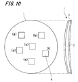
図10は、以上説明した製造方法によって作製したプラスチックレンズ1の正面図と側面図である。図10に示すように、プラスチックレンズ1は、プラスチックレンズ基板2の表面全体にハードコート層3が形成されて構成される。このハードコート層3は、単なる硬化膜でもよいが、反射防止膜を兼ねるようにすることもできる。図5では、分かりやすくするためにハードコート層3を厚く示しているが、実際は2~5μm程度の膜である。
上述のプラスチックレンズ基板とハードコート層との密着性を評価した方法は以下の通りである。
図10は、以上説明した製造方法によって作製したプラスチックレンズ1の正面図と側面図である。図10に示すように、プラスチックレンズ1は、プラスチックレンズ基板2の表面全体にハードコート層3が形成されて構成される。このハードコート層3は、単なる硬化膜でもよいが、反射防止膜を兼ねるようにすることもできる。図5では、分かりやすくするためにハードコート層3を厚く示しているが、実際は2~5μm程度の膜である。
そして密着性の評価にあたって、図10(a)~(f)に示すように、プラスチックレンズ1の表面に形成されたハードコート層3(硬化膜又は反射防止膜)に対して、1つのレンズサンプルにつき、1.5mm間隔で5~6箇所、100目クロスカット4を剃刀によって形成した。そして、このクロスカット4を形成したところに粘着テープ(ニチバン(株)製、セロテープ(登録商標))を強く貼り付けた後、これを急速に剥がし、その後のハードコート膜3の剥離の有無を調べた。100目のうち剥離の生じていない領域の数で評価し、すなわち100のとき剥離なしとなる。また、1目の中で部分的に剥離が生じたものは、その度合いを少数点以下の面積比で評価した。例えば100目のうち、1目において、その10分の1程度の領域に膜剥がれが生じている場合は、99.9として表中に示すこととする。
表1の結果から、実施例1によるプラスチックレンズでは、遊離砥粒を含む研磨剤を使用した比較例1と同様に、密着性に優れることがわかった。一方、擦過処理を施さない比較例2の場合は、密着性が全く得られないことがわかった。
なお、JIS「R6010」の規格によると、電気抵抗試験方法により測定される研磨材用微粉(砥粒)の粒度として、#1500の研磨布紙の場合は、累積沈降高さ50%の粒子径が、「9.7±0.8μm」と規定されている。なお、電気抵抗試験方法については、JIS「R6012」において規定されている。
つまり、電気抵抗試験方法による累積沈降高さ50%の粒子径がおよそ10μmの砥粒を有する研磨シートを用いて擦過を行う場合に、良好な密着性が得られることがわかる。
つまり、電気抵抗試験方法による累積沈降高さ50%の粒子径がおよそ10μmの砥粒を有する研磨シートを用いて擦過を行う場合に、良好な密着性が得られることがわかる。
<評価2>
次に、擦過処理に用いる払拭材として研磨シートを用いる場合に、その粒度の番号を大きくする(砥粒の粒子径をより小さくする)と共に、擦過処理後の表面浄化工程を行わない場合について、密着性の評価を行った。なお、本評価において、擦過処理は乾式環境下で行った。
[実施例2]
擦過処理後の表面浄化処理工程を省略したほかは、上述の実施例1と同様の製造工程を経て3枚のプラスチックレンズを作製した。先ず、ステップS1として用意するプラスチックレンズ基板としては、実施例1と同様に、チオウレタン系レンズ基板(屈折率ne:1.67、HOYA(株)製、商品名:アイノア)を用いた。
次に、擦過処理に用いる払拭材として研磨シートを用いる場合に、その粒度の番号を大きくする(砥粒の粒子径をより小さくする)と共に、擦過処理後の表面浄化工程を行わない場合について、密着性の評価を行った。なお、本評価において、擦過処理は乾式環境下で行った。
[実施例2]
擦過処理後の表面浄化処理工程を省略したほかは、上述の実施例1と同様の製造工程を経て3枚のプラスチックレンズを作製した。先ず、ステップS1として用意するプラスチックレンズ基板としては、実施例1と同様に、チオウレタン系レンズ基板(屈折率ne:1.67、HOYA(株)製、商品名:アイノア)を用いた。
次に、ステップS2において、研磨シートとして、(株)ノリタケコーテッドアブレーシブ社製、商品名:ダイヤ研磨布紙、#10000を用いて擦過処理を行った。
この例では、擦過処理は乾式環境下で行った。その他の擦過処理の条件(擦過方向及び擦過回数、擦過時の荷重)は上述の実施例1のサンプルNo.1~4と同様である。この場合の密着性の評価結果を下記の表2に示す。各レンズサンプル2-1,2-2,2-3において6箇所の100目クロスカットを行い、その平均をレンズ平均とし、実施例2全体の平均を「平均」として示す。
この例では、擦過処理は乾式環境下で行った。その他の擦過処理の条件(擦過方向及び擦過回数、擦過時の荷重)は上述の実施例1のサンプルNo.1~4と同様である。この場合の密着性の評価結果を下記の表2に示す。各レンズサンプル2-1,2-2,2-3において6箇所の100目クロスカットを行い、その平均をレンズ平均とし、実施例2全体の平均を「平均」として示す。
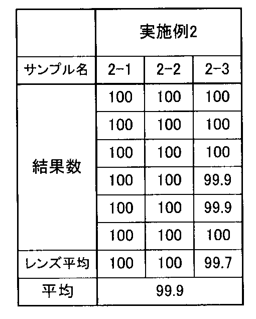
上記表2の結果から、実施例2により製造したプラスチックレンズでは、擦過工程を乾式環境下で行っているものであるが、擦過工程を湿式環境下で行う実施例1による場合と同様の優れた密着性が得られることがわかった。また、擦過処理後の表面浄化工程を行わない場合でも、良好な密着性が得られることを確認できた。
なお、JIS「R6010」においては、#10000の研磨シートの粒子径は規定されていないが、研磨シートの各メーカーにおける#10000の研磨シートの研磨材の粒度は、電気抵抗試験方法による累積沈降高さ50%の粒子径がおよそ0.5μm~1.0μm程度である。つまり、電気抵抗試験方法による累積沈降高さ50%の粒子径が0.5μm~1.0μmの粒子径の砥粒を有する研磨シートを用いる場合に、良好な密着性が得られることがわかる。
また、実施例1及び2の結果から、電気抵抗試験方法による累積沈降高さ50%の粒子径が10μm以下の粒子径の砥粒を有する研磨シートを用いて擦過することで、良好な密着性をもったプラスチックレンズを製造することができるといえる。
また、実施例1及び2の結果から、電気抵抗試験方法による累積沈降高さ50%の粒子径が10μm以下の粒子径の砥粒を有する研磨シートを用いて擦過することで、良好な密着性をもったプラスチックレンズを製造することができるといえる。
<評価3>
次に、本発明の実施例として払拭材を用いて擦過処理を行う実施例と、通常の眼鏡拭きで擦過処理を行う比較例とについてアルカリ洗浄を伴う製造方法によりプラスチックレンズを作製し、密着性を比較した。
[実施例3]
前述の図6のフローチャートに示す製造工程に沿って、2種類の払拭材で擦過処理を施したプラスチック基板を用いてそれぞれ3枚ずつのプラスチックレンズを作製した。
先ず、ステップS11で用意されるプラスチックレンズ基板として、実施例1と同様にチオウレタン系レンズ基板(屈折率ne:1.67、HOYA(株)製、商品名:アイノア)を用意した。
次に、ステップS23として、プラスチックレンズ基板をアルカリ溶液に漬浸し、レンズ表面の化学エッジング処理を行った。この条件は、下記の通りである。
アルカリ溶液:10%水酸化ナトリウム水溶液
アルカリ溶液温度:60℃
漬浸時間:100秒
漬浸条件:超音波28kHz印加
次に、本発明の実施例として払拭材を用いて擦過処理を行う実施例と、通常の眼鏡拭きで擦過処理を行う比較例とについてアルカリ洗浄を伴う製造方法によりプラスチックレンズを作製し、密着性を比較した。
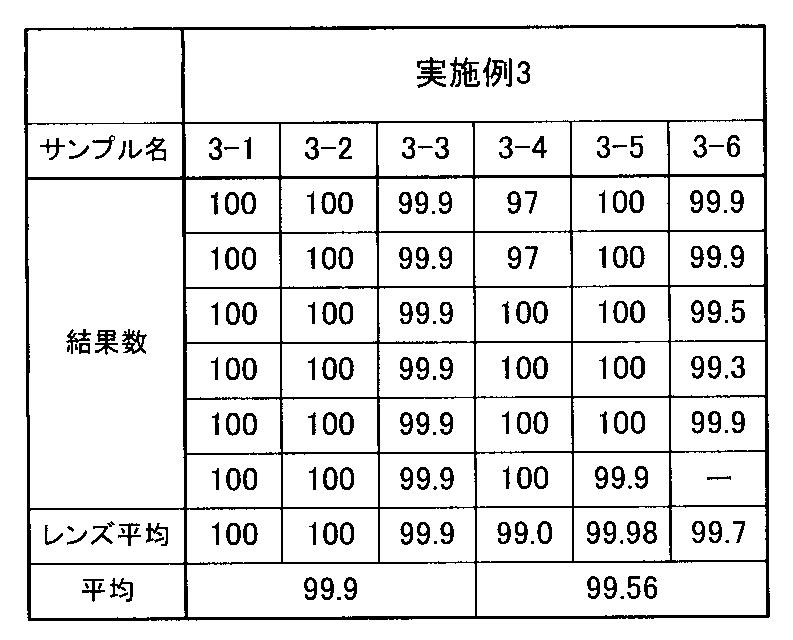
[実施例3]
前述の図6のフローチャートに示す製造工程に沿って、2種類の払拭材で擦過処理を施したプラスチック基板を用いてそれぞれ3枚ずつのプラスチックレンズを作製した。
先ず、ステップS11で用意されるプラスチックレンズ基板として、実施例1と同様にチオウレタン系レンズ基板(屈折率ne:1.67、HOYA(株)製、商品名:アイノア)を用意した。
次に、ステップS23として、プラスチックレンズ基板をアルカリ溶液に漬浸し、レンズ表面の化学エッジング処理を行った。この条件は、下記の通りである。
アルカリ溶液:10%水酸化ナトリウム水溶液
アルカリ溶液温度:60℃
漬浸時間:100秒
漬浸条件:超音波28kHz印加
次に、ステップS13の擦過工程で使用した払拭材は、プラスチックレンズ基板の表面を布ヤスリ(実施例3-1,3-2、3-3)とメラミンフォーム(実施例3-4,3-5,3-6)である。これらの払拭材で擦過し、物理エッジング処理を行った。この例では、布ヤスリとして、(株)ノリタケコーテッドアブレーシブ製、商品名:ダイヤ研磨布紙、#1500を用い、メラミンフォームはレック(株)製のものを用いた。また、擦過工程の条件(擦過方向、擦過回数、擦過時の荷重)は実施例1のサンプルNo.1~4、5~8とそれぞれ同様とした。
そして、ステップS14として、プラスチックレンズ基板にハードコート層を形成した。なお、このハードコート層の形成工程は、上述の実施例1と同様とした。ハードコート組成液の組成及び調整方法も、実施例1と同様とした。サンプル名は、払拭材として布ヤスリを使用した場合を実施例3-1、実施例3-2、実施例3-3、メラミンフォームを使用した場合を実施例3-4、実施例3-5、実施例3-6として下記の表3に示す。表3においては、結果数として、上述の図10に示す評価方法と同様の評価を行い、膜剥がれの生じない個数を示す。この場合も実施例2と同様に各レンズサンプルにおいて5乃至6箇所の100目クロスカットを行い、その平均をレンズ平均とし、実施例3全体の平均を「平均」として示す。
[実施例4]
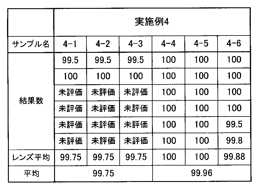
実施例3の製造方法のアルカリ洗浄工程(ステップS12)において、漬浸時間を180秒に変えた他は、同様の条件、同様の製造工程で3枚のプラスチックレンズを作製した。払拭材として布ヤスリを用いたサンプル名を実施例4-1、実施例4-2、実施例4-3とし、メラミンフォームを用いたサンプル名を実施例4-4、実施例4-5、実施例4-6として、密着性の評価結果を下記表4に示す。サンプル4-1,4-2,4-3では2箇所、4-4,4-5,4-6では6箇所の100目クロスカットを行い、実施例2及び3と同様にレンズ平均と平均を算出した。
実施例3の製造方法のアルカリ洗浄工程(ステップS12)において、漬浸時間を180秒に変えた他は、同様の条件、同様の製造工程で3枚のプラスチックレンズを作製した。払拭材として布ヤスリを用いたサンプル名を実施例4-1、実施例4-2、実施例4-3とし、メラミンフォームを用いたサンプル名を実施例4-4、実施例4-5、実施例4-6として、密着性の評価結果を下記表4に示す。サンプル4-1,4-2,4-3では2箇所、4-4,4-5,4-6では6箇所の100目クロスカットを行い、実施例2及び3と同様にレンズ平均と平均を算出した。
[比較例3]
実施例1の擦過工程で、払拭材として一般的な眼鏡拭き(ポリエステル製)でプラスチックレンズ基板を擦過したことをのぞくと、実施例1と同様の方法で3枚のレンズを作製した。比較例に用いた一般的な眼鏡拭きはプラスチックレンズ基板よりも明らかに軟質な材料で構成されているものである。サンプル名を比較例C3-1、比較例C3-2、比較例C3-3として、下記表5に示す。
実施例1の擦過工程で、払拭材として一般的な眼鏡拭き(ポリエステル製)でプラスチックレンズ基板を擦過したことをのぞくと、実施例1と同様の方法で3枚のレンズを作製した。比較例に用いた一般的な眼鏡拭きはプラスチックレンズ基板よりも明らかに軟質な材料で構成されているものである。サンプル名を比較例C3-1、比較例C3-2、比較例C3-3として、下記表5に示す。
[比較例4]
実施例3の擦過工程で、払拭材として一般的な眼鏡拭き(ポリエステル製)でレンズ基板を擦過したことをのぞくと、実施例2と同様の方法で3枚のレンズを作製した。サンプル名を比較例C4-1、比較例C4-2、比較例C4-3として、密着性の評価結果を実施例2及び3、比較例3と同様に、下記表5に示す。
実施例3の擦過工程で、払拭材として一般的な眼鏡拭き(ポリエステル製)でレンズ基板を擦過したことをのぞくと、実施例2と同様の方法で3枚のレンズを作製した。サンプル名を比較例C4-1、比較例C4-2、比較例C4-3として、密着性の評価結果を実施例2及び3、比較例3と同様に、下記表5に示す。
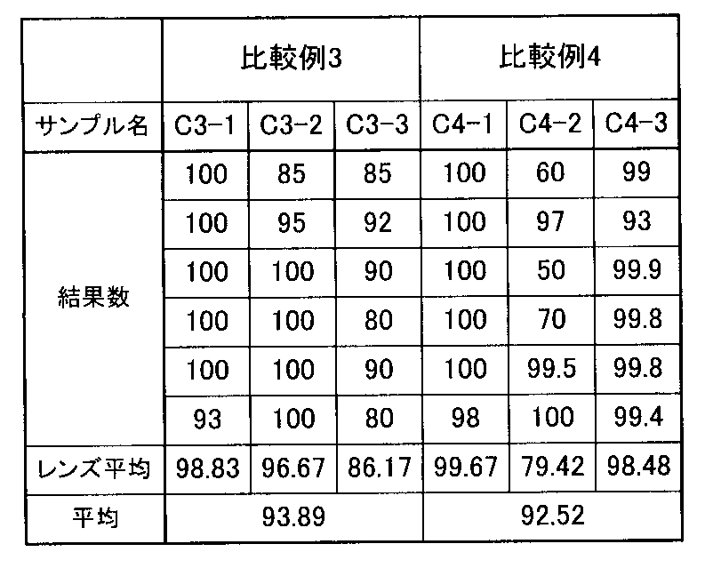
上記表2~5の結果より、実施例2~4におけるように、布ヤスリやメラミンフォーム等の払拭材で擦過処理を施したプラスチックレンズは、評価の「平均」がいずれも略100に保たれており、優れた密着性であることがわかった。一方、比較例3及び4においては、擦過加工をポリエステル製の眼鏡拭きで行っており、軟らかいポリエステル製眼鏡拭きでは、評価の「平均」が95以下となってしまい、密着性が不十分であることがわかった。これは、ポリエステル眼鏡拭きの擦過では製造過程の析出により強力に付着した夾雑物は充分に除去できず、また、レンズ表面を粗面化する表面改質を行えないためと考えられる。
<評価4>
次に、擦過処理に用いる払拭材として研磨シートを用いる場合の粒度の番号を大きくすると共に、アルカリ洗浄等の化学エッジング工程を行わず、また擦過処理後の表面浄化工程を行わない場合について、密着性の評価を行った。
[実施例5]
擦過処理前のアルカリ洗浄等の化学エッジング工程を省略した他は、上述の実施例3と同様の製造工程を経てプラスチックレンズを作製した。プラスチックレンズ基板としては、実施例1~4と同様に、チオウレタン系レンズ基板(屈折率ne:1.67、HOYA(株)製、商品名:アイノア)を用いた。
次に、擦過処理に用いる払拭材として研磨シートを用いる場合の粒度の番号を大きくすると共に、アルカリ洗浄等の化学エッジング工程を行わず、また擦過処理後の表面浄化工程を行わない場合について、密着性の評価を行った。
[実施例5]
擦過処理前のアルカリ洗浄等の化学エッジング工程を省略した他は、上述の実施例3と同様の製造工程を経てプラスチックレンズを作製した。プラスチックレンズ基板としては、実施例1~4と同様に、チオウレタン系レンズ基板(屈折率ne:1.67、HOYA(株)製、商品名:アイノア)を用いた。
なお、この例においては、擦過処理を行う払拭材としてダイヤモンド布ヤスリを用いた。布ヤスリとしては、(株)ノリタケコーテッドアブレーシブ社製、商品名:ダイヤ研磨布紙、#6000を用いた。
擦過処理の条件は、前述の実施例1のサンプルNo.1~4において説明した擦過処理と同様の条件(擦過方向、擦過回数及び擦過時の荷重)とした。この場合の密着性の評価結果を下記表6に示す。
擦過処理の条件は、前述の実施例1のサンプルNo.1~4において説明した擦過処理と同様の条件(擦過方向、擦過回数及び擦過時の荷重)とした。この場合の密着性の評価結果を下記表6に示す。
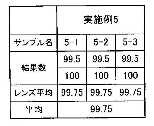
この表6から明らかなように、実施例5においても、プラスチックレンズ基板とハードコート層との密着性が充分得られることがわかった。つまり、アルカリ洗浄を伴わずに研磨処理を行っても、密着性が充分得られるといえる。
したがって、プライマー層を形成する仕様のプラスチックレンズに適用する場合は、プライマー層材料として耐アルカリ性を考慮する必要がなく、選択自由度が高まることとなる。したがって、プライマー層を設ける眼鏡等のプラスチックレンズの製造方法に適用する場合は、比較的コストの低い材料や、製造・取り扱いの容易な材料を選択することも可能となるという利点がある。
したがって、プライマー層を形成する仕様のプラスチックレンズに適用する場合は、プライマー層材料として耐アルカリ性を考慮する必要がなく、選択自由度が高まることとなる。したがって、プライマー層を設ける眼鏡等のプラスチックレンズの製造方法に適用する場合は、比較的コストの低い材料や、製造・取り扱いの容易な材料を選択することも可能となるという利点がある。
以上説明したように、本発明によれば、遊離砥粒を含む研磨剤による表面改質を行わずに、プラスチックレンズ基板とハードコート層との密着性を確保することができる。砥粒が表面に殆ど残留しないため、擦過処理後の残渣の浄化工程に要する時間を短縮し、すなわち浄化工程を簡易化できるか、もしくは表面浄化工程を省略することが可能となる。
また、擦過工程を湿潤環境で行うことにより、僅かに生じる擦過残渣が基板表面に付着しにくくなり、擦過直後のレンズ基板表面をより確実に清浄に保つことができる。その結果、擦過処理後の洗浄処理がより容易になり、擦過残渣による膜浮きを抑制することができる。また、湿潤環境で実施することにより、擦過残渣の微粒が起点となる膜はがれも効果的に抑制できることから、長期にわたって密着性が得られる。
更に、従来行われていたような表面改質処理としてのプラズマ処理やアルカリ処理によるレンズ表面の化学変化を要しないため、前処理を簡略化することができる。
プライマー層は、ハードコートと基板の密着性を向上させる効果のほかに耐衝撃性を向上させる効果を有している。しかし、耐衝撃性が得られるプライマー層は、ポリウレタン系の樹脂層で構成されており、ハードコート層との密着性を高めるために、アルカリ洗浄や紫外線照射、オゾンによる酸化処理等を行うとプライマー層が劣化することが懸念される。
しかしながら、本発明による場合は布ヤスリ等の研磨シートを用いて擦過処理を行うのみであるので、アルカリ洗浄や紫外線照射、オゾンよる表面酸化処理を要さない。その結果、プライマー層を犠牲にすることなくハードコート層を形成することができるので、レンズ基板の劣化現象を抑制することができ、表面加工性に優れたプラスチックレンズの製造方法を提供することが可能となる。
プライマー層は、ハードコートと基板の密着性を向上させる効果のほかに耐衝撃性を向上させる効果を有している。しかし、耐衝撃性が得られるプライマー層は、ポリウレタン系の樹脂層で構成されており、ハードコート層との密着性を高めるために、アルカリ洗浄や紫外線照射、オゾンによる酸化処理等を行うとプライマー層が劣化することが懸念される。
しかしながら、本発明による場合は布ヤスリ等の研磨シートを用いて擦過処理を行うのみであるので、アルカリ洗浄や紫外線照射、オゾンよる表面酸化処理を要さない。その結果、プライマー層を犠牲にすることなくハードコート層を形成することができるので、レンズ基板の劣化現象を抑制することができ、表面加工性に優れたプラスチックレンズの製造方法を提供することが可能となる。
なお、本発明は上述の実施形態例において説明した構成に限定されるものではなく、その他本発明構成を逸脱しない範囲において種々の変形、変更が可能である。
1.プラスチックレンズ、2.プラスチックレンズ基板、3.ハードコート層、4.クロスカット、5.擦過痕
Claims (12)
- プラスチックレンズ基板の表面を払拭材を用いて擦過する擦過工程と、
前記擦過したプラスチックレンズ基板の表面に、湿式表面処理によりハードコート層を形成する工程と、
を含み、
前記払拭材は、可撓性を有しており、前記プラスチックレンズ基板表面の素材よりも硬質な材料で構成されるか、又は、前記プラスチックレンズ基板表面の素材よりも硬質な材料が可撓性を有する基材上に固定されて構成される
プラスチックレンズの製造方法。 - 前記擦過工程において、前記プラスチックレンズ基板の表面に擦過痕を形成する請求項1に記載のプラスチックレンズの製造方法。
- 前記プラスチックレンズ基板を化学エッジングする工程を前記擦過工程の前又は後に含む請求項1又は2のいずれかに記載のプラスチックレンズの製造方法。
- 前記化学エッジングする工程は、アルカリ性水溶液を用いて行う請求項3に記載のプラスチックレンズの製造方法。
- 前記擦過工程を湿潤環境で行う請求項1~4のいずれかに記載のプラスチックレンズの製造方法。
- 更に、前記プラスチックレンズ基板の一方の面に、プライマー層を形成する工程を含む請求項1~5のいずれか1項に記載のプラスチックレンズの製造方法。
- 前記払拭材が、砥粒が固定されて成る研磨シートである請求項1~6のいずれかに記載のプラスチックレンズの製造方法。
- 前記砥粒は、電気抵抗試験方法による累積沈降高さ50%の粒子径がおよそ10μm以下であり0.1μm以上である請求項7に記載のプラスチックレンズの製造方法。
- 前記研磨シートは、砥粒が織布又は不織布に固定されている請求項7又は8に記載のプラスチックレンズの製造方法。
- 前記砥粒がダイヤモンドであることを特徴とする請求項7~9のいずれかに記載のプラスチックレンズの製造方法。
- 前記払拭材が、メラミン樹脂発泡体である請求項1~6のいずれかに記載のプラスチックレンズの製造方法
- 前記プラスチックレンズ基板は、チオウレタン系プラスチックより成る請求項1~11のいずれかに記載のプラスチックレンズの製造方法。
Priority Applications (3)
| Application Number | Priority Date | Filing Date | Title |
|---|---|---|---|
| EP09722698.9A EP2267513A4 (en) | 2008-03-17 | 2009-02-24 | METHOD FOR PRODUCING A PLASTIC LENS |
| US12/933,004 US20110011832A1 (en) | 2008-03-17 | 2009-02-24 | Method for producing plastic lens |
| JP2010503812A JP5202622B2 (ja) | 2008-03-17 | 2009-02-24 | プラスチックレンズの製造方法 |
Applications Claiming Priority (4)
| Application Number | Priority Date | Filing Date | Title |
|---|---|---|---|
| JP2008068400 | 2008-03-17 | ||
| JP2008-068400 | 2008-03-17 | ||
| JP2008270154 | 2008-10-20 | ||
| JP2008-270154 | 2008-10-20 |
Publications (1)
| Publication Number | Publication Date |
|---|---|
| WO2009116362A1 true WO2009116362A1 (ja) | 2009-09-24 |
Family
ID=41090770
Family Applications (1)
| Application Number | Title | Priority Date | Filing Date |
|---|---|---|---|
| PCT/JP2009/053257 Ceased WO2009116362A1 (ja) | 2008-03-17 | 2009-02-24 | プラスチックレンズの製造方法 |
Country Status (4)
| Country | Link |
|---|---|
| US (1) | US20110011832A1 (ja) |
| EP (1) | EP2267513A4 (ja) |
| JP (1) | JP5202622B2 (ja) |
| WO (1) | WO2009116362A1 (ja) |
Cited By (2)
| Publication number | Priority date | Publication date | Assignee | Title |
|---|---|---|---|---|
| JP2012210558A (ja) * | 2011-03-30 | 2012-11-01 | Asahi Kasei E-Materials Corp | 親水性塗膜の形成方法、及び親水性塗膜 |
| JP2018205755A (ja) * | 2012-11-01 | 2018-12-27 | エシロール・アンテルナシオナル | 熱的に影響される可変着色デバイス |
Families Citing this family (1)
| Publication number | Priority date | Publication date | Assignee | Title |
|---|---|---|---|---|
| US10421668B2 (en) * | 2016-03-28 | 2019-09-24 | Shenzhen University | Method for preparing tungsten sulfide thin film |
Citations (3)
| Publication number | Priority date | Publication date | Assignee | Title |
|---|---|---|---|---|
| JPH0570615A (ja) | 1991-09-13 | 1993-03-23 | Seiko Epson Corp | 表面清浄化・改質方法 |
| JPH11316302A (ja) | 1998-05-06 | 1999-11-16 | Asahi Optical:Kk | プラスチックレンズの製造方法 |
| JP2001288406A (ja) | 2000-04-04 | 2001-10-16 | Seiko Epson Corp | プライマー組成物およびプライマー付きハードコートレンズおよびハードマルチコートレンズ |
Family Cites Families (8)
| Publication number | Priority date | Publication date | Assignee | Title |
|---|---|---|---|---|
| JPS6044646B2 (ja) * | 1974-04-10 | 1985-10-04 | 東京光学機械株式会社 | 強化レンズの製造方法 |
| US5632668A (en) * | 1993-10-29 | 1997-05-27 | Minnesota Mining And Manufacturing Company | Method for the polishing and finishing of optical lenses |
| JP3999305B2 (ja) * | 1997-04-21 | 2007-10-31 | 株式会社アサヒオプティカル | 光学用熱可塑性ウレタン樹脂レンズの製造方法とそのレンズ |
| JPH1148117A (ja) * | 1997-08-01 | 1999-02-23 | Seiko Epson Corp | 光学材料の表面改質方法 |
| US6503615B1 (en) * | 1998-08-28 | 2003-01-07 | Inoac Corporation | Wiping cleaner |
| US6220703B1 (en) * | 1999-12-29 | 2001-04-24 | Younger Manufacturing Co., Inc. | Ophthalmic lenses utilizing polyethylene terephthalate polarizing films |
| US20040137244A1 (en) * | 2002-12-30 | 2004-07-15 | Eitan Zeira | Surface treatment for increasing transmission of a transparent article |
| US20060003912A1 (en) * | 2004-07-02 | 2006-01-05 | Lindsay Jeffrey D | Kits of foam based cleaning elements |
-
2009
- 2009-02-24 US US12/933,004 patent/US20110011832A1/en not_active Abandoned
- 2009-02-24 JP JP2010503812A patent/JP5202622B2/ja not_active Expired - Fee Related
- 2009-02-24 WO PCT/JP2009/053257 patent/WO2009116362A1/ja not_active Ceased
- 2009-02-24 EP EP09722698.9A patent/EP2267513A4/en not_active Withdrawn
Patent Citations (3)
| Publication number | Priority date | Publication date | Assignee | Title |
|---|---|---|---|---|
| JPH0570615A (ja) | 1991-09-13 | 1993-03-23 | Seiko Epson Corp | 表面清浄化・改質方法 |
| JPH11316302A (ja) | 1998-05-06 | 1999-11-16 | Asahi Optical:Kk | プラスチックレンズの製造方法 |
| JP2001288406A (ja) | 2000-04-04 | 2001-10-16 | Seiko Epson Corp | プライマー組成物およびプライマー付きハードコートレンズおよびハードマルチコートレンズ |
Non-Patent Citations (1)
| Title |
|---|
| See also references of EP2267513A4 |
Cited By (2)
| Publication number | Priority date | Publication date | Assignee | Title |
|---|---|---|---|---|
| JP2012210558A (ja) * | 2011-03-30 | 2012-11-01 | Asahi Kasei E-Materials Corp | 親水性塗膜の形成方法、及び親水性塗膜 |
| JP2018205755A (ja) * | 2012-11-01 | 2018-12-27 | エシロール・アンテルナシオナル | 熱的に影響される可変着色デバイス |
Also Published As
| Publication number | Publication date |
|---|---|
| US20110011832A1 (en) | 2011-01-20 |
| EP2267513A1 (en) | 2010-12-29 |
| JPWO2009116362A1 (ja) | 2011-07-21 |
| EP2267513A4 (en) | 2014-05-14 |
| JP5202622B2 (ja) | 2013-06-05 |
Similar Documents
| Publication | Publication Date | Title |
|---|---|---|
| EP1669795B1 (en) | Stainproof eyeglass lens and method for production thereof | |
| US4301193A (en) | Process for restoration of clear plastic | |
| JP6881301B2 (ja) | ガラス板の製造方法 | |
| JP4469496B2 (ja) | 撥水性表面処理 | |
| JP6257897B2 (ja) | 光学物品およびその製造方法 | |
| US20100200541A1 (en) | Method for Preparing the Surface of a Lens Including an Anti-Soiling Coating for Edging the Same | |
| US8128718B2 (en) | Compositions and methods for removing scratches from plastic surfaces | |
| KR100538196B1 (ko) | 클리닝 시트 | |
| JP5202622B2 (ja) | プラスチックレンズの製造方法 | |
| JP5524060B2 (ja) | 二層仮皮膜を有する光学物品 | |
| CN106470800B (zh) | 研磨膜 | |
| JP4115722B2 (ja) | 情報記録媒体用ガラス基板の製造方法 | |
| JP5977606B2 (ja) | ワークの表面を処理するための研磨粒子付き表面処理用シート | |
| JP2004157147A (ja) | 防汚性眼鏡レンズの製造方法 | |
| JP2004330327A (ja) | レンズの切削・研磨加工に用いるレンズ固定用部材及びそれを用いるレンズの切削・研磨加工方法 | |
| JP2017521706A (ja) | 2つの表面のそれぞれで異なる防汚性を有する眼用レンズ及び製造方法 | |
| JP2004061866A (ja) | 防汚性眼鏡レンズの製造方法 | |
| JP4577296B2 (ja) | 磁気記録媒体用非金属基板の再生方法 | |
| JPH10216657A (ja) | 有機光学要素の積層塗膜除去方法 | |
| JP2018051727A (ja) | 研磨パッド及びその製造方法 | |
| JP3597152B2 (ja) | レンズの製造方法 | |
| JP2002036128A (ja) | 研磨シート | |
| JP2010113090A (ja) | プラスチックレンズとその製造方法 | |
| JP5534834B2 (ja) | 保持パッド及び研磨加工方法 | |
| JP3064251B2 (ja) | 除塵シートおよびその製造方法 |
Legal Events
| Date | Code | Title | Description |
|---|---|---|---|
| 121 | Ep: the epo has been informed by wipo that ep was designated in this application |
Ref document number: 09722698 Country of ref document: EP Kind code of ref document: A1 |
|
| WWE | Wipo information: entry into national phase |
Ref document number: 2010503812 Country of ref document: JP |
|
| WWE | Wipo information: entry into national phase |
Ref document number: 2009722698 Country of ref document: EP |
|
| WWE | Wipo information: entry into national phase |
Ref document number: 12933004 Country of ref document: US |
|
| NENP | Non-entry into the national phase |
Ref country code: DE |