WO2009117909A1 - 物理随机接入信道的映射方法 - Google Patents
物理随机接入信道的映射方法 Download PDFInfo
- Publication number
- WO2009117909A1 WO2009117909A1 PCT/CN2009/070413 CN2009070413W WO2009117909A1 WO 2009117909 A1 WO2009117909 A1 WO 2009117909A1 CN 2009070413 W CN2009070413 W CN 2009070413W WO 2009117909 A1 WO2009117909 A1 WO 2009117909A1
- Authority
- WO
- WIPO (PCT)
- Prior art keywords
- frequency
- prach
- random access
- mapping
- physical random
- Prior art date
- Legal status (The legal status is an assumption and is not a legal conclusion. Google has not performed a legal analysis and makes no representation as to the accuracy of the status listed.)
- Ceased
Links
Classifications
-
- H—ELECTRICITY
- H04—ELECTRIC COMMUNICATION TECHNIQUE
- H04W—WIRELESS COMMUNICATION NETWORKS
- H04W74/00—Wireless channel access
- H04W74/08—Non-scheduled access, e.g. ALOHA
- H04W74/0866—Non-scheduled access, e.g. ALOHA using a dedicated channel for access
-
- H—ELECTRICITY
- H04—ELECTRIC COMMUNICATION TECHNIQUE
- H04L—TRANSMISSION OF DIGITAL INFORMATION, e.g. TELEGRAPHIC COMMUNICATION
- H04L5/00—Arrangements affording multiple use of the transmission path
- H04L5/0001—Arrangements for dividing the transmission path
- H04L5/0003—Two-dimensional division
- H04L5/0005—Time-frequency
- H04L5/0007—Time-frequency the frequencies being orthogonal, e.g. OFDM(A) or DMT
-
- H—ELECTRICITY
- H04—ELECTRIC COMMUNICATION TECHNIQUE
- H04L—TRANSMISSION OF DIGITAL INFORMATION, e.g. TELEGRAPHIC COMMUNICATION
- H04L5/00—Arrangements affording multiple use of the transmission path
- H04L5/003—Arrangements for allocating sub-channels of the transmission path
- H04L5/0053—Allocation of signalling, i.e. of overhead other than pilot signals
-
- H—ELECTRICITY
- H04—ELECTRIC COMMUNICATION TECHNIQUE
- H04L—TRANSMISSION OF DIGITAL INFORMATION, e.g. TELEGRAPHIC COMMUNICATION
- H04L5/00—Arrangements affording multiple use of the transmission path
- H04L5/003—Arrangements for allocating sub-channels of the transmission path
- H04L5/0058—Allocation criteria
- H04L5/0073—Allocation arrangements that take into account other cell interferences
Definitions
- FIG. 1 is a schematic diagram of a frame structure of a Time Division Duplex (TDD) mode of an LTE system. As shown in FIG.
- TDD Time Division Duplex
- the radio frame is divided into two fields, each of which is 5ms long (153600Ts), including 8 normal time slots of length 0.5ms, and three special time slots, that is, downlink pilot time slots (Downlink Pilot Time Slot) , referred to as DwPTS for short, Guard Period (GP) and Uplink Pilot Time Slot (UpPTS for short), and the sum of the lengths of these three special time slots is lms ( 30720Ts ).
- Frame 1 is always composed of three special time slots; when there are 2 downlink to uplink transition points within 10ms, subframe 6 consists of three special time slots.
- subframe 6 only contains DwPTS (in this case DwPTS)
- the length is lms
- the other subframes are composed of 2 normal time slots.
- subframes 0, 5 and DwPTS are used for downlink transmission
- subframe 2 and UpPTS are used for uplink transmission.
- PRACH Physical Random Access CHannel
- the first type is in the general uplink subframe. In the transmission (subframes that do not contain special time slots), there are four types of PRACH in this category, which are:
- Preamble format 0 occupies 1 uplink subframe
- Cyclic Prefix CP
- preamble preamble
- Preamble format 1 2 The uplink subframe
- CP Cyclic Prefix
- preamble (preamble) length is 24576Ts
- Preamble format 2 2 uplink subframes, CP (Cyclic Prefix) is 6240TS, preamble (leading) length is 2 ⁇ 24576Ts;
- Preamble format 3 3 uplink subframes, CP (Cyclic Prefix) length is 21024Ts, preamble (preamble) length is 2 24576Ts; the second type is transmitted in UpPTS, there is one type of PRACH, which is Preamble Format 4, CP length is 448Ts, preamble (preamble) length is 4096Ts; In frequency or frequency, the above various PRACHs occupy 6 resource blocks (Resource Blocks, referred to as RBs), each RB contains 12 subcarriers, each sub- The carrier has a bandwidth of 15 kHz. When the mobile phone accesses the system, it first needs to perform downlink synchronization.
- RBs Resource Blocks
- the mobile phone demodulates the broadcast channel to obtain the PRACH configuration parameters, and finally completes the uplink synchronization through the PRACH to establish a connection with the base station.
- the format and density are the same but the versions are different, meaning that the preamble format is the same, the number of PRACHs per unit time is the same, but the time or frequency or position of these PRACHs is different.
- multiple versions of the PRACH of the same density are set.
- the purpose of using different versions of different cells is to break the PRACH of different cells managed by the same base station in time, so that the cells managed by the same base station are different.
- the PRACH processing request is always raised to avoid the phenomenon that the base station is too busy at some moments and no data processing at other moments.
- the PRACH of the type preamble format 4 since the UpPTS does not transmit data, different cells use different versions, and the PRACH of each cell has different time domain or frequency domain location, and there is also PRACH between the descending cells. 4 especially the role.
- the mobile phone uses the preparation parameters of the PRACH to obtain the time and frequency position of the PRACH available to the cell according to an algorithm.
- the present invention aims to provide a mapping method of a physical random access channel to solve at least one of the above problems.
- w is evenly mapped from high frequency (or low frequency) to low frequency (or high frequency) in the available frequency band, and is odd in the available frequency band from low frequency (or high frequency) ) is mapped to high frequency (or low frequency)
- one physical random access channel occupies 6 consecutive resource blocks in the frequency domain, and the frequency bands occupied by two adjacent physical random access channels in the frequency domain do not overlap.
- For each version number r use phase w ⁇
- the physical random access channel occupies 6 consecutive resource blocks in the frequency domain, and the frequency bands occupied by two adjacent physical random access channels in the frequency domain do not overlap.
- mapping process is used for each version number r; or w is evenly mapped from high frequency (or low frequency) to low frequency (or high frequency) in the available frequency band, and is odd in the available frequency band from low frequency (or high) Frequency) is mapped to high frequency (or low frequency), and one of the physical random access channels occupies 6 consecutive resource blocks in the frequency domain, and two physical spaces adjacent in the frequency domain w ⁇
- the frequency band occupied by the random access channel has no overlap; or the first half ( or
- PRACH is mapped from high frequency (or low frequency) to low frequency (or high frequency) in the available frequency band
- the latter half PRACH is mapped from low frequency (or high frequency) to high frequency (or low frequency) in the available frequency band
- one physical The random access channel occupies 6 consecutive resource blocks in the frequency domain, and the frequency bands occupied by two adjacent physical random access channels in the frequency domain do not overlap.
- the version number r is obtained by the following operation:
- the version number of the physical random access channel configuration type sent by the base station is directly obtained.
- the frequency domain mapping formula for mapping in the frequency domain is:
- ⁇ is the frequency number of the first resource block that can be used for the PRACH in the low frequency, and is the total number of resource blocks corresponding to the uplink bandwidth
- (4, j is the frequency domain mapping index of the preamble format 0 ⁇ 3, that is, belongs to the same cell
- the version number is r
- the time domain location is determined by the parameter (the number of all physical random access channels with the same time domain location in V; used to indicate which radio frame the physical random access channel is in; used to indicate that the physical random access channel is in Which field is used to indicate which subframe of the physical random access channel is within one field.
- the mapping method of the physical random access channel of the above embodiment overcomes the same because the version number factor is considered in the mapping.
- FIG. 1 shows a frame structure of an LTE system TDD mode
- FIG. 2 shows a schematic diagram of available frequency resources
- FIG. 3 shows a result of Embodiment 1 mapping.
- Example 1 shows an example 2 of the mapping result of the first embodiment
- FIG. 5 shows an example 1 of the result of the sixth embodiment mapping
- FIG. 6 shows an example 2 of the result of the sixth embodiment mapping
- FIG. 1 shows a frame structure of an LTE system TDD mode
- FIG. 2 shows a schematic diagram of available frequency resources
- FIG. 3 shows a result of Embodiment 1 mapping.
- Example 1 shows an example 2 of the mapping result of the first embodiment
- FIG. 5 shows an example 1 of the result of the sixth embodiment mapping
- FIG. 6 shows an example 2 of the result of the sixth embodiment mapping
- FIG. 1 shows a frame structure of an LTE system TDD mode
- FIG. 2 shows a schematic diagram of available frequency resources
- FIG. 3 shows a result of Embodiment 1 mapping.
- Example 1 shows an example 2 of
- the version number r uses the same mapping process; or w is evenly mapped from high frequency to low frequency in the available frequency band, or from low frequency to high frequency, oddly mapped from low frequency to high frequency in the available frequency band, or from The high frequency is mapped to the low frequency, and one physical random access channel occupies 6 resource blocks, and the frequency bands occupied by the two adjacent physical random access channels in the frequency domain do not overlap; or, the first half ( ) PRACH
- the latter half of the PRACH is mapped from the low frequency to the high frequency in the available frequency band, or from the high frequency to the low frequency, and one physical random access channel accounts for 6 resource blocks, and the frequency bands occupied by two adjacent physical random access channels in the frequency domain are absent
- the mapping method considers the version number factor in the mapping, the problem that the same base station processes the PRACH in time is unevenly distributed, so that the same base station can be used to process the PRACH in time, and the maximum is possible.
- the inter-cell dry 4 of the second type of PRACH is lowered.
- ⁇ N when numbering, where ⁇ is a random access week.
- the number of PRACHs in the current format that can be accommodated in the time domain, and N is the number of PRACHs that can be accommodated on the available frequency resources.
- Frequency domain mapping If a PRACH occupies L uplink subframes in the time domain, the PRACH mapped to the L uplink subframes is mapped on the frequency i or on (for preamble format 4, the uplink subframe here is UpPTS) ).
- Method 1 Maps the PRACH from the low frequency to the high frequency or from the high frequency to the low frequency in the available frequency resources.
- One PRACH occupies 6 RBs, and the frequency bands occupied by the two adjacent PRACHs do not overlap.
- Method 2 The PRACH is mapped from the middle to the two sides in the available frequency resources, one PRACH occupies 6 RBs, and the frequency bands occupied by the two PRACHs adjacent to each other in frequency or upper are not overlapped.
- the available frequency domain resources of the PRACH refer to frequency resources other than the frequency resources occupied by the PUCCH in all available frequency domain resources of the current system, or all available frequency resources of the current system;
- the available frequency of the PRACH The domain resource refers to all available frequency resources of the current system, and FIG. 2 is a schematic diagram of available frequency resources, as shown in FIG. 2 .
- Method 3 In the available frequency resources, the PRACHs with the same version number r are mapped from low frequency to high frequency or from high frequency to low frequency.
- One physical random access channel occupies 6 resource blocks, and the frequency domain is in the frequency domain. The frequency bands occupied by two adjacent physical random access channels do not overlap.
- the same mapping process is used for each version number r.
- the corresponding version number r is the same, the shell l 0 , 6 ⁇ frequency to the FM mapping; 4, 8 also the same frequency to the high frequency mapping, and finally, the frequency domain position of 0 and 4 is the same, the frequency of 6 and 8 The domain location is the same.
- Method 4 Among the available frequency resources, the PRACHs with the same version number r are mapped from low frequency to high frequency or from high frequency to low frequency.
- One physical random access channel occupies 6 resource blocks, and the frequency domain is in the frequency domain. The frequency bands occupied by two adjacent physical random access channels do not overlap. The same mapping process is used for each version number r.
- Method 5 The physical random access channel with the same version number r is mapped from the two sides to the middle among the available frequency resources.
- the mapping method It can be: w is evenly mapped from high frequency (or low frequency) to low frequency (or high frequency) in the available frequency band, and oddly mapped from low frequency (or high frequency) to high frequency (or low frequency) in the available frequency band, And one of the physical random access channels occupies 6 resource blocks, and the frequency bands occupied by two adjacent physical random access channels in the frequency domain do not overlap. Use the same mapping process for each version number r; or the first half
- the PRACH frequency or position where W is 4 or 9 is the same; the PRACH frequency or position where N is 6, 10 is the same.
- the PRACH is mapped from the high frequency (or the frequency) to the frequency (or high frequency) in the available frequency band, and the second half of the PRACH is mapped to the high frequency (or frequency) in the available frequency band, or a physics
- the random access channel occupies 6 resource blocks, and the frequency bands occupied by two adjacent physical random access channels in the frequency domain do not overlap.
- the density D is directly notified to the mobile phone by the base station through the control signaling of the PRACH.
- the number of versions R is obtained by the following three methods:
- the type of PRACH prepared by the base station to the mobile phone, and the PRACH preparation set Determine the number of versions of the combination of preamble format and density
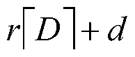
- the number of versions is based on the number of PRACHs supported by the system in the frequency domain N, the number of conversion points within 10 ms, and the density D of the PRACH, by the formula R SP
- the D version number r is obtained by the following two methods:
- the PRACH frequency domain location mapping by using the method provided by the embodiment of the present invention can make the PRACH of the same type of base station uniformly distributed in time, and can also minimize the inter-cell interference of the second type of PRACH.
- the frequency or mapping is mapped from low frequency to high frequency in the available frequency resources by the number (?) from small to large.
- One PRACH occupies 6 RBs, and the frequency bands occupied by the two adjacent PRACHs are not.
- the above mapping principle can be expressed by the following formula:
- (2) t is used to indicate which field the PRACH is in, 0 is the first field, and 1 is the second field;
- R can be configured by PRACH sent by the base station to the mobile phone, according to the version number of the preamble format combined with the density in the PRACH configuration set.
- R N is the current system bandwidth, the frequency domain
- the version number is r ( re[0,Rl] );
- the number of downlink to uplink transition points in the 10ms radio frame is N P ;
- the number of PRACH in a certain format accommodated by the domain is N t
- One PRACH occupies 6 RBs, and the frequency bands occupied by the two adjacent PRACHs in the frequency or the upper side are not represented by the following formula. : Sedon signal
- the sequence number that is, the location of the first RB available for PRACH in the frequency domain;
- R can be determined by the PRACH type sent by the base station to the mobile phone, according to the number of versions of the preamble format combined with the density in the PRACH provisioning set;
- the version number r can be directly obtained through the PRACH preparation type sent by the base station to the mobile phone.
- the number of downlink to uplink transition points in a 10ms radio frame is N SP ; the number of PRACHs in a certain format in the time domain of the half frame is N ().
- the frequency domain mapping is mapped from low frequency to high frequency in the available frequency resources by number (N) from small to large, one PRACH occupies 6 RBs, and the frequency bands occupied by the two adjacent PRACHs are not available. overlapping.
- N number
- L 1
- R can be configured by PRACH sent by the base station to the mobile phone, according to the version number of the preamble format combined with the density in the PRACH configuration set.
- R, N is the current system bandwidth, the frequency domain
- the number of downlink to uplink transition points in a 10ms radio frame is N SP ; the number of PRACHs in a certain format in the time domain of the half frame is N ().
- the frequency or mapping is mapped from low frequency to high frequency in the available frequency resources by the number (?) from small to large.
- One PRACH occupies 6 RBs, and the frequency bands occupied by the two adjacent PRACHs are not.
- the above mapping principle can be expressed by the following formula:
- R can be determined by the PRACH configuration type sent by the base station to the mobile phone according to the version number of the combination of the reamble format and the density in the PRACH configuration set; (4) the version number r can be prepared by the PRACH sent by the base station to the mobile phone. Get it directly.
- N SP the number of transition points
- N ⁇ 1 (i) the number of PRACHs in a certain format accommodated in the time domain of the field.
- the frequency or mapping is mapped from the low frequency to the high frequency in the available frequency resources by the number (N) from small to large, one PRACH occupies 6 RBs, and the frequency bands occupied by the two adjacent PRACHs are not overlapping.
- the number of downlink to uplink transition points in a 10ms radio frame is N SP ; the number of PRACHs in a certain format accommodated in the time domain of the half frame is (i).
- One physical random access channel occupies 6 resource blocks, and the frequency is The frequency bands occupied by two adjacent physical random access channels on the domain do not overlap.
- the same mapping process is used for each version number r.
- the above mapping principle can be expressed by the following formula:
- L is number of ULsub - framesfor PRACH
- the number of the PRACH is:
- the version index is r
- the time domain location is the frequency domain channel number of all PRACHs determined by ( ⁇ , , .
- N fe, , j is the version index r, and the time domain position is determined by (t , , the number of all PRACHs;
- R can be configured by PRACH from the base station to the mobile phone, according to the version number of the preamble format and density combination in the PRACH configuration set.
- R N is the current system bandwidth, the frequency domain
- N SP The number of transition points
- N (i) the number of PRACHs in a certain format contained in the time domain in the field
- Frequency or mapping for reamble format 4 by number (?) from small to large in the available frequency resources from low frequency to high frequency mapping one PRACH occupies 6 RBs, and two PRACHs in frequency or above The occupied frequency bands have no overlap.
- the PRACHs with the same version number r are mapped according to N from small to large, and the frequency is high to high frequency, and one physical random access channel occupies 6 resource blocks, and The frequency bands occupied by two adjacent physical random access channels in the frequency domain do not overlap.
- the same mapping process is used for each version number r.
- the above mapping principle can be expressed by the following formula:
- the number of the PRACH which means: the version index is r, and the time domain location is the frequency domain channel number of all PRACHs determined by ( , 4, j.)
- R can be formulated by the PRACH sent by the base station to the mobile phone, and then according to the PRACH configuration set. The number of versions of the reamble format combined with the density is determined;
- the version number r can be directly obtained through the PRACH preparation type sent by the base station to the mobile phone.
- the frequency or mapping is mapped from low frequency to high frequency in the available frequency resources for the reamble format 4 by the number (N), one PRACH occupies 6 RBs, and the two PRACHs in the frequency or upper adjacent The occupied frequency bands have no overlap.
- N the number of PRACHs with the same version number r are mapped according to N from small to large, and the frequency is high to high frequency, and one physical random access channel occupies 6 resource blocks, and The frequency bands occupied by two adjacent physical random access channels in the frequency domain do not overlap.
- the same mapping process is used for each version number r.
- the above mapping principle can be expressed by the following formula:
- the number of the PRACH is:
- the version index is r
- the time domain location is the frequency domain channel number of all PRACHs determined by ( ⁇ , , .
- N fc, is the version index r, and the time domain location is determined by the number of all PRACHs;
- R can be typed by the PRACH sent by the base station to the mobile phone, according to the version number of the preamble format combined with the density in the PRACH configuration set.
- R N is the current system bandwidth, the frequency domain
- the number of uplink transition points is N SP ; the number of PRACHs of a certain format accommodated in the time domain in the field is N ⁇ 1 (i).
- the frequency or mapping is mapped from low frequency to high frequency in the available frequency resources for the reamble format 4 by the number (N), one PRACH occupies 6 RBs, and the two PRACHs in the frequency or upper adjacent The occupied frequency bands have no overlap.
- the PRACHs with the same version number r are mapped according to N from small to large, and the frequency is high to high frequency, and one physical random access channel occupies 6 resource blocks, and The frequency bands occupied by two adjacent physical random access channels in the frequency domain do not overlap.
- the same mapping process is used for each version number r.
- the above mapping principle can be expressed by the following formula:
- the number of the PRACH is:
- the version index is r
- the time domain location is the frequency domain channel number of all PRACHs determined by ( ⁇ , , .
- the version number r can be directly obtained through the PRACH preparation type sent by the base station to the mobile phone.
- the number of downlink to uplink transition points in a 10ms radio frame is N SP ; the number of PRACHs in a certain format in the time domain of the half frame is (i).
- Embodiment 11 determines the density of PRACH as D (D can take 0.5, 1, 2, 3, 4, 5, 6 or 10
- PRACH/lOms version number
- version number is R
- the number of downlink to uplink transition points in the radio frame is the number of PRACHs in a certain format accommodated in the time domain.
- the physical random access channel with the same version number r is sequentially mapped from the two sides to the middle in the available frequency resources by N from small to large.
- mapping The method is that the number of w is mapped from the low frequency to the high frequency in the available frequency band, the odd number is mapped from the high frequency to the low frequency in the available frequency band, and one of the physical random access channels occupies 6 resource blocks, and is in frequency or on The frequency bands occupied by two adjacent physical random access channels do not overlap.
- the same mapping process is used for each version number r.
- the above mapping principle can be expressed by the following formula:
- L is number of ULsub - framesfor PRACH . [0, 1st half frame
- the number of the PRACH is:
- the version index is r
- the time domain location is determined by ( ⁇ , , all the PRACHs determined by the small number to be renumbered according to their N.
- Number to the specific frequency domain PRACH The mapping relationship of the starting RB can be
- the location of an RB that can be used for PRACH which is the total number of uplink resource blocks;
- R can be configured by PRACH from the base station to the mobile phone, according to the version number of the preamble format and density combination in the PRACH configuration set.
- the type of PRACH preparation of the machine is determined according to the number of versions of the preamble format and density combination in the PRACH configuration set;
- r N modi?
- the time and frequency position mapping results are shown in Figure 9, where (0,0)(1,1)(2,0) has the same frequency domain position; (0,2)(2,2) frequency domain The location is the same.
- the version number is r ( re[0,i?_l] );
- the number of downlink to uplink transition points in the 10ms radio frame is N SP ;
- the frequency or mapping is mapped from low frequency to high frequency in the available frequency resources for the reamble format 4 by the number (N), one PRACH occupies 6 RBs, and the two PRACHs in the frequency or upper adjacent The occupied frequency bands have no overlap.
- the physical random access channel with the same version number r is sequentially mapped from the two sides to the middle in the available frequency resources by N from small to large.
- mapping method is The even number is mapped from the low frequency to the high frequency in the available frequency band, the odd number is mapped from the high frequency to the low frequency in the available frequency band, and one of the physical random access channels occupies 6 resource blocks, and is adjacent to the frequency or the adjacent The frequency bands occupied by the two physical random access channels do not overlap.
- the same mapping procedure is used for each version number r.
- the same mapping procedure is used for each version number r.
- the above mapping principle can be expressed by the following formula:
- (1)/ is the frequency or mapping index of the preamble format 4 (frequency or upper PRACH number).
- the number of the PRACH which means: The frequency domain channel number of all PRACHs whose version index is r and whose time domain position is determined by ( , , ).
- the mapping relationship of the number of the starting RB of the PRACH to the specific frequency domain can be
- N is the total number of uplink resource blocks.
- L is the uplink subframe occupied by PRACH in this format.
- the version number r can be directly obtained through the PRACH preparation type sent by the base station to the mobile phone.
- the version number is r ( re[0,i?_l] );
- the number of downlink to uplink transition points in the 10ms radio frame is N SP ;
- the number of PRACHs in a certain format in the time domain of the field is Dj,.
- N 0,l,...,i?"D]-1
- d 0X...,[D - l, re[0,i?_l].
- mapping method is mapped to the L subframes.
- the low-frequency to high-frequency mapping in the available frequency band the odd-numbered mapping from the high frequency to the low frequency in the available frequency band
- one of the physical random access channels occupying 6 resource blocks, and the frequency or upper phase
- the frequency bands occupied by two adjacent physical random access channels do not overlap.
- the same mapping process is used for each version number r.
- the above mapping principle can be expressed by the following formula:
- the number of the PRACH which means: The version index is r, and the time domain position is determined by ( ⁇ , 4, the frequency i or channel number of all PRACHs determined. The number is to the specific frequency i or the starting RB of the upper PRACH
- the mapping relationship can be For the frequency The location of an RB that can be used for PRACH, ⁇ the total number of uplink resource blocks
- N fc,4 is the number of all PRACHs whose version index is r, and whose time domain position is determined by fe, , j;
- L is the number of uplink subframes occupied by PRACH in this format, ⁇ '- me (/) is the number of uplink subframes in the field;
- L 1
- R can be typed by the PRACH sent by the base station to the mobile phone, according to the version number of the preamble format combined with the density in the PRACH configuration set.
- R N is the current system bandwidth, the frequency domain
- the frequency or mapping is mapped from low frequency to high frequency in the available frequency resources for the reamble format 4 by the number (N).
- One PRACH occupies 6 RBs, and the two PRACHs are adjacent or adjacent to each other. The occupied frequency bands have no overlap.
- the physical random access channel with the same version number r is sequentially mapped from the two sides to the middle in the available frequency resources by N from small to large.
- mapping The method is that the number of w is mapped from the low frequency to the high frequency in the available frequency band, the odd number is mapped from the high frequency to the low frequency in the available frequency band, and one of the physical random access channels occupies 6 resource blocks, and is in frequency or on The frequency bands occupied by two adjacent physical random access channels do not overlap.
- the same mapping process is used for each version number r.
- the above mapping principle can be expressed by the following formula:
- L is number of ULsub-frames for PRACH Its towel
- LRA is the frequency or mapping index of preamble format 0 ⁇ 3 (frequency or upper
- the number of the PRACH is:
- the version index is r
- the time domain location is the frequency domain channel number of all PRACHs determined by ( ⁇ , j).
- the mapping of the number to the starting RB of the PRACH in the specific frequency domain Can be
- N R U B L is the total number of uplink resource blocks.
- L 1
- R can be determined by the PRACH type sent by the base station to the mobile phone, according to the number of versions of the reamble format and the density combination in the PRACH configuration set;
- the version number r can be directly obtained through the PRACH preparation type sent by the base station to the mobile phone.
- Example 15 Determine the density of PRACH as D (D can take 0.5, 1, 2, 3, 4, 5, 6 or 10
- Frequency or mapping for reamble format 4 According to the number (N), from low to large, in the available frequency resources, the low frequency to the high frequency are mapped, one PRACH occupies 6 RBs, and the frequency bands occupied by the two adjacent PRACHs are not overlapped.
- Reamble format 0 ⁇ 3 The physical random access channel with the same version number r is mapped from the two sides to the middle in the available frequency resources by N from small to large.
- the mapping is to the L subframes
- the version number is r.
- There are ⁇ physical random access channels, renumbered as 'v 0, l, 2, ..., -l ' according to N from small to large, then the mapping method is w is 4 in the available frequency band from the low frequency Mapping to high frequency, odd-numbered from high frequency to low frequency in the available frequency band, and one physical random access channel occupies 6 resource blocks, and two physical random access channels adjacent or adjacent to each other The occupied frequency bands have no overlap.
- the same mapping process is used for each version number r.
- Embodiment 16 Wh-PRACH has a density of D (D can take 0.5, 1, 2, 3, 4, 5, 6 or 10
- the number of versions is R;
- the number of row transition points is N SP ; the number of PRACHs of a certain format accommodated in the time domain in the field is N ⁇ i,.
- Frequency or mapping For the reamble format 0 ⁇ 4, the physical random access channel with the same version number r is sequentially mapped from the two sides to the middle in the available frequency resources by N from small to large.
- mapping The method is that the even-numbered w is mapped from the low frequency to the high frequency in the available frequency band, the odd number is mapped from the high frequency to the low frequency in the available frequency band, and one of the physical random access channels occupies 6 resource blocks, and the frequency is The frequency bands occupied by the two adjacent physical random access channels do not overlap.
- the same mapping process is used for each version number r.
- the above mapping principle can be expressed by the following formula:
- Frequency domain mapping index for preamble format 0 ⁇ 4 (on the frequency domain) is: The version index is r, and the time domain location is the frequency domain channel number of all PRACHs determined by ( ⁇ , j).
- the mapping of the number to the starting RB of the PRACH in the specific frequency domain can be
- N R U B L is the total number of uplink resource blocks.
- N fe,4, j is the number of all PRACHs whose version index is r, and whose time domain position is determined by J;
- L 1
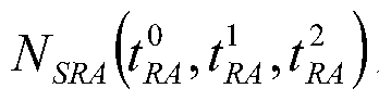
- R can be determined by the PRACH configuration type sent by the base station to the mobile phone according to the number of versions of the preamble format and density combination in the PRACH configuration set; for reamble format 4, R l SRA l SP N is the current system bandwidth, the frequency domain
- the number of row transition points is N SP ; the number of PRACHs in a certain format contained in the time domain in the field is .
- the mapping method is The even number is mapped from the low frequency to the high frequency in the available frequency band, the odd number is mapped from the high frequency to the low frequency in the available frequency band, and one of the physical random access channels occupies 6 resource blocks, and is adjacent to the frequency or the adjacent The frequency bands occupied by the two physical random access channels do not overlap.
- the same mapping procedure is used for each version number r.
- the same mapping procedure is used for each version number r.
- the above mapping principle can be expressed by the following formula:
- (1) /L(4,4, is the frequency domain mapping index of preamble format 0 ⁇ 3 (on the frequency domain)
- the number of the PRACH) is:
- the version index is r
- the time domain location is the frequency domain channel number of all PRACHs determined by ( ⁇ , j).
- the mapping of the number to the starting RB of the PRACH in the specific frequency domain Can be For the frequency
- N ⁇ -e-k ⁇ ' -el LRA otherwise The location of an RB that can be used for PRACH, which is the total number of uplink resource blocks.
- the type of PRACH formulated by the base station to the mobile phone is determined according to the number of versions of the preamble format combined with the density in the PRACH configuration set;
- r can be directly obtained through the PRACH preparation type sent by the base station to the mobile phone.
- the density of PRACH is D (D can be 0.5, 1, 2, 3, 4, 5, 6 or 10
- the physical random access channel with the same version number r is sequentially mapped from the two sides to the middle in the available frequency resources by N from small to large.
- the same mapping process is used for each version number r.
- the above mapping principle can be expressed by the following formula:
- L is number of ULsub - framesfor PRACH [0, 1st half frame
- the number of the PRACH is:
- the version index is r
- the time domain location is the frequency domain channel number of all PRACHs determined by ( ⁇ , j).
- the mapping of the number to the starting RB of the PRACH in the specific frequency domain Can be For the frequency
- the location of an RB that can be used for PRACH, ⁇ the total number of uplink resource blocks
- N fc,4 is the number of all PRACHs whose version index is r, and whose time domain position is determined by fe, , j;
- L is the number of uplink subframes occupied by PRACH in this format, ⁇ '- me (/) is the number of uplink subframes in the field;
- L 1
- R can be typed by the PRACH sent by the base station to the mobile phone, according to the version number of the preamble format combined with the density in the PRACH configuration set.
- R N is the current system bandwidth, the frequency domain
- the mapping method is w for the number of frequencies from the low frequency to the high frequency in the available frequency band, and the odd number is mapped from the high frequency to the low frequency in the available frequency band, and one of the above
- the physical random access channel occupies 6 resource blocks, and the frequency bands occupied by the two physical random access channels adjacent to each other are not overlapped.
- the same mapping process is adopted for each version number r.
- the above mapping principle may be Expressed by the following formula:
- (1) /LfcL,4 is the frequency domain mapping index of preamble format 0 ⁇ 3 (on the frequency domain)
- the number of the PRACH is:
- the version index is r
- the time domain location is the frequency domain channel number of all PRACHs determined by ( ⁇ , j).
- the mapping of the number to the starting RB of the PRACH in the specific frequency domain Can be For low frequency
- N fc,4 is the number of all PRACHs whose version index is r, and whose time domain position is determined by fe, , j;
- L is the number of uplink subframes occupied by PRACH in this format, ⁇ '- me (/) is the number of uplink subframes in the field;
- L 1
- R can be determined by the PRACH type sent by the base station to the mobile phone, according to the number of versions of the reamble format and the density combination in the PRACH configuration set;
- the version number r can be directly obtained through the PRACH preparation type sent by the base station to the mobile phone.
- the version number is r ( re[0,i?_l] );
- the number of downlink to uplink transition points in the 10ms radio frame is N SP ;
- the number of PRACHs in a certain format in the time domain of the field is .
- PRACH number When incrementing, first increment the density index, then increment the version number, that is? d , among them e [0,i?_l]. Frequency or mapping For the reamble format 0 ⁇ 4, the physical random access channel with the same version number r is sequentially mapped from the two sides to the middle in the available frequency resources by N from small to large.
- the version number is r ( re[0,i?_l] ); the number of downlink to uplink transition points in the 10ms radio frame is N SP ; the number of PRACH in a certain format in the time domain of the field For (i).
- Frequency or mapping For the reamble format 0 ⁇ 4, the physical random access channel with the same version number r is sequentially mapped from the two sides to the middle in the available frequency resources by N from small to large.
- mapping The method is w for the number In the frequency band, from the low frequency to the high frequency, the odd number is mapped from the high frequency to the low frequency in the available frequency band, and one of the physical random access channels occupies 6 resource blocks, and the two physical bodies adjacent to each other in frequency or upper The frequency bands occupied by the random access channels have no overlap.
- the same mapping process is used for each version number r.
- the above mapping principle can be expressed by the following formula:
- (1) /L(4,4, is the frequency domain mapping index of preamble format 0 ⁇ 4 (on the frequency domain)
- the number of the PRACH is:
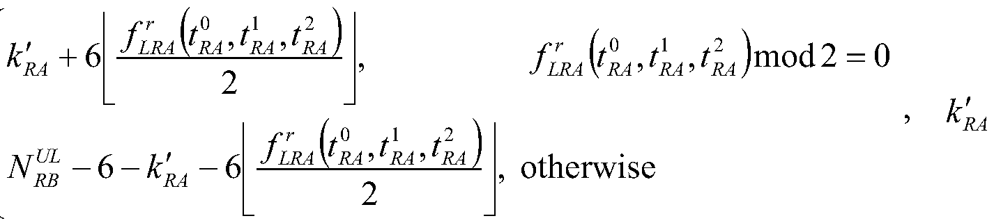
- the version index is r
- the time domain location is the frequency domain channel number of all PRACHs determined by ( ⁇ , j).
- the mapping of the number to the starting RB of the PRACH in the specific frequency domain Can be
- N RB -6-k' A -6 ⁇ otherwise The location of an RB that can be used for PRACH, which is the total number of uplink resource blocks;
- N fe,4, j is the number of all PRACHs whose version index is r, and whose time domain position is determined by fe, , j;
- L is the uplink subframe occupied by PRACH in this format.
- the number, N '- me (/) is the number of uplink subframes in the field;
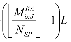
- R can be determined by the PRACH configuration type sent by the base station to the mobile phone according to the number of versions of the preamble format and the density combination in the PRACH configuration set; for the preamble format 4, R is fixed to 3, The number of PRACHs that can be accommodated in the frequency domain for the current system bandwidth;
- the version number is r ( re[0,i?_l] );
- the number of downlink to uplink transition points in the 10ms radio frame is N SP ;
- the method may be: w is an even number from the low frequency to the high frequency in the available frequency band, an odd number is mapped from the high frequency band in the available frequency band, and one of the physical random access channels occupies 6 resource blocks, And in the frequency domain The frequency bands occupied by two adjacent physical random access channels do not overlap.
- the physical random access channel with the same version number r is sequentially mapped from the two sides to the middle in the available frequency resources by N from small to large.
- mapping The method is that the even-numbered w is mapped from the low frequency to the high frequency in the available frequency band, the odd number is mapped from the high frequency to the low frequency in the available frequency band, and one of the physical random access channels occupies 6 resource blocks, and the frequency is The frequency bands occupied by the two adjacent physical random access channels do not overlap.
- the same mapping process is used for each version number r.
- the above mapping principle can be expressed by the following formula:
- L is number of ULsub - framesfor PRACH
- the real-time domain location is the result of re-numbering all PRACHs determined by ( ⁇ 4, ⁇ , according to their N from small to large.
- the first one for the frequency can be used for PRACH otherwise
- the location of the RB which is the total number of uplink resource blocks
- LRA is the frequency or mapping index of preamble format 0 ⁇ 3 (frequency or upper
- PRACH number which means: The version index is r, and the time domain position is determined by ( ⁇ , , j all PRACH, according to the result of renumbering from small to large. Number to specific frequency
- the location of an RB that can be used for PRACH which is the total number of uplink resource blocks.
- N 4 is the number of all PRACHs ( preamble format 0-3 ) whose version index is r, and the time domain position is determined by fe,4;
- L is the number of uplink subframes occupied by PRACH in this format, ⁇ '- me () is the number of uplink subframes in the field;
- R can be typed by the PRACH sent by the base station to the mobile phone, according to the version number of the preamble format combined with the density in the PRACH configuration set.
- R, N ⁇ is the current system bandwidth, frequency domain
- the type of PRACH preparation of the machine is determined according to the number of versions of the preamble format and density combination in the PRACH configuration set;
- the version number is r ( re[0,i?_l] );
- the number of downlink to uplink transition points in the 10ms radio frame is N SP ;
- the physical random access channel with the same version number r is sequentially mapped from the two sides to the middle in the available frequency resources by N from small to large.
- the method is that the number of w is 4 in the available frequency band from the low frequency to the high frequency, the odd number is mapped from the high frequency to the low frequency in the available frequency band, and one of the physical random access channels occupies 6 resource blocks, and the frequency is Or the frequency bands occupied by the two adjacent physical random access channels do not overlap.
- the same mapping process is used for each version number r.
- the above mapping principle can be expressed by the following formula:
- L is number of ULsub - framesfor PRACH
- the first one for the frequency can be used for PRACH otherwise
- the location of the RB which is the total number of uplink resource blocks
- LRA is the frequency or mapping index of the preamble format 0 ⁇ 3 (frequency or upper)
- the number of the PRACH is: The result is that the version index is r, and all PRACHs whose time domain position is determined by j are renumbered according to their V from small to large.
- the mapping relationship from the initial RB of the PRACH to the specific frequency domain can be
- the location of an RB that can be used for PRACH which is the total number of uplink resource blocks.
- N 4 is the number of all PRACHs ( preamble format 0-3 ) whose version index is r, and the time domain position is determined by fe,4;
- L is the number of uplink subframes occupied by PRACH in this format, ⁇ '- me (/) is the number of uplink subframes in the field;
- L 1 ,
- R can be typed by the PRACH sent by the base station to the mobile phone, according to the version number of the preamble format combined with the density in the PRACH configuration set.
- R, N ⁇ is the current system bandwidth, frequency domain
- the type of PRACH preparation of the machine is determined according to the number of versions of the preamble format and density combination in the PRACH configuration set;
- PRACHs with the same version number r are mapped according to N from small to large sequential frequency to high frequency, one physical random access channel occupies 6 resource blocks, and is adjacent in the frequency domain. The frequency bands occupied by the two physical random access channels do not overlap. The same mapping process is used for each version number r.
- the mapping method of the physical random access channel in the foregoing embodiment of the present invention takes the version number factor into consideration in the mapping, overcomes the problem that the same base station processes the PRACH in time, and thus can The same base station is required to process the PRACH evenly distributed in time, and at the same time, the inter-cell interference of the second type of PRACH can be minimized.
- the above modules or steps of the present invention can be implemented by a general-purpose computing device, which can be concentrated on a single computing device or distributed over a network composed of multiple computing devices.
- the computing device may be implemented by program code executable by the computing device, such that they may be stored in the storage device by the computing device, or they may be separately fabricated into individual integrated circuit modules, or they may be Multiple modules or steps are made into a single integrated circuit module.
- the invention is not limited to any particular combination of hardware and software.
- the above description is only the preferred embodiment of the present invention, and is not intended to limit the present invention, and various modifications and changes can be made to the present invention. Any modifications, equivalent substitutions, improvements, etc. made within the spirit and scope of the present invention are intended to be included within the scope of the present invention.
Landscapes
- Engineering & Computer Science (AREA)
- Signal Processing (AREA)
- Computer Networks & Wireless Communication (AREA)
- Mobile Radio Communication Systems (AREA)
- Time-Division Multiplex Systems (AREA)
Description










Claims


Priority Applications (5)
| Application Number | Priority Date | Filing Date | Title |
|---|---|---|---|
| US12/922,845 US8582673B2 (en) | 2008-03-26 | 2009-02-12 | Method for mapping physical random access channels |
| RU2010142340/07A RU2488981C2 (ru) | 2008-03-26 | 2009-02-12 | Способ преобразования физических каналов произвольного доступа |
| BRPI0910062-8A BRPI0910062B1 (pt) | 2008-03-26 | 2009-02-12 | método para mapear canal físico de acesso aleatório |
| EP09724282.0A EP2276308B1 (en) | 2008-03-26 | 2009-02-12 | Method for mapping physical random access channels |
| JP2011501092A JP5285142B2 (ja) | 2008-03-26 | 2009-02-12 | 物理ランダムアクセスチャネルのマッピング方法 |
Applications Claiming Priority (2)
| Application Number | Priority Date | Filing Date | Title |
|---|---|---|---|
| CN2008100658881A CN101252386B (zh) | 2008-03-26 | 2008-03-26 | 物理随机接入信道的映射方法 |
| CN200810065888.1 | 2008-03-26 |
Publications (1)
| Publication Number | Publication Date |
|---|---|
| WO2009117909A1 true WO2009117909A1 (zh) | 2009-10-01 |
Family
ID=39955588
Family Applications (1)
| Application Number | Title | Priority Date | Filing Date |
|---|---|---|---|
| PCT/CN2009/070413 Ceased WO2009117909A1 (zh) | 2008-03-26 | 2009-02-12 | 物理随机接入信道的映射方法 |
Country Status (7)
| Country | Link |
|---|---|
| US (1) | US8582673B2 (zh) |
| EP (1) | EP2276308B1 (zh) |
| JP (1) | JP5285142B2 (zh) |
| CN (1) | CN101252386B (zh) |
| BR (1) | BRPI0910062B1 (zh) |
| RU (1) | RU2488981C2 (zh) |
| WO (1) | WO2009117909A1 (zh) |
Cited By (1)
| Publication number | Priority date | Publication date | Assignee | Title |
|---|---|---|---|---|
| WO2012103764A1 (zh) * | 2011-01-31 | 2012-08-09 | 中兴通讯股份有限公司 | 一种无线通信系统及其上行同步信道的发送方法 |
Families Citing this family (6)
| Publication number | Priority date | Publication date | Assignee | Title |
|---|---|---|---|---|
| CN101252386B (zh) | 2008-03-26 | 2013-06-05 | 中兴通讯股份有限公司 | 物理随机接入信道的映射方法 |
| CN101267679B (zh) * | 2008-04-26 | 2013-03-27 | 中兴通讯股份有限公司 | 一种用于映射物理随机接入信道的方法 |
| CN101378595B (zh) | 2008-09-28 | 2012-05-23 | 中兴通讯股份有限公司 | 确定随机接入信道数量的方法及测量参考信号的发送方法 |
| CN101389136B (zh) * | 2008-10-24 | 2012-05-23 | 中兴通讯股份有限公司 | 物理随机接入信道的映射方法和装置 |
| CN101808330B (zh) * | 2009-02-13 | 2013-10-02 | 电信科学技术研究院 | 调整prach信道密度的方法和基站 |
| EP3393069B1 (en) * | 2015-12-18 | 2021-03-17 | LG Electronics Inc. -1- | Method and wireless device for transmitting random-access preamble by means of single-tone method |
Citations (5)
| Publication number | Priority date | Publication date | Assignee | Title |
|---|---|---|---|---|
| CN101005308A (zh) * | 2006-01-17 | 2007-07-25 | 上海原动力通信科技有限公司 | 宽带时分双工移动通信系统的物理层随机接入方法 |
| WO2007145555A1 (en) * | 2006-06-13 | 2007-12-21 | Telefonaktiebolaget Lm Ericsson (Publ) | Method and arrangement for preamble detection |
| CN101128028A (zh) * | 2006-08-17 | 2008-02-20 | 北京三星通信技术研究有限公司 | 传输随机接入信息的设备和方法 |
| CN101179364A (zh) * | 2007-12-06 | 2008-05-14 | 中兴通讯股份有限公司 | 时分双工系统中随机接入信道的发送方法 |
| CN101252386A (zh) * | 2008-03-26 | 2008-08-27 | 中兴通讯股份有限公司 | 物理随机接入信道的映射方法 |
Family Cites Families (6)
| Publication number | Priority date | Publication date | Assignee | Title |
|---|---|---|---|---|
| MY123040A (en) * | 1994-12-19 | 2006-05-31 | Salbu Res And Dev Proprietary Ltd | Multi-hop packet radio networks |
| CN1157872C (zh) * | 2000-06-02 | 2004-07-14 | 三星电子株式会社 | 码分多址移动通信系统中选择随机访问信道的方法 |
| KR101406626B1 (ko) * | 2004-06-10 | 2014-06-11 | 고도 가이샤 아이피 브릿지 1 | 무선 통신 장치, 통신 단말 장치, 기지국 장치, 무선 통신 시스템, 무선 통신 방법 및 집적 회로 |
| CN100426888C (zh) * | 2006-07-18 | 2008-10-15 | 华为技术有限公司 | 一种基于物理随机接入信道帧的时隙格式配置方法 |
| US9113325B2 (en) * | 2007-04-25 | 2015-08-18 | Texas Instruments Incorporated | Signaling of random access preamble time-frequency location in wireless networks |
| CN101335969B (zh) * | 2008-08-01 | 2012-11-28 | 中兴通讯股份有限公司 | 一种时分双工系统上行信道测量参考信号的发送方法 |
-
2008
- 2008-03-26 CN CN2008100658881A patent/CN101252386B/zh active Active
-
2009
- 2009-02-12 US US12/922,845 patent/US8582673B2/en active Active
- 2009-02-12 RU RU2010142340/07A patent/RU2488981C2/ru active
- 2009-02-12 JP JP2011501092A patent/JP5285142B2/ja active Active
- 2009-02-12 EP EP09724282.0A patent/EP2276308B1/en active Active
- 2009-02-12 WO PCT/CN2009/070413 patent/WO2009117909A1/zh not_active Ceased
- 2009-02-12 BR BRPI0910062-8A patent/BRPI0910062B1/pt active IP Right Grant
Patent Citations (5)
| Publication number | Priority date | Publication date | Assignee | Title |
|---|---|---|---|---|
| CN101005308A (zh) * | 2006-01-17 | 2007-07-25 | 上海原动力通信科技有限公司 | 宽带时分双工移动通信系统的物理层随机接入方法 |
| WO2007145555A1 (en) * | 2006-06-13 | 2007-12-21 | Telefonaktiebolaget Lm Ericsson (Publ) | Method and arrangement for preamble detection |
| CN101128028A (zh) * | 2006-08-17 | 2008-02-20 | 北京三星通信技术研究有限公司 | 传输随机接入信息的设备和方法 |
| CN101179364A (zh) * | 2007-12-06 | 2008-05-14 | 中兴通讯股份有限公司 | 时分双工系统中随机接入信道的发送方法 |
| CN101252386A (zh) * | 2008-03-26 | 2008-08-27 | 中兴通讯股份有限公司 | 物理随机接入信道的映射方法 |
Cited By (1)
| Publication number | Priority date | Publication date | Assignee | Title |
|---|---|---|---|---|
| WO2012103764A1 (zh) * | 2011-01-31 | 2012-08-09 | 中兴通讯股份有限公司 | 一种无线通信系统及其上行同步信道的发送方法 |
Also Published As
| Publication number | Publication date |
|---|---|
| BRPI0910062A2 (pt) | 2019-09-17 |
| CN101252386B (zh) | 2013-06-05 |
| EP2276308A1 (en) | 2011-01-19 |
| CN101252386A (zh) | 2008-08-27 |
| BRPI0910062B1 (pt) | 2020-10-20 |
| US8582673B2 (en) | 2013-11-12 |
| US20110019752A1 (en) | 2011-01-27 |
| RU2010142340A (ru) | 2012-05-10 |
| EP2276308A4 (en) | 2013-03-27 |
| JP5285142B2 (ja) | 2013-09-11 |
| EP2276308B1 (en) | 2014-05-07 |
| RU2488981C2 (ru) | 2013-07-27 |
| JP2011515972A (ja) | 2011-05-19 |
Similar Documents
| Publication | Publication Date | Title |
|---|---|---|
| JP7657874B2 (ja) | リソース構成方法、デバイス及び記憶媒体 | |
| CN111757488B (zh) | 随机接入信号的发送、接收方法及装置 | |
| WO2009129704A1 (zh) | 用于映射物理随机接入信道的方法 | |
| CN110447288B (zh) | 一种通信方法及装置 | |
| US11930534B2 (en) | Method and device for low latency communication in communication system | |
| WO2009117909A1 (zh) | 物理随机接入信道的映射方法 | |
| CN108886811B (zh) | 发送物理随机接入信道prach的方法、设备及系统 | |
| CN110999490B (zh) | 在无线通信系统中发送或接收无线信号的方法和设备 | |
| CN111279740A (zh) | 在无线通信系统中执行随机接入过程的方法和装置 | |
| US11324017B2 (en) | Method and apparatus for transmitting sidelink feedback information in wireless communication system | |
| CN108282876B (zh) | 一种上行传输方法、终端、网络侧设备 | |
| JP2013503581A (ja) | 参照信号の送信方法と装置 | |
| WO2018028252A1 (zh) | 一种基于扫描时间块的信息传输方法及装置 | |
| KR20200120522A (ko) | 측위를 위한 참조신호를 송수신하는 방법 및 장치 | |
| KR102196193B1 (ko) | 상향링크 참조 신호 송신 방법, 상향링크 참조 신호 수신 방법, 및 장치 | |
| CN112867151A (zh) | 资源确定方法及设备 | |
| CN101247658B (zh) | 物理随机接入信道的映射方法 | |
| CN110419190A (zh) | 在无线通信系统中由终端发送上行链路信号的方法及支持该方法的装置 | |
| WO2023087282A1 (zh) | 无线通信方法、第一终端设备及第二终端设备 | |
| CN101389136B (zh) | 物理随机接入信道的映射方法和装置 | |
| WO2010051704A1 (zh) | 资源单元映射方法 | |
| KR102182597B1 (ko) | 시간 분할 듀플렉싱을 지원하는 협대역 IoT 시스템에서 랜덤 액세스 프리앰블을 전송하기 위한 방법 및 이를 위한 장치 | |
| JP5451642B2 (ja) | フレームを用いた通信方法 | |
| CN110034900A (zh) | 一种通信方法及装置 | |
| CN101340234B (zh) | 一种用于映射物理随机接入信道的方法 |
Legal Events
| Date | Code | Title | Description |
|---|---|---|---|
| 121 | Ep: the epo has been informed by wipo that ep was designated in this application |
Ref document number: 09724282 Country of ref document: EP Kind code of ref document: A1 |
|
| WWE | Wipo information: entry into national phase |
Ref document number: 5759/CHENP/2010 Country of ref document: IN Ref document number: 2009724282 Country of ref document: EP |
|
| WWE | Wipo information: entry into national phase |
Ref document number: 12922845 Country of ref document: US |
|
| WWE | Wipo information: entry into national phase |
Ref document number: 2011501092 Country of ref document: JP |
|
| NENP | Non-entry into the national phase |
Ref country code: DE |
|
| WWE | Wipo information: entry into national phase |
Ref document number: 2010142340 Country of ref document: RU |
|
| ENP | Entry into the national phase |
Ref document number: PI0910062 Country of ref document: BR Kind code of ref document: A2 Effective date: 20100922 |