WO2009119320A1 - ステータ、モータおよび圧縮機 - Google Patents
ステータ、モータおよび圧縮機 Download PDFInfo
- Publication number
- WO2009119320A1 WO2009119320A1 PCT/JP2009/054671 JP2009054671W WO2009119320A1 WO 2009119320 A1 WO2009119320 A1 WO 2009119320A1 JP 2009054671 W JP2009054671 W JP 2009054671W WO 2009119320 A1 WO2009119320 A1 WO 2009119320A1
- Authority
- WO
- WIPO (PCT)
- Prior art keywords
- stator
- insulator
- motor
- wall portion
- coil
- Prior art date
- Legal status (The legal status is an assumption and is not a legal conclusion. Google has not performed a legal analysis and makes no representation as to the accuracy of the status listed.)
- Ceased
Links
Images





Classifications
-
- H—ELECTRICITY
- H02—GENERATION; CONVERSION OR DISTRIBUTION OF ELECTRIC POWER
- H02K—DYNAMO-ELECTRIC MACHINES
- H02K3/00—Details of windings
- H02K3/46—Fastening of windings on the stator or rotor structure
- H02K3/52—Fastening salient pole windings or connections thereto
- H02K3/521—Fastening salient pole windings or connections thereto applicable to stators only
- H02K3/522—Fastening salient pole windings or connections thereto applicable to stators only for generally annular cores with salient poles
-
- H—ELECTRICITY
- H02—GENERATION; CONVERSION OR DISTRIBUTION OF ELECTRIC POWER
- H02K—DYNAMO-ELECTRIC MACHINES
- H02K3/00—Details of windings
- H02K3/04—Windings characterised by the conductor shape, form or construction, e.g. with bar conductors
- H02K3/28—Layout of windings or of connections between windings
-
- H—ELECTRICITY
- H02—GENERATION; CONVERSION OR DISTRIBUTION OF ELECTRIC POWER
- H02K—DYNAMO-ELECTRIC MACHINES
- H02K2203/00—Specific aspects not provided for in the other groups of this subclass relating to the windings
- H02K2203/06—Machines characterised by the wiring leads, i.e. conducting wires for connecting the winding terminations
Definitions
- This invention relates to a stator, a motor, and a compressor.
- a stator includes a stator core, an insulator attached to an end face in the axial direction of the stator core, and the stator core and a coil wound around the insulator (see Japanese Patent No. 382001).
- the insulator includes an annular portion, a plurality of tooth portions protruding radially inward from the inner peripheral surface of the annular portion and arranged in the circumferential direction, and a cylindrical shape standing on an end surface in the axial direction of the annular portion And a wall.
- the connecting wire of the coil is routed on the outer peripheral surface of the wall portion in a direction (horizontal direction) parallel to the plane orthogonal to the axis as viewed from the axis orthogonal direction.
- the connecting wire of the coil is routed on the outer peripheral surface of the wall portion in a direction parallel to the plane perpendicular to the axis as viewed from the axis orthogonal direction.
- the connecting wire of the coil is routed on the outer peripheral surface of the wall portion in a direction parallel to the plane perpendicular to the axis as viewed from the axis orthogonal direction.
- an object of the present invention is to provide a stator capable of reducing the height of the wall portion of the insulator, a motor using the stator, and a compressor using the motor.
- the stator of the present invention is: A stator core; An insulator attached to the axial end surface of the stator core; A coil wound around the stator core and the insulator,
- the insulator is An annulus, A plurality of tooth portions protruding radially inward from the inner peripheral surface of the annular portion and arranged in the circumferential direction;
- the connecting wire of the coil is characterized in that it is routed on the outer peripheral surface of the wall portion in an oblique direction with respect to the plane perpendicular to the axis as viewed from the direction perpendicular to the axis.
- the crossover wire is a wire for connecting each phase of the coil.
- the connecting wire of the coil is drawn on the outer peripheral surface of the wall portion of the insulator in an oblique direction with respect to the axis orthogonal direction plane as viewed from the axis orthogonal direction.
- the plurality of crossover wires are routed around the wall portion so as not to contact each other, The height of the connecting wire from the annular portion (end surface of the stator core) can be reduced. For this reason, the axial height of the wall portion can be reduced, and the stator can be miniaturized.
- the wall portion has a plurality of steps in the height direction,
- the lead-out portion which is a portion drawn from the inner surface of the wall portion to the outer surface in the connecting wire
- the lead-in portion which is a portion drawn from the outer surface of the wall portion to the inner surface, in the connecting wire are positioned in adjacent stages. To do.
- the interval between the adjacent steps is not less than the wire diameter of the connecting wire.
- the height of the wall portion in the axial direction can be further reduced.
- the motor of the present invention A rotor,
- the stator is arranged to surround the outer peripheral side of the rotor.
- the stator since the stator is provided, the stator can be miniaturized and the motor can be miniaturized.
- the compressor of the present invention is A sealed container; A compression mechanism disposed in the sealed container; It is provided with the said motor which drives the said compression mechanism part while being arrange
- the motor since the motor is provided, the motor can be miniaturized and the compressor can be miniaturized. That is, the distance between the motor and the compression mechanism can be reduced, and the overall height of the compressor can be reduced. This can also improve the rigidity of the compressor and reduce the operating noise of the compressor.
- the connecting wire of the coil is drawn on the outer peripheral surface of the wall portion of the insulator in an oblique direction with respect to the axis orthogonal direction plane as viewed from the axis orthogonal direction.
- the height of the wall portion in the axial direction can be reduced, and the stator can be downsized.
- the stator since the stator is provided, the stator can be miniaturized and the motor can be miniaturized.
- the motor since the motor is provided, the motor can be miniaturized and the compressor can be miniaturized.
- FIG. 1 is a longitudinal sectional view showing an embodiment of a compressor according to the present invention.
- the compressor includes a sealed container 1, a compression mechanism unit 2 and a motor 3 disposed in the sealed container 1.
- This compressor is a rotary compressor.
- the suction pipe 11 is connected to the lower side of the sealed container 1 while the discharge pipe 12 is connected to the upper side of the sealed container 1.
- the refrigerant supplied from the suction pipe 11 is guided to the suction side of the compression mechanism unit 2.
- This refrigerant is carbon dioxide, but may be R410A, R22, or the like.
- the motor 3 is disposed on the upper side of the compression mechanism unit 2 and drives the compression mechanism unit 2 via the rotary shaft 4.
- the motor 3 is disposed in a high-pressure region in the sealed container 1 where the high-pressure refrigerant discharged from the compression mechanism unit 2 is filled.
- the compression mechanism section 2 includes a cylindrical main body section 20 and an upper end section 8 and a lower end section 9 that are attached to upper and lower opening ends of the main body section 20, respectively.
- the rotation shaft 4 passes through the upper end 8 and the lower end 9 and is inserted into the main body 20.
- the rotary shaft 4 is rotatably supported by a bearing 21 provided at the upper end 8 of the compression mechanism 2 and a bearing 22 provided at the lower end 9 of the compression mechanism 2.
- a crankpin 5 is provided on the rotary shaft 4 in the main body 20 and compression is performed by a compression chamber 7 formed between a piston 6 fitted and driven by the crankpin 5 and a corresponding cylinder. .
- the piston 6 rotates in an eccentric state or revolves to change the volume of the compression chamber 7.
- the motor 3 includes a cylindrical rotor 30 fixed to the rotating shaft 4 and a stator 40 disposed so as to surround the outer periphery of the rotor 30.
- the stator 40 is disposed on the radially outer side of the rotor 30 via an air gap. That is, the motor 3 is an inner rotor type motor.
- the rotor 30 has a rotor core 31 and six magnets 32 embedded in the rotor core 31 in the axial direction and arranged in the circumferential direction.
- the rotor core 31 has a cylindrical shape and is made of, for example, laminated electromagnetic steel sheets.
- the rotating shaft 4 is attached to the central hole of the rotor core 31.
- the magnet 32 is a flat permanent magnet.
- the stator 40 includes a stator core 41, insulators 51 attached to both end surfaces of the stator core 41 in the axial direction, and the stator core 41 and the coil 50 wound around the insulator 51.
- the coil 50 and the insulator 51 are partially omitted.
- the stator core 41 is made of, for example, laminated electromagnetic steel plates, and includes a cylindrical portion 45 and nine teeth portions 46 that protrude radially inward from the inner peripheral surface of the cylindrical portion 45 and are arranged in the circumferential direction.
- the stator core 41 has nine slot portions 47 that are open on the inner peripheral side and arranged in the circumferential direction. That is, the slot portion 47 is formed between the adjacent tooth portions 46.
- the coil 50 is a concentrated winding that is not wound around the plurality of tooth portions 46 but is wound around each tooth portion 46.
- the motor 3 has a so-called 6 pole 9 slot.
- the rotor 30 is rotated together with the rotating shaft 4 by an electromagnetic force generated in the stator 40 by passing an electric current through the coil 50.
- the insulator 51 is sandwiched between the stator core 41 and the coil 50 to insulate the stator core 41 and the coil 50 from each other.
- the insulator 51 stands on the annular portion 55, nine tooth portions 56 projecting radially inward from the inner peripheral surface of the annular portion 55 and arranged in the circumferential direction, and an end surface in the axial direction of the annular portion 55. And a cylindrical wall portion 57 formed.
- the annular portion 55 of the insulator 51 faces and contacts the cylindrical portion 45 of the stator core 41, and the plurality of tooth portions 56 of the insulator 51 respectively contact the plurality of teeth portions 46 of the stator core 41. They are facing each other.
- the teeth 46 of the stator core 41 and the teeth 56 of the insulator 51 have substantially the same shape when viewed from the axial direction of the stator core 41.
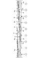
- FIG. 3 is a development view of the outer peripheral side of the insulator 51.
- the connecting wires 50a to 50c connect the phases of the coil 50.
- a three-phase current of U phase, V phase and W phase flows through each of the connecting wires 50a to 50c.
- the U-phase connecting wire 50a is shown in white
- the V-phase connecting wire 50b is shown in hatching
- the W-phase connecting wire 50c is shown in black.
- the circled numbers 1 to 9 indicate the positions of the tooth portions 46
- the circled numbers 1, 4, and 7 indicate the U-phase teeth portions 46
- the circled numbers 2, 5, and 8 indicate the V-phase teeth.
- the teeth portion 46 is indicated
- the circled numbers 3, 6, and 9 indicate the W-phase teeth portion 46.
- a plurality of protrusions 58 are provided on the outer peripheral surface of the wall portion 57 to restrict the movement of the crossover wires 50a to 50c in the axial direction.
- the interval between the protrusions 58 adjacent to each other in the height direction of the wall portion 57 is equal to or larger than the wire diameters of the connecting wires 50a to 50c.
- the wire diameter of the connecting wires 50a to 50c is, for example, 0.5 mm to 1.2 mm.
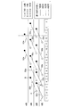
- FIG. 4 is a schematic diagram of FIG. Numbers 1 to 9 with frames in FIG. 4 correspond to numbers 1 to 9 with circles in FIG.
- the tooth portions 46 indicated by numerals 1 to 9 are referred to as first to ninth teeth portions 46.
- the wall portion 57 has a plurality of steps in the height direction, and the lead-out portion A and the pull-in portion B of the crossover wires 50a to 50c are located in steps adjacent to each other.
- the lead portion A is a portion that is drawn from the inner surface of the wall portion 57 to the outer surface of the crossover wires 50a to 50c and is indicated by a white circle in FIG.
- the pull-in portion B is a portion that is pulled into the inner surface from the outer surface of the wall portion 57 in the connecting wires 50a to 50c. This is indicated by a black circle in FIG.
- the steps of the wall portion 57 are partitioned by the protrusions 58, and the interval between the adjacent steps is equal to or greater than the wire diameter of the connecting wires 50a to 50c.
- three sets of adjacent slot portions are wound together with a coil at the same time. That is, a coil is wound around the U-phase first teeth portion 46, the W-phase third teeth portion 46, and the V-phase fifth teeth portion 46 at the same time.
- the coil is simultaneously pulled out from the first, third and fifth teeth portions 46 at the first stage of the wall portion as shown in the drawing portion A.
- the connecting lines 50a to 50c are routed from the first, third, and fifth teeth portions 46 at the same time in the diagonal direction from the first stage to the second stage.
- the coils 50a to 50c are simultaneously drawn into the fourth, sixth and eighth teeth portions 46, respectively, as shown in the drawing portion B from the second stage.
- a coil is wound around the fourth, sixth and eighth teeth portions 46 at the same time. Thereafter, in the same manner, coils are wound around all the tooth portions 46 while the connecting wires 50a to 50c are routed in an oblique direction.
- the first time is indicated by a solid line
- the second time is indicated by a dotted line
- the third time is indicated by a one-dot chain line.
- the connecting wires 50a to 50c of the coil 50 are formed on the outer peripheral surface of the wall portion 57 of the insulator 51 in an oblique direction with respect to the plane orthogonal to the axis as viewed from the axis orthogonal direction. Since the adjacent slot portions 47 in the slot portion 47 of the stator core 41 are set as one set, and when the coils 50 are simultaneously wound around the plurality of crossover wires 50a to 50c, When routed around the wall portion 57 so as not to contact each other, the height of the connecting wires 50a to 50c from the annular portion 55 (the end surface of the stator core 41) can be reduced. For this reason, the axial height of the wall portion 57 can be reduced, and the stator 40 can be downsized.
- the height of the wall portion 57 can be set to four levels in the 9-slot stator by drawing the connecting wires 50a to 50c obliquely.
- the lead-out portion A and the pull-in portion B of the crossover wires 50a to 50c are located in adjacent stages, so that the axial height of the wall portion 57 is further reduced. it can.
- the stator 40 since the stator 40 is provided, the stator 40 can be reduced in size, and the motor 3 can be reduced in size.
- the motor 3 since the motor 3 is provided, the motor 3 can be reduced in size, and the compressor can be reduced in size. That is, the distance between the motor 3 and the compression mechanism unit 2 can be reduced, and the overall height of the compressor can be reduced. This can also improve the rigidity of the compressor and reduce the operating noise of the compressor.
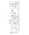
- FIG. 6 shows a second embodiment of the stator of the present invention. The difference from the first embodiment (FIG. 4) will be described. In the second embodiment, the number of teeth portions (slot portions) of the stator core is different. Since other structures are the same as those of the first embodiment, description thereof is omitted.
- the stator according to the second embodiment shows a state in which the connecting wires 50a to 50c are routed in the case of 12 slots.
- the first time is indicated by a solid line
- the second time is indicated by a dotted line
- the third time is indicated by a one-dot chain line
- the fourth time is indicated by a two-dot chain line.
- the method of routing the connecting wires 50a to 50c is the same as that in the first embodiment.
- the crossover wires 50a to 50c are routed in an oblique direction so that the height of the insulator wall is lowered to four steps. Can do.
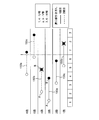
- FIG. 8 shows a third embodiment of the stator of the present invention. The difference from the first embodiment (FIG. 4) will be described. In the third embodiment, the number of teeth portions (slot portions) of the stator core is different. Since other structures are the same as those of the first embodiment, description thereof is omitted.
- the stator according to the third embodiment shows a state in which the connecting wires 50a to 50c are routed in the case of 6 slots.
- the first is shown by the solid line and the second is shown by the dotted line.
- the method of routing the connecting wires 50a to 50c is the same as that in the first embodiment.
- the jumper wires 50a to 50c are drawn in an oblique direction so that the height of the insulator wall is lowered to three steps. Can do.
- the present invention is not limited to the above-described embodiment.
- a scroll type or a reciprocating type may be used in addition to the rotary type.
- the number of teeth (slots) of the stator core can be increased or decreased.
Landscapes
- Engineering & Computer Science (AREA)
- Power Engineering (AREA)
- Insulation, Fastening Of Motor, Generator Windings (AREA)
- Windings For Motors And Generators (AREA)
Abstract
インシュレータの壁部の高さを低減できるステータを提供する。コイル50の渡り線50a~50cは、インシュレータ51の壁部57の外周面に、軸直交方向からみて、軸直交方向平面に対して斜め方向に引き回されている。
Description
この発明は、ステータ、モータおよび圧縮機に関する。
従来、ステータとしては、ステータコアと、このステータコアの軸方向の端面に取り付けられたインシュレータと、上記ステータコアおよび上記インシュレータに巻回されたコイルとを備えたものがある(特許第3824001号公報参照)。
上記インシュレータは、環状部と、この環状部の内周面から径方向内側に突出すると共に周方向に配列された複数の歯部と、この環状部の軸方向の端面に立てられた円筒状の壁部とを有する。
上記コイルの渡り線は、上記壁部の外周面に、軸直交方向からみて、軸直交方向平面に対して平行な方向(水平方向)に引き回されている。
しかしながら、上記従来のステータでは、上記コイルの渡り線は、上記壁部の外周面に、軸直交方向からみて、軸直交方向平面に対して平行な方向に引き回されているので、上記ステータコアのスロット部が多い場合に、隣り合うスロット部を一組として複数組を、同時に、上記コイルにて巻回す際に、複数の上記渡り線を、互いに接触しないように、上記壁部に引き回すとき、上記渡り線の上記環状部(上記ステータコア端面)からの高さが高くなる問題があった。このため、上記壁部の軸方向の高さを高くしなければならなかった。
そこで、この発明の課題は、インシュレータの壁部の高さを低減できるステータ、このステータを用いたモータ、および、このモータを用いた圧縮機を提供することにある。
上記課題を解決するため、この発明のステータは、
ステータコアと、
このステータコアの軸方向の端面に取り付けられたインシュレータと、
上記ステータコアおよび上記インシュレータに巻回されたコイルと
を備え、
上記インシュレータは、
環状部と、
この環状部の内周面から径方向内側に突出すると共に周方向に配列された複数の歯部と、
この環状部の軸方向の端面に立てられた円筒状の壁部と
を有し、
上記コイルの渡り線は、上記壁部の外周面に、軸直交方向からみて、軸直交方向平面に対して斜め方向に引き回されていることを特徴としている。
ステータコアと、
このステータコアの軸方向の端面に取り付けられたインシュレータと、
上記ステータコアおよび上記インシュレータに巻回されたコイルと
を備え、
上記インシュレータは、
環状部と、
この環状部の内周面から径方向内側に突出すると共に周方向に配列された複数の歯部と、
この環状部の軸方向の端面に立てられた円筒状の壁部と
を有し、
上記コイルの渡り線は、上記壁部の外周面に、軸直交方向からみて、軸直交方向平面に対して斜め方向に引き回されていることを特徴としている。
ここで、上記渡り線とは、上記コイルの各相を接続する配線である。
この発明のステータによれば、上記コイルの上記渡り線は、上記インシュレータの上記壁部の外周面に、軸直交方向からみて、軸直交方向平面に対して斜め方向に引き回されているので、上記ステータコアのスロット部において隣り合うスロット部を一組として複数組を、同時に、上記コイルにて巻回す際に、複数の上記渡り線を、互いに接触しないように、上記壁部に引き回すとき、上記渡り線の上記環状部(上記ステータコア端面)からの高さを低くできる。このため、上記壁部の軸方向の高さを低減できて、ステータの小型化を図ることができる。
また、一実施形態のステータでは、
上記壁部は、高さ方向に、複数の段を有し、
上記渡り線における上記壁部の内面から外面に引き出される部分である引き出し部と、上記渡り線における上記壁部の外面から内面に引き入れられる部分である引き入れ部とは、互いに、隣り合う段に位置する。
上記壁部は、高さ方向に、複数の段を有し、
上記渡り線における上記壁部の内面から外面に引き出される部分である引き出し部と、上記渡り線における上記壁部の外面から内面に引き入れられる部分である引き入れ部とは、互いに、隣り合う段に位置する。
ここで、上記隣り合う段の間の間隔は、上記渡り線の線径以上である。
この実施形態のステータによれば、上記渡り線の引き出し部および引き入れ部は、互いに、隣り合う段に位置するので、上記壁部の軸方向の高さを一層低減できる。
また、この発明のモータは、
ロータと、
このロータの外周側を囲むように配置された上記ステータと
を備えることを特徴としている。
ロータと、
このロータの外周側を囲むように配置された上記ステータと
を備えることを特徴としている。
この発明のモータによれば、上記ステータを備えるので、上記ステータを小型にできて、モータの小型化を図ることができる。
また、この発明の圧縮機は、
密閉容器と、
この密閉容器内に配置された圧縮機構部と、
上記密閉容器内に配置されると共に上記圧縮機構部を駆動する上記モータと
を備えることを特徴としている。
密閉容器と、
この密閉容器内に配置された圧縮機構部と、
上記密閉容器内に配置されると共に上記圧縮機構部を駆動する上記モータと
を備えることを特徴としている。
この発明の圧縮機によれば、上記モータを備えるので、上記モータを小型にできて、圧縮機の小型化を図ることができる。つまり、上記モータと上記圧縮機構部との距離を近づけることができて、圧縮機の全高を低くできる。また、これにより、圧縮機の剛性を向上できて、圧縮機の運転音を低減できる。
この発明のステータによれば、上記コイルの上記渡り線は、上記インシュレータの上記壁部の外周面に、軸直交方向からみて、軸直交方向平面に対して斜め方向に引き回されているので、上記壁部の軸方向の高さを低減できて、ステータの小型化を図ることができる。
この発明のモータによれば、上記ステータを備えるので、上記ステータを小型にできて、モータの小型化を図ることができる。
この発明の圧縮機によれば、上記モータを備えるので、上記モータを小型にできて、圧縮機の小型化を図ることができる。
以下、この発明を図示の実施の形態により詳細に説明する。
(第1の実施形態)
図1は、この発明の圧縮機の一実施形態である縦断面図を示している。この圧縮機は、密閉容器1と、この密閉容器1内に配置された圧縮機構部2およびモータ3とを備えている。この圧縮機は、ロータリ圧縮機である。
図1は、この発明の圧縮機の一実施形態である縦断面図を示している。この圧縮機は、密閉容器1と、この密閉容器1内に配置された圧縮機構部2およびモータ3とを備えている。この圧縮機は、ロータリ圧縮機である。
上記密閉容器1の下側側方に、吸入管11を接続する一方、密閉容器1の上側に吐出管12を接続している。上記吸入管11から供給される冷媒は、上記圧縮機構部2の吸込側に導かれる。この冷媒は、二酸化炭素であるが、R410AやR22等であってもよい。
上記モータ3は、上記圧縮機構部2の上側に配置され、上記圧縮機構部2を回転軸4を介して駆動する。上記モータ3は、上記圧縮機構部2から吐出された高圧の冷媒が満たされる上記密閉容器1内の高圧領域に配置されている。
上記圧縮機構部2は、シリンダ状の本体部20と、この本体部20の上下の開口端のそれぞれに取り付けられた上端部8および下端部9とを備える。
上記回転軸4は、上端部8および下端部9を貫通して、本体部20の内部に挿入されている。上記回転軸4は、圧縮機構部2の上端部8に設けられた軸受21と、圧縮機構部2の下端部9に設けられた軸受22により回転自在に支持されている。
上記本体部20内の回転軸4にクランクピン5が設けられ、このクランクピン5に嵌合されて駆動されるピストン6とそれに対応するシリンダとの間に形成された圧縮室7により圧縮を行う。ピストン6は、偏芯した状態で回転し、または、公転運動を行い、圧縮室7の容積を変化させる。
図1と図2に示すように、上記モータ3は、上記回転軸4に固定された円筒形状のロータ30と、上記ロータ30の外周側を囲むように配置されたステータ40とを有する。上記ステータ40は、上記ロータ30の径方向外側にエアギャップを介して配置されている。つまり、上記モータ3は、インナーロータ型のモータである。
上記ロータ30は、ロータコア31と、このロータコア31に軸方向に埋め込まれると共に周方向に配列された6つの磁石32とを有する。
上記ロータコア31は、円筒形状であり、例えば積層された電磁鋼板からなる。上記ロータコア31の中央の孔部には、上記回転軸4が取り付けられている。上記磁石32は、平板状の永久磁石である。
上記ステータ40は、ステータコア41と、このステータコア41の軸方向の両端面に取り付けられたインシュレータ51と、上記ステータコア41および上記インシュレータ51に巻回されたコイル50とを有する。なお、図2では、上記コイル50および上記インシュレータ51を一部省略して描いている。
上記ステータコア41は、例えば積層された電磁鋼板からなり、円筒部45と、この円筒部45の内周面から径方向内側に突出すると共に周方向に配列された9つのティース部46とを有する。
上記ステータコア41は、内周側に開口すると共に周方向に配列された9つのスロット部47を有する。つまり、このスロット部47は、隣り合う上記ティース部46の間に形成される。
上記コイル50は、複数の上記ティース部46に渡って巻かれておらず各ティース部46に巻かれている集中巻きである。上記モータ3は、いわゆる6極9スロットである。上記コイル50に電流を流して上記ステータ40に発生する電磁力によって、上記ロータ30を、上記回転軸4と共に、回転させる。
上記インシュレータ51は、上記ステータコア41と上記コイル50との間に挟持され、上記ステータコア41と上記コイル50とを絶縁している。
上記インシュレータ51は、環状部55と、この環状部55の内周面から径方向内側に突出すると共に周方向に配列された9つの歯部56と、上記環状部55の軸方向の端面に立てられた円筒状の壁部57とを有している。
上記インシュレータ51の上記環状部55は、上記ステータコア41の上記円筒部45に対向して接触し、上記インシュレータ51の上記複数の歯部56は、それぞれ、上記ステータコア41の上記複数のティース部46に対向して接触している。
上記ステータコア41の上記ティース部46と、上記インシュレータ51の上記歯部56とは、上記ステータコア41の軸方向からみて、略同じ形状である。
図3に示すように、上記壁部57の外周面には、上記コイル50の渡り線50a,50b,50cが周方向に這わされている。図3は、上記インシュレータ51の外周側の展開図である。
上記渡り線50a~50cは、上記コイル50の各相を接続する。この渡り線50a~50cには、それぞれ、U相、V相およびW相の三相の電流が流される。図3では、U相の渡り線50aを白抜きで示し、V相の渡り線50bをハッチングで示し、W相の渡り線50cを黒塗りで示す。また、丸付き数字1~9は、ティース部46の位置を示し、丸付き数字1,4,7は、U相のティース部46を指し、丸付き数字2,5,8は、V相のティース部46を指し、丸付き数字3,6,9は、W相のティース部46を指す。
上記壁部57の外周面には、上記渡り線50a~50cの軸方向への移動を規制する複数の突起部58が設けられている。上記壁部57の高さ方向に隣り合う上記突起部58の間の間隔は、上記渡り線50a~50cの線径以上である。上記渡り線50a~50cの線径は、例えば、0.5mm~1.2mmである。
図3と図4に示すように、上記渡り線50a~50cは、上記壁部57の外周面に、軸直交方向からみて、軸直交方向平面に対して斜め方向に引き回されている。図4は、図3の模式図である。図4の枠付き数字1~9は、図3の丸付き数字1~9に対応している。以下、数字1~9にて示すティース部46を、第1~第9のティース部46という。
上記壁部57は、高さ方向に、複数の段を有し、上記渡り線50a~50cの引き出し部Aおよび引き入れ部Bは、互いに、隣り合う段に位置する。
上記引き出し部Aは、上記渡り線50a~50cにおける上記壁部57の内面から外面に引き出される部分であり、図4中の白丸で示される。
上記引き入れ部Bは、上記渡り線50a~50cにおける上記壁部57の外面から内面に引き入れられる部分である。図4中の黒丸で示される。
上記壁部57の段は、上記突起部58によって、区画されており、上記隣り合う段の間の間隔は、上記渡り線50a~50cの線径以上である。
上記渡り線50a~50cの引き回し方法を説明する。
図4に示すように、隣り合うスロット部を一組として3組を、同時に、コイルにて巻回す。つまり、U相の第1のティース部46、W相の第3のティース部46、および、V相の第5のティース部46に、同時に、コイルを巻く。
その後、第1、第3および第5のティース部46から、壁部の1段目に、引き出し部Aに示すように、同時にコイルを引き出す。そして、実線に示すように、渡り線50a~50cを、1段目から2段目の斜め方向に、同時に引き回して、第1、第3および第5のティース部46から引き回された渡り線50a~50cを、それぞれ、第4、第6および第8のティース部46に、2段目から、引き入れ部Bに示すように、同時にコイルを引き入れる。
そして、第4、第6および第8のティース部46に、同時に、コイルを巻く。その後は、同様にして、渡り線50a~50cを斜め方向に引き回しつつ、全てのティース部46にコイルを巻く。図4では、渡り線50a~50cの引き回しの順番について、実線にて1回目を示し、点線にて2回目を示し、一点鎖線にて3回目を示す。
上記構成のステータ40によれば、上記コイル50の上記渡り線50a~50cは、上記インシュレータ51の上記壁部57の外周面に、軸直交方向からみて、軸直交方向平面に対して斜め方向に引き回されているので、上記ステータコア41のスロット部47において隣り合うスロット部47を一組として3組を、同時に、上記コイル50にて巻回す際に、複数の上記渡り線50a~50cを、互いに接触しないように、上記壁部57に引き回すとき、上記渡り線50a~50cの上記環状部55(上記ステータコア41の端面)からの高さを低くできる。このため、上記壁部57の軸方向の高さを低減できて、ステータ40の小型化を図ることができる。
つまり、図4に示すように、渡り線50a~50cを斜め方向に引き回すことで、9スロットのステータでは、壁部57の高さを4段とすることができる。
これに対して、図5の比較例に示すように、隣り合うスロット部を一組として3組を、同時に、コイルにて巻回す際に、複数の渡り線150a~150cを、互いに接触しないように、インシュレータの壁部に、水平方向に引き回すとき、渡り線150a~150cのステータコア端面からの高さが高くなる。つまり、渡り線150a~150cを水平方向に引き回すことで、9スロットのステータでは、壁部の高さが6段となり、ステータが大型になる問題がある。
また、上記構成のステータ40によれば、上記渡り線50a~50cの引き出し部Aおよび引き入れ部Bは、互いに、隣り合う段に位置するので、上記壁部57の軸方向の高さを一層低減できる。
また、上記構成のモータ3によれば、上記ステータ40を備えるので、上記ステータ40を小型にできて、モータ3の小型化を図ることができる。
また、上記構成の圧縮機によれば、上記モータ3を備えるので、上記モータ3を小型にできて、圧縮機の小型化を図ることができる。つまり、上記モータ3と上記圧縮機構部2との距離を近づけることができて、圧縮機の全高を低くできる。また、これにより、圧縮機の剛性を向上できて、圧縮機の運転音を低減できる。
(第2の実施形態)
図6は、この発明のステータの第2の実施形態を示している。上記第1の実施形態(図4)と相違する点を説明すると、この第2の実施形態では、ステータコアのティース部(スロット部)の数量が相違する。なお、その他の構造は、上記第1の実施形態と同じであるため、その説明を省略する。
図6は、この発明のステータの第2の実施形態を示している。上記第1の実施形態(図4)と相違する点を説明すると、この第2の実施形態では、ステータコアのティース部(スロット部)の数量が相違する。なお、その他の構造は、上記第1の実施形態と同じであるため、その説明を省略する。
図6に示すように、この第2の実施形態のステータでは、12スロットの場合の渡り線50a~50cの引き回し状態を示す。渡り線50a~50cの引き回しの順番について、実線にて1回目を示し、点線にて2回目を示し、一点鎖線にて3回目を示し、二点鎖線にて4回目を示す。渡り線50a~50cの引き回し方法は、上記第1の実施形態と同様である。
したがって、隣り合うスロット部を一組として3組を、同時に、コイルにて巻回す際に、渡り線50a~50cを斜め方向に引き回すことで、インシュレータ壁部の高さを4段と低くすることができる。
これに対して、図7の比較例に示すように、渡り線150a~150cを水平方向に引き回すと、インシュレータ壁部の高さが6段と高くなる。
(第3の実施形態)
図8は、この発明のステータの第3の実施形態を示している。上記第1の実施形態(図4)と相違する点を説明すると、この第3の実施形態では、ステータコアのティース部(スロット部)の数量が相違する。なお、その他の構造は、上記第1の実施形態と同じであるため、その説明を省略する。
図8は、この発明のステータの第3の実施形態を示している。上記第1の実施形態(図4)と相違する点を説明すると、この第3の実施形態では、ステータコアのティース部(スロット部)の数量が相違する。なお、その他の構造は、上記第1の実施形態と同じであるため、その説明を省略する。
図8に示すように、この第3の実施形態のステータでは、6スロットの場合の渡り線50a~50cの引き回し状態を示す。渡り線50a~50cの引き回しの順番について、実線にて1回目を示し、点線にて2回目を示す。渡り線50a~50cの引き回し方法は、上記第1の実施形態と同様である。
したがって、隣り合うスロット部を一組として3組を、同時に、コイルにて巻回す際に、渡り線50a~50cを斜め方向に引き回すことで、インシュレータ壁部の高さを3段と低くすることができる。
これに対して、図9の比較例に示すように、渡り線150a~150cを水平方向に引き回すと、インシュレータ壁部の高さを6段と高くしても、渡り線150a~150cを引き回すことができない。つまり、図9中の×印に示すように、1回目のV相の渡り線150bの引き入れ部Bと、2回目のV相の渡り線150bの引き入れ部Bとが、他の渡り線と接触する。
なお、この発明は上述の実施形態に限定されない。例えば、圧縮機構部として、ロータリタイプ以外に、スクロールタイプやレシプロタイプを用いてもよい。また、ステータコアのティース部(スロット部)の数量の増減は、自由である。
1 密閉容器
2 圧縮機構部
3 モータ
4 回転軸
5 クランクピン
6 ピストン
7 圧縮室
8 上端部
9 下端部
11 吸入管
12 吐出管
20 本体部
21,22 軸受
30 ロータ
31 ロータコア
32 磁石
40 ステータ
41 ステータコア
45 円筒部
46 ティース部
47 スロット部
50 コイル
50a (U相の)渡り線
50b (V相の)渡り線
50c (W相の)渡り線
51 インシュレータ
55 環状部
56 歯部
57 壁部
58 突起部
A 引き出し部
B 引き入れ部
2 圧縮機構部
3 モータ
4 回転軸
5 クランクピン
6 ピストン
7 圧縮室
8 上端部
9 下端部
11 吸入管
12 吐出管
20 本体部
21,22 軸受
30 ロータ
31 ロータコア
32 磁石
40 ステータ
41 ステータコア
45 円筒部
46 ティース部
47 スロット部
50 コイル
50a (U相の)渡り線
50b (V相の)渡り線
50c (W相の)渡り線
51 インシュレータ
55 環状部
56 歯部
57 壁部
58 突起部
A 引き出し部
B 引き入れ部
Claims (4)
- ステータコア(41)と、
このステータコア(41)の軸方向の端面に取り付けられたインシュレータ(51)と、
上記ステータコア(41)および上記インシュレータ(51)に巻回されたコイル(50)と
を備え、
上記インシュレータ(51)は、
環状部(55)と、
この環状部(55)の内周面から径方向内側に突出すると共に周方向に配列された複数の歯部(56)と、
この環状部(55)の軸方向の端面に立てられた円筒状の壁部(57)と
を有し、
上記コイル(50)の渡り線(50a,50b,50c)は、上記壁部(57)の外周面に、軸直交方向からみて、軸直交方向平面に対して斜め方向に引き回されていることを特徴とするステータ。 - 請求項1に記載のステータにおいて、
上記壁部(57)は、高さ方向に、複数の段を有し、
上記渡り線(50a,50b,50c)における上記壁部(57)の内面から外面に引き出される部分である引き出し部(A)と、上記渡り線(50a,50b,50c)における上記壁部(57)の外面から内面に引き入れられる部分である引き入れ部(B)とは、互いに、隣り合う段に位置することを特徴とするステータ。 - ロータ(30)と、
このロータ(30)の外周側を囲むように配置された請求項1または2に記載のステータ(40)と
を備えることを特徴とするモータ。 - 密閉容器(1)と、
この密閉容器(1)内に配置された圧縮機構部(2)と、
上記密閉容器(1)内に配置されると共に上記圧縮機構部(2)を駆動する請求項3に記載のモータ(3)と
を備えることを特徴とする圧縮機。
Priority Applications (4)
| Application Number | Priority Date | Filing Date | Title |
|---|---|---|---|
| ES09724320.8T ES2671025T3 (es) | 2008-03-28 | 2009-03-11 | Estator, motor y compresor |
| CN2009801111757A CN101981784B (zh) | 2008-03-28 | 2009-03-11 | 定子、电动机及压缩机 |
| US12/934,480 US8373320B2 (en) | 2008-03-28 | 2009-03-11 | Stator, motor, and compressor |
| EP09724320.8A EP2259410B1 (en) | 2008-03-28 | 2009-03-11 | Stator, motor, and compressor |
Applications Claiming Priority (2)
| Application Number | Priority Date | Filing Date | Title |
|---|---|---|---|
| JP2008-085742 | 2008-03-28 | ||
| JP2008085742A JP4450086B2 (ja) | 2008-03-28 | 2008-03-28 | ステータ、モータおよび圧縮機 |
Publications (1)
| Publication Number | Publication Date |
|---|---|
| WO2009119320A1 true WO2009119320A1 (ja) | 2009-10-01 |
Family
ID=41113518
Family Applications (1)
| Application Number | Title | Priority Date | Filing Date |
|---|---|---|---|
| PCT/JP2009/054671 Ceased WO2009119320A1 (ja) | 2008-03-28 | 2009-03-11 | ステータ、モータおよび圧縮機 |
Country Status (6)
| Country | Link |
|---|---|
| US (1) | US8373320B2 (ja) |
| EP (1) | EP2259410B1 (ja) |
| JP (1) | JP4450086B2 (ja) |
| CN (1) | CN101981784B (ja) |
| ES (1) | ES2671025T3 (ja) |
| WO (1) | WO2009119320A1 (ja) |
Cited By (1)
| Publication number | Priority date | Publication date | Assignee | Title |
|---|---|---|---|---|
| GB2466090A (en) * | 2008-12-12 | 2010-06-16 | Zhongshan Broad Ocean Motor Co | Interconnecting concentrated stator windings |
Families Citing this family (6)
| Publication number | Priority date | Publication date | Assignee | Title |
|---|---|---|---|---|
| JP2013118750A (ja) * | 2011-12-02 | 2013-06-13 | Hitachi Ltd | アキシャルギャップ型回転電機及びその製造方法 |
| EP2662954B1 (en) * | 2012-05-09 | 2022-06-29 | LG Innotek Co., Ltd. | Motor |
| JP7004164B2 (ja) * | 2018-03-30 | 2022-01-21 | 株式会社豊田自動織機 | 回転電機のステータ、回転電機、及び回転電機のステータの製造方法 |
| US10971964B2 (en) | 2018-08-23 | 2021-04-06 | Dayton-Phoenix Group, Inc. | Stator for a multiphase electric motor and method of making |
| CN112436641B (zh) * | 2019-08-26 | 2021-11-16 | 安徽美芝精密制造有限公司 | 定子组件、电机、压缩机及制冷设备 |
| CN117060610A (zh) * | 2020-07-24 | 2023-11-14 | 安徽威灵汽车部件有限公司 | 定子、电机、流体泵和车辆 |
Citations (3)
| Publication number | Priority date | Publication date | Assignee | Title |
|---|---|---|---|---|
| JP2003348783A (ja) * | 2002-05-24 | 2003-12-05 | Hitachi Home & Life Solutions Inc | 密閉型電動圧縮機 |
| JP3824001B2 (ja) | 2004-02-06 | 2006-09-20 | ダイキン工業株式会社 | 電動機の固定子 |
| JP2007110848A (ja) * | 2005-10-14 | 2007-04-26 | Odawara Engineering Co Ltd | 3相9極のステータ及びそのステータコイル巻線方法 |
Family Cites Families (8)
| Publication number | Priority date | Publication date | Assignee | Title |
|---|---|---|---|---|
| JP4005169B2 (ja) * | 1997-04-11 | 2007-11-07 | 東芝キヤリア株式会社 | 圧縮機 |
| JP3741600B2 (ja) * | 2000-09-21 | 2006-02-01 | 三菱電機株式会社 | 電動機の固定子 |
| DE10143217C1 (de) * | 2001-09-04 | 2003-02-27 | Compact Dynamics Gmbh | Wanderfeldmaschine |
| ES2535512T3 (es) | 2004-02-06 | 2015-05-12 | Daikin Industries, Ltd. | Estátor de motor eléctrico |
| JP4710047B2 (ja) * | 2005-10-14 | 2011-06-29 | 康雄 飯島 | バリアブルリラクタンス型角度検出器 |
| DE102007005357A1 (de) * | 2006-02-03 | 2007-10-04 | Asmo Co., Ltd., Kosai | Stator |
| JP2008167604A (ja) * | 2006-12-28 | 2008-07-17 | Ichinomiya Denki:Kk | インナーロータ型モールドブラシレスモータのステータ |
| JP2009033836A (ja) * | 2007-07-26 | 2009-02-12 | Aisin Seiki Co Ltd | モータのヒュージング構造 |
-
2008
- 2008-03-28 JP JP2008085742A patent/JP4450086B2/ja active Active
-
2009
- 2009-03-11 US US12/934,480 patent/US8373320B2/en active Active
- 2009-03-11 WO PCT/JP2009/054671 patent/WO2009119320A1/ja not_active Ceased
- 2009-03-11 EP EP09724320.8A patent/EP2259410B1/en active Active
- 2009-03-11 CN CN2009801111757A patent/CN101981784B/zh active Active
- 2009-03-11 ES ES09724320.8T patent/ES2671025T3/es active Active
Patent Citations (3)
| Publication number | Priority date | Publication date | Assignee | Title |
|---|---|---|---|---|
| JP2003348783A (ja) * | 2002-05-24 | 2003-12-05 | Hitachi Home & Life Solutions Inc | 密閉型電動圧縮機 |
| JP3824001B2 (ja) | 2004-02-06 | 2006-09-20 | ダイキン工業株式会社 | 電動機の固定子 |
| JP2007110848A (ja) * | 2005-10-14 | 2007-04-26 | Odawara Engineering Co Ltd | 3相9極のステータ及びそのステータコイル巻線方法 |
Cited By (1)
| Publication number | Priority date | Publication date | Assignee | Title |
|---|---|---|---|---|
| GB2466090A (en) * | 2008-12-12 | 2010-06-16 | Zhongshan Broad Ocean Motor Co | Interconnecting concentrated stator windings |
Also Published As
| Publication number | Publication date |
|---|---|
| EP2259410A1 (en) | 2010-12-08 |
| CN101981784B (zh) | 2013-05-08 |
| EP2259410A4 (en) | 2016-07-06 |
| EP2259410B1 (en) | 2018-05-16 |
| CN101981784A (zh) | 2011-02-23 |
| US20110014068A1 (en) | 2011-01-20 |
| US8373320B2 (en) | 2013-02-12 |
| ES2671025T3 (es) | 2018-06-04 |
| JP4450086B2 (ja) | 2010-04-14 |
| JP2009240118A (ja) | 2009-10-15 |
Similar Documents
| Publication | Publication Date | Title |
|---|---|---|
| JP4450086B2 (ja) | ステータ、モータおよび圧縮機 | |
| US8106557B2 (en) | Permanent magnet synchronous motor and hermetic compressor | |
| US20100194228A1 (en) | Motor and compressor technology | |
| JP6107386B2 (ja) | モータ及び圧縮機 | |
| JP2017163825A (ja) | モータ及びそのステータ | |
| US20220166270A1 (en) | Motor, compressor, and air conditioner | |
| US10797551B2 (en) | Motor and compressor having insulator and stator core with non-overlapping grooves | |
| CN102738917B (zh) | 电动马达以及使用该电动马达的马达驱动压缩机 | |
| JP4195705B2 (ja) | ステータとこれを有する電気モーター | |
| US8405274B2 (en) | Motor stator and phase coil preform | |
| US9698644B2 (en) | Electric compressor for vehicle | |
| JP7285097B2 (ja) | オープン巻線型モーター、圧縮機、および冷凍サイクル装置 | |
| CN110768403B (zh) | 定子组件、永磁电机、压缩机、风机和空调器 | |
| WO2022202786A1 (ja) | 電動機、および圧縮機 | |
| JP4957614B2 (ja) | ステータ、モータおよび圧縮機 | |
| WO2022071025A1 (ja) | インシュレータ及びモータ | |
| JP5953933B2 (ja) | ステータおよび圧縮機 | |
| EP3598612B1 (en) | Stator and electric motor equipped with said stator | |
| JP2011102543A (ja) | 圧縮機 | |
| JP2008109794A (ja) | アキシャルギャップ型モータおよびそれを用いた圧縮機 | |
| JP2010166661A (ja) | 回転電機、回転電機の駆動方法及び、圧縮機 | |
| JP7622882B1 (ja) | モータおよび圧縮機 | |
| JP2012139045A (ja) | ロータ、モータおよび圧縮機 | |
| WO2025084045A1 (ja) | モータ及びそれを備えた電動圧縮機 | |
| JP2026059896A (ja) | モータ、圧縮機、及び冷凍装置 |
Legal Events
| Date | Code | Title | Description |
|---|---|---|---|
| WWE | Wipo information: entry into national phase |
Ref document number: 200980111175.7 Country of ref document: CN |
|
| 121 | Ep: the epo has been informed by wipo that ep was designated in this application |
Ref document number: 09724320 Country of ref document: EP Kind code of ref document: A1 |
|
| WWE | Wipo information: entry into national phase |
Ref document number: 2009724320 Country of ref document: EP |
|
| WWE | Wipo information: entry into national phase |
Ref document number: 12934480 Country of ref document: US |
|
| NENP | Non-entry into the national phase |
Ref country code: DE |