WO2009122463A1 - 画像データ圧縮装置、復元装置、圧縮方法、復元方法及びプログラム - Google Patents
画像データ圧縮装置、復元装置、圧縮方法、復元方法及びプログラム Download PDFInfo
- Publication number
- WO2009122463A1 WO2009122463A1 PCT/JP2008/000836 JP2008000836W WO2009122463A1 WO 2009122463 A1 WO2009122463 A1 WO 2009122463A1 JP 2008000836 W JP2008000836 W JP 2008000836W WO 2009122463 A1 WO2009122463 A1 WO 2009122463A1
- Authority
- WO
- WIPO (PCT)
- Prior art keywords
- pixel
- value
- processing
- prediction
- pixels
- Prior art date
- Legal status (The legal status is an assumption and is not a legal conclusion. Google has not performed a legal analysis and makes no representation as to the accuracy of the status listed.)
- Ceased
Links
Images


Classifications
-
- H—ELECTRICITY
- H04—ELECTRIC COMMUNICATION TECHNIQUE
- H04N—PICTORIAL COMMUNICATION, e.g. TELEVISION
- H04N19/00—Methods or arrangements for coding, decoding, compressing or decompressing digital video signals
- H04N19/42—Methods or arrangements for coding, decoding, compressing or decompressing digital video signals characterised by implementation details or hardware specially adapted for video compression or decompression, e.g. dedicated software implementation
-
- H—ELECTRICITY
- H04—ELECTRIC COMMUNICATION TECHNIQUE
- H04N—PICTORIAL COMMUNICATION, e.g. TELEVISION
- H04N19/00—Methods or arrangements for coding, decoding, compressing or decompressing digital video signals
- H04N19/10—Methods or arrangements for coding, decoding, compressing or decompressing digital video signals using adaptive coding
- H04N19/102—Methods or arrangements for coding, decoding, compressing or decompressing digital video signals using adaptive coding characterised by the element, parameter or selection affected or controlled by the adaptive coding
- H04N19/103—Selection of coding mode or of prediction mode
- H04N19/105—Selection of the reference unit for prediction within a chosen coding or prediction mode, e.g. adaptive choice of position and number of pixels used for prediction
-
- H—ELECTRICITY
- H04—ELECTRIC COMMUNICATION TECHNIQUE
- H04N—PICTORIAL COMMUNICATION, e.g. TELEVISION
- H04N19/00—Methods or arrangements for coding, decoding, compressing or decompressing digital video signals
- H04N19/10—Methods or arrangements for coding, decoding, compressing or decompressing digital video signals using adaptive coding
- H04N19/169—Methods or arrangements for coding, decoding, compressing or decompressing digital video signals using adaptive coding characterised by the coding unit, i.e. the structural portion or semantic portion of the video signal being the object or the subject of the adaptive coding
- H04N19/182—Methods or arrangements for coding, decoding, compressing or decompressing digital video signals using adaptive coding characterised by the coding unit, i.e. the structural portion or semantic portion of the video signal being the object or the subject of the adaptive coding the unit being a pixel
-
- H—ELECTRICITY
- H04—ELECTRIC COMMUNICATION TECHNIQUE
- H04N—PICTORIAL COMMUNICATION, e.g. TELEVISION
- H04N19/00—Methods or arrangements for coding, decoding, compressing or decompressing digital video signals
- H04N19/50—Methods or arrangements for coding, decoding, compressing or decompressing digital video signals using predictive coding
- H04N19/593—Methods or arrangements for coding, decoding, compressing or decompressing digital video signals using predictive coding involving spatial prediction techniques
Definitions
- the present invention relates to a technique for compressing and restoring image data, and more particularly to a technique for compressing and restoring image data by a predictive coding method (Differential Pulse Code Modulation: DPCM) for predicting a pixel level value in units of pixels.
- DPCM Dynamic Pulse Code Modulation
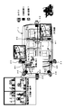
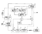
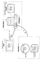
- FIG. 1 is a diagram showing a mounting example of an in-vehicle image data compression / decompression apparatus.
- a plurality of cameras 2-1 to 2-6 are provided outside the car 1, a plurality of monitors 3 and rear monitors 4-1 to 4-2 are provided in the car 1, and these are connected by an in-vehicle LAN 5.
- image data compression devices 6-1 to 6-6 are connected to the cameras 2-1 to 2-6, respectively, and image data restoration devices 7-1 to 7-7 are connected to the monitor 3 and the rear monitors 4-1 to 4-2.
- the image data of the images taken by the cameras 2-1 to 2-6 and the image data of the images by car navigation (not shown) are compressed by the image data compression devices 6-1 to 6-6, and are transmitted via the in-vehicle LAN 5.
- the transferred compressed data is decompressed by the image data restoration devices 7-1 to 7-3, and then displayed on the monitor 3 and the rear monitors 4-1 to 4-2.
- High image quality high image quality both when the original image is a natural image and when it is a CG (Computer Graphics) image
- CG images digital images represented by maps of car navigation systems
- Many digital components contain high frequency components.
- both digital images such as maps and natural images such as TV and movies have been handled.
- a data compression method effective for both low frequency components and high frequency components is desired.
- JPEG Joint Photographic Experts Group
- MPEG conversion coding
- DCT Discrete Cosine Transfer
- DCT conversion is a technique for frequency-converting image data. Since the human eye is sensitive to low-frequency components (flat parts in an image), the DCT coefficients related to low frequencies are fine, and the DCT coefficients related to high frequencies are roughly quantized, resulting in image quality degradation for natural images. It is possible to perform image compression at a high compression rate so as not to stand out.
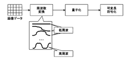
- FIG. 2 shows a method of encoding by DCT used for JPEG or the like which is a conventional technique.
- the original image data is first frequency converted and divided into a high frequency component and a low frequency component.
- the low frequency component is fine and the high frequency is roughly quantized, and the quantized component is encoded by a variable length code such as a Golomb code.
- a variable length code such as a Golomb code.
- JPEG can perform two-dimensional correlation by performing transform coding in units of 8 ⁇ 8 blocks, realizing a high compression rate (about 1/10).
- a high compression rate about 1/10
- at least 8 lines of memory are required, which increases the circuit scale.
- a considerable compression ratio (1/20 or more) can be expected to obtain a correlation between frames.
- the circuit scale is further increased. growing.
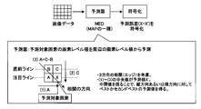
- JPEG-LS (Lossless) JPEG-LS is a compression method of still image data that can be reversibly compressed, taking into account the vertical and horizontal edges based on the MED (Media Edge Detector: MAP, DPCM) from the level values of surrounding pixels. A reasonable level value is predicted, and the prediction error is directly encoded.
- FIG. 3 shows a compression method using JPEG-LS, which is a conventional technique.
- JPEG-LS a pixel X is predicted from pixels A, B, and C in FIG. Then, an error (XX ′) between the predicted value X ′ and the actual measurement value X is obtained, and this is encoded to perform data compression.
- FIG. 1 Generate bit planes (black and white images of 0 and 1 at each bit depth, 8 planes if 8 bits).
- FIG. 6 for simplification, only a total of three planes are shown, that is, the plane obtained by the extrapolation process at the uppermost stage and the two planes obtained by the subsequent interpolation process.
- the pixels in each plane are hierarchically binary encoded.
- the encoding order and means are changed based on the state of surrounding pixels that have already been encoded.
- the simple average of the surrounding four pixels that have been restored is used as the pixel level value of the unrestored pixels.
- An object of the present invention is to provide an image compression apparatus / decompression apparatus, a compression method / decompression method, and a program that have high speed, low delay, high image quality, and a small circuit scale.
- the image compression apparatus includes a line memory unit, a dividing unit, a first predicted value calculating unit, a second predicted value calculating unit, and a predictive encoding unit.
- the line memory unit holds pixel values for at least one line immediately before the processing target line of the compression target image.
- the dividing unit divides the pixels of the processing target line into blocks each having 2 n pixels as one block.
- the first predicted value calculation unit performs processing in the line memory for the 2 n-1 and 2 n th pixels among the pixels in the block divided by the dividing unit as the first layer process.
- a prediction value is obtained by performing extrapolation prediction using the pixel value immediately above each of the 2 n ⁇ 1 and 2 n th pixels as a reference value.
- the second predicted value calculation unit performs processing from the second layer to the n-th layer, up to the pixel value of the immediately preceding line in the line memory and the previous layer of processing for a predetermined pixel.
- the prediction value is obtained by performing the interpolation prediction using the prediction value obtained in the above as a reference value.
- the prediction encoding unit obtains a prediction error from the prediction value obtained in the processes from the first layer process to the n-th layer process, converts the prediction error into a quantization number, and converts the quantization number into Convert to variable length code to obtain compression code.
- the memory only needs to have a line memory unit, so that the circuit scale can be reduced.
- the compression process can be performed at high speed.
- the image restoration device includes a line memory unit, a first predicted value calculation unit, a second predicted value calculation unit, and a restored pixel value calculation unit.
- the line memory unit holds pixel values for at least one line immediately before the processing target line of the restoration target image.
- the dividing unit divides the pixels of the processing target line into blocks each having 2 n pixels as one block.
- the first predicted value calculation unit performs processing in the line memory for the 2 n-1 and 2 n th pixels among the pixels in the block divided by the dividing unit as the first layer process.
- a prediction value is obtained by performing extrapolation prediction using the pixel value immediately above each of the 2 n ⁇ 1 and 2 n th pixels as a reference value.
- the second predicted value calculation unit performs processing from the second layer to the n-th layer, up to the pixel value of the immediately preceding line in the line memory and the previous layer of processing for a predetermined pixel.
- the prediction value is obtained by performing the interpolation prediction using the prediction value obtained in the above as a reference value.
- the restored pixel value calculation unit obtains a quantization number from the compression code, obtains a prediction error quantization value from the quantization number, and the prediction value obtained by the prediction error quantization value and the first prediction value calculation unit or The pixel value of the restored pixel is obtained using the prediction value obtained by the second prediction value calculation unit.
- the memory only needs to have a line memory unit, so that the circuit scale can be reduced.
- the restoration process can be performed at high speed.
- FIG. 19 It is a figure which shows the structural example of the image data decompression
- the image compression apparatus and the image restoration apparatus have a memory for about one line of an image in order to satisfy high image quality, low delay, light weight, and high-speed processing, and perform one block of MAP (Media Adaptive Predictor) prediction.
- MAP Media Adaptive Predictor
- MAP prediction is performed in consideration of interpolation prediction for high resolution component pixels.
- prediction methods there are extrapolation prediction that predicts the outer data from a certain data series and interpolation prediction that predicts the middle of a certain data series, but interpolation prediction grasps the tendency of the data series in advance. Because it is easy, the prediction accuracy is high.
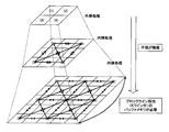
- FIG. 7 is a diagram illustrating an outline of a prediction method according to the present embodiment.
- image data is processed in 2 n units (hereinafter referred to as 1 block).
- the processing of the second layer the pixel X0 adjacent to the left of the pixel X1 (that is, X2 n in the previous block obtained by the processing for the previous block), the pixel X2 n ⁇ obtained by the processing of the first layer 1, and, by using the restored pixel value in the immediately preceding line, determined by just MAP predict an intermediate pixel in the order of pixels X2 n-2, X2 n- 1 + X2 n-2 of the pixel X2 n.
- the pixel X2 n-2 , X2 n-1 , X2 n-1 + X2 n-2 obtained up to the processing of the pixel X0 and the second level is used, and the pixel just in the middle of the pixel X2 n Are obtained by MAP prediction in the order of pixels X2 n-3 , X2 n-2 + X2 n-3 , X2 n-1 + X2 n-3 and X2 n-1 + X2 n-2 + X2 n-3 .
- the intermediate pixel of the pixels obtained so far is obtained by MAP prediction, and finally, as the processing of the nth layer, the intermediate pixels are MAP predicted in the order of pixels X1, X3,..., X2 n ⁇ 1. Ask for.
- the processing of the next layer can be started before the processing of a certain layer is completed, and the processing of two layers can be performed in parallel. I can do it.
- the pixel data required for processing is only the pixel data of the pixel immediately before the pixel to be processed and the pixel of the block to be processed, the pixel data corresponding to about one line of the image is held.
- the circuit of the image compression apparatus and the image restoration apparatus can be reduced to a small scale.
- the pixels X3 and X8 are predicted by extrapolation processing using the pixel data of the immediately preceding line 1 in the first layer processing.
- the pixels X2 and X6 are obtained by prediction by interpolation using the pixel data of the immediately preceding line 1 in the second layer processing and the pixel data obtained in the first layer processing.
- pixels X1, X3, X5, and X7 are obtained by prediction by interpolation processing using the pixel data of the immediately preceding line and the pixel data obtained by the processing of the first layer and the second layer by the processing of the third layer. .
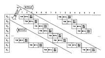
- FIG. 9 is a diagram more specifically showing the processing of each layer in FIG.
- the process is executed based on the pixel data for one line immediately before the processing line stored in the line memory and the pixel data obtained by prediction in the previous layer that has already been processed.
- the line memory stores a restored pixel of each pixel level value for the immediately preceding line.
- the processing order of 8 pixels in the target pixel block 3 is as follows (1), (2),..., (8).
- (1) corresponding to X4 in FIG. 8 is predicted and extrapolated from X′4 of the immediately preceding line 1 in the line memory as the first layer process.
- (2) corresponding to X8 of FIG. 8 is obtained by extrapolation from X′8 of the immediately preceding line 1 in the line memory.
- (3) corresponding to X2 in FIG. 8 is the processing of the pixels X′0, X′2, X′4 of the immediately preceding line 1 in the line memory and the processing of the first hierarchy of the processing line 1. It is obtained by MAP prediction from the pixels X0 and X4 obtained in the above.
- (4) corresponding to X6 in FIG. 8 is obtained from the pixels X′4, X′6, X′8 of the previous line 1 in the line memory and the processing of the first layer of the processing line 1. Obtained by MAP prediction from X4 and X8.
- (5) corresponding to X1 in FIG. 8 is the pixel X′0, X′1, X′2 of the immediately preceding line 1 in the line memory and the second hierarchy of the processing line 1. It calculates
- (6) corresponding to X3 in FIG. 8 is obtained by processing the pixels X′2, X′3, X′4 of the immediately preceding line 1 in the line memory and the processing of the first layer of the processing line 1, It calculates
- MAP performs high-performance prediction processing by using one of three prediction value candidates taking into account the correlation between the vertical direction and the horizontal direction as a prediction value.
- the pixels X4 and X8 can start processing the next block before completing the processing of all the pixels in the previous block only by using the pixel data value of the previous line. Become.
- the prediction process of the pixel X4 of the next block is started.
- the pixel data values of the pixels X2, X6, X1, X3, X5, and X7 are not used for the prediction process of the next block, they may be processed with a delay. For this reason, an extra processing time may be applied to the MAP accompanied by the interpolation processing capable of high-performance prediction.
- each processing is performed at a timing that does not overlap within the same clock so that only one prediction, quantization, and restoration pixel level value calculation circuit may be provided. It is also possible to provide a configuration that further shortens the processing period for each block by enabling processing with overlapping timing.
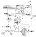
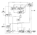
- FIG. 11 is a diagram illustrating a configuration example of the image data compression device 100 according to the present embodiment.
- image data 11 input to the image data compression apparatus 100 is a collection of pixels to be compressed, and pixel data is input in the line direction.
- the order control circuit 12a is a circuit that controls the processing order of the 8 pixels of the compression target block, and controls the pixel data output from the multiplexer in the image data compression apparatus 100 with a control signal.
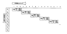
- a pixel processing timing by the image data compression apparatus 100 and the image data restoration apparatus 200 described later will be described with reference to FIG.
- the processing order of the pixels in one block is as shown in FIG. 10, with pixel X4 at the third clock, pixel X8 at the fourth clock, pixel X5 at the fifth clock, pixel X2 at the sixth clock, X6,8 at the seventh clock.
- the processing of the pixel X3 is completed at the clock, X7, the ninth clock at X1, and the tenth clock.
- the processing for the pixels X5 and X7 is processing for the pixels of the previous block because of timing.
- the multiplexer (MUX1) 13 is a multiplexer that sequentially distributes the pixels of the image data 11 input to the image data compression apparatus 100 pixel by pixel to the compression target pixel blocks in order to process in units of blocks.
- the compression target pixel block 14 holds pixel data (level value) of a pixel to be compressed in the current step.
- the pixels X5 and X7 also hold the pixel data of the previous block from the viewpoint of processing delay.
- the demultiplexer (DMUX1) 15 is a demultiplexer that passes the pixel level values in the compression target block 14 to the subsequent processing in the hierarchical order.
- the prediction line buffer 16 is a buffer that holds a restored pixel level value for at least one line immediately before the processing target block, and passes the value to the block line memory 17 immediately above the compression target block 14.
- the immediately above block line memory 17 is a line memory that holds a pixel level value of a line one pixel above the pixel in the compression target pixel block 14.
- the pixels X′ ⁇ 4, X′ ⁇ 3, X′ ⁇ 2, X′ ⁇ 1, and X′0 in the immediately above block line memory 17 are pixels X′4, X′5, and X′6 of the previous block. , X′7 and X′8.
- the compression target pixel block 18 is a buffer that holds a restored pixel level value that has been processed among the pixels of the compression target pixel block 004.
- the pixel level value in the compression target pixel block 18 is used for prediction value calculation.
- the pixels X-4, X-2, and X0 in the compression target pixel block 18 indicate the pixels X4, X6, and X8 of the previous block, and are used to process the pixels X5 and X7 of the previous block.
- the demultiplexer (DMUX2) 19 is a demultiplexer that outputs the level value of the pixel immediately above the compression target pixel to the predicted value calculation / selection module 26.
- the pixel immediately above corresponding to the prediction target pixel output from the demultiplexer 19 is as shown in FIG.
- the demultiplexer (DMUX 3) 20 is a demultiplexer that outputs a pixel level value used when calculating the binary average immediately above the compression target pixel to the binary average calculating module 24 immediately above.
- the binary average immediately above the prediction target pixel is as shown in B of FIG. 12, and the demultiplexer 20 outputs the pixel level value of the smaller number of the two pixels used for the average value calculation. Note that the demultiplexer 20 does not operate when the prediction target pixel is the pixel X4 or X8 processed in the first layer process.
- the demultiplexer (DMUX 4) 21 is a demultiplexer that outputs the pixel level value used when calculating the binary average immediately above the compression target pixel to the binary average calculating module 24.
- the binary average immediately above the prediction target pixel is as shown in FIG. 2B, and the demultiplexer 21 outputs the pixel level value of the larger number of the two pixels used for the average value calculation.
- the demultiplexer (DMUX4) 21 also does not operate when the pixel to be predicted is the pixels X4 and X8 processed by the first layer process.
- the demultiplexer (DMUX5) 22 is a demultiplexer that outputs the pixel level value of the pixel used when calculating the current line binary average of the compression target pixel to the current line binary average calculation module 25.
- the current line binary average corresponding to the prediction target pixel is as shown in FIG. 12A, and the demultiplexer 22 outputs the pixel with the smaller number of the two pixels used for the average value calculation.
- the pixel to be predicted is the pixel X4 or X8 processed in the first layer process, the pixel does not operate.
- the demultiplexer 23 (DMUX 6) is a demultiplexer that outputs to the current line binary average calculation module 25 the pixel level value used when calculating the binary average of the current line of the compression target pixel.
- the current line binary average corresponding to the prediction target pixel is as shown in FIG. 12A, and the demultiplexer 23 outputs the pixel level of the larger number of the two pixels used for the average value calculation. Further, the demultiplexer 23 does not operate when the prediction target pixel is the pixel X4 or X8 processed by the first layer process.
- the directly above binary average calculation module 24 is a module that calculates an average value of the binary values immediately above the compression target pixel.
- the current line binary average corresponding to the prediction target pixel is as shown in FIG.
- the immediately above binary average calculation module 24 does not operate when the pixel to be predicted is the pixels X4 and X8 processed by the processing of the first layer.
- the prediction method uses interpolation prediction in which the already restored pixel predicts with the prediction target pixel sandwiched between the prediction target pixel and the extrapolated prediction that predicts the outer pixel level value from the already restored pixel level value.
- the prediction accuracy is good. For this reason, if the reference value A on the previous line is also subjected to interpolation processing, the prediction accuracy can be further improved.
- the current line binary average calculation module 25 is a module that calculates the average value of the binary values of the compression target pixel and the pixels on both sides thereof.
- the current line binary average calculation module 25 does not operate when the prediction target pixel is the pixels X4 and X8 processed by the first layer process.
- the prediction method uses interpolation prediction in which the already restored pixel predicts with the prediction target pixel sandwiched between the prediction target pixel and the extrapolated prediction that predicts the outer pixel level value from the already restored pixel level value. But the prediction accuracy is good. For this reason, if the reference value A on the same line is also subjected to interpolation processing, the prediction accuracy can be further improved.
- the predicted value calculation / selection module 26 is a module that calculates and selects a predicted value according to a control signal from the sequence control circuit 12a based on the pixel immediately above the compression target pixel, the binary average above and the current line binary average.
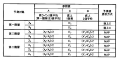
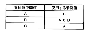
- FIG. 13 is a diagram showing a reference intermediate value and a predicted value corresponding to the reference intermediate value.
- the prediction value calculation by the prediction value calculation / selection module 26 uses only the pixel immediately above the compression target pixel in the processing of the first layer. However, in the processing subsequent to the processing of the second layer, the predicted value calculation / selection module 26 calculates the intermediate value of these values when the current line binary average is A, the immediately upper binary average is B, and the immediately upper pixel is C.
- the prediction value to be used is determined from A, C, and A + C ⁇ B so as to correspond to FIG.
- the predicted value 27 is a predicted value calculated by the predicted value calculation / selection module 26.
- the subtractor 28 is an arithmetic unit that calculates a prediction error by subtracting the prediction value 27 from the compression target pixel output from the demultiplexer (DMUX1) 15.
- the quantizer 29 quantizes a prediction error that is a difference value between a compression target pixel and a prediction value.
- the quantizer 29 receives the prediction error and outputs a quantization value and a quantization number.
- the prediction error, the prediction error quantization value, and the quantization number are associated as shown in FIG. Based on the table of FIG. 14, the quantizer 29 outputs a corresponding prediction error quantization value and quantization number from the input prediction error.
- the adder 30 is an arithmetic unit that adds the predicted value 27 and the prediction error quantized value output from the quantizer 29 to calculate a restored pixel level value and outputs it to the multiplexer (MUX2) 31 and the multiplexer (MUX3) 32. is there.
- the multiplexer (MUX2) 31 is a multiplexer that outputs the restored pixel level values X2, X4, X6, and X8 to the compression target pixel block 18.
- the multiplexer (MUX3) 32 is a multiplexer that sequentially outputs the restored pixel level value to the prediction line buffer 16.
- the variable length encoder 33 receives the quantization number output from the quantizer 29, converts it into a variable length code such as a Huffman code, and outputs it.
- the compression code buffer 34 is a buffer for accumulating the variable length code output from the variable length encoder 33.
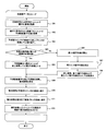
- FIG. 15 is a flowchart showing an operation process at the time of image data compression of the image data compression apparatus 100 of the present embodiment.
- step S1 the image data compression apparatus 100 compresses 8 pixels of the input image data 11 into pixels to be compressed. Store in block 14.
- step S2 the image data compression apparatus 100 transfers the pixels X′-4, X′-3, X′-2, X′-1, X′0, X ′ from the prediction line buffer 16 to the block line memory immediately above. 1, pixel level values corresponding to X′2, X′3, X′4, X′5, X′6, X′7, and X′8 are stored.
- step S3 the pixel level values of the pixels X4, X6, and X8 in the previous block are overwritten in the pixels X-4, X-2, and X0 in the compression target pixel block 14 based on the control signal from the sequence control circuit. To do.
- step S4 if the compression target pixel is the pixel X4 or X8 to be processed in the first layer (step S4, Yes), the processing in the first layer, that is, the predicted value calculation / selection module 26 is performed in step S5.
- the pixel level values of the pixels X′4 and X′8 immediately above the processing target pixels X4 and X8 output from the demultiplexer (DMUX2) 19 are output as the predicted value 27.
- step S4 if the compression target pixel is not the pixel X4 or X8 that is the processing target of the first layer (No in step S4), the pixel is the processing target pixel of the second layer or later, so that MAP prediction is performed.
- the immediately upper binary average value is calculated by the immediately upper binary average value calculation module 24 based on the values selected and output from the demultiplexer (DMUX3) 20 and demultiplexer (DMUX4) 21, and in step S7 the current line Based on the values selected and output from the demultiplexer (DMUX5) 22 and the demultiplexer (DMUX6) 23 by the binary average value calculation module 25, the current line binary average value is calculated.
- step S8 the predicted value 26 is calculated by using the predicted value calculation / selection module 26 using the pixel immediately above, the immediately upper binary average value obtained in steps S6 and S7, and the current line binary average value.
- step S9 the image data compression apparatus 100 subtracts the predicted value 27 from the pixel level value of the compression target pixel selected and output from the compression target pixel block 14 by the demultiplexer (DMUX1) by the subtractor 28, thereby obtaining a prediction error. Is calculated.
- step S10 the prediction error calculated in step S9 is quantized by the quantizer 29, and a prediction error quantization value and a quantization number are output.
- step S11 the image data compression apparatus 100 adds the prediction error quantization value and the prediction value 27 by the adder 30 to obtain a restored pixel, and outputs this to the multiplexer (MUX2) 31 and the multiplexer (MUX3) 32.
- step S12 Yes
- the restoration pixel of the pixels X2, X4, X6, and X8 is held in the compression target pixel block 18 by the multiplexer (MUX2) 31 as step S13.
- the process of step S13 is skipped. Then, the image data compression apparatus 100 passes the restored pixel to the prediction line buffer 16 through the multiplexer (MUX3) 32 in step S14.
- the image data compression apparatus 100 generates a code by the variable length encoder 33 based on the quantization number.
- the type of code used at this time may be a Golomb code or an arithmetic code.
- steps S1 to S15 are performed on the previous image data, and when the processing is completed for all the image data, this processing ends.
- the high resolution component second and third hierarchies
- FIG. 16 is a diagram illustrating a configuration example of the image data restoration device 200 in the present embodiment.
- the constituent elements for obtaining the predicted value 27 perform basically the same operations as the constituent elements of the image data compression apparatus 100 of FIG. 11, and these are denoted by the same reference numerals. It has been. Detailed descriptions of these components are omitted.
- a compression code 41 is obtained by encoding image data, and is data to be restored by the image data restoration device 200 of the present embodiment.
- the inverse encoder 42 receives a compression code 41 and outputs a quantization number corresponding to the compression code 41.
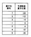
- the inverse quantizer 43 receives the quantization number output from the inverse encoder 42 and outputs a prediction error quantized value 44.
- the quantization number and the prediction error quantization value have a relationship as shown in FIG. 17 and, of course, are the same as the relationship between the prediction error quantization value and the quantization number shown in FIG.
- the inverse quantizer 43 outputs a prediction error quantization value 44 corresponding to the input quantization number.
- the prediction error quantization value 44 is a quantization value of the prediction error output from the inverse quantizer 43.
- the order control circuit 12b is a circuit that controls the processing order of the eight pixels of the restoration target block, and outputs a control signal to control the output of each multiplexer (MUX) and demultiplexer (DMUX).
- MUX multiplexer
- DMUX demultiplexer
- the pixel processing order is the pixels X4, X8, X5, X2, X6, X7, X1, and X3, as shown in FIG. However, due to timing, the pixels X5 and X7 are processed for the pixels of the previous block.
- the adder 45 adds the predicted value 27 and the predicted error quantization value 45 to calculate a restored pixel level value.
- the multiplexer (MUX1) 46 is a multiplexer that sequentially distributes the restored pixels one by one to the restored pixel block 47.
- the restoration completion pixel block 47 holds a pixel level value that has been restored by the restoration process currently being performed.
- the demultiplexer (DMUX1) 48 is a demultiplexer that rearranges and outputs the pixel data in the restoration completion pixel block 47 in the order before compression (X1, X2, X3, X4, X5, X6, X7, X8).
- the restored image data 49 is image data as a result of restoration by the image data restoration device 200.
- FIG. 18 is a flowchart showing an operation process during the decompression process of the compressed data of the image data decompression apparatus 200 in the present embodiment.
- step S21 when the compression code 41 is input to the image data restoration apparatus 200 and the processing is started, first, in step S21, the inverse encoder 42 obtains a quantization number based on the input compression code 41.
- step S22 the image data restoration apparatus 200 obtains a prediction error quantization value 44 by the inverse quantizer 43 based on the quantization number obtained in step S21.
- step S23 the pixels X′-4, X′-3, X′-2, X′-1, X′0, X′1, X ′, which are output from the prediction line buffer 16 to the block line memory 17 immediately above.
- the pixel level values corresponding to '2, X'3, X'4, X'5, X'6, X'7, and X'8 are held.
- step S24 in the compression target pixel block 18, the values of the pixels X4, X6, and X8 of the previous block are overwritten on X-4, X-2, and X0 based on the control signal from the sequence control circuit 12b.
- the image data restoration device 200 determines whether or not the pixel to be restored is X4 or X8 in step S25, and if it is these pixels (step S25, Yes), the prediction is performed as the process in step S26.
- the value calculation / selection module 26 outputs the pixel level value of the pixel immediately above output from the demultiplexer (DMUX 2) 19 as the predicted value 27 of the pixel level value of the pixel immediately above the compression target pixel.
- step S25 the binary average calculation module 24 selects the demultiplex (DMUX3) 20 and demultiplex (DMUX4) 21 as step S27.
- the average value immediately above the selection is calculated from the output value and is output to the predicted value calculation / selection module 26.
- step S28 the current line binary average value calculation module 25 calculates a reference value from the values selected and output by the demultiplex (DMUX5) 22 and the demultiplex (DMUX6) 33, and the predicted value calculation / selection module 26 receives the reference value. Output.
- step S29 the predicted value calculation / selection module 26 calculates the predicted value 27 based on FIGS. 12 and 13 based on the binary average value directly obtained in step S27 and the current line binary average value obtained in step S28. Ask.
- the image data restoration device 200 calculates the restored pixel by adding the predicted error quantization value 44 obtained in step S22 and the predicted value 27 by the adder 45 as step S30. To do.
- step S30 If the restoration pixel calculated in step S30 is the restoration pixel of the pixels X2, X4, X6, and X8 (step S31, Yes), it is input to the restoration target pixel block 18 by the multiplexer (MUX2) 31 as step S31. If it is a restored pixel of any other pixel (step S31, No), step S31 is skipped.
- MUX2 multiplexer
- the restored pixel is input to the prediction line buffer 16 by the multiplexer (MUX 3) 32.
- the image data restoration device 200 inputs all restoration pixels to the restoration completion block 47 as step S34.
- the restored pixels in the restored block 47 are output in the order before compression (X1, X2, X3, X4, X5, X6, X7, X8) by the demultiplexer (DMUX1) 48. To do.
- step S21 to S35 is repeated for all the image data, and when the restoration processing is completed for all the image data, this processing is terminated.
- the pixels in the line are divided into blocks, and the processing timing is shifted in units of hierarchies within the block. The upper bottleneck can be eliminated.
- the intermediate value calculation is performed by referring to and interpolating the restored values of the previous line and the previous hierarchy, high-precision prediction is possible.
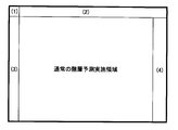
- FIG. 19 is a diagram illustrating a position in one frame of image data on which exception processing is performed in the image data compression processing and decompression processing in the present embodiment.
- 0x80 is 80 in hexadecimal notation and 128 in decimal notation. This 128 is half the value when the number of gradations of the pixel is 256 gradations.
- the pixel at the position (1) in FIG. 19 there is no pixel immediately before the extrapolation process when performing the first layer process, so that the extrapolation process is performed assuming that there is a pixel of this 128 value (0x80).
- the value of the corresponding pixel of the previous block is used as the predicted value.
- a pixel having a gradation number of 0x80 (this is 128 in decimal notation and half the value when the gradation number is 256) at the position of the original portion.
- Interpolation processing is performed on the assumption that it exists, and a predicted value is obtained.
- FIG. 21 shows an example of an alternative pixel when the predicted value of the pixel at the leftmost position (3) in FIG. 19 is obtained.
- the pixel X of the pixel 52 immediately above it is obtained.
- the value of the pixel X′1 is used as a substitute pixel at the position of “0” and the position of the pixel X0 on the processing line 53.
- the reference value is configured by using the substitute pixels at the positions X′9 and X9.
- the image data compression processing and decompression processing according to the present embodiment can cope with the end of the frame of the image data.
- FIG. 22 is a diagram showing a program configuration example of the data compression program 300 in the present embodiment.
- the constituent units of the data compression program 300 in the figure are realized by the CPU executing the data compression program 300 on the memory.
- the data compression program 300 may be configured as a single program or a program group including a plurality of programs.
- image data 61 is pixel data (gradation values) to be subjected to data compression by the data compression program 300 of this embodiment.
- the pixel data 61 is input to the data compression program 300 in the line direction.
- the image format 62 is information indicating the horizontal image size of the image data 61 and is input to the data compression program 300 when data compression processing is performed.
- the layer-by-layer access unit 63 is a program unit that classifies each pixel based on the horizontal pixel size of the frame of the image and accesses each pixel data so as to execute encoding processing by layer.
- N When the hierarchy is N, it is classified as follows. In the present embodiment, unlike the case where the compression processing is performed by the hardware described above, the processing may be performed in parallel or not. Therefore, how to divide the blocks and how to select the pixels in each layer have been described so far. Unlike the following. ⁇ Number of pixels in each block: 2 N-1 (one block is half the size) First layer: One pixel exists for each block, and the pixel at the right end of the block is selected. Second layer: One pixel exists for each block, and the 2 N- 2th pixel from the left end is selected. I-th layer: 2 i ⁇ 2 pixels exist for each block, selected from the 2 Ni- th pixel from the left end, and selected every 2 N ⁇ i + 1 pixels toward the right end. Nth layer: 2 N ⁇ 2 exist for each block, selected from the first pixel from the left end, and selected every second block toward the right end.
- the compression target line memory area 64 is a memory area that holds the level value of the pixel of the line to be compressed in the current step, and is provided on the memory area of the information processing apparatus by the data compression program 300.
- the prediction line memory area 66 is a memory area that holds the restored pixel level value of the line immediately before the processing line, and is provided on the memory area of the information processing apparatus by the data compression program 300.
- the directly upper binary average calculating unit 68 is a program unit for calculating an average value of binary values immediately above the compression target pixel. This calculation is also performed in the second and subsequent layers, and the calculation method is as follows.
- the predicted value calculation / selection unit 69 is a program unit that calculates and selects a predicted value based on the pixel immediately above, the binary average immediately above, and the current line binary average.
- the first layer uses only the pixels immediately above, but the second and subsequent layers calculate the intermediate value when the current line binary average is A, the immediately upper binary average is B, and the immediately upper pixel is C, A predicted value to be used is determined from A, C, and A + CB so as to correspond to FIG.
- the subtraction unit 65 is a program unit that subtracts the prediction value calculated by the prediction value calculation / selection unit 69 from the pixel level value of the compression target pixel read from the compression target line memory area 64 and calculates a prediction error.
- the quantization unit 71 is a program unit that quantizes a “prediction error” that is a difference value between a compression target pixel and a predicted value.
- the quantization unit 71 receives the prediction error and outputs a prediction error quantization value and a quantization number.
- the relationship between the prediction error, the prediction error quantization value, and the quantization number is as shown in FIG.
- the variable length encoding unit 72 is a program unit that receives a quantization number and outputs a variable length code.
- the compression code memory area 73 is a buffer for accumulating the variable length code output from the variable length coding unit 72 as a compression code.
- the compression code memory area 73 is secured by the data compression program 300 on the memory of the information processing apparatus on which the data compression program 300 is executed.
- FIG. 23 is a flowchart showing an operation process of the data compression program 300 when compressing image data. The processing in the figure is realized by the CPU of the information processing apparatus executing the data compression program 300 on the memory.
- step S41 When the process shown in FIG. 6 starts, first, one line of the image data 61 is stored in the compression target line memory area 64 in step S41. Next, in step S42, the compression target pixels for one block are classified from the first layer processing to the Nth layer processing target pixels.
- step S43 the predicted value calculation / selection unit 69 reads from the prediction line memory area 66. If the current process is the process of the first layer (step S44, Yes), as the process of the first layer, the predicted value calculation / selection unit 69 performs the pixel level value of the pixel immediately above the compression target pixel in step S45. Is a predicted value.
- step S44 if the current process is a process after the second hierarchy (No in step S44), the immediately upper two average calculating unit 68 calculates the immediately upper binary average value in step S46, and the current line in step S47.
- the binary average value calculation unit 67 calculates the current line binary average value, and uses the immediately upper binary average value calculated in step S46 in step S49 and the current line binary average value calculated in step S47 to calculate the compression target pixel. Find the predicted value.
- step S49 the subtracting unit 65 subtracts the predicted value from the pixel level value of the compression target pixel to calculate a prediction error.
- step S50 the prediction error obtained in step S49 is quantized by the quantization unit p71 to obtain a quantization value and a quantization number.
- step S51 the restored pixel is calculated by adding the quantized value obtained in step S50 by the adding unit 70 and the predicted value obtained in steps S45 and S48.
- step S52 the restored pixel is stored in the prediction line memory area 66.
- step S 53 the variable length coding unit 72 converts it into a variable length code, generates a compressed code, and stores it in the compressed code memory area 73.
- This compression code may be a Golomb code or an arithmetic code.
- step S43 to S53 is first performed on the first layer processing of all the blocks in one line, and then the processing is performed in order of each layer. Then, the processing from step S41 to S53 is performed on all the image data, and when the compression code is generated, this processing is terminated.
- the image data of this embodiment can be compressed by software, not hardware.
- exception processing is performed.
- FIG. 24A is a diagram showing calculation of a predicted value in the case of the position (3) in FIG.
- the predicted value of each block 83 is obtained on the assumption that a pixel having a pixel level value of the left end terminal pixel of the previous line 81 exists at the left ends of the previous line 81 and the current line 82.
- FIG. 24B is a diagram illustrating calculation of a predicted value in the case of the position (4) in FIG.
- each block 83 is assumed to have pixels of the pixel level value of the rightmost pixel of the previous block at that position by the number of pixels that are insufficient for the rightmost block of the previous line 81 and the current line 82. Find the predicted value of.
- FIG. 25 is a diagram showing a program configuration example of the data restoration program 400 in the present embodiment.
- the constituent units of the data restoration program 400 in the figure are realized by the CPU executing the data compression program 300 on the memory.
- the data restoration program 400 may be configured as a single program or a program group including a plurality of programs.
- the constituent elements for obtaining the predicted value perform basically the same operations as the constituent elements of the image data compression program 300 of FIG. 22, and these are denoted by the same reference numerals. It has been. Detailed descriptions of these components are omitted.
- a compression code 91 is obtained by encoding image data, and is data to be restored by the image data restoration program 400 of the present embodiment.
- the inverse encoding unit 92 is a program unit that converts the compression code 91 into a corresponding quantization number.
- the inverse quantization unit 93 converts the quantization number converted by the inverse encoding unit 93 into a prediction error quantization value. As described above, the quantization number and the prediction error quantization value have a relationship as shown in FIG. 17, and the inverse quantization unit 93 converts the quantization number into a corresponding prediction error quantization value.
- the addition unit 94 is a program unit that obtains a restored pixel by adding the prediction error quantized value and the predicted value.
- the restoration completion pixel block area 95 is a memory area for storing the pixel level value of restoration pixels for one block, and is secured by the data restoration program 400 on the memory of the information processing apparatus on which the data restoration program 400 is executed.
- the order conversion unit 96 is a program unit that reads pixel level values from the restoration complete pixel block area 95 in the order before compression.
- FIG. 26 is a flowchart showing an operation process of the data restoration program 400 when restoring image data.
- the processing shown in the figure is realized by the CPU of the information processing apparatus executing the data restoration program 400 on the memory.
- step S61 the compression code 91 is converted into a quantization number by the inverse encoding unit 92 in step S61.
- step S62 a prediction error quantization value is acquired by the inverse quantization unit 93 based on the quantization number obtained in step S61.
- step S63 the prediction value calculation / selection unit 69 reads the pixel level value of the block immediately above the restoration target block from the prediction value line memory area. If the current pixel to be processed is a pixel to be processed in the first hierarchy (step S64, Yes), the predicted value calculation / selection unit 69 determines the pixel level value of the pixel immediately above the pixel to be processed as step S65. Is output as a predicted value.
- the immediately upper two average calculating unit 68 calculates the immediately upper binary average value in step S65.
- the current line binary average value calculation unit 67 calculates the current line binary average value, and in step S68, uses the immediately upper binary average value calculated in step S66 and the current line binary average value calculated in step S67. The predicted value of the compression target pixel is obtained.
- step S65 or step S68 When the predicted value is obtained in step S65 or step S68, the pixel level value of the compression target pixel and the predicted value are added by the adding unit 94 in step S69 to calculate a restored pixel.
- step S70 the restored pixel calculated in step S69 is stored in the prediction line buffer memory area 65, and in step S71, the restored pixel is saved in the restoration completed pixel block area 95.
- the order conversion unit 96 reads out and outputs the pixel level values of the restored pixels from the restored pixel block area 95 in the order of the image data before compression. This output becomes restored image data.
- the restoration process by the data restoration program 400 is completed by repeating the above steps S61 to S72 for all the compressed image data.
- the image data restoration method of the present embodiment can also be realized by a software method by executing the data restoration program 400.
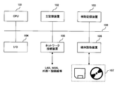
- FIG. 27 is a diagram illustrating a system environment of an information processing apparatus in which the data compression program 300 and the data restoration program 400 are executed.
- an information processing apparatus includes a CPU 101, a main storage device 102 such as a RAM, an auxiliary storage device 103 such as a hard disk, an input / output device (I / O) 104 such as a display, a keyboard, and a pointing device, a communication interface, a modem, and the like.
- a network connection device 105 and a medium reading device 106 that reads out stored contents from a portable storage medium such as a disk or a magnetic tape are provided, and these are connected to each other via a bus 108. Each component exchanges data with each other via the bus 108.
- the CPU 101 executes a program on the auxiliary storage device 103 or a program installed via the network connection device 105 by using the main storage device 102 as a work memory, so that the data compression program 300 and the data shown in FIGS.
- the function of each component of the restoration program 400 is realized, and the processing of the flowcharts shown in FIGS. 23 and 26 is realized.
- the program and data stored in the storage medium 108 such as magnetic tape, flexible disk, CD-ROM, MO, and DVD are read out by the medium reading device 107, and this is read by the external interface 106.
- the programs and data are stored in the main storage device 102 and the auxiliary storage device 103, and executed or used by the CPU 101, thereby realizing the processing of the flowchart described above in software.
- application software may be exchanged using a storage medium 107 such as a CD-ROM. Therefore, the present invention is not limited to an image data compression device, a decompression device, a compression method, a decompression method, and a program, and a computer for causing a computer to perform the functions of the above-described embodiments of the present invention when used by a computer. It can also be configured as a readable storage medium 107 or a program.
- the “storage medium” includes, for example, a medium drive device 117 such as a CD-ROM, a flexible disk (or an MO, DVD, memory card, removable hard disk, etc.) as shown in FIG.
- Removable portable storage medium 116, storage unit (database or the like) 112 in an external device (server or the like) transmitted via the network line 113, or memory (RAM or hard disk) in the main body 114 of the information processing device 111 Etc.) 115 etc. are included.
- the program stored in the portable storage medium 116 or the storage unit (database or the like) 112 is loaded into a memory (RAM or hard disk or the like) 115 in the main body 114 and executed.
- blue colors such as Blu-ray Disc (registered trademark) and AOD (Advanced Optical Disc) are also exemplified.
- the present invention can also be implemented using various types of large-capacity storage media that will be developed in the future, such as next-generation optical disk storage media using lasers, HD-DVD9 using red lasers, Blue Laser DVDs using blue-violet lasers, and holograms. Is possible.
- the pixel in the line is divided into blocks, and the processing timing bottleneck due to the prediction processing can be eliminated by shifting the processing timing in units of layers within the block.
Landscapes
- Engineering & Computer Science (AREA)
- Multimedia (AREA)
- Signal Processing (AREA)
- Compression Or Coding Systems Of Tv Signals (AREA)
- Compression Of Band Width Or Redundancy In Fax (AREA)
Abstract
Description
図1は、車載用の画像データ圧縮/復元装置の搭載例を示す図である。
(1)高画質であること(原画像が自然画のときとCG(Computer Graphics)画像のときの双方において高画質であること)
車載で扱う画像情報としては、一般テレビ画像や映画等に代表される自然画と、カーナビの地図等に代表されるCG画像(デジタル画像)が知られており、一般的に自然画では低周波成分が、またデジタル画像では高周波成分が多く含まれている。最近の車載端末や携帯電話を含む携帯端末では、地図などのデジタル画像と、TVや映画などの自然画像との両方を扱うようになってきており、両方の画像データを効率的に伝送するためには、低周波成分と高周波成分の両方に効果的なデータ圧縮方式が望まれている。
(2)低遅延であること(圧縮、復元に時間がかからない、車載カメラ向け)
車載で扱う画像情報としては、周辺監視カメラからの映像がある。リアルタイム監視のためには、圧縮及び復元処理に時間がかからず低遅延であることが求められる。
(3)装置が軽量であること(回路規模小)
映像情報の伝送は通常車載LANによって行われるが、多重伝送となるとLAN端末毎に圧縮、復元装置が必要になるため、個々の回路規模が小さいことが必要となる。
(4)高速処理が可能なこと
動画像の場合は、1秒間に30~60フレーム程度の画像データが送受信されるため、単位時間当たりで高速にデータ圧縮が可能であること必要となる。特に、近年はハイビジョン映像など高解像度化が進んでおり、更に高速にデータ圧縮を行う必要がある。
(1) JPEG、MPEG(変換符号化)
JPEG、MPEGでは、原画像に対してDCT(Discrete Cosine Transfer)変換を行い、得られたDCT係数に対して量子化を行う。
図2に従来技術であるJPEG等に用いられるDCTによる符号化の仕方を示す。
(2) JPEG-LS(Lossless)
JPEG-LSは、可逆圧縮が可能な静止画像データの圧縮方式で、周辺画素のレベル値からMED(Median Edge Detector:MAP、DPCMの一種)を元に縦方向と横方向のエッジを考慮して妥当なレベル値を予測し、その予測誤差を直接符号化する。
JPEG-LSでは、原画像データを予測器によって図3の画素A、B、Cから画素Xを予測する。そして予測値X’と実測値Xとの誤差(X-X’)を求め、これを符号化することによりデータ圧縮を行う。
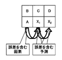
課題(1): 画質の調整が困難
JPEG-LSはロスレス圧縮であるので、ロッシー圧縮時に徐々に画質を落とすことが難しい。
例えば図4において、画素Aのデータが誤差を含んでいた場合、その誤差は画素X1 、画素X2 と伝播する。よって量子化ステップが荒いほど、予測精度が悪くなってしまう。
課題(2): 動画のリアルタイム圧縮復元が極めて困難
ロッシー圧縮では、ライン方向に一画素ずつ予測、量子化、復元画素レベル値の算出を実行するが、JPEG-LSによる圧縮では、次の画素を予測するのに直前の画素の復元画素レベル値が必要となる。よって高速処理が難しい。
(3) 階層符号化あるいは順次再生符号化方式(特許文献1、特許文献2)
予測符号化方式を高画質化、高圧縮化(画質調整)するには、階層的に予測を用いる方法がよく採られる。以下に従来技術による階層予測の例を図6を用いて説明する。
1)ビットプレーン(各ビット深度での0と1の白黒画像、8bitならば8つのプレーン)を生成する。なお図6では、簡略化のために最上段の外挿処理によって求めたプレーンと、それに続く内挿処理によって求めた2つのプレーンの、計3つのプレーンのみを示している。
2)各プレーン中の画素を階層的に2値符号化する。第2階層以降は既に符号化されている周囲画素の状態を元に符号化順番、手段を変更する。
3)場合によっては全画素を符号化・復元せずに、既に復元した周囲4画素の単純平均を未復元画素の画素レベル値とする。
本画像圧縮装置は、ラインメモリ部、分割部、第1の予測値算出部、第2の予測値算出部及び予測符号化部を備える。
分割部は、前記処理対象ラインの画素を2n 画素を1ブロックとするブロック単位に分割する。
また各階層処理を並列に実行できるので、高速に圧縮処理を行なうことが出来る。
ラインメモリ部は、復元対象画像の処理対象ラインの少なくとも直前1ライン分の画素値を保持する。
第1の予測値算出部は、第1階層の処理として、前記分割部により分割したブロック内の各画素のうち、2n-1 番目と2n 番目の画素に対して、前記ラインメモリ内の該2n-1番目と2n 番目の画素それぞれの直上の画素値を参照値として外挿予測を行って予測値を求める。
また各階層処理を並列に実行できるので、高速に復元処理を行なうことが出来る。
本実施形態の画像圧縮装置及び画像復元装置は、高画質、低遅延、軽量、高速処理を満たすために、画像の約1ライン分のメモリを有し、MAP(Median Adaptive Predictor)予測を1ブロック内で階層的に交互に実行することで予測処理における処理速度上のボトルネックを解消する。
本実施形態の画像圧縮装置及び画像復元装置では、画像データを2n 単位(以下これを1ブロックという)で処理する。
本実施形態では、第一階層の処理として、まずX1からX2n の画素の内、ちょうど中間の画素X2n-1 と一番最後のX2n を隣接するすなわち直上の画素であるX’2n-1 とX’2n を用いて外挿処理で求める。
図8は、n=3とした場合の本実施形態の処理を示す図である。
n=3なので処理を三階層に分類し、第一、第二、第三階層の順番で予測符号化を実行する。
図9は、図8の各階層の処理をより具体的に示した図である。
ラインメモリには直前ライン1分の各画素レベル値の復元画素が格納されている。
まず第1階層の処理として図8のX4に該当する(1)をラインメモリ内の直前ライン1のX’4から外挿処理により予測して求める。次に図8のX8に該当する(2)をラインメモリ内の直前ライン1のX’8から外挿処理により予測して求める。
図8のX5に該当する(7)をラインメモリ内の直前ライン1の画素X’4、X’5、X’6及び処理ライン1の第2階層の処理までに求まっている画素X4、X6からMAP予測により求め、また図8のX7に該当する(8)をラインメモリ内の直前ライン1の画素X’6、X’7、X’8及び処理ライン1の第2階層の処理までに求まっている画素X6、X8からMAP予測により求める。
通常MAPは縦方向と横方向の相関を考慮した3つの予測値候補の中から1つを予測値とすることで高性能な予測処理を行うが、本実施形態においても、第2階層以降は前階層の復元画素を参照することで、縦方向と横方向の相関を考慮した3つの予測値候補を算出することが可能である。このため、更に予測精度を高めることが可能となり高画質の圧縮を行なうことが出来る。
同図においてまず画素X4及びX8は、1つ前のラインの画素データ値を使用するだけで、前のブロック中の全画素の処理を完了する前に次のブロックの処理を始めることが可能になる。同図では、前のブロックの画素X6までが復元された時点で、次のブロックの画素X4の予測処理が開始されている。
図11は、本実施形態における画像データ圧縮装置100の構成例を示す図である。
同図の画像データ圧縮装置100は、上述したように連続して入力される画像データ11を8画素(n=3)毎に処理する構成を示している。
1ブロック内の画素の処理順番は図10のとおりで、3クロック目で画素X4、4クロック目で画素X8、5クロック目で画素X5、6クロック目で画素X2、7クロック目でX6、8クロック目でX7、9クロック目でX1、10クロック目で画素X3の処理を完了している。ただし、タイミングの関係上、画素X5、X7に対する処理は、前のブロックの画素に対しての処理となる。
マルチプレクサ(MUX3)32は、復元画素レベル値を予測用ラインバッファ16に順次出力するマルチプレクサである。
圧縮符号バッファ34は、可変長符号化器33から出力される可変長符号を蓄積するバッファである。
図15は、本実施形態の画像データ圧縮装置100の画像データ圧縮時の動作処理を示すフローチャートである。
このように本実施形態の画像データ圧縮装置100による画像圧縮では、ライン内の画素を2n (上記例ではn=3)毎のブロックに分け、ブロック内で階層単位に処理タイミングをずらすことで、予測処理による処理速度上のボトルネックを解消する。また、高解像度成分(第二、三階層)については、前ライン及び前階層の復元値を参照、内挿する中間値算出を実行するため、高精度な予測が可能となる。
図16は、本実施形態における画像データ復元装置200の構成例を示す図である。
なお同図の構成要素において、予測値27を求める部分の構成要素は図11の画像データ圧縮装置100の構成要素と基本的に同じ動作を行うものであり、これらについては、同一の符号が付せられている。そしてこれらの構成要素については、詳細な説明は省略する。
図18は、本実施形態における画像データ復元装置200の圧縮データの復元処理時の動作処理を示すフローチャートである。
そしてステップS23において、直上ブロックラインメモリ17に予測用ラインバッファ16から出力される画素X’-4、X’-3、X’-2、X’-1、X’0、X’1、X’2、X’3、X’4、X’5、X’6、X’7、X’8に該当する画素レベル値を保持する。またステップS24として、圧縮対象画素ブロック18において、順序制御回路12bからの制御信号に基づいて前ブロックの画素X4、X6、X8の値をX-4、X-2、X0に上書きする。
そして次に画像データ復元装置200は、ステップS34として全ての復元画素を復元完了ブロック47に入力する。そしてステップS35として復元画素を復元完了ブロック47内の復元画素をデマルチプレクサ(DMUX1)48によって圧縮前の順番(X1、X2、X3、X4、X5、X6、X7、X8)にして復元画素を出力する。
以上のように本実施形態における画像データ復元装置200による復元処理では、上記のように、ライン内の画素をブロックに分け、ブロック内で階層単位に処理タイミングをずらすことで、予測処理による処理速度上のボトルネックを解消することができる。また、高解像度成分(第二、三階層)については、前ライン及び前階層の復元値を参照、内挿する中間値算出を実行するため、高精度な予測が可能となる。
図19は、本実施形態における画像データ圧縮処理及び復元処理で例外処理を行なう画像データの1フレーム中の位置を示す図である。
画像データの1ライン目にあたる(1)と(2)は、直上のローカルデコード値が存在しないため、参照値A~CのMedianを取るのではなく図21に挙げた値を予測値とする。
図19の(1)の位置の画素では、第1階層の処理を行なうにあたって、外挿処理を行なうための直前の画素が無いのでこの128の値(0x80)の画素があるものとして外挿処理を行なって予測値を求める。また図19の(2)では、前ブロックの対応画素の値を予測値として用いる。
図21は、図19の左端の(3)の位置の画素の予測値を求めるときの、代替画素の例を示すもので、注目画素ブロック51の予測値を求める際に直上画素52の画素X’0の位置と処理ライン53の画素X0の位置に画素X’1の値を代替画素として用いている。
このように本実施形態における画像データ圧縮処理及び復元処理では、画像データのフレームの端に対しても対応することが出来る。
図22は本実施形態におけるデータ圧縮プログラム300のプログラム構成例を示す図である。同図中のデータ圧縮プログラム300の構成ユニットは、CPUがメモリ上のデータ圧縮プログラム300を実行することによって実現される。
同図において、画像データ61は、本実施形態のデータ圧縮プログラム300によるデータ圧縮の対象となる画素のデータ(階調値)である。この画素データ61はデータ圧縮プログラム300にライン方向に入力される。画像フォーマット62は、画像データ61の横画像サイズを示す情報で、データ圧縮処理が行われる際に、データ圧縮プログラム300に入力される。
・各ブロック内の画素数:2N-1 個(1ブロックの大きさはこれまでの半分)
・第1階層:各ブロックあたり1個存在し、ブロック右端の画素が選択される。
・第2階層:各ブロックあたり1個存在し、左端から2N-2 番目の画素が選択される。
・第i階層:各ブロックあたり2i-2 個存在し、左端から2N-i 番目の画素から選択され、右端へ向けて2N-i+1 個おきに選択される。
・第N階層:各ブロックあたり2N-2 個存在し、左端から1番目の画素から選択され、右端へ向けて2個おきに選択される。
第i階層、画素Xjの現ライン2値平均“C”: (Xk+Xl)/2 ※,k=j+2N-2 ,l=j-2N-2
となる。
予測値算出・選択ユニット69は、直上画素、直上2値平均および現ライン2値平均をもとに、予測値を算出、選択するプログラムユニットである。第一階層目は直上画素しか使用しないが,第二階層以降は現ライン2値平均をA、直上2値平均をB、直上画素をCとした場合に,これらの中間値を算出して、図12に対応するようにA,C,A+C-Bの中から使用する予測値を決定する。
第i階層,画素Xjの直上画素“A”:X’j
第i階層,画素Xjの直上ライン2値平均“B”:(X’k+X’l)/2 ※,k=j+2N-2 ,l=j-2N-2
第i階層,画素Xjの現ライン2値平均“C”:(Xk+Xl)/2 ※,k=j+2N-2 ,l=j-2N-2
減算ユニット65は、圧縮対象ライン用メモリ領域64から読み出した圧縮対象画素の画素レベル値から予測値算出・選択ユニット69が算出した予測値を減算して予測誤差を算出するプログラムユニットである。
圧縮符号メモリ領域73は、可変長符号化ユニット72から出力される可変長符号を圧縮符号として蓄積するバッファである。この圧縮符号メモリ領域73は、データ圧縮プログラム300によって、データ圧縮プログラム300が実行される情報処理装置のメモリ上に確保される。
図23は、画像データを圧縮する際のデータ圧縮プログラム300の動作処理を示すフローチャートである。同図の処理は情報処理装置のCPUがメモリ上のデータ圧縮プログラム300を実行することによって実現される。
次にステップS42として1ブロック分の圧縮対象画素を、第1階層の処理から第N階層の処理の対象画素に分類する。
そして現在の処理が第1階層の処理であったなら(ステップS44、Yes)、第1階層の処理として、ステップS45において予測値算出・選択ユニット69が圧縮対象画素の直上の画素の画素レベル値を予測値とする。
そしてステップS41からS53までの処理を全ての画像データに対して行ない、圧縮符号が生成されたなら、本処理を終了する。
なお図23の処理において、圧縮処理の対象画素が図19の(1)、(2)、(3)、(4)部分に該当する場合には、例外処理を行なう。
この場合、前ライン81と現ライン82の左端に更に前ライン81の左端終端画素の画素レベル値を持つ画素が存在するものとして各ブロック83の予測値を求める。
この場合、前ライン81と現ライン82の右端の1ブロックに不足する分の画素数分、その位置に1つ前のブロックの右端の画素の画素レベル値の画素が存在するものとして各ブロック83の予測値を求める。
図25は本実施形態におけるデータ復元プログラム400のプログラム構成例を示す図である。同図中のデータ復元プログラム400の構成ユニットは、CPUがメモリ上のデータ圧縮プログラム300を実行することによって実現される。
なお同図の構成要素において、予測値を求める部分の構成要素は図22の画像データ圧縮プログラム300の構成要素と基本的に同じ動作を行うものであり、これらについては、同一の符号が付せられている。そしてこれらの構成要素については、詳細な説明は省略する。
図26は、画像データを復元する際のデータ復元プログラム400の動作処理を示すフローチャートである。同図の処理は情報処理装置のCPUがメモリ上のデータ復元プログラム400を実行することによって実現される。
次にステップS62として、ステップS61で求めた量子化番号を元に逆量子化ユニット93によって予測誤差量子化値を取得する。
そして現在の処理対象の画素が第1の階層の処理対象の画素であったなら(ステップS64、Yes)、ステップS65として予測値算出・選択ユニット69は、処理対象画素の直上画素の画素レベル値を予測値として出力する。
このように本実施形態の画像データ復元方法は、データ復元プログラム400を実行することによるソフトウエア的手法によっても実現できる。
同図において情報処理装置は、CPU101、RAM等の主記憶装置102、ハードディスク等の補助記憶装置103、ディスプレイ、キーボード、ポインティングデバイス等の入出力装置(I/O)104、通信インタフェースやモデム等のネットワーク接続装置105、及びディスク、磁気テープなどの可搬記憶媒体から記憶内容を読み出す媒体読み取り装置106を有し、これらが互いにバス108により接続される構成を備えている。そして各構成要素は、バス108を介して互いにデータのやり取りを行う。
Claims (19)
- 圧縮対象画像の処理対象ラインの少なくとも直前1ライン分の画素値を保持するラインメモリ部と、
前記処理対象ラインの画素を2n 画素を1ブロックとするブロック単位に分割する分割部と、
第1階層の処理として、前記分割部により分割したブロック内の各画素のうち、2n-1 番目と2n 番目の画素に対して、前記ラインメモリ内の該2n-1 番目と2n番目の画素それぞれの直上の画素値を参照値として外挿予測を行って予測値を求める第1の予測値算出部と、
第2階層の処理から第n階層目の処理として、所定の画素に対して、前記ラインメモリ内の直前1ラインの画素値及び1つ前の階層処理までに求まった予測値を参照値として内挿予測を行って予測値を求める第2の予測値算出部と、
前記第1の階層処理から前記第nの階層処理までの処理で求まった前記予測値から予測誤差を求め、当該予測誤差を量子化番号に変換し、当該量子化番号を可変長符号に変換して圧縮符号を求める予測符号化部と
を備えたことを特徴とする画像圧縮装置。 - 第k(k=2乃至n)階層目の処理において、前記第2の予測値算出部が処理対象とする前記所定の画素は、第k-1階層目の処理までに前記第1の予測値算出部及び前記第2の予測値算出部が求めた予測値の中間の画素であることを特徴とする請求項1に記載の画像圧縮装置。
- 前記n=3で、
前記分割部は、8画素を1ブロックとして分割し、
前記第1の予測値算出部は、第一階層目の処理として該ブロック内の第4番目の画素と第8番目の画素の予測値を求め、
前記第2の予測値算出部は、第二階層目の処理として該ブロック内の第2番目の画素と第6番目の画素の予測値を求め、第三階層目の処理として該ブロック内の第1番目の画素、第3番目の画素、第5番目の画素、及び第7番目の画素の予測値を求めることを特徴とする請求項2に記載の画像圧縮装置。 - 前記第2の予測値算出部が行う内挿予測は、Median Adaptive Predictor(MAP)予測であることを特徴とする請求項1に記載の画像圧縮装置。
- 前記第2の予測値算出部は、前記圧縮対象画像の処理対象ラインで1つ前の階層の処理で求めた予測値である参照値をA、前記ラインメモリ部内の圧縮対象画素の直上の画素の画素値である参照値をC、前記ラインメモリ部内の1つ前の階層の処理で求めた予測値の直上の画素の画素値である参照値をBとするとき、これらの中間値を算出し、中間値がAの場合は予測値をCとし、中間値がBの場合は予測値をA+C-Bとし、中間値がCの場合は予測値をAとすることを特徴とする請求項4に記載の画像データ圧縮装置。
- 前記参照値Aは、同一ライン上にある1つ前の階層の処理で求めた近傍2画素の平均値とすることを特徴とする請求項5に記載の画像データ圧縮装置。
- 前記参照値Bは、1つ前のライン上の1つ前の階層の処理で求めた近傍2画素の平均値とすることを特徴とする請求項5に記載の画像データ圧縮装置。
- 前記第2の予測処理部は、第k(k=1乃至n-1)階層の処理が完了する前に第k+1階層の処理を開始することを特徴とする請求項1に記載の画像データ圧縮装置。
- 前記第1の予測処理部及び前記第2の予測処理部は、1つ前の前記ブロックに対する処理が完了する前に次のブロックに対する処理を開始することを特徴とする請求項1に記載の画像データ圧縮装置。
- 前記第1の予測処理部及び前記第2の予測処理部は、同一の階層の処理においては、入力順に処理対象の画素とすることを特徴とする請求項1に記載の画像データ圧縮装置。
- 復元対象画像の処理対象ラインの少なくとも直前1ライン分の画素値を保持するラインメモリ部と、
前記処理対象ラインの画素を2n 画素を1ブロックとするブロック単位に分割する分割部と、
第1階層の処理として、前記分割部により分割したブロック内の各画素のうち、2n-1 番目と2n 番目の画素に対して、前記ラインメモリ内の該2n-1 番目と2n番目の画素それぞれの直上の画素値を参照値として外挿予測を行って予測値を求める第1の予測値算出部と、
第2階層の処理から第n階層目の処理として、所定の画素に対して、前記ラインメモリ内の前記直前の画素値及び1つ前の階層処理までに求まった予測値を参照値として内挿予測を行って予測値を求める第2の予測値算出部と、
圧縮符号から量子化番号を求め、当該量子化番号から予測誤差量子化値を求め、当該予測誤差量子化値及び前記第1の予測値算出部が求めた予測値若しくは前記第2の予測値算出部が求めた予測値を用いて復元画素の画素値を求める復元画素値算出部と、
を備えたことを特徴とする画像復元装置。 - 第k(k=2乃至n)階層目の処理において、前記第2の予測値算出部が処理対象とする前記所定の画素は、第k-1階層目の処理までに前記第1の予測値算出部及び前記第2の予測値算出部が求めた予測値の中間の画素であることを特徴とする請求項11に記載の画像復元装置。
- 前記第2の予測値算出部は、前記圧縮対象画像の処理対象ラインで1つ前の階層の処理で求めた予測値である参照値をA、前記ラインメモリ部内の圧縮対象画素の直上の画素の画素値である参照値をC、前記ラインメモリ部内の1つ前の階層の処理で求めた予測値の直上の画素の画素値である参照値をBとするとき、これらの中間値を算出し、中間値がAの場合は予測値をCとし、中間値がBの場合は予測値をA+C-Bとし、中間値がCの場合は予測値をAとすることを特徴とする請求項11に記載の画像データ復元装置。
- 前記参照値Aは、同一ライン上にある1つ前の階層の処理で求めた近傍2画素の平均値とすることを特徴とする請求項12に記載の画像データ復元装置。
- 前記参照値Bは、1つ前のライン上の1つ前の階層の処理で求めた近傍2画素の平均値とすることを特徴とする請求項12に記載の画像データ復元装置。
- 圧縮対象画像の処理対象ラインの少なくとも直前1ライン分の画素値を保持し、
前記処理対象ラインの画素を2n 画素を1ブロックとするブロック単位に分割し、
第1階層の処理として、前記分割したブロック内の各画素のうち、2n-1 番目と2n 番目の画素に対して、前記1つ前の1ラインの画素値を参照値として外挿予測を行って予測値を求め、
第2階層の処理から第n階層目の処理として、所定の画素に対して、直前1ラインの画素値及び1つ前の階層処理までに求まった予測値を参照値として内挿予測を行って予測値を求め、
前記第1の階層処理から前記第nの階層処理までの処理で求まった前記予測値から予測誤差を求め、当該予測誤差を量子化番号に変換し、当該量子化番号を可変長符号に変換して圧縮符号を求める
ことを特徴とする画像圧縮方法。 - 復元対象画像の処理対象ラインの少なくとも直前1ライン分の画素値を保持し、
前記処理対象ラインの画素を2n 画素を1ブロックとするブロック単位に分割し、
第1階層の処理として、前記分割したブロック内の各画素のうち、2n-1 番目と2n 番目の画素に対して、前記ラインメモリ内の該2n-1 番目と2n番目の画素それぞれの直上の画素値を参照値として外挿予測を行って予測値を求め、
第2階層の処理から第n階層目の処理として、所定の画素に対して、前記ラインメモリ内の直前1ラインの画素値及び1つ前の階層処理までに求まった予測値を参照値として内挿予測を行って予測値を求め、
圧縮符号から量子化番号を求め、当該量子化番号から予測誤差量子化値を求め、当該予測誤差量子化値及び前記予測値を用いて復元画素の画素値を求める復元画素値算出部と、
を備えたことを特徴とする画像復元方法。 - 情報処理装置によって実行されたとき
圧縮対象画像の処理対象ラインの少なくとも直前1ライン分の画素値を保持し、
前記処理対象ラインの画素を2n 画素を1ブロックとするブロック単位に分割し、
第1階層の処理として、前記分割したブロック内の各画素のうち、2n-1 番目と2n 番目の画素に対して、該2n-1 番目と2n 番目の画素それぞれの直上の画素値を参照値として外挿予測を行って予測値を求め、
第2階層の処理から第n階層目の処理として、所定の画素に対して、前記直前1ラインの画素値及び1つ前の階層処理までに求まった予測値を参照値として内挿予測を行って予測値を求め、
前記第1の階層処理から前記第nの階層処理までの処理で求まった前記予測値から予測誤差を求め、当該予測誤差を量子化番号に変換し、当該量子化番号を可変長符号に変換して圧縮符号を求める
ことを前記情報処理装置に実行させるプログラム。 - 情報処理装置によって実行されたとき
復元対象画像の処理対象ラインの少なくとも直前1ライン分の画素値を保持し、
前記処理対象ラインの画素を2n 画素を1ブロックとするブロック単位に分割し、
第1階層の処理として、前記分割したブロック内の各画素のうち、2n-1 番目と2n 番目の画素に対して、前記ラインメモリ内の該2n-1 番目と2n番目の画素それぞれの直上の画素値を参照値として外挿予測を行って予測値を求め、
第2階層の処理から第n階層目の処理として、所定の画素に対して、前記ラインメモリ内の直前1ラインの画素値及び1つ前の階層処理までに求まった予測値を参照値として内挿予測を行って予測値を求め、
圧縮符号から量子化番号を求め、当該量子化番号から予測誤差量子化値を求め、当該予測誤差量子化値及び前記予測値を用いて復元画素の画素値を求める復元画素値算出部と、
ことを前記情報処理装置に実行させるプログラム。
Priority Applications (5)
| Application Number | Priority Date | Filing Date | Title |
|---|---|---|---|
| PCT/JP2008/000836 WO2009122463A1 (ja) | 2008-03-31 | 2008-03-31 | 画像データ圧縮装置、復元装置、圧縮方法、復元方法及びプログラム |
| JP2010505043A JP4756665B2 (ja) | 2008-03-31 | 2008-03-31 | 画像圧縮装置、復元装置、圧縮方法、復元方法及びプログラム |
| EP08720702.3A EP2273776A4 (en) | 2008-03-31 | 2008-03-31 | Image data compression device, decompression device, compression method, decompression method and program |
| KR20107022260A KR101172983B1 (ko) | 2008-03-31 | 2008-03-31 | 화상 압축 장치, 화상 복원 장치, 화상 압축 방법, 화상 복원 방법 및 프로그램을 기록한 컴퓨터 판독 가능한 기록 매체 |
| US12/887,014 US8411976B2 (en) | 2008-03-31 | 2010-09-21 | Image data compression apparatus, decompression apparatus, compressing method, decompressing method, and storage medium |
Applications Claiming Priority (1)
| Application Number | Priority Date | Filing Date | Title |
|---|---|---|---|
| PCT/JP2008/000836 WO2009122463A1 (ja) | 2008-03-31 | 2008-03-31 | 画像データ圧縮装置、復元装置、圧縮方法、復元方法及びプログラム |
Related Child Applications (1)
| Application Number | Title | Priority Date | Filing Date |
|---|---|---|---|
| US12/887,014 Continuation US8411976B2 (en) | 2008-03-31 | 2010-09-21 | Image data compression apparatus, decompression apparatus, compressing method, decompressing method, and storage medium |
Publications (1)
| Publication Number | Publication Date |
|---|---|
| WO2009122463A1 true WO2009122463A1 (ja) | 2009-10-08 |
Family
ID=41134885
Family Applications (1)
| Application Number | Title | Priority Date | Filing Date |
|---|---|---|---|
| PCT/JP2008/000836 Ceased WO2009122463A1 (ja) | 2008-03-31 | 2008-03-31 | 画像データ圧縮装置、復元装置、圧縮方法、復元方法及びプログラム |
Country Status (5)
| Country | Link |
|---|---|
| US (1) | US8411976B2 (ja) |
| EP (1) | EP2273776A4 (ja) |
| JP (1) | JP4756665B2 (ja) |
| KR (1) | KR101172983B1 (ja) |
| WO (1) | WO2009122463A1 (ja) |
Families Citing this family (5)
| Publication number | Priority date | Publication date | Assignee | Title |
|---|---|---|---|---|
| TW201016017A (en) * | 2008-10-08 | 2010-04-16 | Univ Nat Taiwan | Memory management method and system of video encoder |
| US8934028B2 (en) * | 2011-12-15 | 2015-01-13 | Samsung Electronics Co., Ltd. | Imaging apparatus and image processing method |
| GB2578769B (en) | 2018-11-07 | 2022-07-20 | Advanced Risc Mach Ltd | Data processing systems |
| GB2583061B (en) * | 2019-02-12 | 2023-03-15 | Advanced Risc Mach Ltd | Data processing systems |
| US10971079B2 (en) * | 2019-08-20 | 2021-04-06 | Apple Inc. | Multi-frame-history pixel drive compensation |
Citations (5)
| Publication number | Priority date | Publication date | Assignee | Title |
|---|---|---|---|---|
| JPS6087570A (ja) * | 1983-10-20 | 1985-05-17 | Matsushita Graphic Commun Syst Inc | 画信号内插方式 |
| JPS60127875A (ja) | 1983-12-15 | 1985-07-08 | Kokusai Denshin Denwa Co Ltd <Kdd> | 2値画像の符号化方式 |
| JPS62264785A (ja) * | 1986-05-13 | 1987-11-17 | Fujitsu Ltd | 並列処理回路 |
| JPH1084548A (ja) | 1996-07-17 | 1998-03-31 | Sony Corp | 画像符号化装置および画像符号化方法、画像復号化装置および画像復号化方法、伝送方法、並びに記録媒体 |
| JPH10136376A (ja) * | 1996-10-31 | 1998-05-22 | Victor Co Of Japan Ltd | ブロック間予測符号化復号化装置及びその方法 |
Family Cites Families (15)
| Publication number | Priority date | Publication date | Assignee | Title |
|---|---|---|---|---|
| US5475501A (en) * | 1991-09-30 | 1995-12-12 | Sony Corporation | Picture encoding and/or decoding method and apparatus |
| US6965644B2 (en) * | 1992-02-19 | 2005-11-15 | 8×8, Inc. | Programmable architecture and methods for motion estimation |
| US5960116A (en) * | 1995-11-02 | 1999-09-28 | Canon Kabushiki Kaisha | Image processing apparatus and method for performing prediction data encoding |
| US6072830A (en) * | 1996-08-09 | 2000-06-06 | U.S. Robotics Access Corp. | Method for generating a compressed video signal |
| JP3861957B2 (ja) * | 1998-02-03 | 2006-12-27 | ソニー株式会社 | 記憶装置、並びに書き込み方法および読み出し方法 |
| US6633677B1 (en) * | 1999-12-30 | 2003-10-14 | Stmicroelectronics, Inc. | Method and apparatus for processing an image in an image compression/decompression system that uses hierachical coding |
| WO2002001881A2 (en) * | 2000-06-30 | 2002-01-03 | Koninklijke Philips Electronics N.V. | Encoding method for the compression of a video sequence |
| US6853755B2 (en) * | 2001-03-28 | 2005-02-08 | Sharp Laboratories Of America, Inc. | Method and apparatus for adaptive compression of scanned documents |
| FR2852773A1 (fr) * | 2003-03-20 | 2004-09-24 | France Telecom | Procedes et dispositifs de codage et de decodage d'une sequence d'images par decomposition mouvement/texture et codage par ondelettes |
| US7664184B2 (en) * | 2004-07-21 | 2010-02-16 | Amimon Ltd. | Interpolation image compression |
| KR100727972B1 (ko) * | 2005-09-06 | 2007-06-14 | 삼성전자주식회사 | 영상의 인트라 예측 부호화, 복호화 방법 및 장치 |
| EP1965589A1 (en) * | 2005-11-30 | 2008-09-03 | Kabushiki Kaisha Toshiba | Image encoding/image decoding method and image encoding/image decoding apparatus |
| KR101246294B1 (ko) * | 2006-03-03 | 2013-03-21 | 삼성전자주식회사 | 영상의 인트라 예측 부호화, 복호화 방법 및 장치 |
| CN101444103B (zh) * | 2006-05-17 | 2013-04-17 | 富士通株式会社 | 图像压缩装置、压缩方法、以及图像恢复装置、恢复方法 |
| AU2006346583B2 (en) * | 2006-07-28 | 2011-04-28 | Kabushiki Kaisha Toshiba | Image encoding and decoding method and apparatus |
-
2008
- 2008-03-31 JP JP2010505043A patent/JP4756665B2/ja not_active Expired - Fee Related
- 2008-03-31 EP EP08720702.3A patent/EP2273776A4/en not_active Withdrawn
- 2008-03-31 KR KR20107022260A patent/KR101172983B1/ko not_active Expired - Fee Related
- 2008-03-31 WO PCT/JP2008/000836 patent/WO2009122463A1/ja not_active Ceased
-
2010
- 2010-09-21 US US12/887,014 patent/US8411976B2/en not_active Expired - Fee Related
Patent Citations (5)
| Publication number | Priority date | Publication date | Assignee | Title |
|---|---|---|---|---|
| JPS6087570A (ja) * | 1983-10-20 | 1985-05-17 | Matsushita Graphic Commun Syst Inc | 画信号内插方式 |
| JPS60127875A (ja) | 1983-12-15 | 1985-07-08 | Kokusai Denshin Denwa Co Ltd <Kdd> | 2値画像の符号化方式 |
| JPS62264785A (ja) * | 1986-05-13 | 1987-11-17 | Fujitsu Ltd | 並列処理回路 |
| JPH1084548A (ja) | 1996-07-17 | 1998-03-31 | Sony Corp | 画像符号化装置および画像符号化方法、画像復号化装置および画像復号化方法、伝送方法、並びに記録媒体 |
| JPH10136376A (ja) * | 1996-10-31 | 1998-05-22 | Victor Co Of Japan Ltd | ブロック間予測符号化復号化装置及びその方法 |
Non-Patent Citations (1)
| Title |
|---|
| See also references of EP2273776A4 * |
Also Published As
| Publication number | Publication date |
|---|---|
| US8411976B2 (en) | 2013-04-02 |
| EP2273776A4 (en) | 2014-07-16 |
| JP4756665B2 (ja) | 2011-08-24 |
| US20110013854A1 (en) | 2011-01-20 |
| KR20100122947A (ko) | 2010-11-23 |
| KR101172983B1 (ko) | 2012-08-09 |
| JPWO2009122463A1 (ja) | 2011-07-28 |
| EP2273776A1 (en) | 2011-01-12 |
Similar Documents
| Publication | Publication Date | Title |
|---|---|---|
| CN101237579B (zh) | 上变换解码的帧的帧频的设备和方法 | |
| JP6593122B2 (ja) | 動画像符号化装置、動画像符号化方法、及びプログラム | |
| WO2009087783A1 (ja) | 符号化用データ生成装置、符号化用データ生成方法、復号装置および復号方法 | |
| JP4756665B2 (ja) | 画像圧縮装置、復元装置、圧縮方法、復元方法及びプログラム | |
| JP5093349B2 (ja) | 画像圧縮装置及び画像復元装置 | |
| JP4209631B2 (ja) | 符号化装置、復号化装置、及び、圧縮伸長システム | |
| JP2010098352A (ja) | 画像情報符号化装置 | |
| US20070014356A1 (en) | Video coding method and apparatus for reducing mismatch between encoder and decoder | |
| US8428381B2 (en) | Image compression method with variable quantization parameter | |
| JP2005168028A (ja) | 絶対差演算装置とそれを用いた動き推定装置及び動映像符号化装置 | |
| US8306341B2 (en) | Image data compression apparatus and decoding apparatus | |
| WO2007148425A1 (ja) | 画像圧縮装置、画像復元装置、及びプログラム | |
| JP2011109172A (ja) | 映像符号化装置、および、そのデータ処理方法 | |
| US8467619B2 (en) | Image compressing apparatus, image compressing method, image decompressing apparatus, and storage medium | |
| JP3032213B2 (ja) | 画像符号化装置及び画像復号化装置 | |
| JP2005354307A (ja) | 逆量子化器及びこれを用いた画像復号化装置 | |
| JP2001128182A (ja) | 画像符号化方法および画像符号化プログラムを格納したコンピュータで読取可能な記録媒体 | |
| KR100303744B1 (ko) | 화상 압축·신장 방법 및 화상 압축·신장 장치 | |
| JP5404857B2 (ja) | 画像符号化装置及び画像符号化方法並びに画像復号化装置及び画像復号化方法 | |
| JP2026067942A (ja) | 画像符号化復号方法、装置、電子機器および記憶媒体 | |
| JP2026511429A (ja) | 暗黙的フレーム間予測による点群属性の圧縮方式 | |
| JP2013126139A (ja) | 画像符号化装置、画像復号化装置、画像符復号化システム、画像符号化方法及び画像復号化方法 | |
| JP2016039468A (ja) | 画像符号化装置及び方法 | |
| JP2013183178A (ja) | 画像処理方法及び画像処理装置 | |
| CN118555378A (zh) | 图像处理方法、装置、设备、系统及可读存储介质 |
Legal Events
| Date | Code | Title | Description |
|---|---|---|---|
| 121 | Ep: the epo has been informed by wipo that ep was designated in this application |
Ref document number: 08720702 Country of ref document: EP Kind code of ref document: A1 |
|
| WWE | Wipo information: entry into national phase |
Ref document number: 2010505043 Country of ref document: JP |
|
| WWE | Wipo information: entry into national phase |
Ref document number: 2008720702 Country of ref document: EP |
|
| NENP | Non-entry into the national phase |
Ref country code: DE |
|
| ENP | Entry into the national phase |
Ref document number: 20107022260 Country of ref document: KR Kind code of ref document: A |