WO2009122703A1 - 圧電発電装置 - Google Patents
圧電発電装置 Download PDFInfo
- Publication number
- WO2009122703A1 WO2009122703A1 PCT/JP2009/001437 JP2009001437W WO2009122703A1 WO 2009122703 A1 WO2009122703 A1 WO 2009122703A1 JP 2009001437 W JP2009001437 W JP 2009001437W WO 2009122703 A1 WO2009122703 A1 WO 2009122703A1
- Authority
- WO
- WIPO (PCT)
- Prior art keywords
- piezoelectric
- power generation
- metal plate
- generation device
- piezoelectric element
- Prior art date
- Legal status (The legal status is an assumption and is not a legal conclusion. Google has not performed a legal analysis and makes no representation as to the accuracy of the status listed.)
- Ceased
Links
Images






Classifications
-
- H—ELECTRICITY
- H02—GENERATION; CONVERSION OR DISTRIBUTION OF ELECTRIC POWER
- H02N—ELECTRIC MACHINES NOT OTHERWISE PROVIDED FOR
- H02N2/00—Electric machines in general using piezoelectric effect, electrostriction or magnetostriction
- H02N2/18—Electric machines in general using piezoelectric effect, electrostriction or magnetostriction producing electrical output from mechanical input, e.g. generators
- H02N2/186—Vibration harvesters
-
- B—PERFORMING OPERATIONS; TRANSPORTING
- B60—VEHICLES IN GENERAL
- B60C—VEHICLE TYRES; TYRE INFLATION; TYRE CHANGING; CONNECTING VALVES TO INFLATABLE ELASTIC BODIES IN GENERAL; DEVICES OR ARRANGEMENTS RELATED TO TYRES
- B60C23/00—Devices for measuring, signalling, controlling, or distributing tyre pressure or temperature, specially adapted for mounting on vehicles; Arrangement of tyre inflating devices on vehicles, e.g. of pumps or of tanks; Tyre cooling arrangements
- B60C23/02—Signalling devices actuated by tyre pressure
- B60C23/04—Signalling devices actuated by tyre pressure mounted on the wheel or tyre
- B60C23/0408—Signalling devices actuated by tyre pressure mounted on the wheel or tyre transmitting the signals by non-mechanical means from the wheel or tyre to a vehicle body mounted receiver
- B60C23/041—Means for supplying power to the signal- transmitting means on the wheel
- B60C23/0411—Piezoelectric generators
-
- H—ELECTRICITY
- H10—SEMICONDUCTOR DEVICES; ELECTRIC SOLID-STATE DEVICES NOT OTHERWISE PROVIDED FOR
- H10N—ELECTRIC SOLID-STATE DEVICES NOT OTHERWISE PROVIDED FOR
- H10N30/00—Piezoelectric or electrostrictive devices
- H10N30/30—Piezoelectric or electrostrictive devices with mechanical input and electrical output, e.g. functioning as generators or sensors
- H10N30/304—Beam type
- H10N30/306—Cantilevers
Definitions
- the present invention relates to a piezoelectric power generation device, and more particularly to a piezoelectric power generation device having a unimorph-structured piezoelectric element attached in a cantilever manner.
- a tire pressure monitoring system is known as a system for detecting air pressure of an automobile tire or the like.
- a TPMS includes a sensor that is attached to a tire and detects air pressure and temperature, and a communication device that wirelessly transmits data to a wireless device disposed on the vehicle side. For this reason, the TPMS requires a power source for supplying electric power to the sensor or the like.
- Patent Document 1 discloses a piezoelectric power generation device that generates power using periodic tire deformation as the tire rotates as a piezoelectric power generation device used for TPMS or the like.
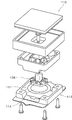
- FIG. 12 is an exploded perspective view of the power generation device / sensor unit 110 disclosed in Patent Document 1.
- FIG. 13 is a longitudinal sectional view of the power generator / sensor unit 110 at rest.
- the piezoelectric element 111 is disposed in the housing 112.
- the piezoelectric element 111 has a piezoelectric ceramic disk 114.
- An actuator 136 is disposed on the piezoelectric ceramic disk 114.
- Patent Document 2 discloses a power generation device 200 shown in FIG. As shown in FIG. 14, the power generation device 200 includes a piezoelectric element 211 a and a metal plate 211 b that is joined to the piezoelectric element 211 a and also serves as an extraction electrode. The piezoelectric element 211a and the metal plate 211b are supported in a cantilever manner by the fixing portion 213. JP-T-2006-501098 JP 7-49388 A
- the piezoelectric power generation device described in Patent Document 1 has a complicated structure. For this reason, the piezoelectric power generation device described in Patent Document 1 is not only difficult to manufacture, but also has a high manufacturing cost.
- the generator described in Patent Document 2 has a simple structure as compared with the piezoelectric power generation apparatus described in Patent Document 1.
- the generator described in Patent Document 2 has a problem that sufficient mechanical strength cannot be obtained. For this reason, sufficient mechanical durability cannot be obtained in applications such as TPMS in which a relatively large force is applied to the piezoelectric element.
- An object of the present invention is to provide a piezoelectric power generator having a simple configuration and excellent mechanical durability.
- the power generation device includes a power generation element and a package member.
- the power generation element includes a plate-like piezoelectric element and a metal plate.
- the piezoelectric element has a pair of main surfaces facing each other.
- the metal plate is joined to one main surface of the piezoelectric element.
- the package member has a support portion and a restriction portion.
- the support portion supports the end portion of the power generation element in a cantilever manner.
- the restricting portion is disposed on the opposite side of the metal plate from the piezoelectric element. The restricting portion restricts the displacement of the power generating element to the outside of the metal plate.
- the package member includes a side wall portion serving as a support portion, a bottom wall portion serving as a restriction portion, and a ceiling disposed to face the bottom wall portion via a power generation element.
- the distance between the power generation element and the bottom wall is shorter than the distance between the power generation element and the ceiling.
- the restricting portion has a contact portion that contacts a surface of the metal plate opposite to the piezoelectric element.
- the contact portion is in contact with the metal plate at the end portion on the free end side of the power generation element.
- the contact portion biases the power generation element toward the piezoelectric element.
- the piezoelectric power generation device further includes a buffer member disposed between the package member and the power generation element.
- the piezoelectric power generation device further includes a conductive layer bonded to the other main surface of the piezoelectric element.
- the piezoelectric element has a piezoelectric body substantially made of piezoelectric ceramics.
- the piezoelectric power generation device according to the present invention may be attached to the inner peripheral surface side of the tire. (The invention's effect)
- a restricting portion that restricts the displacement of the power generating element to the outside of the metal plate is provided, and since it is suppressed that a large tensile stress is applied to the piezoelectric element, it has a simple structure and is therefore inexpensive. In addition, a piezoelectric power generation device having excellent mechanical durability can be realized.
- FIG. 1 is a cross-sectional view of the piezoelectric power generation apparatus according to the first embodiment.
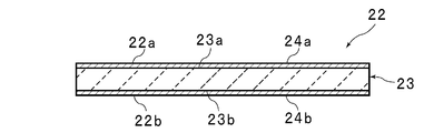
- FIG. 2 is a cross-sectional view of the piezoelectric element.
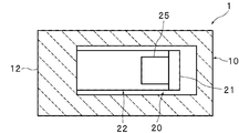
- 3 is a view taken in the direction of arrows III-III in FIG.
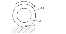
- FIG. 4 is a schematic explanatory diagram for explaining the force applied to the piezoelectric power generator when the tire rotates.
- FIG. 5 is a schematic explanatory diagram for explaining the force applied to the piezoelectric power generation device when the tire rotates.
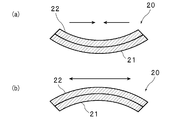
- FIG. 6 is a cross-sectional view showing a piezoelectric element in a vibrating state.
- FIG. 7 is a cross-sectional view of the piezoelectric power generation device according to the second embodiment.
- FIG. 1 is a cross-sectional view of the piezoelectric power generation apparatus according to the first embodiment.
- FIG. 2 is a cross-sectional view of the piezoelectric element.
- 3 is a view taken in the direction of arrows III
- FIG. 8 is a cross-sectional view of the piezoelectric power generating device according to the third embodiment.
- FIG. 9 is a cross-sectional view of the piezoelectric power generating device according to the fourth embodiment.
- FIG. 10 is a cross-sectional view of the piezoelectric power generating device according to the fifth embodiment.
- FIG. 11 is a cross-sectional view of a piezoelectric power generator according to a modification.
- FIG. 12 is an exploded perspective view of the power generation device / sensor unit disclosed in Patent Document 1.
- FIG. 13 is a longitudinal sectional view of the power generation device / sensor unit at rest.
- FIG. 14 is a configuration diagram illustrating a main part of the generator disclosed in Patent Document 2.
- FIG. 1 is a cross-sectional view of the piezoelectric power generation apparatus 1 according to the first embodiment.
- the piezoelectric power generation apparatus 1 is an apparatus that is attached to a rotating body such as a tire and generates power as the rotating body rotates.
- the piezoelectric power generator 1 is used as a power source for TPMS, for example.
- the piezoelectric power generation device 1 includes a power generation element 20 and a package member 10.
- the power generation element 20 includes a unimorph piezoelectric element 22, a metal plate 21, and a weight 25.
- the piezoelectric element 22 is plate-shaped and has a first main surface 22a and a second main surface 22b. As shown in FIG. 3, the piezoelectric element 22 is formed in a rectangular shape in plan view. However, the planar view shape of the piezoelectric element 22 is not particularly limited.
- the piezoelectric element 22 includes a plate-like piezoelectric body 23 and electrodes 24a and 24b. In FIG. 1 and the like, illustration of the electrodes 24a and 24b is omitted.
- the piezoelectric body 23 may be made of, for example, piezoelectric ceramics. Specific examples of piezoelectric ceramics include, for example, lead zirconate titanate ceramics.
- the piezoelectric body 23 is polarized in the thickness direction.
- the piezoelectric body 23 has a first main surface 23a and a second main surface 23b that face each other.
- An electrode 24 a is provided on the first main surface 23 a of the piezoelectric body 23.
- an electrode 24 b is provided on the second main surface 23 b of the piezoelectric body 23.
- the electrodes 24a and 24b are made of a conductive material such as a metal or an alloy.
- the formation method of the electrodes 24a and 24b is not particularly limited.
- the electrode 24 can be formed by, for example, baking a conductive paste, or a thin film forming method such as vapor deposition, sputtering, or plating.
- the metal plate 21 is bonded to the second main surface 22 b of the piezoelectric element 22. Specifically, the metal plate 21 is joined to the electrode 24b.
- the metal plate 21 and the electrode 24b may be insulated from each other or may not be insulated from each other.
- the thicknesses of the piezoelectric element 22 and the metal plate 21 are not particularly limited.
- the thickness of each of the piezoelectric element 22 and the metal plate 21 is preferably such that the piezoelectric power generation apparatus 1 vibrates with the rotation of the rotating body.
- a weight 25 is attached to one end 20b of the piezoelectric element 22.
- the weight 25 is for promoting vibration of the power generation element 20.
- the weight 25 is not necessarily provided.
- the power generating element 20 is supported by the package member 10 in a cantilever manner.
- the package member 10 is made of an insulating material. Examples of the material of the package member 10 include insulating ceramics.
- the package member 10 includes a bottom wall portion 11 as a restriction portion, a side wall portion 12 as a support portion, and a ceiling portion 13 that faces the bottom wall portion 11.
- the bottom wall portion 11, the side wall portion 12, and the ceiling portion 13 form a space 14 in which the power generating element 20 is disposed.
- the bottom wall portion 11 and the side wall portion 12 are integrally formed.
- the ceiling part 13 is formed separately from the side wall part 12 and the bottom wall part 11.
- the side wall part 12 as a support part supports one end part 20a in the length direction of the power generation element 20 in a cantilever manner. Thereby, in a state where the piezoelectric power generation device 1 is stationary, the power generation element 20 is installed substantially in parallel with the bottom wall portion 11 and the ceiling portion 13.
- the distance L2 between the power generation element 20 and the bottom wall portion 11 is set to be shorter than the distance L1 between the power generation element 20 and the ceiling portion 13.
- the distance L2 may be 0.
- the piezoelectric element 22 is weak against tensile stress as compared with compressive stress. Specifically, the piezoelectric element 22 exhibits brittleness when a tensile stress is applied. For this reason, for example, as shown in FIG. 6A, even if the power generating element 20 is displaced so as to be convex toward the metal plate 21, and the compressive stress is applied to the piezoelectric element 22, the piezoelectric element 22 is not easily damaged. On the other hand, as shown in FIG. 6B, when the power generating element 20 is displaced so as to be convex toward the piezoelectric element 22 and tensile stress is applied to the piezoelectric element 22, the piezoelectric element 22 is easily damaged. . This tendency is particularly remarkable when the piezoelectric body 23 is substantially made of piezoelectric ceramics.
- the distance between the piezoelectric element 211a and the package and the distance between the metal plate 211b and the package are substantially the same.
- the piezoelectric element 211a and the metal plate 211b can be largely displaced in both a direction in which a tensile stress is applied to the piezoelectric element 211a and a direction in which a compressive stress is applied to the piezoelectric element 211a.
- the piezoelectric element 211a and the metal plate 211b may be greatly displaced in a direction in which a tensile stress is applied to the piezoelectric element 211a, and a large tensile stress may be applied to the piezoelectric element 211a.
- the distance L2 between the power generation element 20 and the bottom wall portion 11 is set to be shorter than the distance L1 between the power generation element 20 and the ceiling portion 13.
- the bottom wall part 11 functions as a restricting part, and the power generating element 20 is restricted from being greatly displaced toward the metal plate 21 side where tensile stress is applied to the piezoelectric element 22. Therefore, a large tensile stress is suppressed from being applied to the piezoelectric element 22. Therefore, the mechanical durability of the piezoelectric generator 1 can be enhanced.
- the piezoelectric element 22 is particularly brittle when a tensile stress is applied. Therefore, the technique of this embodiment is particularly effective when the piezoelectric body 23 is substantially made of piezoelectric ceramics.
- the distance L ⁇ b> 2 between the power generation element 20 and the bottom wall portion 11 A method of reducing both the distance L1 between the ceiling portion 13 and the ceiling portion 13 can also be considered. However, when both the distances L1 and L2 are reduced, the amount of displacement of the power generating element 20 is reduced. For this reason, the power generation amount tends to be small.
- the distance L2 between the power generation element 20 and the bottom wall portion 11 is set small, but the distance L1 between the power generation element 20 and the ceiling portion 13 is set large.
- the power generation element 20 can be largely displaced toward the piezoelectric element 22 side. Therefore, compared with the case where both distance L1, L2 is made small, the electric power generation amount in the electric power generation element 20 can be made comparatively large. That is, according to the present embodiment, it is possible to obtain a relatively large power generation amount while enhancing the mechanical durability of the piezoelectric power generation device 1.
- the direction of the electric field generated in the piezoelectric body 23 when the power generating element 20 is displaced to the side where the tensile stress is applied to the piezoelectric element 22 and when the power generating element 20 is displaced to the side where the compressive stress is applied to the piezoelectric element 22. Is reversed. For this reason, generation
- the distance L2 between the power generation element 20 and the bottom wall portion 11 is small. Further, from the viewpoint of suppressing the power generating element 20 from being displaced to the side where the tensile stress is applied to the piezoelectric body 23, the distance L2 is preferably small. However, when the distance L2 decreases, the displacement of the power generation element 20 is suppressed, and the power generation efficiency tends to decrease. For this reason, from the viewpoint of obtaining high power generation efficiency, the distance L2 is preferably longer to some extent.
- FIG. 7 is a cross-sectional view of the piezoelectric power generation device 2 according to the second embodiment.
- the package member 10 includes the ceiling portion 13 in addition to the bottom wall portion 11 and the side wall portion 12 has been described.
- the package member 10 does not necessarily have the ceiling portion 13.
- the power generation element 20 may be disposed so as to contact the bottom wall portion 11. Specifically, as shown in FIG. 7, the power generating element 20 may be disposed such that the metal plate 21 contacts the surface 11 a of the bottom wall portion 11.
- the piezoelectric power generation device 2 of the present embodiment has a simple configuration as compared with the piezoelectric power generation device 3 shown in the following third embodiment, and can be manufactured easily and inexpensively.
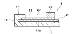
- FIG. 8 is a cross-sectional view of the piezoelectric power generation device 3 according to the third embodiment.
- the power generating element 20 may be in contact with the bottom wall portion 11 in part.
- the power generation element 20 may be in contact with the bottom wall portion 11 at the end 20b on the free end side.
- the power generation element 20 is disposed above the surface 11 a of the bottom wall portion 11.
- An air layer is interposed between the power generation element 20 and the surface 11a.
- a convex contact portion 11 b is formed on the bottom wall portion 11. The contact portion 11b is in contact with the end portion 20b on the free end side of the power generation element 20.
- the contact part when providing the contact part which contact
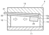
- the power generation element 20 may be in contact with the ceiling portion 13 like the piezoelectric power generation element 4 shown in FIG. That is, the bottom wall 11 may be attached to the inner peripheral surface of the tire, or the ceiling 13 may be attached to the inner peripheral surface of the tire.
- the surface of the package member 10 that contacts the power generation element 20 may not be flat.
- the surface 13a of the ceiling portion 13 is formed in a shape that curves toward the power generation element 20 as the distance from the portion of the side wall 12 where the power generation element 20 is attached. For this reason, the power generation element 20 is urged toward the piezoelectric element 22 by the ceiling portion 13 as the contact portion. Therefore, a compressive stress is always applied to the piezoelectric element 22. Therefore, it is possible to more reliably inhibit the tensile stress from being applied to the piezoelectric element 22, and the mechanical durability of the piezoelectric generator 4 can be further enhanced.
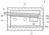
- FIG. 10 is a cross-sectional view of the piezoelectric power generation device 5 according to the fifth embodiment.
- buffer members 40 a and 40 b may be disposed between the power generation element 20 and the package member 10.
- the buffer member 40 a is disposed between the ceiling portion 13 as the restricting portion and the metal plate 21.
- the buffer member 40 b is disposed on the inner surface of the bottom wall portion 11.
- the buffer members 40a and 40b By arranging the buffer members 40a and 40b, a direct collision between the power generation element 20 and the package member 10 can be suppressed. Therefore, the force applied to the power generation element 20 can be more effectively reduced. Therefore, the mechanical durability of the piezoelectric generator 5 can be further enhanced.
- buffer member 40 for example, silicon rubber or the like can be used.
- a conductive layer 41 bonded to the surface of the piezoelectric element 22 opposite to the metal plate 21 may be further provided. That is, the conductive layer 41 may be bonded to the surface of the electrode 24a. By doing so, for example, even when a crack or the like occurs in the piezoelectric element 22, it is possible to ensure electrical connection more reliably.
- the material of the conductive layer 41 is not particularly limited.
- the conductive layer 41 may be made of, for example, a metal or an alloy.
- the conductive layer 41 is preferably a relatively thick metal foil or alloy foil. This is because the electrical connection can be particularly ensured.
- the planar shape of the piezoelectric element 22 is not particularly limited. As shown in FIG. 11, the planar shape of the piezoelectric element 22 may be, for example, a circle.
Landscapes
- Engineering & Computer Science (AREA)
- Mechanical Engineering (AREA)
- General Electrical Machinery Utilizing Piezoelectricity, Electrostriction Or Magnetostriction (AREA)
Abstract
Description
(発明の効果)
2 …圧電発電装置
3 …圧電発電装置
4 …圧電発電素子
5 …圧電発電装置
10 …パッケージ部材
11 …底壁部(規制部)
11b…当接部
12 …側壁部(支持部)
13 …天井部(規制部)
20 …発電素子
20b…自由端側の端部
21 …金属板
22 …圧電素子
23 …圧電体
24 …電極
25 …ウェイト
30 …タイヤ
30a…タイヤの内周面
40 …緩衝部材
41 …導電層
図1は、第1の実施形態に係る圧電発電装置1の断面図である。圧電発電装置1は、タイヤなどの回転体に対して取り付けられ、回転体の回転に伴って発電する装置である。圧電発電装置1は、例えば、TPMSの電源などとして用いられる。
図7は、第2の実施形態に係る圧電発電装置2の断面図である。
図8は、第3の実施形態に係る圧電発電装置3の断面図である。
上記第2の実施形態では、発電素子20が底壁部11に当接する例について説明した。但し、発電素子20は、図9に示す圧電発電素子4のように、天井部13に当接していてもよい。すなわち、底壁部11においてタイヤの内周面に取り付けられてもよく、天井部13においてタイヤの内周面に取り付けられてもよい。
図10は、第5の実施形態に係る圧電発電装置5の断面図である。図10に示すように、発電素子20とパッケージ部材10との間に緩衝部材40a、40bを配置してもよい。具体的には、緩衝部材40aは、規制部としての天井部13と金属板21との間に配置されている。緩衝部材40bは、底壁部11の内側の表面上に配置されている。
上記実施形態では、圧電素子22が矩形板状である例について説明した。但し、圧電素子22の平面形状は、特に限定されない。図11に示すように、圧電素子22の平面形状は、例えば円形であってもよい。
Claims (9)
- 互いに対向し合う一対の主面を有する板状の圧電素子と、前記圧電素子の一方の主面に接合された金属板とを有する発電素子と、
前記発電素子の端部を片持ち梁態様で支持する支持部と、前記金属板の前記圧電素子とは反対側に配置され、前記発電素子の前記金属板の外側への変位を規制する規制部とを有するパッケージ部材と、
を備える圧電発電装置。 - 前記パッケージ部材は、前記支持部としての側壁部と、前記規制部としての底壁部と、前記底壁部に対して、前記発電素子を介して対向するように配置された天井部とを有し、
前記発電素子と前記底壁部との間の距離は、前記発電素子と前記天井部との間の距離よりも短い、請求項1に記載の圧電発電装置。 - 前記規制部は、前記金属板の前記発電素子とは反対側の面と当接する当接部を有する、請求項1または2に記載の圧電発電装置。
- 前記当接部は、前記発電素子の自由端側の端部において前記金属板と当接している、請求項3に記載の圧電発電装置。
- 前記当接部は、前記発電素子を前記圧電素子側に付勢している、請求項3または4に記載の圧電発電装置。
- 前記パッケージ部材と前記発電素子との間に配置された緩衝部材をさらに備える、請求項1または2に記載の圧電発電装置。
- 前記圧電素子の他方の主面に接合された導電層をさらに備える、請求項1~6のいずれか一項に記載の圧電発電装置。
- 前記圧電素子は、実質的に圧電セラミックスからなる圧電体を有する、請求項1~7のいずれか一項に記載の圧電発電装置。
- タイヤの内周面側に取り付けられる、請求項1~8のいずれか一項に記載の圧電発電装置。
Priority Applications (4)
| Application Number | Priority Date | Filing Date | Title |
|---|---|---|---|
| CN2009801114204A CN101981801B (zh) | 2008-04-01 | 2009-03-30 | 压电发电装置 |
| EP09727575A EP2262094A4 (en) | 2008-04-01 | 2009-03-30 | PIEZOELECTRIC POWER GENERATION UNIT |
| JP2010505379A JP5316533B2 (ja) | 2008-04-01 | 2009-03-30 | 圧電発電装置 |
| US12/891,130 US8174168B2 (en) | 2008-04-01 | 2010-09-27 | Piezoelectric power generating device |
Applications Claiming Priority (2)
| Application Number | Priority Date | Filing Date | Title |
|---|---|---|---|
| JP2008094848 | 2008-04-01 | ||
| JP2008-094848 | 2008-04-01 |
Related Child Applications (1)
| Application Number | Title | Priority Date | Filing Date |
|---|---|---|---|
| US12/891,130 Continuation US8174168B2 (en) | 2008-04-01 | 2010-09-27 | Piezoelectric power generating device |
Publications (1)
| Publication Number | Publication Date |
|---|---|
| WO2009122703A1 true WO2009122703A1 (ja) | 2009-10-08 |
Family
ID=41135108
Family Applications (1)
| Application Number | Title | Priority Date | Filing Date |
|---|---|---|---|
| PCT/JP2009/001437 Ceased WO2009122703A1 (ja) | 2008-04-01 | 2009-03-30 | 圧電発電装置 |
Country Status (5)
| Country | Link |
|---|---|
| US (1) | US8174168B2 (ja) |
| EP (1) | EP2262094A4 (ja) |
| JP (1) | JP5316533B2 (ja) |
| CN (1) | CN101981801B (ja) |
| WO (1) | WO2009122703A1 (ja) |
Cited By (3)
| Publication number | Priority date | Publication date | Assignee | Title |
|---|---|---|---|---|
| JP2012210090A (ja) * | 2011-03-30 | 2012-10-25 | Seiko Epson Corp | 圧電型発電機とその製造方法、及びセンサーノード |
| JPWO2012073656A1 (ja) * | 2010-12-01 | 2014-05-19 | 株式会社村田製作所 | 圧電発電装置及びその製造方法 |
| KR20160030655A (ko) * | 2014-09-11 | 2016-03-21 | 한국전자통신연구원 | 에너지 하베스팅 소자, 그의 제조방법, 및 그를 포함하는 무선 장치 |
Families Citing this family (16)
| Publication number | Priority date | Publication date | Assignee | Title |
|---|---|---|---|---|
| JP5120496B2 (ja) * | 2009-04-15 | 2013-01-16 | 株式会社村田製作所 | 圧電発電装置 |
| WO2012002121A1 (ja) * | 2010-07-02 | 2012-01-05 | 株式会社村田製作所 | 圧電発電装置 |
| FI123941B (fi) * | 2010-09-07 | 2013-12-31 | Murata Electronics Oy | Energiankerääjärakenne ja -menetelmä |
| CN102185520B (zh) * | 2011-04-01 | 2013-04-03 | 浙江师范大学 | 遥控器用等曲率悬臂梁压电发电装置 |
| US8072122B2 (en) * | 2011-05-03 | 2011-12-06 | Hong Kong Applied Science and Technology Research Institute Company Limited | Self-powered impulse detection system with piezoelectric energy harvester |
| US9368710B2 (en) * | 2011-05-17 | 2016-06-14 | Georgia Tech Research Corporation | Transparent flexible nanogenerator as self-powered sensor for transportation monitoring |
| US9054294B2 (en) * | 2011-10-06 | 2015-06-09 | Texas Instruments Incorporated | Soft mechanical stops to limit over-travel of proof masses in cantilevered piezoelectric devices |
| CN103241989A (zh) * | 2012-02-03 | 2013-08-14 | 钡泰电子陶瓷股份有限公司 | 压电复合材料的制法及压电发电装置 |
| CN103287101B (zh) * | 2012-02-23 | 2015-12-02 | 珠海赛纳打印科技股份有限公司 | 压电促动器及液体喷头 |
| CN103166503B (zh) * | 2013-03-06 | 2016-05-25 | 武汉理工大学 | 一种用于公交车的压电俘能装置 |
| JP6229060B2 (ja) | 2013-08-16 | 2017-11-08 | 株式会社エーエムシー・エナジー | 反発力を利用した圧電ハーベスティングシステム |
| JP6406538B2 (ja) * | 2014-06-17 | 2018-10-17 | Toto株式会社 | トイレ装置用のリモコン装置 |
| CN104124894A (zh) * | 2014-08-06 | 2014-10-29 | 苏州科技学院 | 一种基于楼梯的压电发电装置 |
| EP3285390B1 (en) * | 2015-04-13 | 2021-03-24 | Murata Manufacturing Co., Ltd. | Piezoelectric power generator |
| US10633220B2 (en) | 2017-07-20 | 2020-04-28 | Michael Van Deurse | Monitoring system for pneumatic core shafts and shaft adapters |
| CN113167565A (zh) * | 2018-12-17 | 2021-07-23 | 阿尔卑斯阿尔派株式会社 | 复合压电元件、轮胎状态测定装置、轮胎传感器模块、轮胎传感器装置以及压电传感器 |
Citations (9)
| Publication number | Priority date | Publication date | Assignee | Title |
|---|---|---|---|---|
| JPS59194677A (ja) * | 1983-03-28 | 1984-11-05 | インペリアル・クレバイト・インコ−ポレイテツド | 圧電変換器電源 |
| JPH0749388A (ja) | 1993-08-04 | 1995-02-21 | Seiko Epson Corp | 発電機 |
| JP2003218418A (ja) * | 2002-01-18 | 2003-07-31 | Matsushita Electric Ind Co Ltd | 圧電型発電器 |
| JP2004266033A (ja) | 2003-02-28 | 2004-09-24 | Taiheiyo Cement Corp | 圧電装置 |
| JP2005045988A (ja) | 2003-07-22 | 2005-02-17 | Akimasa Shinoyama | 携帯発電装置 |
| JP2005057982A (ja) | 2003-08-07 | 2005-03-03 | Akimasa Shinoyama | 振り子式圧電素子発電装置 |
| JP2006501098A (ja) | 2002-10-01 | 2006-01-12 | ピエゾタグ リミテッド | 遠隔測定ユニット |
| WO2006072539A2 (de) | 2005-01-07 | 2006-07-13 | Continental Teves Ag & Co. Ohg | Reifenmodul sowie luftreifen mit reifenmodul |
| JP2007282355A (ja) * | 2006-04-05 | 2007-10-25 | Murata Mfg Co Ltd | 圧電発電装置 |
Family Cites Families (15)
| Publication number | Priority date | Publication date | Assignee | Title |
|---|---|---|---|---|
| US4093885A (en) * | 1976-03-19 | 1978-06-06 | Ampex Corporation | Transducer assembly vibration sensor |
| US4387318A (en) * | 1981-06-04 | 1983-06-07 | Piezo Electric Products, Inc. | Piezoelectric fluid-electric generator |
| US5539270A (en) * | 1993-11-19 | 1996-07-23 | Matsushita Electric Works, Ltd. | Acceleration detector |
| JP2993459B2 (ja) * | 1997-03-25 | 1999-12-20 | セイコーエプソン株式会社 | 発電機および携帯用機器 |
| JPH11258262A (ja) * | 1998-03-10 | 1999-09-24 | Hitachi Metals Ltd | 圧電センサ |
| US6252336B1 (en) * | 1999-11-08 | 2001-06-26 | Cts Corporation | Combined piezoelectric silent alarm/battery charger |
| JP2005312269A (ja) * | 2004-04-26 | 2005-11-04 | Nec Corp | 振動による発電方法および振動式発電機および振動式発電装置 |
| JP4761459B2 (ja) * | 2006-04-10 | 2011-08-31 | Necトーキン株式会社 | 圧電振動ユニット及び圧電式スピーカ |
| JP2007300426A (ja) * | 2006-04-28 | 2007-11-15 | Sony Corp | 圧電振動子およびこれを備えた圧電振動発生装置 |
| US7414351B2 (en) * | 2006-10-02 | 2008-08-19 | Robert Bosch Gmbh | Energy harvesting device manufactured by print forming processes |
| CN100449813C (zh) * | 2006-10-24 | 2009-01-07 | 北京科技大学 | 一种功能梯度结构的压电驱动器件及其制备方法 |
| EP2109931B1 (en) * | 2007-01-29 | 2015-03-11 | Drexel University | Energy harvesting device |
| US8011237B2 (en) * | 2008-02-22 | 2011-09-06 | Hong Kong Applied Science And Technology Research Institute Co., Ltd. | Piezoelectric module for energy harvesting, such as in a tire pressure monitoring system |
| JP2009247128A (ja) * | 2008-03-31 | 2009-10-22 | Taiyo Yuden Co Ltd | 圧電振動型発電機 |
| CN101262189A (zh) * | 2008-04-18 | 2008-09-10 | 南京航空航天大学 | 收集弯曲振动能量的压电式发电机 |
-
2009
- 2009-03-30 WO PCT/JP2009/001437 patent/WO2009122703A1/ja not_active Ceased
- 2009-03-30 JP JP2010505379A patent/JP5316533B2/ja active Active
- 2009-03-30 CN CN2009801114204A patent/CN101981801B/zh active Active
- 2009-03-30 EP EP09727575A patent/EP2262094A4/en not_active Withdrawn
-
2010
- 2010-09-27 US US12/891,130 patent/US8174168B2/en active Active
Patent Citations (9)
| Publication number | Priority date | Publication date | Assignee | Title |
|---|---|---|---|---|
| JPS59194677A (ja) * | 1983-03-28 | 1984-11-05 | インペリアル・クレバイト・インコ−ポレイテツド | 圧電変換器電源 |
| JPH0749388A (ja) | 1993-08-04 | 1995-02-21 | Seiko Epson Corp | 発電機 |
| JP2003218418A (ja) * | 2002-01-18 | 2003-07-31 | Matsushita Electric Ind Co Ltd | 圧電型発電器 |
| JP2006501098A (ja) | 2002-10-01 | 2006-01-12 | ピエゾタグ リミテッド | 遠隔測定ユニット |
| JP2004266033A (ja) | 2003-02-28 | 2004-09-24 | Taiheiyo Cement Corp | 圧電装置 |
| JP2005045988A (ja) | 2003-07-22 | 2005-02-17 | Akimasa Shinoyama | 携帯発電装置 |
| JP2005057982A (ja) | 2003-08-07 | 2005-03-03 | Akimasa Shinoyama | 振り子式圧電素子発電装置 |
| WO2006072539A2 (de) | 2005-01-07 | 2006-07-13 | Continental Teves Ag & Co. Ohg | Reifenmodul sowie luftreifen mit reifenmodul |
| JP2007282355A (ja) * | 2006-04-05 | 2007-10-25 | Murata Mfg Co Ltd | 圧電発電装置 |
Non-Patent Citations (1)
| Title |
|---|
| See also references of EP2262094A4 |
Cited By (4)
| Publication number | Priority date | Publication date | Assignee | Title |
|---|---|---|---|---|
| JPWO2012073656A1 (ja) * | 2010-12-01 | 2014-05-19 | 株式会社村田製作所 | 圧電発電装置及びその製造方法 |
| JP2012210090A (ja) * | 2011-03-30 | 2012-10-25 | Seiko Epson Corp | 圧電型発電機とその製造方法、及びセンサーノード |
| KR20160030655A (ko) * | 2014-09-11 | 2016-03-21 | 한국전자통신연구원 | 에너지 하베스팅 소자, 그의 제조방법, 및 그를 포함하는 무선 장치 |
| KR102229140B1 (ko) | 2014-09-11 | 2021-03-18 | 한국전자통신연구원 | 에너지 하베스팅 소자, 그의 제조방법, 및 그를 포함하는 무선 장치 |
Also Published As
| Publication number | Publication date |
|---|---|
| US8174168B2 (en) | 2012-05-08 |
| EP2262094A1 (en) | 2010-12-15 |
| CN101981801A (zh) | 2011-02-23 |
| CN101981801B (zh) | 2013-08-28 |
| US20110012479A1 (en) | 2011-01-20 |
| JP5316533B2 (ja) | 2013-10-16 |
| JPWO2009122703A1 (ja) | 2011-07-28 |
| EP2262094A4 (en) | 2012-12-12 |
Similar Documents
| Publication | Publication Date | Title |
|---|---|---|
| JP5316533B2 (ja) | 圧電発電装置 | |
| CN102144355B (zh) | 压电发电装置 | |
| CN103238271B (zh) | 压电发电装置及其制造方法 | |
| WO2011083762A1 (ja) | 圧電発電素子および圧電発電素子を用いた発電方法 | |
| JP5120496B2 (ja) | 圧電発電装置 | |
| KR101578806B1 (ko) | 배터리를 포함하는 플렉서블 압전 스피커 | |
| JP6731268B2 (ja) | 静電型トランスデューサ | |
| KR101663089B1 (ko) | 압전 소자 및 압전 스피커 | |
| EP2693771B1 (en) | Oscillator and electronic device | |
| WO2016147917A1 (ja) | 超音波センサ | |
| JP4830592B2 (ja) | 圧電発電装置 | |
| CN107113510B (zh) | 超声波传感器 | |
| JP5134431B2 (ja) | 発音体 | |
| JP5741703B2 (ja) | 超音波トランスデューサー | |
| WO2011136312A1 (ja) | 振動発電デバイスおよびその製造方法 | |
| US20130034252A1 (en) | Transducer module | |
| JP2007041110A (ja) | 透明な制御対象板用振動・騒音低減デバイス及び透明窓用振動・騒音低減装置 | |
| JP5447693B2 (ja) | 加速度センサ | |
| JP5513239B2 (ja) | 電気機械変換装置及びその製造方法 | |
| JP5195619B2 (ja) | 半導体基板 | |
| JP6692892B2 (ja) | ハウジングおよびこのハウジングに配置されたダイヤフラムエレメントを有する音響センサ | |
| JP6044155B2 (ja) | ピックアップ機能付サドル | |
| JP2006135924A (ja) | 圧電発音体およびこれを用いた発音装置 | |
| JP2007107990A (ja) | 加速度センサ | |
| JP2003344438A (ja) | 衝撃センサ |
Legal Events
| Date | Code | Title | Description |
|---|---|---|---|
| WWE | Wipo information: entry into national phase |
Ref document number: 200980111420.4 Country of ref document: CN |
|
| 121 | Ep: the epo has been informed by wipo that ep was designated in this application |
Ref document number: 09727575 Country of ref document: EP Kind code of ref document: A1 |
|
| WWE | Wipo information: entry into national phase |
Ref document number: 2010505379 Country of ref document: JP |
|
| REEP | Request for entry into the european phase |
Ref document number: 2009727575 Country of ref document: EP |
|
| WWE | Wipo information: entry into national phase |
Ref document number: 2009727575 Country of ref document: EP |
|
| NENP | Non-entry into the national phase |
Ref country code: DE |