WO2009122724A1 - 画像処理装置および方法並びにプログラム - Google Patents
画像処理装置および方法並びにプログラム Download PDFInfo
- Publication number
- WO2009122724A1 WO2009122724A1 PCT/JP2009/001494 JP2009001494W WO2009122724A1 WO 2009122724 A1 WO2009122724 A1 WO 2009122724A1 JP 2009001494 W JP2009001494 W JP 2009001494W WO 2009122724 A1 WO2009122724 A1 WO 2009122724A1
- Authority
- WO
- WIPO (PCT)
- Prior art keywords
- pixel
- value
- setting target
- search point
- pixel value
- Prior art date
- Legal status (The legal status is an assumption and is not a legal conclusion. Google has not performed a legal analysis and makes no representation as to the accuracy of the status listed.)
- Ceased
Links
Images


Classifications
-
- G—PHYSICS
- G06—COMPUTING OR CALCULATING; COUNTING
- G06T—IMAGE DATA PROCESSING OR GENERATION, IN GENERAL
- G06T15/00—Three-dimensional [3D] image rendering
- G06T15/50—Lighting effects
- G06T15/503—Blending, e.g. for anti-aliasing
-
- A—HUMAN NECESSITIES
- A61—MEDICAL OR VETERINARY SCIENCE; HYGIENE
- A61B—DIAGNOSIS; SURGERY; IDENTIFICATION
- A61B6/00—Apparatus or devices for radiation diagnosis; Apparatus or devices for radiation diagnosis combined with radiation therapy equipment
- A61B6/46—Arrangements for interfacing with the operator or the patient
- A61B6/461—Displaying means of special interest
- A61B6/466—Displaying means of special interest adapted to display 3D data
-
- A—HUMAN NECESSITIES
- A61—MEDICAL OR VETERINARY SCIENCE; HYGIENE
- A61B—DIAGNOSIS; SURGERY; IDENTIFICATION
- A61B8/00—Diagnosis using ultrasonic, sonic or infrasonic waves
- A61B8/48—Diagnostic techniques
- A61B8/483—Diagnostic techniques involving the acquisition of a 3D volume of data
-
- G—PHYSICS
- G06—COMPUTING OR CALCULATING; COUNTING
- G06T—IMAGE DATA PROCESSING OR GENERATION, IN GENERAL
- G06T15/00—Three-dimensional [3D] image rendering
- G06T15/08—Volume rendering
Definitions
- the present invention relates to three-dimensional image processing, and more particularly to processing for generating a projection image from a three-dimensional image including a non-display target area.
- a projection image obtained by projecting a three-dimensional medical image obtained by a CT apparatus, an MRI apparatus, an ultrasonic diagnostic apparatus (echo) or the like onto a desired projection surface are performed.
- a method for obtaining such a projection image a plurality of search points are set in a three-dimensional medical image by setting a plurality of search points along the line of sight passing through an arbitrary viewpoint and each projection pixel on the projection plane.
- Image processing for obtaining the pixel value of the projection pixel for each line of sight based on the pixel value of the point is performed.
- MIP Maximum Intensity Projection
- MinIP Minimum
- Intensity Projection minimum value projection
- the position of each search point on the line of sight in the coordinate system of the three-dimensional image does not become an integer coordinate value. It may not be used as it is. In such a case, it is necessary to calculate the pixel value of each search point by interpolation calculation based on the pixel values of the pixels in the vicinity of each search point.
- the search point is naturally present in the display target region at the search point near the boundary between the two regions. Pixels in the vicinity of the point may belong to a region not to be displayed.
- FIG. 4 shows an example of such a case.
- one pixel Q (x 1 , y 2 ) among the eight neighboring pixels. , Z 2 ) is a pixel in a region not to be displayed.
- the calculated value is influenced by the pixel value of the neighboring pixel Q that is not originally a display target.
- a pixel that exceeds the pixel value threshold 100 is not a display target (non-display)
- a pixel value of the neighboring pixel Q is 200
- a pixel value of another neighboring pixel in the display target region
- the value of the area that should be excluded from the display target is larger than the threshold value that is the maximum pixel value.
- the pixel value of the search point is adopted on the line of sight including the search point, and appears as an artifact in the projection image
- the present invention has been made in view of such circumstances, and when generating a projection image obtained by projecting pixels in a three-dimensional image including an area not to be displayed, artifacts resulting from the area not to be displayed are removed.
- An object of the present invention is to provide an apparatus, a method, and a program that can be suppressed.
- the image processing apparatus sets a plurality of exploration points in the three-dimensional image along a plurality of lines of sight connecting each pixel on the projection plane onto which the three-dimensional image is projected and an arbitrary viewpoint,
- the pixel value of each search point is calculated by interpolation based on the pixel values of the neighboring pixels of the search point, and the pixel value of the pixel on the projection plane is determined for each line of sight based on the pixel value of the search point.
- An image processing apparatus comprising a projection image generating means for generating a projection image composed of each pixel on the projection plane, wherein the three-dimensional image includes a setting target region to be set as the search point, and
- the projection image generating means is divided into non-setting target areas that are not setting targets of the search points, and the projection image generating means, when the neighboring pixels of the search points are pixels of the non-setting target areas, In order to prevent the pixel value of the pixel from contributing, And characterized in that to calculate the pixel value.
- the image processing method of the present invention sets a plurality of exploration points in the three-dimensional image along a plurality of lines of sight connecting each pixel on the projection plane on which the three-dimensional image is projected and an arbitrary viewpoint,
- the pixel value of each search point is calculated by interpolation based on the pixel values of the neighboring pixels of the search point, and the pixel value of the pixel on the projection plane is determined for each line of sight based on the pixel value of the search point.
- the pixel value of the search point is a pixel in the non-target region when the pixel value of the search point is calculated
- the pixel of the neighboring pixel in the non-target region is calculated so that the value does not contribute.
- the Rukoto is
- an image processing program according to the present invention is for causing a computer to execute the above method.
- the “three-dimensional image” is divided into a setting target region that is a setting target of the search point and a non-setting target region that is not the setting target of the search point. It only needs to be set explicitly.
- the “setting target area” is an area that can be a display target when displaying a projection image generated from a three-dimensional image in the present invention.
- classification of setting target area and non-setting target area
- Specific methods of “classification (of setting target area and non-setting target area)” include a method of classifying both areas based on a magnitude relationship with a predetermined threshold, or an area extracted by a known image recognition process For example, a method of setting in one of the two areas.
- the projected image is based on a central projection method in which pixels in a three-dimensional image are projected along a plurality of lines of sight from one viewpoint.
- the image may be an image, or may be an image by a parallel projection method in which pixels in a three-dimensional image are projected along parallel lines of sight from a plurality of viewpoints.
- MIP Maximum Intensity Projection
- MinIP Minimum Intensity Projection processing to determine the minimum value of the pixel values of all exploration points on the line of sight, all on the line of sight
- Examples include a process for obtaining an average value of pixel values of search points, a volume rendering process using a ray casting method, and the like.
- the effect of the present invention is remarkable when a process for determining the pixel value of a specific exploration point on the line of sight as the pixel value of the pixel on the projection surface, such as the MIP process or the MinIP process, is used. Become.
- the process of “calculating the pixel value of the search point so that the pixel value of the neighboring pixel of the non-setting target region does not contribute when the neighboring pixel of the search point is a pixel of the non-setting target region” As a method, the pixel value of the neighboring pixel in the non-setting target region is replaced with another value, and in the interpolation calculation, the pixel value of the neighboring pixel in the non-setting target region uses the value after the replacement, It is conceivable that not only the pixel values of the neighboring pixels in the non-setting target area but also the existence of the pixel itself is excluded from the interpolation calculation, and the interpolation calculation is performed using only the neighboring pixels in the other setting target areas.
- a value calculated from the pixel value of the pixel in the setting target region using a predetermined method determined according to the method of determining the pixel value of the pixel on the projection plane a predetermined fixed value corresponding to a method for determining the pixel value of the pixel on the projection surface is conceivable.
- each of the maximum value, the minimum value, the average value, the median value, the mode value, and the setting target area of the pixels in the setting target area The class value of the most frequent class in the pixel value histogram of the pixel, the maximum value, the minimum value, the average value, and the center of the pixel values of the neighboring pixels in the setting target area at the search point for the neighboring pixels in the non-setting target area Value and the like.
- specific examples of the “predetermined fixed value” to be replaced include a maximum value and a minimum value in specifications such as quantization of the three-dimensional image.
- a plurality of exploration points are set in a three-dimensional image along a plurality of lines of sight connecting each pixel on a projection plane onto which a three-dimensional image is projected and an arbitrary viewpoint, Is calculated by interpolation based on the pixel values of the neighboring pixels of the search point, and the pixel value of the pixel on the projection plane is determined for each line of sight based on the calculated pixel value, and each pixel on the projection plane is determined.
- the search is performed so that the pixel value of the pixel near the non-setting area does not contribute: Since the pixel value of the point is calculated, the pixel value of the pixel in the region not to be set does not affect the determination of the pixel value of each pixel on the projection plane, which is caused by the region not to be set Artifacts are suppressed.
- a process of determining the pixel value of a specific exploration point on the line of sight as the pixel value of the pixel on the projection plane such as MIP processing or MinIP processing.
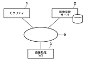
- FIG. 1 is a hardware configuration diagram showing an overview of a three-dimensional medical image processing system. As shown in the figure, in this system, a modality 1, an image storage server 2, and an image processing workstation 3 are connected via a network 9 in a communicable state.
- the modality 1 acquires a three-dimensional medical image V representing a subject, and specifically includes a CT apparatus, an MRI apparatus, an ultrasonic diagnostic apparatus, and the like.
- the image storage server 2 is a computer that stores and manages a three-dimensional medical image V acquired by the modality 1 and a medical image generated by image processing at the image processing workstation 3 in an image database.
- database management software for example, ORDB (Object Relational Database) management software.
- the image processing workstation 3 is a computer that performs image processing on the three-dimensional medical image V acquired from the modality 1 or the image storage server 2 in response to a request from the interpreter and displays the generated image.
- it includes an input device such as a keyboard and a mouse for inputting a request from a radiogram interpreter, a main memory having a capacity capable of storing the acquired three-dimensional medical image V, and a display for displaying the generated image. .
- the storage format of image data and communication between devices via the network 9 are based on a protocol such as DICOM (Digital Imaging and Communications Communications in Medicine).
- DICOM Digital Imaging and Communications Communications in Medicine
- FIG. 2 is a block diagram showing portions related to the projection image generation function of the image processing workstation 3.
- the image processing workstation 3 acquires an image acquisition unit 10 that acquires a three-dimensional medical image V of a patient to be interpreted from the modality 1 or the image storage server 2 in response to a request from the interpreter.
- a display setting unit 20 that sets a display target region and a non-display target region in the three-dimensional medical image V, and a plurality of lines of sight connecting the arbitrary viewpoint and each pixel on the projection plane.
- a plurality of exploration points are set in the display target area, and based on the pixel values of all exploration points on the line of sight, the pixel values of the pixels on the projection plane projected by the line of sight are determined, and a projection image is obtained.
- the projection image generation unit 60 includes an exploration point setting unit 30, a pixel value calculation unit 40, a projection And a decision unit 50.
- the image acquisition unit 10 acquires a three-dimensional medical image V of a patient to be interpreted from the modality 1 or the image storage server 2 in response to a request from an interpreter.
- the three-dimensional medical image V is obtained by dividing a multi-slice image into pixels (voxels) and arranging the pixels in a three-dimensional coordinate space. Is defined in a three-dimensional coordinate system in which the vertical axis is the y-axis and the vertical direction is the z-axis, and the pixel value of each pixel is associated with the coordinates of the position of the pixel.
- the display setting unit 20 includes a display target region (search point setting target region) and a non-display target region (search point non-target setting region) in the three-dimensional medical image V acquired by the image acquisition unit 10.
- a display target region search point setting target region
- a non-display target region search point non-target setting region
- the image interpreter has display / non-display information in each pixel of the 3D medical image V. Create a mask.
- the pixel value of the pixel in the non-display target region is set to be larger / smaller than the pixel value of the pixel of the display target region, or a change in pixel value or opacity (such as edge information)
- a change in pixel value or opacity such as edge information
- a plurality of sample images including a target region to be extracted are machine-learned in advance, and the biological tissue is extracted from the three-dimensional medical image V based on the learned result.
- the display target region and the non-display target region can also be set in the three-dimensional medical image V by a method different from the method exemplified above, such as setting to be displayed or hidden separately from the region.
- the projection image generation unit 60 receives the three-dimensional medical image V in which the display target region and the non-display target region are set as input, and the search point setting unit 30, the pixel value calculation unit 40, and the projection value determination unit 50 The pixel values (output pixel values) of the pixels constituting the projection image are obtained.
- the exploration point setting unit 30 uses, for example, the initial setting file, the viewpoint set by the input from the keyboard or mouse by the image reader, the projection plane F (size, position, number of pixels), for example, as shown in FIG.
- a plurality of exploration points P ji (i 1, 2,..., N; n is the number of exploration points on the line of sight E j ) sampled in (1).
- the pixel value calculation unit 40 refers to the mask having the display / non-display information of each pixel created in the display setting unit 20, and the eight pixels (neighbors near the search points P ji ). It is determined whether or not each pixel is a pixel set to non-display (a pixel in the non-display target area), and in the case of a pixel set to non-display, the pixel value of its neighboring pixels is described later. After that, the pixel value g (P ji ) at each search point P ji is calculated by interpolation based on the pixel values of the neighboring pixels of the search point.
- This replacement process is for calculating the pixel value of the search point P ji so that the pixel values of neighboring pixels in the non-display target region do not contribute.
- the projection value determination unit 50 to be described later determines the projection value by MIP / MinIP processing
- the pixel value of the neighboring pixel in the non-display target area is set to the maximum pixel value of all the pixels in the display target area / It can be replaced with the minimum value, or can be replaced with the maximum value / minimum value of the pixel values of the neighboring pixels in the display target area at the search point for the neighboring pixels.
- the display setting unit 20 is set so that pixels exceeding the threshold value 100 of the pixel value are excluded from the display target, and the neighboring pixels of the search point P ji are displayed in the display target region as shown in FIG.
- 90, 95, 95, and the pixel value of the pixel belonging to the non-display target area is 200
- the pixel value of the pixel Q of the non-display target area is set to the pixel of another neighboring pixel belonging to the display target area.
- the maximum value 95 of the values may be replaced.
- the pixel value of the pixel Q may be replaced with the average value of the pixel values of other neighboring pixels belonging to the display target region, or 0 for the MIP processing and the maximum possible value for the MinIP processing. It may be replaced with a fixed value such as a pixel value.
- the pixel value g (P ji ) at each search point P ji is obtained by linearly interpolating the pixel values of eight neighboring pixels constituting the grid including the search point P ji .
- the pixel value g (x, y, z) is obtained by the following equation (1).
- the pixel values of the neighboring pixels in the non-display target area are the pixel values after the above replacement process.
- the pixel value g (P ji ) at each search point P ji is obtained by linearly interpolating the pixel values of the eight pixels constituting the grid including the search point P ji. Then, the pixel values of 64 pixels (4 pixels in the x-axis direction ⁇ 4 pixels in the y-axis direction ⁇ 4 pixels in the z-axis direction) constituting the grid including the search point P ji are subjected to cubic interpolation. You may make it ask.
- the projection value determination unit 50 determines the output pixel value C j of each pixel on the projection plane based on the pixel value g (P ji ) at each search point P ji calculated by the pixel value calculation unit 40. To do.
- the output pixel value C j of the pixel on the projection plane projected by E j is determined, or the product of the luminance value and the opacity at each search point P ji is added along each line of sight E j.
- the result is determined as the output pixel value C j of the projection pixel on the projection plane through which the line of sight E j passes (volume rendering method).
- Such processing is performed for each line of sight, output pixel values of all projection pixels on the projection plane are determined, and a projection image (maximum value projection image / minimum value projection image) is generated.
- the generated projection image is displayed on the display of the image processing workstation 3 by the image display unit 70.
- the search point setting unit 30 connects a plurality of pixels on the projection plane on which the three-dimensional image is projected and an arbitrary viewpoint.
- a plurality of search points are set in the display target region of the three-dimensional image along the line of sight, and the pixel value calculation unit 40 performs an interpolation operation based on the pixel values of the search points and the pixel values of the neighboring pixels of the search points.
- the projection value determination unit 50 determines the pixel value of the pixel on the projection plane for each line of sight based on the calculated pixel value of each search point, and is a projection image composed of each pixel on the projection plane
- the pixel value calculation unit 40 When the pixel value calculation unit 40 generates a pixel in the vicinity of the search point, if the pixel near the search point is a pixel outside the display target (excluding the search point setting target), Since the pixel value of the exploration point is calculated so as not to contribute, The pixel values of the pixels outside the display target (excluding the search point setting target) will not affect the determination of the pixel values of each pixel on the projection plane, and artifacts due to the non-setting target region will be suppressed.
- the image processing workstation 3 performs both image processing and image display.
- an image processing server is separately provided and connected to the network 9, and image processing is performed on this image processing server. You may make it let.
- distributed processing is achieved. For example, when images are displayed on a plurality of terminals, it is not necessary to install a plurality of high-performance image processing workstations, which contributes to a reduction in the cost of the entire system.
- FIG. 1 is a schematic configuration diagram of a three-dimensional medical image processing system according to an embodiment of the present invention.
- the block diagram which shows the projection image production
Landscapes
- Engineering & Computer Science (AREA)
- Health & Medical Sciences (AREA)
- Life Sciences & Earth Sciences (AREA)
- Physics & Mathematics (AREA)
- Medical Informatics (AREA)
- Public Health (AREA)
- Animal Behavior & Ethology (AREA)
- Biophysics (AREA)
- Nuclear Medicine, Radiotherapy & Molecular Imaging (AREA)
- Theoretical Computer Science (AREA)
- Pathology (AREA)
- Radiology & Medical Imaging (AREA)
- Biomedical Technology (AREA)
- Heart & Thoracic Surgery (AREA)
- Molecular Biology (AREA)
- Surgery (AREA)
- General Physics & Mathematics (AREA)
- General Health & Medical Sciences (AREA)
- Computer Graphics (AREA)
- Veterinary Medicine (AREA)
- Human Computer Interaction (AREA)
- High Energy & Nuclear Physics (AREA)
- Optics & Photonics (AREA)
- Apparatus For Radiation Diagnosis (AREA)
- Measuring And Recording Apparatus For Diagnosis (AREA)
- Image Generation (AREA)
- Magnetic Resonance Imaging Apparatus (AREA)
Abstract
3次元画像が投影される投影面上の各画素と任意の視点とを結ぶ複数の視線に沿って、3次元画像の表示対象領域中に複数の探査点を設定し、探査点の各々の画素値をその探査点の近傍画素の画素値に基づく補間演算によって算出し、算出された画素値に基づいて視線毎に投影面上の画素の画素値を決定し、投影面上の各画素から構成される投影画像を生成する際に、探査点の近傍画素が表示対象外の領域の画素の場合、その設定対象外の領域の近傍画素の画素値が寄与しないように、探査点の画素値を算出することにより、表示対象外の領域を含む3次元画像中の画素を投影した投影画像を生成する際に、表示対象外の領域に起因するアーチファクトを抑制する。
Description
本発明は、3次元画像処理に関し、特に詳しくは、表示対象外領域を含む3次元画像から投影画像を生成する処理に関するものである。
従来、医療分野では、CT装置、MRI装置、超音波診断装置(エコー)等で得られる3次元医用画像を所望の投影面に投影した投影画像の観察、診断が行われている。このような投影画像を得る方法としては、3次元医用画像中に、任意の視点と投影面上の各投影画素とを通る視線に沿って複数の探査点を設定し、設定された複数の探査点の画素値に基づいて、視線毎に投影画素の画素値を求める画像処理が行われている。このような画像処理としては、例えば、視線毎に探査点の画素値の最大値を抽出して投影するMIP(Maximum Intensity Projection;最大値投影)処理や最小値を抽出して投影するMinIP(Minimum Intensity Projection;最小値投影)処理等が知られている。
また、投影画像の生成処理を行う前に、3次元医用画像中に表示対象外の領域を設定し、表示対象の領域に対して画像処理を行うことが知られている。例えば、表示対象でない大動脈の血液プールと表示対象の冠状動脈を含む心臓の3次元画像から所定の画像処理によって冠状動脈を含み且つ血液プールを除いた強調画像を作成し、強調画像に対してMIP処理を行うことによって、表示対象でない血液プールの影響を受けずに冠状動脈が強調された画像を作成して表示することが提案されている(例えば、特許文献1)。
特開平11-242739号公報
投影画像を生成する際、視点と投影面の位置関係によっては、視線上の各探査点の3次元画像の座標系における位置が整数座標値にならないため、3次元画像の各画素の画素値をそのまま用いることができないことがありうる。このような場合には、各探査点の近傍の画素の画素値に基づく補間演算により、各探査点の画素値を算出する必要がある。
ここで、3次元画像が表示対象の領域と表示対象外の領域に区分されている場合、両領域の境界付近の探査点では、探査点は当然表示対象の領域内に存在するが、その探査点の近傍の画素が表示対象外の領域に属することもありうる。図4はこのようなケースの一例を示したものであり、視線Ej上の探査点Pji(x,y,z)において、近傍8画素のうちの1つの画素Q(x1,y2,z2)が表示対象外の領域の画素となっている。
このような場合に、探査点Pjiの画素値を近傍の補間演算によって求めると、算出された値は、本来表示対象ではない近傍画素Qの画素値の影響を受けたものとなってしまう。例えば、画素値の閾値100を超える画素が表示対象外(非表示)であり、近傍画素Qの画素値が200、他の近傍画素(表示対象領域内)の画素値が100であり、探査点Pjiが各近傍画素の中心にある場合、探査点Pjiの画素値を補間演算によって求めると、100*(1/8)*7+200*(1/8)=112.5となり、表示対象の画素値の最大値である上記閾値よりも大きい、表示対象外とすべき領域の値となってしまう。ここで、MIP処理によって投影画像を生成するのであれば、この探査点を含む視線上では、この探査点の画素値が採用されてしまい、投影画像中ではアーチファクトとして現れてしまう。
本発明はこのような事情に鑑みてなされたものであり、表示対象外の領域を含む3次元画像中の画素を投影した投影画像を生成する際に、表示対象外の領域に起因するアーチファクトを抑制することを可能にする装置および方法並びにプログラムを提供することを目的とするものである。
本発明による画像処理装置は、3次元画像が投影される投影面上の各画素と任意の視点とを結ぶ複数の視線に沿って、該3次元画像中に複数の探査点を設定し、該探査点の各々の画素値を該探査点の近傍画素の画素値に基づく補間演算によって算出し、該探査点の画素値に基づいて前記視線毎に前記投影面上の画素の画素値を決定し、該投影面上の各画素から構成される投影画像を生成する投影画像生成手段を備えた画像処理装置であって、前記3次元画像は、前記探査点の設定対象となる設定対象領域および該探査点の設定対象でない設定対象外領域とに区分されたものであり、前記投影画像生成手段は、前記探査点の近傍画素が前記設定対象外領域の画素の場合、該設定対象外領域の近傍画素の画素値が寄与しないように、前記探査点の画素値を算出するものであることを特徴とする。
本発明の画像処理方法は、3次元画像が投影される投影面上の各画素と任意の視点とを結ぶ複数の視線に沿って、該3次元画像中に複数の探査点を設定し、該探査点の各々の画素値を該探査点の近傍画素の画素値に基づく補間演算によって算出し、該探査点の画素値に基づいて前記視線毎に前記投影面上の画素の画素値を決定し、該投影面上の各画素から構成される投影画像を生成する画像処理方法であって、前記3次元画像は、前記探査点の設定対象となる設定対象領域および該探査点の設定対象でない設定対象外領域とに区分されたものであり、前記探査点の画素値の算出の際、前記探査点の近傍画素が前記設定対象外領域の画素の場合、該設定対象外領域の近傍画素の画素値が寄与しないように、前記探査点の画素値を算出するものであることを特徴とする。
さらに、本発明による画像処理プログラムは上記の方法をコンピュータに実行させるためのものである。
次に、本発明による画像処理装置および方法並びにプログラムの詳細について説明する。
「3次元画像」は、探査点の設定対象となる設定対象領域および探査点の設定対象でない設定対象外領域とに区分されたものであるが、設定対象領域と設定対象外領域のいずれかが明示的に設定されていればよい。
「設定対象領域」は、本発明において3次元画像から生成された投影画像を表示する際に表示対象となりうる領域である。
「(設定対象領域と設定対象外領域の)区分」の具体的方法としては、所定の閾値との大小関係に基づいて両領域の区分を行う方法や、公知の画像認識処理によって抽出された領域を両領域のいずれかに設定する方法等が挙げられる。
「任意の視点」は1つであってもよいし、複数あってもよい、すなわち、投影画像は1つの視点からの複数の視線に沿って3次元画像中の画素を投影した中心投影法による画像であってもよいし、複数の視点からの平行な視線に沿って3次元画像中の画素を投影した平行投影法による画像であってもよい。
「近傍画素」の範囲は、補間演算の方法に応じて適切に設定することができる。例えば、線形補間の場合には探索点が囲まれる2×2×2=8画素が近傍画素となり、3次補間(tricubic)の場合には探索点が囲まれる4×4×4=64画素が近傍画素となる。
「該探査点の画素値に基づいて前記視線毎に前記投影面上の画素の画素値を決定」する処理の具体例としては、視線上の全ての探査点の画素値のうちの最大値に決定するMIP(Maximum Intensity Projection;最大値投影)処理や、視線上の全ての探査点の画素値のうちの最小値に決定するMinIP(Minimum Intensity Projection;最小値投影)処理、視線上の全ての探査点の画素値の平均値を求める処理、レイキャスティング法によるボリュームレンダリング処理等が挙げられる。これらの処理のうち、MIP処理やMinIP処理のように、視線上の特定の探査点の画素値を投影面上の画素の画素値に決定する処理を用いた場合に本発明の効果は顕著となる。
「前記探査点の近傍画素が前記設定対象外領域の画素の場合、該設定対象外領域の近傍画素の画素値が寄与しないように、前記探査点の画素値を算出する」処理の具体的実現方法としては、前記設定対象外領域の近傍画素の画素値を他の値に置換し、前記補間演算において、前記設定対象外領域の近傍画素の画素値は該置換後の値を用いることや、設定対象外領域の近傍画素の画素値だけでなく、その画素自体の存在を補間演算の対象外とし、他の設定対象領域の近傍画素のみを用いて補間演算を行うことが考えられる。
前者の場合、置換する他の値としては、前記投影面上の画素の画素値の決定方法に応じて定められた所定の方法を用いて前記設定対象領域中の画素の画素値から算出した値、または、前記投影面上の画素の画素値の決定方法に応じた所定の固定値が考えられる。
ここで、置換する「所定の方法によって算出した値」の具体例としては、設定対象領域の画素の画素値の最大値、最小値、平均値、中央値、最頻値、設定対象領域の各画素の画素値のヒストグラムにおいて最も頻度の高いクラスの階級値、その設定対象外領域の近傍画素に対する探査点における、設定対象領域中の近傍画素の画素値の最大値、最小値、平均値、中央値等が挙げられる。また、置換する「所定の固定値」の具体例としては、その3次元画像の量子化等の仕様上の最大値や最小値等が挙げられる。
また、前記投影面上の画素の画素値を決定する具体的方法と、それに応じて前記設定対象領域中の画素の画素値から置換後の値を算出する具体的方法の組合せの具体例としては、前記投影面上の画素の画素値を、該画素に対応する前記視線上の全ての探査点の画素値のうちの最大値/最小値に決定する方法(MIP/MinIP処理)の場合に、前記設定対象領域の画素の画素値の最大値以下/最小値以上の値を置換後の値としたり、該近傍画素に対する前記探査点における、前記設定対象領域中の近傍画素の画素値のうちの最大値以下/最小値以上の値を置換後の値としたりすることが挙げられる。さらに、これらの場合、3次元画像が、設定対象外領域の画素の画素値が、設定対象領域の画素の画素値よりも大きく/小さくなるように区分されたものである場合に、本発明の効果は顕著となる。
本発明によれば、3次元画像が投影される投影面上の各画素と任意の視点とを結ぶ複数の視線に沿って、3次元画像中に複数の探査点を設定し、探査点の各々の画素値をその探査点の近傍画素の画素値に基づく補間演算によって算出し、算出された画素値に基づいて視線毎に投影面上の画素の画素値を決定し、投影面上の各画素から構成される投影画像を生成する際に、探査点の近傍画素が探索点の設定対象外の領域の画素の場合、その設定対象外の領域の近傍画素の画素値が寄与しないように、探査点の画素値を算出するようにしたので、設定対象外の領域の画素の画素値が投影面上の各画素の画素値の決定に影響を及ぼすことがなくなり、設定対象外の領域に起因するアーチファクトが抑制される。
また、投影面上の各画素の画素値を決定する際に、MIP処理やMinIP処理のように、視線上の特定の探査点の画素値を投影面上の画素の画素値に決定する処理を用いた場合、その特定の探索点の近傍画素に設定対象外領域のものが含まれていると、その特定の探索点を通る視線に対応する投影面上の画素の画素値は、その設定対象外領域の近傍画素の影響を大きく受けることになるので、本発明によるアーチファクト抑制効果はより顕著となる。
以下、図面を参照して、本発明の一実施の形態について説明する。
図1は、3次元医用画像処理システムの概要を示すハードウェア構成図である。図に示すように、このシステムでは、モダリティ1と、画像保管サーバ2と、画像処理ワークステーション3とが、ネットワーク9を経由して通信可能な状態で接続されている。
モダリティ1は、被検体を表す3次元医用画像Vを取得するものであり、具体的には、CT装置やMRI装置、超音波診断装置等である。
画像保管サーバ2は、モダリティ1で取得された3次元医用画像Vや画像処理ワークステーション3での画像処理によって生成された医用画像を画像データベースに保存・管理するコンピュータであり、大容量外部記憶装置やデータベース管理ソフトウェア(たとえば、ORDB(Object Relational Database)管理ソフトウェア)を備えている。
画像処理ワークステーション3は、読影者からの要求に応じて、モダリティ1や画像保管サーバ2から取得した3次元医用画像Vに対して画像処理を行い、生成された画像を表示するコンピュータであり、特に、読影者からの要求を入力するキーボードやマウス等の入力装置と、取得した3次元医用画像Vを格納可能な容量の主記憶装置と、生成された画像を表示するディスプレイとを備えている。
画像データの格納形式やネットワーク9経由での各装置間の通信は、DICOM(Digital Imaging and Communications in Medicine)等のプロトコルに基づいている。
図2は、画像処理ワークステーション3の投影画像生成機能に関連する部分を示すブロック図である。図に示すように、画像処理ワークステーション3は、読影者からの要求に応じて、読影対象の患者の3次元医用画像Vをモダリティ1や画像保管サーバ2から取得する画像取得部10、取得した3次元医用画像V中に表示対象領域と非表示対象領域とを設定する表示設定部20、任意の視点と投影面上の各画素とを結ぶ複数の視線に沿って、3次元医用画像Vの表示対象領域中に複数の探査点を設定し、その視線上の全ての探査点の画素値に基づいて、該視線によって投影される前記投影面上の画素の画素値を決定し、投影画像を生成する投影画像生成部60、および生成されたボリュームレンダリング画像をディスプレイに表示する画像表示部70から構成されており、投影画像生成部60は、探査点設定部30、画素値算出部40、投影値決定部50とを備える。
次に、上記各処理部で行われる処理の詳細を説明しつつ、この医用画像処理システム、特に画像処理ワークステーション3によって、投影画像を生成する処理の流れについて説明する。
まず、画像取得部10が、読影者からの要求に応じて、読影対象の患者の3次元医用画像Vをモダリティ1や画像保管サーバ2から取得する。この3次元医用画像Vは、マルチスライス画像を画素(ボクセル)に分割し、3次元座標空間内に配列してなるものであり、各画素の位置は、被写体の左右方向をx軸、前後方向をy軸、上下方向をz軸とする3次元座標系で定義され、各画素の画素値は、その画素の位置の座標と関連づけられている。
次に、表示設定部20が、画像取得部10によって取得された3次元医用画像V中に表示対象領域(探索点の設定対象領域)と非表示対象領域(探索点の設定対象外領域)とを設定する。たとえば、読影者が3次元医用画像V中の部分領域を選択的に表示又は非表示されるように指定する入力に基づいて、3次元医用画像Vの各画素における表示・非表示の情報を有するマスクを作成する。
また、閾値処理により、非表示対象領域中の画素の画素値が、表示対象領域の画素の画素値よりも大きく/小さくなるように設定したり、画素値又は不透明度の変化(エッジ情報など)に基づいて異なる生体組織間の境界を認識することにより、3次元医用画像Vから抽出した生体組織領域を他の領域と区別して表示又は非表示されるように設定したりし、その設定により、3次元医用画像Vの各画素における表示・非表示の情報を有するマスクを作成することができる。
他にも、抽出したい対象領域が含まれた複数のサンプル画像を予め機械学習しておき、その学習した結果に基づいて3次元医用画像Vからその生体組織を抽出し、抽出した領域を他の領域と区別して表示または非表示されるように設定するなど、以上に例示した方法と異なる方法で3次元医用画像V中に表示対象領域と非表示対象領域とを設定することもできる。
次に、投影画像生成部60が、表示対象領域と非表示対象領域とが設定された3次元医用画像Vを入力として、探査点設定部30、画素値算出部40、投影値決定部50により、投影画像を構成する画素の画素値(出力画素値)を求める。
まず、探査点設定部30が、初期設定ファイルや読影者によるキーボードやマウス等からの入力等により設定された視点、投影面F(大きさ、位置、画素数)により、たとえば、図3に示すように、その視点Eと投影面F上の投影画素の各々とを結ぶ複数の視線Ej(j=1、2、…)に沿って3次元医用画像V中の表示対象領域を所定の間隔でサンプリングした複数の探査点Pji(i=1、2、…、n;nは、視線Ej上の探査点の数)を設定する。
次に、画素値算出部40は、表示設定部20において作成された各画素の表示・非表示の情報を有するマスクを参照して、各探査点Pjiの近傍にある8個の画素(近傍画素)の各々が非表示と設定された画素(非表示対象領域中の画素)であるか否かを判定し、非表示と設定された画素の場合には、その近傍画素の画素値を後述の置換処理により置換し、その後、各探査点Pjiにおける画素値g (Pji)を、その探査点の近傍画素の画素値に基づく補間演算によって算出する。
この置換処理は、その非表示対象領域中の近傍画素の画素値が寄与しないように、探索点Pjiの画素値を算出するためのものである。後述する投影値決定部50においてMIP/MinIP処理によって投影値を決定する場合には、その非表示対象領域中の近傍画素の画素値を、表示対象領域中の全画素の画素値の最大値/最小値に置換したり、その近傍画素に対する探査点における、表示対象領域中の近傍画素の画素値のうちの最大値/最小値に置換したりすることができる。
例えば、表示設定部20において、画素値の閾値100を超える画素が表示対象外となるように設定しており、探査点Pjiの近傍画素が、図4に示すように、表示対象の領域に属する黒色で示した画素と、表示対象外の領域に属する白色で示した画素Qとからなる8個の画素であり、表示対象の領域に属する画素の画素値が各々80,85,85,90,90,95,95で、表示対象外の領域の属する画素の画素値が200である場合、表示対象外の領域の画素Qの画素値を、表示対象の領域に属する他の近傍画素の画素値のうちの最大値95に置換すればよい。ここで、画素Qの画素値を、表示対象の領域に属する他の近傍画素の画素値の平均値に置換してもよいし、MIP処理の場合は0、MinIP処理の場合はとりうる最大の画素値のような固定値に置換してもよい。
各探査点Pjiにおける画素値g (Pji)は、図4に示すように、その探査点Pjiが含まれる格子を構成する8個の近傍画素の画素値を線形補間して求める。ここで、探査点Pjiの座標点を(x、y、z)とすると画素値g(x、y、z)は次の式(1)で求められる。

(1)
具体的には、まず、図4に示す8個の各画素の座標値((xk、yl、zm)、k、l、m=1、2)およびその座標での画素値g(xk、yl、zm)を上記の式(1)代入することにより、atに関する8元方程式を得、at(t=0~7)が決定したら、探査点Pjiの座標値(x、y、z)を代入し、画素値g(x、y、z)を求める。
なお、上記補間演算において、非表示対象領域中の近傍画素の画素値は、前述の置換処理後の画素値を用いる。
また、ここでは、各探査点Pjiにおける画素値g (Pji)を、その探査点Pjiが含まれる格子を構成する8個の画素の画素値を線形補間して求める場合について説明したが、その探査点Pjiが含まれる格子を構成する64個の画素(x軸方向に4画素×y軸方向に4画素×z軸方向に4画素)の画素値を3次補間(tricubic)して求めるようにしてもよい。
次に、投影値決定部50が、画素値算出部40において算出された各探査点Pjiにおける画素値g (Pji)に基づいて、投影面上の各画素の出力画素値Cjを決定する。
例えば、各視線Ej上の全ての探査点の画素値のうちの最大値/最小値(MIP/MinIP処理)、あるいは視線Ej上の全ての探査点の画素値の平均値を、その視線Ejによって投影される投影面上の画素の出力画素値Cjとして決定したり、各視線Ejに沿って、各探査点Pjiにおける輝度値と不透明度の積を加算していき、加算結果をその視線Ejが通る投影面上の投影画素の出力画素値Cjとして決定したりする(ボリュームレンダリング法)。
このような処理を各視線について行い、投影面上のすべての投影画素の出力画素値を決定し、投影画像(最大値投影画像/最小値投影画像)を生成する。生成された投影画像は、画像表示部70によって画像処理ワークステーション3のディスプレイに表示される。
このように本発明による画像処理の実施形態となる3次元医用画像処理システムでは、探索点設定部30が、3次元画像が投影される投影面上の各画素と任意の視点とを結ぶ複数の視線に沿って、3次元画像の表示対象領域中に複数の探査点を設定し、画素値算出部40が、探査点の各々の画素値をその探査点の近傍画素の画素値に基づく補間演算によって算出し、投影値決定部50が、算出された各探索点の画素値に基づいて視線毎に投影面上の画素の画素値を決定し、投影面上の各画素から構成される投影画像を生成する際に、画素値算出部40が、探査点の近傍画素が表示対象外(探索点の設定対象外)の領域の画素の場合、その設定対象外の領域の近傍画素の画素値が寄与しないように、探査点の画素値を算出するようにしたので、表示対象外(探索点の設定対象外)の領域の画素の画素値が投影面上の各画素の画素値の決定に影響を及ぼすことがなくなり、設定対象外の領域に起因するアーチファクトが抑制される。
上記の実施形態におけるシステム構成、処理フロー、モジュール構成等に対して、本発明の趣旨から逸脱しない範囲で様々な改変を行ったものも、本発明の技術的範囲に含まれる。また、上記の実施形態はあくまでも例示であり、上記のすべての説明が本発明の技術的範囲を限定的に解釈するために利用されるべきものではない。
例えば、上記の実施形態では、画像処理ワークステーション3で画像処理と画像表示の両方を行うようにしたが、画像処理サーバを別途設けてネットワーク9に接続し、画像処理はこの画像処理サーバに行わせるようにしてもよい。これにより、分散処理が図られ、たとえば、画像の表示を複数の端末で行う場合には、高性能の画像処理ワークステーションを複数台設置する必要がなくなり、システム全体のコストの低減に資する。
1 モダリティ
2 画像保管サーバ
3 画像処理ワークステーション
9 ネットワーク
20 表示設定部
30 探査点設定部
40 画素値算出部
50 投影値決定部
60 投影画像生成部
F 投影面
Ej 視線
Pji 探査点
2 画像保管サーバ
3 画像処理ワークステーション
9 ネットワーク
20 表示設定部
30 探査点設定部
40 画素値算出部
50 投影値決定部
60 投影画像生成部
F 投影面
Ej 視線
Pji 探査点
Claims (11)
- 3次元画像が投影される投影面上の各画素と任意の視点とを結ぶ複数の視線に沿って、該3次元画像中に複数の探査点を設定し、該探査点の各々の画素値を該探査点の近傍画素の画素値に基づく補間演算によって算出し、該探査点の画素値に基づいて前記視線毎に前記投影面上の画素の画素値を決定し、該投影面上の各画素から構成される投影画像を生成する投影画像生成手段を備えた画像処理装置であって、
前記3次元画像は、前記探査点の設定対象となる設定対象領域および該探査点の設定対象でない設定対象外領域とに区分されたものであり、
前記投影画像生成手段は、前記探査点の近傍画素が前記設定対象外領域の画素の場合、該設定対象外領域の近傍画素の画素値が寄与しないように、前記探査点の画素値を算出するものであることを特徴とする画像処理装置。 - 前記投影画像生成手段が、前記設定対象外領域の近傍画素の画素値を、前記投影面上の画素の画素値の決定方法に応じて定められた所定の方法を用いて前記設定対象領域中の画素の画素値から算出した値に置換し、前記補間演算において、前記設定対象外領域の近傍画素の画素値は該置換後の値を用いるものであることを特徴とする請求項1記載の画像処理装置。
- 前記投影画像生成手段が、前記設定対象外領域の近傍画素の画素値を、前記投影面上の画素の画素値の決定方法に応じた所定の固定値に置換し、前記補間演算において、前記設定対象外領域の近傍画素の画素値は該置換後の値を用いるものであることを特徴とする請求項1記載の画像処理装置。
- 前記投影画像生成手段が、
前記設定対象外領域の近傍画素の画素値を前記設定対象領域の画素の画素値の最大値以下の値に置換するものであり、
前記投影面上の画素の画素値を、該画素に対応する前記視線上の全ての探査点の画素値のうちの最大値に決定するものであることを特徴とする請求項2または3記載の画像処理装置。 - 前記投影画像生成手段が、前記設定対象外領域の近傍画素の画素値を、該近傍画素に対する前記探査点における、前記設定対象領域中の近傍画素の画素値のうちの最大値以下の値に置換するものであることを特徴とする請求項4記載の画像処理装置。
- 前記3次元画像が、前記設定対象外領域の画素の画素値が、前記設定対象領域の画素の画素値よりも大きくなるように区分されたものであることを特徴とする請求項4または5記載の画像処理装置。
- 前記投影画像生成手段が、
前記設定対象外領域の近傍画素の画素値を前記設定対象領域の画素の画素値の最小値以上の値に置換するものであり、
前記投影面上の画素の画素値を、該画素に対応する前記視線上の全ての探査点の画素値のうちの最小値に決定するものであることを特徴とする請求項2または3記載の画像処理装置。 - 前記投影画像生成手段が、前記設定対象外領域の近傍画素の画素値を、該近傍画素に対する探査点における、前記設定対象領域中の近傍画素の画素値のうちの最小値以上の値に置換するものであることを特徴とする請求項7記載の画像処理装置。
- 前記3次元画像が、前記設定対象外領域の画素の画素値が、前記設定対象領域の画素の画素値よりも小さくなるように区分されたものであることを特徴とする請求項7または8記載の画像処理装置。
- 3次元画像が投影される投影面上の各画素と任意の視点とを結ぶ複数の視線に沿って、該3次元画像中に複数の探査点を設定し、該探査点の各々の画素値を該探査点の近傍画素の画素値に基づく補間演算によって算出し、該探査点の画素値に基づいて前記視線毎に前記投影面上の画素の画素値を決定し、該投影面上の各画素から構成される投影画像を生成する画像処理方法であって、
前記3次元画像は、前記探査点の設定対象となる設定対象領域および該探査点の設定対象でない設定対象外領域とに区分されたものであり、
前記探査点の画素値の算出の際、前記探査点の近傍画素が前記設定対象外領域の画素の場合、該設定対象外領域の近傍画素の画素値が寄与しないように、前記探査点の画素値を算出するものであることを特徴とする画像処理方法。 - コンピュータに、
3次元画像が投影される投影面上の各画素と任意の視点とを結ぶ複数の視線に沿って、該3次元画像中に複数の探査点を設定させ、該探査点の各々の画素値を該探査点の近傍画素の画素値に基づく補間演算によって算出させ、該探査点の画素値に基づいて前記視線毎に前記投影面上の画素の画素値を決定させ、該投影面上の各画素から構成される投影画像を生成させる画像処理プログラムであって、
前記3次元画像は、前記探査点の設定対象となる設定対象領域および該探査点の設定対象でない設定対象外領域とに区分されたものであり、
前記探査点の画素値の算出の際、前記探査点の近傍画素が前記設定対象外領域の画素の場合、該設定対象外領域の近傍画素の画素値が寄与しないように、前記探査点の画素値を算出させることを特徴とする画像処理プログラム。
Priority Applications (2)
| Application Number | Priority Date | Filing Date | Title |
|---|---|---|---|
| EP09729136.3A EP2272427B1 (en) | 2008-04-03 | 2009-03-31 | Image processing device and method, and program |
| US12/736,382 US8933926B2 (en) | 2008-04-03 | 2009-03-31 | Image processing apparatus, method, and program |
Applications Claiming Priority (2)
| Application Number | Priority Date | Filing Date | Title |
|---|---|---|---|
| JP2008-097205 | 2008-04-03 | ||
| JP2008097205A JP4668289B2 (ja) | 2008-04-03 | 2008-04-03 | 画像処理装置および方法並びにプログラム |
Publications (1)
| Publication Number | Publication Date |
|---|---|
| WO2009122724A1 true WO2009122724A1 (ja) | 2009-10-08 |
Family
ID=41135127
Family Applications (1)
| Application Number | Title | Priority Date | Filing Date |
|---|---|---|---|
| PCT/JP2009/001494 Ceased WO2009122724A1 (ja) | 2008-04-03 | 2009-03-31 | 画像処理装置および方法並びにプログラム |
Country Status (4)
| Country | Link |
|---|---|
| US (1) | US8933926B2 (ja) |
| EP (1) | EP2272427B1 (ja) |
| JP (1) | JP4668289B2 (ja) |
| WO (1) | WO2009122724A1 (ja) |
Families Citing this family (6)
| Publication number | Priority date | Publication date | Assignee | Title |
|---|---|---|---|---|
| JP5257958B2 (ja) * | 2011-06-01 | 2013-08-07 | 株式会社日立メディコ | 画像表示装置、画像表示システムおよび画像表示方法 |
| KR101370496B1 (ko) * | 2013-09-26 | 2014-03-06 | 한국건설기술연구원 | 복합매질로 이루어진 시편에 대한 X-ray CT 영상의 최소 단위에 존재하는 각 순수매질의 부피비 측정방법 |
| US9842424B2 (en) * | 2014-02-10 | 2017-12-12 | Pixar | Volume rendering using adaptive buckets |
| KR101586765B1 (ko) * | 2015-02-27 | 2016-01-25 | 주식회사 다우인큐브 | 반도체 공정 기반 3차원 가상 형상 모델링 방법 |
| CN106408651B (zh) * | 2016-08-26 | 2019-03-05 | 东南大学 | 一种基于像素提取的三维数值颗粒成型方法 |
| CN112330656B (zh) * | 2020-11-20 | 2024-04-05 | 北京航星机器制造有限公司 | 一种安检ct图像危险品植入方法和系统 |
Citations (2)
| Publication number | Priority date | Publication date | Assignee | Title |
|---|---|---|---|---|
| JP2006000127A (ja) * | 2004-06-15 | 2006-01-05 | Fuji Photo Film Co Ltd | 画像処理方法および装置並びにプログラム |
| JP2006055213A (ja) * | 2004-08-17 | 2006-03-02 | Konica Minolta Medical & Graphic Inc | 画像処理装置、及びプログラム |
Family Cites Families (6)
| Publication number | Priority date | Publication date | Assignee | Title |
|---|---|---|---|---|
| JPH06290276A (ja) * | 1993-02-15 | 1994-10-18 | Philips Electron Nv | 3次元場面の映像化用配置及び方法 |
| US6058218A (en) | 1997-11-10 | 2000-05-02 | General Electric Company | Enhanced visualization of weak image sources in the vicinity of dominant sources |
| US6717578B1 (en) * | 1998-02-17 | 2004-04-06 | Sun Microsystems, Inc. | Graphics system with a variable-resolution sample buffer |
| JP4109224B2 (ja) * | 2004-07-01 | 2008-07-02 | ザイオソフト株式会社 | 展開画像投影方法、展開画像投影プログラム、展開画像投影装置 |
| WO2006095017A2 (en) * | 2005-03-10 | 2006-09-14 | Bracco Imaging S.P.A. | System and method to optimize volumetric rendering of a region of interest |
| US20080232694A1 (en) * | 2007-03-21 | 2008-09-25 | Peter Sulatycke | Fast imaging data classification method and apparatus |
-
2008
- 2008-04-03 JP JP2008097205A patent/JP4668289B2/ja active Active
-
2009
- 2009-03-31 EP EP09729136.3A patent/EP2272427B1/en active Active
- 2009-03-31 US US12/736,382 patent/US8933926B2/en active Active
- 2009-03-31 WO PCT/JP2009/001494 patent/WO2009122724A1/ja not_active Ceased
Patent Citations (2)
| Publication number | Priority date | Publication date | Assignee | Title |
|---|---|---|---|---|
| JP2006000127A (ja) * | 2004-06-15 | 2006-01-05 | Fuji Photo Film Co Ltd | 画像処理方法および装置並びにプログラム |
| JP2006055213A (ja) * | 2004-08-17 | 2006-03-02 | Konica Minolta Medical & Graphic Inc | 画像処理装置、及びプログラム |
Also Published As
| Publication number | Publication date |
|---|---|
| US8933926B2 (en) | 2015-01-13 |
| EP2272427A1 (en) | 2011-01-12 |
| EP2272427B1 (en) | 2019-09-04 |
| US20110115785A1 (en) | 2011-05-19 |
| EP2272427A4 (en) | 2017-02-22 |
| JP2009247490A (ja) | 2009-10-29 |
| JP4668289B2 (ja) | 2011-04-13 |
Similar Documents
| Publication | Publication Date | Title |
|---|---|---|
| JP5643304B2 (ja) | 胸部トモシンセシスイメージングにおけるコンピュータ支援肺結節検出システムおよび方法並びに肺画像セグメント化システムおよび方法 | |
| US9818200B2 (en) | Apparatus and method for multi-atlas based segmentation of medical image data | |
| US10692272B2 (en) | System and method for removing voxel image data from being rendered according to a cutting region | |
| US7529396B2 (en) | Method, computer program product, and apparatus for designating region of interest | |
| JP7423338B2 (ja) | 画像処理装置及び画像処理方法 | |
| US8659602B2 (en) | Generating a pseudo three-dimensional image of a three-dimensional voxel array illuminated by an arbitrary light source by a direct volume rendering method | |
| JP6824845B2 (ja) | 画像処理システム、装置、方法およびプログラム | |
| EP3136338A1 (en) | Projection images processing apparatus, projection images processing method, and program | |
| CN111311705B (zh) | 基于webgl的高适应性医学影像多平面重建方法及系统 | |
| US12073508B2 (en) | System and method for image processing | |
| JP4668289B2 (ja) | 画像処理装置および方法並びにプログラム | |
| JP4885042B2 (ja) | 画像処理方法および装置ならびにプログラム | |
| JP6215057B2 (ja) | 可視化装置、可視化プログラムおよび可視化方法 | |
| JP5194138B2 (ja) | 画像診断支援装置およびその動作方法、並びに画像診断支援プログラム | |
| CN111918611A (zh) | 胸部x线图像的异常显示控制方法、异常显示控制程序、异常显示控制装置以及服务器装置 | |
| CN116703816A (zh) | 医疗影像侦测系统、训练方法以及医疗分析方法 | |
| AU2019430369A1 (en) | VRDS 4D medical image-based vein Ai endoscopic analysis method and product | |
| JP2015136480A (ja) | 3次元医用画像表示制御装置およびその作動方法並びに3次元医用画像表示制御プログラム | |
| CN114365188A (zh) | 基于vrds ai下腔静脉影像的分析方法及产品 | |
| EP2823764B1 (en) | Medical image processing device, method, and program | |
| US20210256741A1 (en) | Region correction apparatus, region correction method, and region correction program | |
| JP2006000126A (ja) | 画像処理方法および装置並びにプログラム | |
| CN111210898A (zh) | 一种对dicom数据进行处理的方法和装置 | |
| WO2020173054A1 (zh) | Vrds 4d医学影像处理方法及产品 | |
| JP2006000338A (ja) | 画像処理方法および装置並びにプログラム |
Legal Events
| Date | Code | Title | Description |
|---|---|---|---|
| 121 | Ep: the epo has been informed by wipo that ep was designated in this application |
Ref document number: 09729136 Country of ref document: EP Kind code of ref document: A1 |
|
| NENP | Non-entry into the national phase |
Ref country code: DE |
|
| WWE | Wipo information: entry into national phase |
Ref document number: 2009729136 Country of ref document: EP |
|
| WWE | Wipo information: entry into national phase |
Ref document number: 12736382 Country of ref document: US |