WO2009122879A1 - 蒸気タービンの車室構造 - Google Patents
蒸気タービンの車室構造 Download PDFInfo
- Publication number
- WO2009122879A1 WO2009122879A1 PCT/JP2009/054764 JP2009054764W WO2009122879A1 WO 2009122879 A1 WO2009122879 A1 WO 2009122879A1 JP 2009054764 W JP2009054764 W JP 2009054764W WO 2009122879 A1 WO2009122879 A1 WO 2009122879A1
- Authority
- WO
- WIPO (PCT)
- Prior art keywords
- casing
- divided
- steam turbine
- end plate
- block
- Prior art date
- Legal status (The legal status is an assumption and is not a legal conclusion. Google has not performed a legal analysis and makes no representation as to the accuracy of the status listed.)
- Ceased
Links
Images


Classifications
-
- F—MECHANICAL ENGINEERING; LIGHTING; HEATING; WEAPONS; BLASTING
- F01—MACHINES OR ENGINES IN GENERAL; ENGINE PLANTS IN GENERAL; STEAM ENGINES
- F01D—NON-POSITIVE DISPLACEMENT MACHINES OR ENGINES, e.g. STEAM TURBINES
- F01D25/00—Component parts, details, or accessories, not provided for in, or of interest apart from, other groups
- F01D25/24—Casings; Casing parts, e.g. diaphragms, casing fastenings
- F01D25/26—Double casings; Measures against temperature strain in casings
- F01D25/265—Vertically split casings; Clamping arrangements therefor
-
- F—MECHANICAL ENGINEERING; LIGHTING; HEATING; WEAPONS; BLASTING
- F05—INDEXING SCHEMES RELATING TO ENGINES OR PUMPS IN VARIOUS SUBCLASSES OF CLASSES F01-F04
- F05D—INDEXING SCHEME FOR ASPECTS RELATING TO NON-POSITIVE-DISPLACEMENT MACHINES OR ENGINES, GAS-TURBINES OR JET-PROPULSION PLANTS
- F05D2220/00—Application
- F05D2220/30—Application in turbines
- F05D2220/31—Application in turbines in steam turbines
Definitions
- the present invention relates to a casing structure of a steam turbine that generates electric power by rotationally driving a rotor using steam.
- an internal casing is provided in the outer casing, a steam inlet is provided in the upper part, a rotor is rotatably supported at the center, and the rotor blades are fixed to the rotor in a plurality of stages.
- the stationary blades are fixed to the blade ring supported by the internal casing over a plurality of stages, and are arranged alternately with the moving blades fixed to the rotor.
- the casing (external casing, internal casing) constituting the turbine body of this steam turbine is divided into two parts on the plane passing through the rotor in order to improve the workability of rotor insertion, assembly and disassembly work, Assembled with flanges and bolts.
- the steam turbine is a low-pressure turbine
- the lower part of the external casing is connected to a condenser, and when the steam turbine is started, the internal casing and the external casing are brought into a vacuum state so that the steam is vaporized. Suction is performed from the entrance to the interior of the vehicle (see Patent Document 1).
- the external casing is deformed so that the end plates forming the ceiling and walls of the external casing are greatly dented inward, so it is necessary to reinforce the ceiling and walls.
- a reinforcement structure of the external casing in the steam turbine for example, a plurality of ribs are jointly distributed around the rotor shaft to the end plate of the external casing, and a plurality of ribs are joined by welding or the like. Some end plates cross a plurality of ribs in a lattice shape and are joined by welding or the like.
- a pipe stay is installed inside the external compartment (see Patent Document 2).
- a plurality of I-shaped ribs are arranged radially on the end plate of the upper half of the outer casing, and the arrangement angle gradually increases from vertical to horizontal. It is increasing.
- JP 2005-113721 A Japanese Patent No. 3831617
- an object of the present invention is to provide a casing structure of a steam turbine that enables machining of a bellows mounting portion with current equipment.
- the outer casing is divided into an upper casing and a lower casing.
- the steam is characterized by dividing one or both of the divided upper casing and lower casing into a portion including at least a part of a through hole through which the rotor passes and a portion other than that. It is in the turbine casing structure.
- the outer casing is divided into an upper casing and a lower casing on a horizontal plane through which the rotor passes, and the upper casing has a middle block having the through hole, a ceiling block,
- the steam turbine casing structure is divided into an upper block having a plate.
- the outer casing is divided into an upper casing having a top plate and a lower casing having the through hole, and the lower casing is separated from the center of the through hole.
- the steam turbine casing structure is characterized by being divided into a middle piece cut out including the end plate cone portion in the horizontal direction and a remaining lower block including the end plate cone portion.
- the outer casing is divided into an upper casing and a lower casing on a horizontal plane through which the rotor passes, and the upper casing is connected to an upper portion of the end plate cone of the end plate cone portion.
- the lower casing is divided into a lower part of the end plate cone of the end plate cone part and a lower block of the other part. It is in the casing structure of the steam turbine.
- a steam turbine casing structure according to the fourth aspect of the invention, wherein the joint portion of the outer peripheral portion of the end plate cone portion is L-shaped.
- a sixth aspect of the invention is a casing structure of a steam turbine according to the fourth or fifth aspect of the invention, wherein a shape around the outer shape of the end plate cone portion is a polygonal shape.
- a steam turbine casing structure according to any one of the fourth to sixth aspects, wherein the upper block is divided into right and left sides from the center of the through hole in a vertical plane.
- the outer casing is divided into an upper casing and a lower casing, and one of the divided upper casing and lower casing or Both parts are divided into a part including at least a part of the through-hole through which the rotor passes and a part other than the part, so that the machine of the bellows mounting part is not used in the existing equipment such as a factory without combining the upper casing. Processing can be performed.
- the rotor can be replaced by removing only the upper compartment.
- the height of the upper casing is lower than the conventional one, it is not necessary to increase the height of the building, so that the upper casing can be disassembled without changing the height of the local building.
- the outer casing is divided into an upper casing and a lower casing on a horizontal plane through which the rotor passes, and the upper casing has the through hole. Since it is divided into a block and an upper block having a top plate, the end plate is installed in a current facility such as a factory with the lower compartment (lower block) and the middle block assembled without assembling the upper block.
- the bellows attachment part provided in the cone part can be machined.
- the rotor can be replaced by removing only the upper block.
- the height of the upper block is lower than the conventional one, it is not necessary to increase the height of the building, so that the upper block can be disassembled without changing the height of the local building.
- the outer casing is divided into an upper casing having a top plate and a lower casing having the through hole, and the lower casing has the penetrating through. Since it is divided into a middle piece cut out from the center of the hole including the end plate cone portion in the horizontal direction and the remaining lower block including the end plate cone portion, there is no upper casing (upper block) Thus, in a state where the lower block and the middle piece are assembled, the bellows mounting portion provided in the end plate cone portion can be machined in the current equipment such as a factory.
- the weight can be reduced by using the middle piece, the number of bolts on the joint surface between the upper block and the lower block can be reduced, so that the workability of the assembly work can be improved. it can.
- the outer casing is divided into an upper casing and a lower casing on a horizontal plane through which the rotor passes, and the upper casing is arranged at the end of the end plate cone portion. Since it is divided into the upper part of the plate cone and the upper block having the top plate, the lower casing is divided into the lower part of the end plate cone of the end plate cone part and the lower block of the other parts.
- the upper end plate cone and the lower end plate cone can be joined and only the end plate cone portion can be placed horizontally to machine the bellows mounting surface with the bellows mounting portion in the existing equipment such as a factory. Therefore, it is possible to machine the bellows mounting surface in a current facility such as a factory and improve the machining accuracy.
- the joint portion of the outer peripheral portion of the end plate cone portion is L-shaped
- the joint portion of the end plate cone portion with the external casing is Since the joint part is L-shaped, and the joint part is formed to be a vertical joint with the external casing, a plane joint is possible, and the joint surface of the bolt can be flat, Sealing performance can be improved.
- the bolt joint surface can be made flat, so that the sealing performance is improved. Can be made.
- the upper block since the upper block is divided into right and left in the vertical plane from the center of the through hole, the height of the upper block is further lower than in the prior art, the upper casing can be divided only by moving the upper casing as it is in the horizontal direction. For this reason, since it is not necessary to increase the height of the building, the upper block can be disassembled without changing the height of the local building.
- FIG. 1 is a schematic configuration diagram of a steam turbine to which a casing structure of a steam turbine according to a first embodiment of the present invention is applied.
- FIG. 2 is a perspective view of the external casing that represents the casing structure of the steam turbine according to the first embodiment.
- FIG. 3 is a cross-sectional view of the external casing representing the casing structure of the steam turbine according to the first embodiment of the present invention when viewed from the direction perpendicular to the axial direction.
- FIG. 4 is a cross-sectional view of the external casing representing the casing structure of the steam turbine according to the second embodiment of the present invention when viewed from the direction perpendicular to the axial direction.
- FIG. 1 is a schematic configuration diagram of a steam turbine to which a casing structure of a steam turbine according to a first embodiment of the present invention is applied.
- FIG. 2 is a perspective view of the external casing that represents the casing structure of the steam turbine according to the first embodiment.
- FIG. 3 is a
- FIG. 5 is a cross-sectional view of the external casing representing the casing structure of the steam turbine according to the third embodiment of the present invention when viewed from the direction perpendicular to the axial direction.
- 6 is a cross-sectional view taken along the line AA in FIG.
- FIG. 7 is a cross-sectional view of the external casing representing the casing structure of the steam turbine according to the fourth embodiment of the present invention when viewed from the direction perpendicular to the axial direction.
- 8 is a cross-sectional view taken along the line AA in FIG.
- FIG. 9 is a cross-sectional view of an external casing representing a casing structure of a steam turbine according to a fifth embodiment of the present invention when viewed from a direction perpendicular to the axial direction.
- FIG. 9 is a cross-sectional view of an external casing representing a casing structure of a steam turbine according to a fifth embodiment of the present invention when viewed from a direction perpendicular to the axial direction.
- FIG. 10 is an exploded view of a part of the upper block.
- FIG. 11 is a cross-sectional view of an external casing representing another configuration of the casing structure of the steam turbine according to the fifth embodiment of the present invention when viewed from a direction perpendicular to the axial direction.
- FIG. 1 is a schematic configuration diagram of a steam turbine to which a casing structure of a steam turbine according to a first embodiment of the present invention is applied
- FIG. 2 is an external view illustrating the casing structure of the steam turbine according to the first embodiment of the present invention.
- FIG. 3 is a cross-sectional view of an external casing representing the casing structure of the steam turbine according to the first embodiment of the present invention when viewed from a direction perpendicular to the axial direction.
- the steam turbine 10 includes a steam inlet 12 at an upper portion of an external casing 11, and a turbine rotor (hereinafter referred to as “rotor”) 13 that is a rotating body is rotatable.
- the bearing 14 is supported by a bearing 14, and the bearing 14 is supported by a bearing base 16 provided on a foundation base 15 made of concrete or the like of the steam turbine 10.
- the ground portion 17 is supported by the bearing base 16 and its connecting portion 18.
- a bellows 19 is used between the ground portion 17 and the vehicle compartment 11 to prevent steam leakage.
- the bellows 19 is attached to the machined surface of the bellows mounting portion 22 of the end plate cone portion 21A of the external casing 11 through a through hole 20 through which the rotor 13 of the external casing 11 passes.
- the external compartment 11 is divided into an upper compartment and a lower compartment, and is further divided into a portion including at least a part of the through hole 20 through which the rotor 13 passes and a portion other than that. It has been made.
- the outer casing 11 is divided into an upper casing 31 and a lower casing (lower block) 32 on a horizontal plane through which the rotor 13 passes, and the upper casing 31 has a through hole 20. It is divided into an intermediate block 33 and an upper block 34 having a top plate 31a.
- the outer casing 11 is divided by the first dividing surface 35 into the upper casing 31 and the lower block chamber 32 on a horizontal plane through which the rotor 13 passes.
- the upper casing 31 is divided by a second dividing surface 36 into an intermediate block 33 having a through hole 20 and an upper block 34 having a top plate 31a.
- the upper compartment 31 is configured by a curved top plate 31a and front and rear end plates 31b, and a flange portion 31c is integrally formed at the lower portion.
- the lower casing 32 is constituted by front, rear, left and right end plates 32a, and a flange portion 32b is integrally formed at the upper part.
- the upper casing 31 and the lower casing 32 are connected to the flanges 31c and 32b by fastening bolts (not shown), while the lower end of the lower casing 32 is fitted to a base part (not shown). It is connected to a water container.
- a plurality of reinforcing ribs 37 are arranged radially on the end plate 31 b of the upper compartment 31 of the external compartment 11 around the through hole 20.
- the upper block 34, the middle block 33, and the lower block 32 are each divided, and for example, the upper block 34, the middle block 33, and the lower block 32 are each divided into three.
- the number into which each block is divided is not particularly limited to this.
- the outer casing 11 is divided into the upper casing 31 and the lower casing 32 on the horizontal plane through which the rotor 13 passes, and the upper casing 31 has the through hole 20. It is divided into a middle block 33 having an upper block 34 having a top plate 31a. For this reason, in the state which assembled the lower block 32 and the middle block 33 without assembling the upper block 34, the bellows attachment part 22 provided in the end plate cone part 21A is machined in the current equipment such as a factory. be able to.
- the rotor 13 can be replaced by removing only the upper block 34. Further, since the height of the upper block 34 is lower than the conventional one, it is not necessary to increase the height of the building. Therefore, the upper block 34 can be disassembled without changing the height of the local conventional building.
- FIG. 4 is a cross-sectional view of the external casing representing the casing structure of the steam turbine according to the second embodiment of the present invention when viewed from the direction perpendicular to the axial direction.
- symbol is attached
- the outer casing 11 is divided into an upper casing (upper block) 41 having a top plate 31 a and a lower casing 42 having a through hole 20.
- the lower casing 42 is divided into an intermediate piece 43 cut out from the center of the through hole 20 in the horizontal direction including the end plate cone portion 21A, and the remaining lower block 44 including the end plate cone portion 21A.
- Reference numeral 41 a is a top plate of the upper compartment 41.
- the outer casing 11 is divided by the second dividing surface 36 into the upper block 41 and the lower casing 42 on the horizontal plane through which the rotor 13 passes. Further, the lower casing 42 is divided into a third divided surface by an intermediate piece 43 cut out including the end plate cone portion 21A in the horizontal direction from the center of the through hole 20, and a remaining lower block 44 including the end plate cone portion 21A. Divide by 45.
- the upper block 41 and the middle piece 43 are each divided and configured, for example, the upper block 41 is divided into three and the middle piece 43 is divided into four.
- the number of the upper block 41 and the middle piece 43 to be divided is not particularly limited thereto.
- the bellows mounting portion 22 provided in the end plate cone portion 21A is machined in the current equipment such as a factory with the lower block 44 and the middle piece 43 assembled without the upper block 41. be able to.
- the weight can be reduced as compared with the case of the intermediate block 33 of the first embodiment, and the number of bolts on the joint surface between the upper block 41 and the lower block 44 can be reduced. Therefore, the workability of the assembly work can be improved.
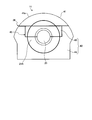
- FIG. 5 is a cross-sectional view of an external casing representing a casing structure of a steam turbine according to a third embodiment of the present invention when viewed from a direction perpendicular to the axial direction
- FIG. 6 is a cross-sectional view taken along the line AA in FIG. FIG.
- symbol is attached
- the end plate cone portion 21A is further provided on the first dividing surface 35 that divides the outer casing 11 into an upper casing 51 and a lower casing 52 on a horizontal plane through which the rotor 13 passes. Is divided.
- the outer casing 11 is divided into an upper casing 51 and a lower casing 52 on the horizontal plane through which the rotor 13 passes, and the upper casing 51 is divided. Is divided into an end plate cone upper portion 21A-1 of the end plate cone portion 21A and an upper block 53 having a top plate 31a, and a lower casing 52 is divided into an end plate cone lower portion 21A-2 of the end plate cone portion 21A and It is divided into a lower block 54 other than the part.
- Reference numeral 51 a is a top plate of the upper compartment 51.
- the end plate cone portion 21A has an L-shaped joining portion 56 of the outer peripheral portion 55. That is, at the joint portion 56 between the end plate cone portion 21A and the upper block 53 (lower block 54) of the external casing 11, the joint portion 21a of the end plate cone portion 21A is formed in an L shape, and the upper block 53 (lower block 54). ) And the joint portion 53a (54a).
- the joint portion 56 of the outer peripheral portion 55 of the end plate cone portion 21A By making the joint portion 56 of the outer peripheral portion 55 of the end plate cone portion 21A into an L shape, the distal end portion of the joint portion 21a of the end plate cone portion 21A becomes the joint portion 53a (54a) of the upper block 53 (lower block 54). And plane joining. Accordingly, a flat joint between the joint portion 21a of the end plate cone portion 21A and the joint portion 53a (54a) of the upper block 53 (lower block 54) is possible, and the joint surface of the bolt 57 can be flattened. Performance can be improved.
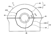
- FIG. 7 is a cross-sectional view of an external casing representing a casing structure of a steam turbine according to a fourth embodiment of the present invention when viewed from a direction perpendicular to the axial direction
- FIG. 8 is a cross-sectional view taken along line AA in FIG. FIG.
- symbol is attached
- the end plate cone section 21B having a polygonal shape around the outer shape of the end plate cone section 21A in the casing structure of the steam turbine according to the third embodiment is used.
- the outer shape of the end plate cone portion is a modified ellipsoid.
- the present invention is not limited to this.
- the outer casing 11 is divided into an upper casing 61 and a lower casing 62 on the horizontal plane through which the rotor 13 passes.
- the lower casing 62 is divided into the lower end plate cone portion 21B-2 of the end plate cone portion 21B and the lower casing 62B.
- Reference numeral 61 a is a top plate of the upper compartment 61.
- the peripheral shape of the outer shape of the end plate cone portion 21B By making the peripheral shape of the outer shape of the end plate cone portion 21B into a polygonal shape, as shown in FIG. 8, in the joint portion 66 between the outer peripheral portion 65 of the end plate cone portion 21B and the upper block 63 (lower block 64).
- the bolt joint surface can be flat. That is, at the joint 66 between the end plate cone portion 21B and the upper block 63 (lower block 64), the joint portion 21a of the end plate cone portion 21B and the joint portion 63a (64a) of the upper block 53 (lower block 54) are connected. Planar bonding is possible.
- the joint portion 21a of the end plate cone portion 21B and the joint portion 63a (64a) of the upper block 63 (lower block 64) are formed. Since the flat joint is possible and the bolt joint surface can be made flat, the sealing performance can be improved.
- FIG. 9 is a cross-sectional view of an external casing representing a casing structure of a steam turbine according to a fifth embodiment of the present invention when viewed from a direction perpendicular to the axial direction, and is a combination of upper blocks.
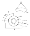
- FIG. 10 is an exploded view of a part of the upper block.
- symbol is attached
- the upper block is divided into right and left parts on the vertical plane from the center of the through hole, and is divided into two upper blocks.
- the upper block 63 divides the upper block 63 from the center of the through-hole 20 to the right and left sides, and is divided into upper blocks 63-1, 63-2.
- the upper block 63 is a vertical plane through which the rotor 13 passes, and the upper block 63-1 and the upper block 63-2 are divided by a fourth dividing surface 68.
- the upper block 63 by disassembling the upper block 63 to the left and right, the height of the upper block 63 becomes lower than before, and the upper block 63 is simply moved in the horizontal direction without moving the upper blocks 63-1, 63-2. -1, 63-2 can be divided. For this reason, since it is not necessary to increase the height of the building, the upper blocks 63-1 and 63-2 can be disassembled without changing the height of the local building.
- the present invention is not limited to this. As shown in FIG. 11, even when the external casing 11 having the end plate cone portion 21A as shown in FIG.
- the hole 20 may be divided into left and right parts from the center of the hole 20 to be divided into upper blocks 53-1 and 53-2.
- the casing structure of the steam turbine according to the present invention facilitates disassembly and transportation of the casing, and performs machining of the bellows mounting portion with current equipment, and is applicable to any type of steam turbine. Can do.
Landscapes
- Engineering & Computer Science (AREA)
- Mechanical Engineering (AREA)
- General Engineering & Computer Science (AREA)
- Turbine Rotor Nozzle Sealing (AREA)
Abstract
実施例1の蒸気タービンは、外部車室11がロータが通る水平面で上部車室31と下部車室(下ブロック)32とに分割されると共に、上部車室31が貫通孔20を有する中ブロック33と天板31aを有する上ブロック34とに分割され、ロータの通る貫通孔20が少なくとも一部含まれている部分とそれ以外の部分とに分割されてなる。これにより、上ブロック34を組むことなく下ブロック32と中ブロック33とを組んだ状態で、工場などの現状設備内で端板コーン部21Aに設けられているベローズ取付部の機械加工を行うことができる。
Description
本発明は、蒸気を用いてロータを回転駆動することで発電を行う蒸気タービンの車室構造に関するものである。
一般的な蒸気タービンにおいては、外部車室内に内部車室が設けられると共に、上部に蒸気入口部が設けられ、中心部にロータが回転自在に支持され、このロータに動翼が複数段にわたって固定される一方、内部車室に支持された翼環リングに静翼が複数段にわたって固定され、ロータに固定された動翼と交互に配設されている。
従って、蒸気タービンの運転時に、蒸気が蒸気入口部から内部車室に入ると、この蒸気は隔壁を介して翼環リングに支持された静翼を経て動翼に噴出することでロータが回転し、このロータに連結された発電機を駆動する。
この蒸気タービンのタービン本体を構成する車室(外部車室、内部車室)は、ロータの挿入や組立、分解作業の作業性を向上するため、ロータを通る平面で上下二つに分割され、フランジとボルトにより組み立てられる。そして、蒸気タービンが低圧タービンであるとき、外部車室の下部は復水器に連結されており、蒸気タービンの起動時には、内部車室及び外部車室を真空状態とすることで、蒸気を蒸気入口部から車室内部に吸引する(特許文献1、参照)。
このとき、外部車室は、この外部車室の天井や壁を形成する端板が内側に大きく凹むように変形することから、この天井や壁を補強する必要がある。蒸気タービンにおける外部車室の補強構造としては、例えば、外部車室の端板にロータ軸を中心に均等に分配されて複数のリブを溶接等により接合すると共に、外部車室の下半部の端板に複数のリブを格子状に交差して溶接等により接合するものがある。また、外部車室の内部に、パイプステーを架設するものがある(特許文献2、参照)。
このような蒸気タービンの車室構造では、外部車室の上半部の端板にI型リブをロータ軸を中心に放射状に複数本配置すると共に、その配置角度を垂直から水平になるにつれて漸次増大させている。
ここで、発電機の発電効率を上げるために蒸気タービンの大型化が望まれており、蒸気タービンを大型化すると、動翼及び静翼の長さが長くなることから、外部車室も大型化する必要がある。
しかしながら、従来の蒸気タービンの車室構造では、組立てた状態でベローズを取り付けるベローズ取付部の軸方向ズレを機械加工で平面に仕上げる必要があるため、外部車室が大きくなると、上下一体に組み上げた状態でベローズ取付部の機械加工を行うことができない、という問題がある。
また、大型化した外部車室を上下一体に組み立てたり、定期検査時などに外部車室の上部を吊り上げるためには、建屋の高さを高くする必要があるため、外部車室を上下一体に組み立てたり、外部車室の上部を吊り上げることができない、という問題がある。
また、外部車室を上下一体に組み立てベローズ取付部の機械加工を行ったとしても、車室を上下一体に組み立てた状態で工場から搬送することができない、という問題がある。
また、外部車室を立てた状態で機械加工を行うため、横型の加工機械で加工する必要があるが、ベローズ取付部の位置が高いと加工精度を維持することが困難である、という問題がある。
更に、大型化する外部車室では加工用のテーブルに収まらないため、外部車室を横置きにした状態で機械加工を行うことができない、という問題がある。
本発明は、前記問題に鑑み、現状の設備でベローズ取付部の機械加工を行うことを可能とする蒸気タービンの車室構造を提供することを目的とする。
上述した課題を解決するための本発明の第1の発明は、外部車室を上下に分割する蒸気タービンの車室構造において、前記外部車室を上部車室と下部車室とに分割すると共に、分割された前記上部車室、前記下部車室の何れか一方又は両方を、ロータの通る貫通孔が少なくとも一部含まれている部分とそれ以外の部分とに分割することを特徴とする蒸気タービンの車室構造にある。
第2の発明は、第1の発明において、前記外部車室がロータが通る水平面で上部車室と下部車室とに分割され、前記上部車室が、前記貫通孔を有する中ブロックと、天板を有する上ブロックとに分割されてなることを特徴とする蒸気タービンの車室構造にある。
第3の発明は、第1の発明において、前記外部車室が天板を有する上部車室と前記貫通孔を有する下部車室とに分割され、前記下部車室が、前記貫通孔の中心から水平方向に端板コーン部を含んで切り出される中ピースと、前記端板コーン部を含む残りの下ブロックとに分割されてなることを特徴とする蒸気タービンの車室構造にある。
第4の発明は、第1の発明において、前記外部車室がロータが通る水平面で上部車室と下部車室とに分割され、前記上部車室が、端板コーン部の端板コーン上部と、天板を有する上ブロックとに分割されると共に、前記下部車室が、前記端板コーン部の端板コーン下部と、それ以外の部分の下ブロックとに分割されてなることを特徴とする蒸気タービンの車室構造にある。
第5の発明は、第4の発明において、前記端板コーン部の外周部の接合部をL字状としてなることを特徴とする蒸気タービンの車室構造にある。
第6の発明は、第4又は5の発明において、前記端板コーン部の外形の周囲の形状を多角形状とすることを特徴とする蒸気タービンの車室構造にある。
第7の発明は、第4乃至6の何れか一つの発明において、前記上ブロックを前記貫通孔の中心から垂直面で左右に分割することを特徴とする蒸気タービンの車室構造にある。
請求項1の発明の蒸気タービンの車室構造によれば、外部車室を上部車室と下部車室とに分割すると共に、分割された前記上部車室、前記下部車室の何れか一方又は両方を、ロータの通る貫通孔が少なくとも一部含まれている部分とそれ以外の部分とに分割するので、前記上部車室を組み合わせない状態で、工場などの現状設備内でベローズ取付部の機械加工を行うことができる。
また、定期検査時には、前記上部車室のみを取外すことでロータの取替えを行うことができる。また、前記上部車室の高さは従来よりも低くなるので建屋の高さを高くする必要がないため、現地の建屋の高さを変更することなく前記上部車室を分解することができる。
請求項2の発明の蒸気タービンの車室構造によれば、前記外部車室がロータが通る水平面で上部車室と下部車室とに分割され、前記上部車室が、前記貫通孔を有する中ブロックと、天板を有する上ブロックとに分割されてなるので、前記上ブロックを組むことなく下部車室(下ブロック)と中ブロックとを組んだ状態で、工場などの現状設備内で端板コーン部に設けられているベローズ取付部の機械加工を行うことができる。
また、定期検査時には、前記上ブロックのみを取外すことでロータの取替えを行うことができる。また、前記上ブロックの高さは従来よりも低くなるので建屋の高さを高くする必要がないため、現地の建屋の高さを変更することなく前記上ブロックを分解することができる。
請求項3の発明の蒸気タービンの車室構造によれば、前記外部車室が天板を有する上部車室と前記貫通孔を有する下部車室とに分割され、前記下部車室が、前記貫通孔の中心から水平方向に端板コーン部を含んで切り出される中ピースと、前記端板コーン部を含む残りの下ブロックとに分割されてなるので、前記上部車室(上ブロック)の無い状態で、前記下ブロックと前記中ピースとを組んだ状態で、工場などの現状設備内で端板コーン部に設けられているベローズ取付部の機械加工を行うことができる。
また、前記中ピースとすることで重量を小さくすることができると共に、前記上ブロックと前記下ブロックとの接合面のボルト本数を減少させることができるため、組立作業の作業性を向上することができる。
請求項4の発明の蒸気タービンの車室構造によれば、前記外部車室がロータが通る水平面で上部車室と下部車室とに分割され、前記上部車室が、端板コーン部の端板コーン上部と、天板を有する上ブロックとに分割されると共に、前記下部車室が、前記端板コーン部の端板コーン下部と、それ以外の部分の下ブロックとに分割されてなるので、前記端板コーン上部と前記端板コーン下部を接合して前記端板コーン部のみを横置きにして工場などの現状設備内でベローズ取付部のあるベローズ取付面の機械加工を行うことができるため、工場などの現状設備内でベローズ取付面の機械加工を行うことができると共に、機械加工の精度を向上させることができる。
請求項5の発明の蒸気タービンの車室構造によれば、前記端板コーン部の外周部の接合部をL字状としてなるので、前記端板コーン部の前記外部車室との接合部における継手部がL字形状であり、前記接合部が前記外部車室と縦継手となるように形成されているので、平面継手が可能であり、ボルトの継手面を平面にすることができるため、シール性能を向上させることができる。
請求項6の発明の蒸気タービンの車室構造によれば、前記端板コーン部の外形の周囲の形状を多角形状とするので、ボルト継手面を平面にすることができるため、シール性能を向上させることができる。
請求項7の発明の蒸気タービンの車室構造によれば、前記上ブロックを前記貫通孔の中心から垂直面で左右に分割するので、前記上ブロックの高さは従来よりも更に低くなり、分解した前記上部車室をそのまま横方向に移動するたけで前記上部車室を分割することができる。このため、建屋の高さを高くする必要がないため、現地の建屋の高さを変更することなく前記上ブロックを分解することができる。
10 蒸気タービン
11 外部車室
12 蒸気入口部
13 タービンロータ(「ロータ」)
14 軸受
15 基礎台
16 軸受台
17 グランド部
18 連結部
19 ベローズ
20 貫通孔
21a 継手部分
21A、21B 端板コーン部
21A-1、21B-1 端板コーン上部
21A-2、21B-2 端板コーン下部
22 ベローズ取付部
31、41、51 上部車室
31a、41a、51a、61a 天板
31b 端板
31c フランジ部
32、42、52 下部車室
44、54 下ブロック
32a 端板
32b フランジ部
33 中ブロック
34、53 上ブロック
35 第一の分割面
36 第二の分割面
43 中ピース
45 第三の分割面
53a、54a、63a、64a 継手部分
55、65 外周部
56、66 接合部
57、67 ボルト
68 第四の分割面
以下に添付図面を参照して、本発明に係るシール部材の好適な実施例を詳細に説明する。なお、この実施例により本発明が限定されるものではない。また、下記実施例における構成要素には、当業者が容易に想定できるもの、あるいは実質的に同一のものが含まれる。
図1は、本発明の実施例1に係る蒸気タービンの車室構造が適用された蒸気タービンの概略構成図、図2は、本発明の実施例1に係る蒸気タービンの車室構造を表す外部車室の斜視図、図3は、本発明の実施例1に係る蒸気タービンの車室構造を表す外部車室を軸方向に対して垂直方向から見たときの断面図である。
実施例1の蒸気タービン10は、図1に示すように、外部車室11の上部に蒸気入口部12が設けられ、回転体であるタービンロータ(以下、「ロータ」という)13を回転自在に支持する軸受14によって支持し、軸受14を蒸気タービン10のコンクリート等からなる基礎台15の上に設けられる軸受台16で支持している。また、グランド部17は軸受台16とその連結部18とにより支持している。また、グランド部17と車室11との間には蒸気のリークを防止するベローズ19が用いられている。
また、ベローズ19は外部車室11のロータ13が通る貫通孔20で外部車室11の端板コーン部21Aのベローズ取付部22の機械加工面にボルトにより取り付けられている。
本実施例においては、外部車室11は、上部車室と下部車室とに分割されると共に、ロータ13の通る貫通孔20が少なくとも一部含まれている部分とそれ以外の部分とに分割されてなるものである。
即ち、図2、3に示すように、外部車室11がロータ13が通る水平面で上部車室31と下部車室(下ブロック)32とに分割され、上部車室31を貫通孔20を有する中ブロック33と天板31aを有する上ブロック34とに分割されている。
本実施例においては、外部車室11はロータ13が通る水平面で上部車室31と下ブロック室32とを第一の分割面35により分割される。また、上部車室31は貫通孔20を有する中ブロック33と天板31aを有する上ブロック34とに第二の分割面36により分割される。
また、上部車室31は、湾曲形状をなす天板31aと前後の端板31bにより構成され、下部にフランジ部31cが一体に形成されている。
また、下部車室32は、前後左右の端板32aにより構成され、上部にフランジ部32bが一体に形成されている。
そして、上部車室31と下部車室32は、各フランジ部31c、32bが図示しない締結ボルトにより連結される一方、下部車室32の下端部が図示しない基礎部に嵌合し、図示しない復水器に連結されている。
また、外部車室11の上部車室31の端板31bに補強リブ37を貫通孔20を中心に放射状に複数本配置している。
また、外部車室11の上部車室31の端板31bに補強リブ37を貫通孔20を中心に放射状に複数本配置している。
また、上ブロック34、中ブロック33、下ブロック32は各々分割して構成されており、例えば上ブロック34、中ブロック33、下ブロック32は各々3分割される。この各々のブロックが分割される数は特にこれに限定されるものではない。
よって、実施例1の蒸気タービンの車室構造によれば、外部車室11がロータ13が通る水平面で上部車室31と下部車室32とに分割され、上部車室31が貫通孔20を有する中ブロック33と天板31aを有する上ブロック34とに分割されている。このため、上ブロック34を組むことなく下ブロック32と中ブロック33とを組んだ状態で、工場などの現状設備内で端板コーン部21Aに設けられているベローズ取付部22の機械加工を行うことができる。
また、定期検査時には、上ブロック34のみを取外すことでロータ13の取替えを行うことができる。また、上ブロック34の高さは従来よりも低くなるので建屋の高さを高くする必要がないため、現地の従来の建屋の高さを変更することなく上ブロック34を分解することができる。
図4は、本発明の実施例2に係る蒸気タービンの車室構造を表す外部車室を軸方向に対して垂直方向から見たときの断面図である。
なお、前述した実施例で説明したものと同様の機能を有する部材には同一の符号を付して重複する説明は省略する。また、蒸気タービンの全体の説明については省略し、外部車室の構成についてのみ説明する。
なお、前述した実施例で説明したものと同様の機能を有する部材には同一の符号を付して重複する説明は省略する。また、蒸気タービンの全体の説明については省略し、外部車室の構成についてのみ説明する。
本実施例の蒸気タービンの車室構造において、図4に示すように、外部車室11が天板31aを有する上部車室(上ブロック)41と貫通孔20を有する下部車室42とに分割され、下部車室42を貫通孔20の中心から水平方向に端板コーン部21Aを含んで切り出される中ピース43と、端板コーン部21Aを含む残りの下ブロック44とに分割されている。尚、符号41aは上部車室41の天板である。
本実施例においては、外部車室11はロータ13が通る水平面で上ブロック41と下部車室42とを第二の分割面36により分割される。また、下部車室42は貫通孔20の中心から水平方向に端板コーン部21Aを含んで切り出される中ピース43と、端板コーン部21Aを含む残りの下ブロック44とに第三の分割面45により分割される。
また、上ブロック41、中ピース43は各々分割して構成されており、例えば上ブロック41は3分割され、中ピース43は4分割される。この上ブロック41、中ピース43の各々の分割される数は特にこれに限定されるものではない。
よって、上ブロック41の無い状態で、下ブロック44と中ピース43とを組んだ状態で、工場などの現状設備内で端板コーン部21Aに設けられているベローズ取付部22の機械加工を行うことができる。
また、中ピース43とすることで実施例1の中ブロック33とする場合に比べて重量を小さくすることができると共に、上ブロック41と下ブロック44との接合面のボルト本数を減少させることができるため、組立作業の作業性を向上することができる。
図5は、本発明の実施例3に係る蒸気タービンの車室構造を表す外部車室を軸方向に対して垂直方向から見たときの断面図、図6は、図5のA-A断面図である。
なお、前述した実施例で説明したものと同様の機能を有する部材には同一の符号を付して重複する説明は省略する。また、蒸気タービンの全体の説明については省略し、外部車室の構成についてのみ説明する。
なお、前述した実施例で説明したものと同様の機能を有する部材には同一の符号を付して重複する説明は省略する。また、蒸気タービンの全体の説明については省略し、外部車室の構成についてのみ説明する。
実施例3の蒸気タービンの車室構造において、外部車室11をロータ13が通る水平面で上部車室51と下部車室52とに分割する第一の分割面35に、更に端板コーン部21Aを分割するようにしたものである。
即ち、実施例3の蒸気タービンの車室構造において、図5に示すように、外部車室11がロータ13が通る水平面で上部車室51と下部車室52とに分割され、上部車室51が端板コーン部21Aの端板コーン上部21A-1と天板31aを有する上ブロック53とに分割されると共に、下部車室52を端板コーン部21Aの端板コーン下部21A-2とそれ以外の部分の下ブロック54とに分割されている。尚、符号51aは上部車室51の天板である。
よって、端板コーン部21Aのみを横置きにして工場などの現状設備内でベローズ取付部22の機械加工を行うことができるため、工場などの現状設備内でベローズ取付面の機械加工を行うことができると共に、機械加工の精度を向上させることができる。
また、図6に示すように、端板コーン部21Aは外周部55の接合部56をL字状としている。即ち、端板コーン部21Aと外部車室11の上ブロック53(下ブロック54)との接合部56では、端板コーン部21Aの継手部分21aをL字形状とし、上ブロック53(下ブロック54)の継手部分53a(54a)と縦継手となるように形成されている。
端板コーン部21Aの外周部55の接合部56をL字状とすることで、端板コーン部21Aの継手部分21aの先端部が上ブロック53(下ブロック54)の継手部分53a(54a)と平面接合することになる。よって、端板コーン部21Aの継手部分21aと上ブロック53(下ブロック54)の継手部分53a(54a)との平面継手が可能となり、ボルト57の継手面を平面にすることができるため、シール性能を向上させることができる。
図7は、本発明の実施例4に係る蒸気タービンの車室構造を表す外部車室を軸方向に対して垂直方向から見たときの断面図、図8は、図7のA-A断面図である。
なお、前述した実施例で説明したものと同様の機能を有する部材には同一の符号を付して重複する説明は省略する。また、蒸気タービンの全体の説明については省略し、外部車室の構成についてのみ説明する。
なお、前述した実施例で説明したものと同様の機能を有する部材には同一の符号を付して重複する説明は省略する。また、蒸気タービンの全体の説明については省略し、外部車室の構成についてのみ説明する。
実施例4の蒸気タービンの車室構造において、実施例3の蒸気タービンの車室構造における端板コーン部21Aの外形の周囲の形状を多角形状とした端板コーン部21Bを用いたものである。本実施例では、端板コーン部の外形を変形の11角形としている。但し、本発明はこれに限定されるものではない。
即ち、実施例4の蒸気タービンの車室構造において、図7に示すように、外部車室11がロータ13が通る水平面で上部車室61と下部車室62とに分割され、上部車室61が端板コーン部21Bの端板コーン上部21B-1と天板31aを有する上ブロック63とに分割されると共に、下部車室62を端板コーン部21Bの端板コーン下部21B-2とそれ以外の部分の下ブロック64とに分割されている。尚、符号61aは上部車室61の天板である。
端板コーン部21Bの外形の周囲の形状を多角形状とすることで、図8に示すように、端板コーン部21Bの外周部65と上ブロック63(下ブロック64)との接合部66におけるボルト継手面を平面にすることができる。即ち、端板コーン部21Bと上ブロック63(下ブロック64)との接合部66では、端板コーン部21Bの継手部分21aと上ブロック53(下ブロック54)の継手部分63a(64a)とを平面接合することができる。
よって、端板コーン部21Bのように外形の周囲の形状を多角形状とすることで、端板コーン部21Bの継手部分21aと上ブロック63(下ブロック64)の継手部分63a(64a)とが平面接合し、ボルト継手面を平面にすることができるため、シール性能を向上させることができる。
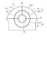
図9は、本発明の実施例5に係る蒸気タービンの車室構造を表す外部車室を軸方向に対して垂直方向から見たときの断面図であり、上ブロックを組み合わせたものである。図10は、上ブロックの一部を分解した図である。
なお、前述した実施例で説明したものと同様の機能を有する部材には同一の符号を付して重複する説明は省略する。また、蒸気タービンの全体の説明については省略し、外部車室の構成についてのみ説明する。
なお、前述した実施例で説明したものと同様の機能を有する部材には同一の符号を付して重複する説明は省略する。また、蒸気タービンの全体の説明については省略し、外部車室の構成についてのみ説明する。
実施例5の蒸気タービンの車室構造において、上ブロックを貫通孔の中心から垂直面で左右に分割し、2つの上ブロックに分解している。
即ち、図9、10に示すように、上ブロック63は上ブロック63を貫通孔20の中心から垂直面に左右に分割し、上ブロック63-1、63-2に分解している。
本実施例においては、上ブロック63はロータ13が通る垂直面で上ブロック63-1と上ブロック63-2とを第四の分割面68により分割される。
よって、上ブロック63を左右に分解することで、上ブロック63の高さは従来よりも更に低くなり、分解した上ブロック63-1、63-2をそのまま横方向に移動するたけで上ブロック63-1、63-2を分割することができる。このため、建屋の高さを高くする必要がないため、現地の建屋の高さを変更することなく上ブロック63-1、63-2を分解することができる。
また、本発明はこれに限定されるものではなく、図11に示すように、図5に示すような端板コーン部21Aを有する外部車室11を用いた場合でも同様に上ブロック51を貫通孔20の中心から垂直面に左右に分割し、上ブロック53-1、53-2に分解するようにしてもよい。
本発明に係る蒸気タービンの車室構造は、車室の分解、運搬を容易に行い、現状の設備でベローズ取付部の機械加工を行うものであり、いずれの種類の蒸気タービンにも適用することができる。
Claims (7)
- 外部車室を上下に分割する蒸気タービンの車室構造において、
前記外部車室を上部車室と下部車室とに分割すると共に、
分割された前記上部車室、前記下部車室の何れか一方又は両方を、ロータの通る貫通孔が少なくとも一部含まれている部分とそれ以外の部分とに分割することを特徴とする蒸気タービンの車室構造。 - 請求項1において、
前記外部車室がロータが通る水平面で上部車室と下部車室とに分割され、
前記上部車室が、前記貫通孔を有する中ブロックと、天板を有する上ブロックとに分割されてなることを特徴とする蒸気タービンの車室構造。 - 請求項1において、
前記外部車室が天板を有する上部車室と前記貫通孔を有する下部車室とに分割され、
前記下部車室が、前記貫通孔の中心から水平方向に端板コーン部を含んで切り出される中ピースと、前記端板コーン部を含む残りの下ブロックとに分割されてなることを特徴とする蒸気タービンの車室構造。 - 請求項1において、
前記外部車室がロータが通る水平面で上部車室と下部車室とに分割され、
前記上部車室が、端板コーン部の端板コーン上部と、天板を有する上ブロックとに分割されると共に、
前記下部車室が、前記端板コーン部の端板コーン下部と、それ以外の部分の下ブロックとに分割されてなることを特徴とする蒸気タービンの車室構造。 - 請求項4において、
前記端板コーン部の外周部の接合部をL字状としてなることを特徴とする蒸気タービンの車室構造。 - 請求項4又は5において、
前記端板コーン部の外形の周囲の形状を多角形状とすることを特徴とする蒸気タービンの車室構造。 - 請求項4乃至6の何れか一つにおいて、
前記上ブロックを前記貫通孔の中心から垂直面で左右に分割することを特徴とする蒸気タービンの車室構造。
Priority Applications (4)
| Application Number | Priority Date | Filing Date | Title |
|---|---|---|---|
| EP09728296.6A EP2305962B1 (en) | 2008-03-31 | 2009-03-12 | Casing for a gas turbine |
| CN200980111129.7A CN101981279B (zh) | 2008-03-31 | 2009-03-12 | 蒸汽轮机的机室构造 |
| US12/918,865 US8777565B2 (en) | 2008-03-31 | 2009-03-12 | Casing structure of steam turbine |
| ZA2010/06064A ZA201006064B (en) | 2008-03-31 | 2010-08-25 | Compartment structure for steam turbine |
Applications Claiming Priority (2)
| Application Number | Priority Date | Filing Date | Title |
|---|---|---|---|
| JP2008093346A JP5180652B2 (ja) | 2008-03-31 | 2008-03-31 | 蒸気タービンの車室構造 |
| JP2008-093346 | 2008-03-31 |
Publications (1)
| Publication Number | Publication Date |
|---|---|
| WO2009122879A1 true WO2009122879A1 (ja) | 2009-10-08 |
Family
ID=41135265
Family Applications (1)
| Application Number | Title | Priority Date | Filing Date |
|---|---|---|---|
| PCT/JP2009/054764 Ceased WO2009122879A1 (ja) | 2008-03-31 | 2009-03-12 | 蒸気タービンの車室構造 |
Country Status (6)
| Country | Link |
|---|---|
| US (1) | US8777565B2 (ja) |
| EP (1) | EP2305962B1 (ja) |
| JP (1) | JP5180652B2 (ja) |
| CN (1) | CN101981279B (ja) |
| WO (1) | WO2009122879A1 (ja) |
| ZA (1) | ZA201006064B (ja) |
Cited By (1)
| Publication number | Priority date | Publication date | Assignee | Title |
|---|---|---|---|---|
| CN102656340A (zh) * | 2009-12-08 | 2012-09-05 | 西门子公司 | 用于汽轮机的多件式内壳体 |
Families Citing this family (13)
| Publication number | Priority date | Publication date | Assignee | Title |
|---|---|---|---|---|
| EP2372111A1 (en) * | 2010-03-27 | 2011-10-05 | Alstom Technology Ltd | Low pressure turbine with two independent condensing systems |
| US8662821B2 (en) * | 2010-12-29 | 2014-03-04 | General Electric Company | Removable steam inlet assembly for steam turbine |
| JP5730073B2 (ja) * | 2011-02-28 | 2015-06-03 | 三菱重工業株式会社 | タービンの車室構造及びタービンの車室の内部部材取り出し方法 |
| JP5524411B2 (ja) * | 2011-03-31 | 2014-06-18 | 三菱重工業株式会社 | 蒸気タービンの車室位置調整装置 |
| KR101861318B1 (ko) * | 2011-06-09 | 2018-05-28 | 삼성전자주식회사 | 터치 스크린을 구비한 기기의 인터페이스 제공 장치 및 방법 |
| US9194246B2 (en) | 2011-09-23 | 2015-11-24 | General Electric Company | Steam turbine LP casing cylindrical struts between stages |
| US9279342B2 (en) * | 2012-11-21 | 2016-03-08 | General Electric Company | Turbine casing with service wedge |
| US9260281B2 (en) * | 2013-03-13 | 2016-02-16 | General Electric Company | Lift efficiency improvement mechanism for turbine casing service wedge |
| JP6204727B2 (ja) * | 2013-07-10 | 2017-09-27 | 三菱日立パワーシステムズ株式会社 | 蒸気タービンの低圧排気室 |
| DE102015213257A1 (de) * | 2015-07-15 | 2017-01-19 | Siemens Aktiengesellschaft | Abdampfgehäuse für eine Turbine, Turbinengestell, Turbinengehäuse und Montagesystem |
| JP6884660B2 (ja) * | 2017-07-13 | 2021-06-09 | 三菱パワー株式会社 | 蒸気タービンシステム |
| US11536291B2 (en) * | 2020-02-04 | 2022-12-27 | Mitsubishi Heavy Industries Compressor Corporation | Rotor hanging tool, rotor support jig, rotor lifting method, and rotary machine disassembly method |
| WO2025183270A1 (ko) * | 2024-02-27 | 2025-09-04 | 한국수력원자력 주식회사 | 발전소의 저압터빈을 위한 모듈형 케이싱 |
Citations (7)
| Publication number | Priority date | Publication date | Assignee | Title |
|---|---|---|---|---|
| US3520634A (en) * | 1966-12-02 | 1970-07-14 | Bbc Brown Boveri & Cie | Exhaust steam housing for low pressure steam turbines |
| JPS4839804A (ja) * | 1971-09-23 | 1973-06-12 | ||
| JPS4981702A (ja) * | 1972-11-28 | 1974-08-07 | ||
| US3942907A (en) * | 1974-04-02 | 1976-03-09 | Bbc Brown Boveri & Company Limited | Two-shell casing for fluid flow machine |
| JPS623106A (ja) * | 1985-06-27 | 1987-01-09 | シーメンス、アクチエンゲゼルシヤフト | タ−ビンユニツト |
| JP2005113721A (ja) | 2003-10-06 | 2005-04-28 | Hitachi Ltd | 蒸気タービン |
| JP3831617B2 (ja) | 2001-02-06 | 2006-10-11 | 三菱重工業株式会社 | 蒸気タービンの車室構造 |
Family Cites Families (6)
| Publication number | Priority date | Publication date | Assignee | Title |
|---|---|---|---|---|
| US4102598A (en) * | 1975-11-11 | 1978-07-25 | Westinghouse Electric Corp. | Single case low pressure turbine |
| JPH08260904A (ja) * | 1995-03-29 | 1996-10-08 | Toshiba Corp | 蒸気タービン排気室 |
| JP3772019B2 (ja) * | 1998-04-21 | 2006-05-10 | 株式会社東芝 | 蒸気タービン |
| US6971842B2 (en) * | 2003-09-22 | 2005-12-06 | General Electric Company | Low pressure steam turbine exhaust hood |
| JP4839804B2 (ja) | 2005-11-29 | 2011-12-21 | 凸版印刷株式会社 | ボトル容器 |
| JP4981702B2 (ja) | 2008-02-04 | 2012-07-25 | 三菱重工業株式会社 | 風力発電装置 |
-
2008
- 2008-03-31 JP JP2008093346A patent/JP5180652B2/ja active Active
-
2009
- 2009-03-12 US US12/918,865 patent/US8777565B2/en active Active
- 2009-03-12 CN CN200980111129.7A patent/CN101981279B/zh active Active
- 2009-03-12 WO PCT/JP2009/054764 patent/WO2009122879A1/ja not_active Ceased
- 2009-03-12 EP EP09728296.6A patent/EP2305962B1/en active Active
-
2010
- 2010-08-25 ZA ZA2010/06064A patent/ZA201006064B/en unknown
Patent Citations (7)
| Publication number | Priority date | Publication date | Assignee | Title |
|---|---|---|---|---|
| US3520634A (en) * | 1966-12-02 | 1970-07-14 | Bbc Brown Boveri & Cie | Exhaust steam housing for low pressure steam turbines |
| JPS4839804A (ja) * | 1971-09-23 | 1973-06-12 | ||
| JPS4981702A (ja) * | 1972-11-28 | 1974-08-07 | ||
| US3942907A (en) * | 1974-04-02 | 1976-03-09 | Bbc Brown Boveri & Company Limited | Two-shell casing for fluid flow machine |
| JPS623106A (ja) * | 1985-06-27 | 1987-01-09 | シーメンス、アクチエンゲゼルシヤフト | タ−ビンユニツト |
| JP3831617B2 (ja) | 2001-02-06 | 2006-10-11 | 三菱重工業株式会社 | 蒸気タービンの車室構造 |
| JP2005113721A (ja) | 2003-10-06 | 2005-04-28 | Hitachi Ltd | 蒸気タービン |
Non-Patent Citations (1)
| Title |
|---|
| See also references of EP2305962A4 * |
Cited By (2)
| Publication number | Priority date | Publication date | Assignee | Title |
|---|---|---|---|---|
| CN102656340A (zh) * | 2009-12-08 | 2012-09-05 | 西门子公司 | 用于汽轮机的多件式内壳体 |
| EP2510196A1 (de) * | 2009-12-08 | 2012-10-17 | Siemens Aktiengesellschaft | Mehrteiliges innengehäuse für eine dampfturbine |
Also Published As
| Publication number | Publication date |
|---|---|
| EP2305962A4 (en) | 2013-03-27 |
| CN101981279A (zh) | 2011-02-23 |
| JP2009243413A (ja) | 2009-10-22 |
| CN101981279B (zh) | 2015-01-14 |
| EP2305962B1 (en) | 2016-03-09 |
| ZA201006064B (en) | 2011-10-26 |
| US20110020117A1 (en) | 2011-01-27 |
| US8777565B2 (en) | 2014-07-15 |
| JP5180652B2 (ja) | 2013-04-10 |
| EP2305962A1 (en) | 2011-04-06 |
Similar Documents
| Publication | Publication Date | Title |
|---|---|---|
| JP5180652B2 (ja) | 蒸気タービンの車室構造 | |
| JP5323529B2 (ja) | ポンプ用吸込渦防止部材 | |
| RU2553582C2 (ru) | Паровая турбина низкого давления | |
| US20090134627A1 (en) | Arrangement for a direct drive generator for a wind turbine and method for the assembly of the generator | |
| US10465769B2 (en) | Transmission and transmission turbomachine | |
| JP6000354B2 (ja) | 軸流排気タービン | |
| US9541069B2 (en) | Nacelle shell structure, lock labyrinth and wind turbine | |
| CN110771008B (zh) | 用于风力涡轮机的发电机的支撑结构部段 | |
| CN106661961B (zh) | 具有可拆卸支柱的涡轮机组件 | |
| RU2384712C2 (ru) | Газотурбинная установка (варианты) и ее корпус | |
| US9970210B2 (en) | Combined cycle plant and plant building thereof | |
| RU2631585C2 (ru) | Направляющий аппарат компрессора для турбомашины | |
| JP5134680B2 (ja) | ガスタービン及びガスタービンの車室開放方法 | |
| US9951654B2 (en) | Stator blade sector for an axial turbomachine with a dual means of fixing | |
| US20140322007A1 (en) | Turbine diaphragm construction | |
| JP5490615B2 (ja) | 立軸渦巻ポンプ | |
| CN208142948U (zh) | 转子及风力发电机组 | |
| JP6235502B2 (ja) | 蒸気タービン設備 | |
| JP2018066303A (ja) | 蒸気タービンシステム | |
| JP6614576B2 (ja) | 車室の製造方法、及び回転機械の製造方法 | |
| JP7120913B2 (ja) | ガスタービン排気車室及びガスタービン | |
| JP2005233080A (ja) | ガスタービン | |
| JP2006312885A (ja) | 低圧蒸気タービンの構造 | |
| US9366146B2 (en) | Closure bucket for turbo-machine | |
| JP2007009820A (ja) | タービン車室 |
Legal Events
| Date | Code | Title | Description |
|---|---|---|---|
| WWE | Wipo information: entry into national phase |
Ref document number: 200980111129.7 Country of ref document: CN |
|
| 121 | Ep: the epo has been informed by wipo that ep was designated in this application |
Ref document number: 09728296 Country of ref document: EP Kind code of ref document: A1 |
|
| WWE | Wipo information: entry into national phase |
Ref document number: 12918865 Country of ref document: US |
|
| WWE | Wipo information: entry into national phase |
Ref document number: 2009728296 Country of ref document: EP |
|
| NENP | Non-entry into the national phase |
Ref country code: DE |