WO2009122971A1 - 医療用閉塞具 - Google Patents
医療用閉塞具 Download PDFInfo
- Publication number
- WO2009122971A1 WO2009122971A1 PCT/JP2009/055857 JP2009055857W WO2009122971A1 WO 2009122971 A1 WO2009122971 A1 WO 2009122971A1 JP 2009055857 W JP2009055857 W JP 2009055857W WO 2009122971 A1 WO2009122971 A1 WO 2009122971A1
- Authority
- WO
- WIPO (PCT)
- Prior art keywords
- medical obturator
- core
- medical
- swelling
- wire
- Prior art date
- Legal status (The legal status is an assumption and is not a legal conclusion. Google has not performed a legal analysis and makes no representation as to the accuracy of the status listed.)
- Ceased
Links
Images


Classifications
-
- A—HUMAN NECESSITIES
- A61—MEDICAL OR VETERINARY SCIENCE; HYGIENE
- A61B—DIAGNOSIS; SURGERY; IDENTIFICATION
- A61B17/00—Surgical instruments, devices or methods
- A61B17/12—Surgical instruments, devices or methods for ligaturing or otherwise compressing tubular parts of the body, e.g. blood vessels or umbilical cord
- A61B17/12022—Occluding by internal devices, e.g. balloons or releasable wires
- A61B17/12099—Occluding by internal devices, e.g. balloons or releasable wires characterised by the location of the occluder
- A61B17/12104—Occluding by internal devices, e.g. balloons or releasable wires characterised by the location of the occluder in an air passage
-
- A—HUMAN NECESSITIES
- A61—MEDICAL OR VETERINARY SCIENCE; HYGIENE
- A61B—DIAGNOSIS; SURGERY; IDENTIFICATION
- A61B17/00—Surgical instruments, devices or methods
- A61B17/12—Surgical instruments, devices or methods for ligaturing or otherwise compressing tubular parts of the body, e.g. blood vessels or umbilical cord
- A61B17/12022—Occluding by internal devices, e.g. balloons or releasable wires
- A61B17/12131—Occluding by internal devices, e.g. balloons or releasable wires characterised by the type of occluding device
- A61B17/1214—Coils or wires
-
- A—HUMAN NECESSITIES
- A61—MEDICAL OR VETERINARY SCIENCE; HYGIENE
- A61B—DIAGNOSIS; SURGERY; IDENTIFICATION
- A61B17/00—Surgical instruments, devices or methods
- A61B17/12—Surgical instruments, devices or methods for ligaturing or otherwise compressing tubular parts of the body, e.g. blood vessels or umbilical cord
- A61B17/12022—Occluding by internal devices, e.g. balloons or releasable wires
- A61B17/12131—Occluding by internal devices, e.g. balloons or releasable wires characterised by the type of occluding device
- A61B17/12168—Occluding by internal devices, e.g. balloons or releasable wires characterised by the type of occluding device having a mesh structure
- A61B17/12172—Occluding by internal devices, e.g. balloons or releasable wires characterised by the type of occluding device having a mesh structure having a pre-set deployed three-dimensional shape
-
- A—HUMAN NECESSITIES
- A61—MEDICAL OR VETERINARY SCIENCE; HYGIENE
- A61B—DIAGNOSIS; SURGERY; IDENTIFICATION
- A61B17/00—Surgical instruments, devices or methods
- A61B17/12—Surgical instruments, devices or methods for ligaturing or otherwise compressing tubular parts of the body, e.g. blood vessels or umbilical cord
- A61B17/12022—Occluding by internal devices, e.g. balloons or releasable wires
- A61B17/12131—Occluding by internal devices, e.g. balloons or releasable wires characterised by the type of occluding device
- A61B17/12181—Occluding by internal devices, e.g. balloons or releasable wires characterised by the type of occluding device formed by fluidized, gelatinous or cellular remodelable materials, e.g. embolic liquids, foams or extracellular matrices
- A61B17/1219—Occluding by internal devices, e.g. balloons or releasable wires characterised by the type of occluding device formed by fluidized, gelatinous or cellular remodelable materials, e.g. embolic liquids, foams or extracellular matrices expandable in contact with liquids
-
- A—HUMAN NECESSITIES
- A61—MEDICAL OR VETERINARY SCIENCE; HYGIENE
- A61B—DIAGNOSIS; SURGERY; IDENTIFICATION
- A61B17/00—Surgical instruments, devices or methods
- A61B2017/00743—Type of operation; Specification of treatment sites
- A61B2017/00809—Lung operations
-
- A—HUMAN NECESSITIES
- A61—MEDICAL OR VETERINARY SCIENCE; HYGIENE
- A61B—DIAGNOSIS; SURGERY; IDENTIFICATION
- A61B17/00—Surgical instruments, devices or methods
- A61B2017/00831—Material properties
- A61B2017/00898—Material properties expandable upon contact with fluid
-
- A—HUMAN NECESSITIES
- A61—MEDICAL OR VETERINARY SCIENCE; HYGIENE
- A61B—DIAGNOSIS; SURGERY; IDENTIFICATION
- A61B17/00—Surgical instruments, devices or methods
- A61B17/12—Surgical instruments, devices or methods for ligaturing or otherwise compressing tubular parts of the body, e.g. blood vessels or umbilical cord
- A61B17/12022—Occluding by internal devices, e.g. balloons or releasable wires
- A61B2017/1205—Introduction devices
- A61B2017/12054—Details concerning the detachment of the occluding device from the introduction device
Definitions
- the present invention relates to a medical obturator that is placed in a living body lumen and closes the living body lumen.
- Emphysema is a lesion mainly formed by extensive destruction of the peripheral airways and alveoli, mainly caused by inhalation of harmful substances such as smoking.
- the formation of the lesion is chronic progressive, and in advanced patients, respiratory function is significantly inhibited.
- the main treatment methods for patients with emphysema can be broadly divided into medical treatment and surgical treatment. Although medical treatment can alleviate the patient's symptoms, the progression of emphysema is stopped. It is difficult.
- surgical treatment includes, for example, lung volume reduction surgery and lung transplantation, both of which require large surgery, are very burdensome for the patient, and are very expensive. It is not easy to implement.
- patent document 1 has resin bronchial obstruction material (occlusion material) which makes a truncated cone shape. Is disclosed. This obturator is placed at a predetermined part of the bronchus by a bronchoscope (bronchoscope) or the like, and closes the predetermined part of the bronchus. It is set larger than the inner diameter of the (occlusion planned site).
- occlusion material resin bronchial obstruction material
- the obturator has an outer diameter larger than the inner diameter of the lumen of the bronchoscope and cannot be inserted into the lumen of the bronchoscope. For this reason, the obturator passes through the lumen of the bronchoscope, A citrus or the like protruding outward from the distal end is grasped on the distal end side of the bronchoscope and transferred to the planned bronchial occlusion site together with the bronchoscope and placed.
- such a conventional occlusion material has an outer diameter larger than the inner diameter of the bronchial planned occlusion site, is gripped with citrus on the distal end side of the bronchoscope, is transferred to the planned occlusion site, and is detained.
- the procedure requires years of experience and skill.
- the occluding material is usually placed at a plurality of locations.
- the bronchoscope is removed from the body each time, and the obturator to be placed next is externally inserted from the distal end of the bronchoscope. Therefore, it is necessary to perform an operation of inserting the bronchoscope into the body again, which increases the treatment time and the burden on the patient.
- An object of the present invention is to provide a medical obturator that can be easily, quickly and reliably placed in a living body lumen.
- the present invention provides: (1) A medical obturator that is placed in a living body lumen and closes the living body lumen,
- the core It is composed of a swellable material that swells by absorbing liquid and increases in volume, and includes a swelling part provided around the core part,
- the medical obturator is configured to be fixed in the living body lumen and to close the living body lumen by swelling the swelling portion.
- the medical obturator is transferred to the site (planned site to be occluded) of the living body lumen in a state where the swelling part is contracted (state before swelling), and then the swelling part. Since it swells (expands), it is fixed (indwelled), so that the medical obturator can be indwelled easily and quickly.
- the medical obturator is fixed in the living body lumen when the swelling portion swells and closes the living body lumen, so that the medical obturator can be securely fixed, It can be reliably occluded.
- the uneven shape can be followed, and the surface of the living tissue can be reliably adhered.
- the swelling portion of the medical obturator is in a contracted state before being placed in the living body lumen, for example, a device used when the medical obturator is placed (for example, the medical obturator) Can be transported to the distal end of the device using the lumen of a bronchoscope or the like.
- the medical obturator can be placed at a plurality of locations while the device is inserted into the body, whereby the processing time can be shortened and the burden on the patient can be reduced.
- the swellable material is preferably a gel polymer.
- the gel polymer has an anionic group in a part of its molecular structure.
- the gel polymer selectively increases in the swelling rate (expansion rate) and shrinkage rate depending on the composition of the liquid in contact and the concentration of ions contained therein.
- the environment-sensitive gel polymer selectively increases in the swelling rate (expansion rate) and shrinkage rate depending on the composition of the liquid in contact with the concentration of ions contained therein.
- the hydrophilicity of the environment-sensitive gel polymer is increased, more liquid can be actively absorbed and swollen. Since the hydrophilicity of the gel polymer is increased, more liquid can be actively absorbed and swollen.
- the gel polymer increases in volume by contact with the liquid that deprotonates the anionic group, and increases in volume by contact with the liquid that protonates the anionic group. Preferably, it can be reduced.
- the gel polymer contains at least one selected from acrylic acid, methacrylic acid and derivatives thereof as a monomer component.
- the gel polymer containing these has an anionic group, it becomes more environmentally sensitive.
- the gel polymer preferably contains an ethylenically unsaturated compound as a cross-linking agent.
- the core part is composed of a rod-shaped wire, It is preferable that the swelling portion is provided along the wire and covers the wire.
- the core portion is composed of a coiled wire material
- the swollen portion is preferably provided in a coil shape along the wire and covers the wire.
- the core portion is composed of a coiled wire material
- the swelling portion is preferably provided in a rod shape so as to cover the entire wire.
- the contact area between the core portion and the swollen portion is large, and thus the adhesion between the core portion and the swollen portion is improved.
- the core has a contrast property.
- X-ray contrast property is obtained in the core (medical obturator), and the medical obturator is placed in the bronchi while confirming (viewing) the position of the medical obturator under fluoroscopy. be able to.
- the surface of the core part is preferably roughened.
- This increases the contact area with the swollen portion and improves the adhesion with the swollen portion.
- the medical obturator of the present invention preferably closes the bronchi.
- a fixing assisting means for assisting the fixing when the swelling portion is fixed in the living body lumen is provided.
- the medical obturator can be more securely fixed to the living body lumen.
- the fixing auxiliary means is made of an elastic material, and contracts by applying an external force against the elastic force, and expands by releasing the front external force. Preferably there is.
- the medical obturator can be more securely fixed to the living body lumen.
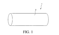
- FIG. 1 is a perspective view showing a first embodiment of the medical obturator of the present invention.
- 2 is a longitudinal sectional view showing the medical obturator shown in FIG.
- FIG. 3 is a view for explaining a method of using the medical obturator shown in FIG.
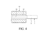
- FIG. 4 is a view for explaining a method of using the medical obturator shown in FIG.
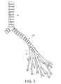
- FIG. 5 is a view for explaining a method of using the medical obturator shown in FIG.
- FIG. 6 is a side view showing a second embodiment of the medical obturator of the present invention.
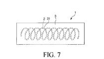
- FIG. 7 is a side view showing a third embodiment of the medical obturator of the present invention.
- FIG. 8 is a longitudinal cross-sectional view (figure for demonstrating a usage method) which shows 4th Embodiment of the medical obturator of this invention.
- the present invention can be applied to various medical obturators that are placed in a living body lumen (fixed to a living tissue that defines the living body lumen) and block the living body lumen.
- a case where the present invention is applied to a bronchial obturator (bronchial obturator) that closes (closes) the bronchi will be described as a representative example.
- FIG. 1 is a perspective view showing a first embodiment of the medical obturator of the present invention
- FIG. 2 is a longitudinal sectional view showing the medical obturator shown in FIG. 1,
- FIGS. It is a figure for demonstrating the usage method of the medical obturator shown in FIG.
- the medical obturator 1 shown in these drawings is a device that is fixed (indwelled) in the bronchus and closes the bronchi.
- the medical obturator 1 has a core part 2 and a swollen part 3 provided (fixed) around the core part 2.
- the core part 2 has a function of a reinforcing member that reinforces the swelling part 3 (medical obturator 1).
- This core part 2 is comprised by the rod-shaped wire 21, and has comprised linear form in this embodiment.
- the core part 2 may be solid, may be hollow, and may have comprised the cylinder shape.
- the surface of the core part 2 is preferably roughened. Thereby, a contact area with the swelling part 3 becomes large, and adhesiveness with the swelling part 3 improves.
- the core 2 preferably has contrast properties under fluoroscopy (including CT scan), MRI, or the like. Moreover, it is preferable that the core part 2 is comprised with the metal material.
- the metal material constituting the core portion 2 include stainless steel, superelastic alloy, cobalt-based alloy, noble metals such as gold, platinum, tungsten, and alloys containing these (for example, platinum-iridium alloy).
- X-ray opaque material such as a noble metal
- X-ray contrast can be obtained in the core 2 (medical obturator 1). It is preferable that the medical obturator 1 can be placed in the bronchus while confirming (viewing) the position of the medical obturator 1 under fluoroscopy.
- the dimensions (length, outer diameter, etc.) of the core part 2 are not particularly limited, and are appropriately determined according to the site (position) where the medical obturator 1 is placed, the case, and the like.
- the length of the core part 2 is preferably about 5 to 100 mm, more preferably about 10 to 50 mm.
- the outer diameter of the core 2 is preferably about 0.01 to 1 mm, and more preferably about 0.02 to 0.5 mm.
- the swelling part 3 is made of a swellable material that absorbs liquid and swells (expands) to increase its volume.
- the swollen portion 3 can swell at a site where the bronchus is blocked (site to be blocked) until the bronchus is blocked by being in close contact with the inner wall of the bronchus. That is, the medical obturator 1 is fixed in the bronchus when the swelling portion 3 swells and closes the bronchi.
- the description will be made in a state where the swelling portion 3 is contracted (a state before swelling).
- the swelling part 3 is provided along the wire 21 of the core 2 and covers the entire wire 21 (core 2). That is, the core part 2 is embedded in the swelling part 3.
- the swelling part 3 has a rod shape
- the medical obturator 1 has a columnar shape.
- the dimensions (length, outer diameter, etc.) of the swelling part 3 (medical obturator 1) are not particularly limited, and are appropriately determined according to the site (position) where the medical obturator 1 is placed, the case, and the like.
- the Usually, the length of the swelling part 3 (medical obturator 1) is preferably about 5 to 100 mm, more preferably about 10 to 50 mm.
- the outer diameter of the swelling part 3 (medical obturator 1) is set smaller than the inner diameter of the lumen of the bronchoscope described later. Thereby, the medical obturator 1 can move within the lumen of the bronchoscope. Moreover, the outer diameter of the swelling part 3 (medical obturator 1) is set to such an extent that the bronchus can be occluded when the swelling part 3 swells. Specifically, the outer diameter of the swelling part 3 (medical obturator 1) is preferably about 1 to 50 mm, more preferably about 5 to 30 mm.
- the swellable material constituting the swelling part 3 is not particularly limited as long as it absorbs liquid and swells to increase the volume, but a gel polymer is preferable. In the present embodiment, a case where a gel polymer is used as the swellable material will be described.
- the gel polymer (polymer) constituting the swollen portion 3 has a property that its volume changes upon contact with a liquid.
- the gel polymer does not form a gel state in a dry state (the most contracted state) before gelation, but has a property of swelling (expanding) and gelling by incorporating a liquid therein. .
- the gel polymer swollen in this manner has a property of releasing the taken-in liquid and contracting when it comes into contact with a liquid having a predetermined property.
- this gel polymer can be selected from swelling (expansion) and shrinkage depending on the nature of the liquid in contact.
- Such gel polymers are commonly referred to as “environmentally sensitive gel polymers”.
- the environmentally sensitive gel polymer is a crosslinked body obtained by polymerizing and crosslinking an environmentally sensitive monomer component or prepolymer component, and is composed of a polymer having a three-dimensional network structure.
- Such an environmentally sensitive gel polymer has pores in the gaps between the molecular chains.
- the pores expand and contract according to the bonding force between the molecular chains, but the bonding force between the molecular chains varies depending on the environment in which the gel polymer exists. Due to such properties, the environment-sensitive gel polymer can take in the liquid into the pores and discharge the taken-in liquid in accordance with the change in the environment.
- Examples of the monomer component or prepolymer component of the environmentally sensitive gel polymer include acrylic acid, methacrylic acid, or derivatives thereof, styrene sulfonic acid, vinyl sulfonic acid, vinyl phosphoric acid, and the like, one or two of these. Mixtures of more than one species can be used.
- Acrylic acid, methacrylic acid, or derivatives thereof are particularly preferably used.
- Acrylic acid, methacrylic acid, or derivatives thereof are environmentally sensitive monomer components (prepolymer components), and the gel polymer containing them has an ionic functional group, which will be described later. It will be a thing.
- the monomer component or prepolymer component of the environmentally sensitive gel polymer may be ethylenically unsaturated such as 2-hydroxyethyl acrylate, 2-hydroxyethyl methacrylate, acrylamide or methacrylamide, or derivatives thereof. Preferably it contains monomers.
- acrylamide is particularly preferably used.
- the mechanical properties of the gel polymer can be enhanced.
- the monomer component or the prepolymer component has an ionic functional group in a part of its molecular structure.
- the environment-sensitive gel polymer selectively increases in swelling rate (expansion rate) and shrinkage rate depending on the composition of the liquid in contact with the concentration of ions contained, and the like.
- swelling rate expansion rate
- shrinkage rate shrinkage rate depending on the composition of the liquid in contact with the concentration of ions contained, and the like.
- hydrophilicity of the environment-sensitive gel polymer is increased, more liquid can be actively absorbed and swollen.
- This ionic functional group is an anionic group
- an environmentally sensitive gel polymer containing such an ionic functional group swells by deprotonation and increases in volume.
- the swollen environment-sensitive gel polymer contracts by protonation and decreases in volume. Therefore, an environmentally sensitive gel polymer containing an anionic group swells by contact with a liquid exhibiting a deprotonation action, and then contracts by contacting with a liquid exhibiting a protonation action.
- the environment-sensitive gel polymer containing an anionic group has the smallest volume in the dry state (the most contracted state) before gelation, and in the gel state in contact with the liquid, the pH of the liquid in contact is low. The larger, the greater the swelling rate and the larger the volume.
- the volume of the environmentally sensitive gel polymer containing an anionic group has a positive correlation with the pH of the liquid in contact with the gel polymer.
- anionic group examples include a carboxylic acid group, a mercapto group, a phosphoric acid group, and a sulfonic acid group.
- the ionic functional group may be a cationic group.
- the environment-sensitive gel polymer swells when protonated, and the volume increases.
- the swollen environment-sensitive gel polymer contracts by deprotonation and decreases in volume. Therefore, an environmentally sensitive gel polymer containing a cationic group swells by contact with a liquid having a protonation effect and then contracts by contact with a liquid having a deprotonation effect.
- the environment-sensitive gel polymer containing a cationic group has the smallest volume in the dry state (the most contracted state) before gelation, and in the gel state in contact with the liquid, the pH of the liquid in contact is low. The smaller, the greater the swelling rate and the larger the volume. Thus, the volume of the environmentally sensitive gel polymer containing a cationic group has a negative correlation with the pH of the liquid in contact with the gel polymer.
- Examples of the cationic group include an amino group and an ammonium base.
- the ionic functional group is an anionic group will be described as a representative.
- the swellable material constituting the swelling portion 3 is not limited to a gel polymer, and may be, for example, a material that swells by incorporating a liquid therein but does not gel.
- the content of the environmentally sensitive monomer component in all the monomer components is preferably about 10 to 50% by mass, and more preferably about 10 to 30% by mass.
- the content of the monomer component in the solution is not particularly limited, but is preferably about 20 to 30% by mass.
- crosslinking agent examples include N, N′-methylenebisacrylamide, ethylene glycol di (meth) acrylate, diethylene glycol di (meth) acrylate, triethylene glycol di (meth) acrylate, polyethylene glycol di (meth) acrylate, and trimethylol.
- examples thereof include ethylenically unsaturated compounds such as propane tri (meth) acrylate, pentaerythritol tri (meth) acrylate, divinylbenzene, and divinyl ether. Since the ethylenically unsaturated compound functions as a crosslinking agent that can reliably form a three-dimensional network structure with the monomer component, it is particularly suitable as a crosslinking agent for forming the swelling portion 3.
- N, N′-methylenebisacrylamide is more preferably used.
- the content of the crosslinking agent in the solution is not particularly limited, but is preferably less than 1% by mass, more preferably less than 0.1% by mass.
- polymerization initiator examples include ammonium persulfate, N, N, N ′, N′-tetramethylethylenediamine, and the like.
- water, ethanol or the like can be used as the solvent.
- a pore-forming agent may be included in the solution as necessary.
- the porous part is obtained as the swelling part 3. Since the porous swelling part 3 has a large surface area, the liquid absorption rate is high, and the swelling rate (expansion rate) is high.
- pore-forming agent examples include sodium chloride, potassium chloride, ice, sucrose, sodium bicarbonate and the like.
- the average particle diameter of the pore former is preferably about 1 to 25 ⁇ m, more preferably about 3 to 10 ⁇ m.
- the content of the pore-forming agent in the solution is preferably about 5 to 50% by mass, and more preferably about 10 to 20% by mass.
- the solution may contain particles made of a radiopaque material.
- X-ray contrast property is acquired in the swelling part 3, and the position of the swelling part 3 (medical obturator 1) can be easily confirmed under X-ray fluoroscopy.
- the core part 2 is covered with the obtained solution, and a gel polymer layer, that is, a swelling part 3 is formed on the surface of the core part 2. Thereby, the swelling part 3 of the swollen state is obtained.
- the medical obturator 1 is releasably connected to and held by the distal end portion of the operation wire 13 as a pusher.
- the connection and release of the medical obturator 1 and the operation wire 13 can be performed magnetically by installing an electromagnet at the distal end of the operation wire 13, for example.
- the medical obturator 1 and the operation wire 13 may be connected by a connecting part that can be melted by heat, and the connecting part may generate heat and be melted by energization.
- the bronchoscope 11 is inserted from the patient's mouth or nose, and the tip thereof is positioned in the vicinity of the planned site of the bronchus 100 (see FIG. 5).
- the medical obturator 1 is inserted into the lumen 12 of the bronchoscope 11, and the operation wire 13 is pushed (moved) in the distal direction. As a result, the medical obturator 1 moves in the distal direction in the lumen 12 of the bronchoscope 11 and is released from the distal end of the lumen 12 to the planned closure site of the bronchus 100.
- the swelling part 3 of the medical obturator 1 comes into contact with a body fluid (tissue fluid) in the bronchus 100, and the anionic group in the gel polymer constituting the swelling part 3 is deprotonated.
- the swelling part 3 swells.
- the medical obturator 1 is fixed in the bronchus 100 and the planned blockage site of the bronchus 100 is closed.
- the swelling portion 3 is flexible, can follow the uneven shape, and can securely adhere to the inner wall of the bronchus 100.
- stimulation with respect to the inner wall of the bronchus 100 of the swelling part 3 is also small, and, thereby, granulation formation etc. can be suppressed.
- a predetermined fluid may be supplied to the medical obturator 1 released to the planned blockage site of the bronchus 100 using a lumen (not shown) of the bronchoscope 11.
- the swelling part 3 can be swollen rapidly and reliably, and the swelling part 3 can be swollen for a substantially constant time each time.
- the liquid supplied to the medical obturator 1 is preferably a liquid (for example, a buffer solution) whose pH is adjusted to be substantially the same as the body fluid in the bronchus 100.
- the medical obturator 1 is detached from the distal end portion of the operation wire 13. Thereby, the medical obturator 1 is placed in the bronchus 100.
- the tip of the bronchoscope 11 is moved to the vicinity of the next planned blockage site of the bronchus 100 and the same operation as described above is performed.
- a plurality of medical obturators 1 can be placed in the corresponding planned occlusion sites while the bronchoscope 11 is inserted into the bronchus 100, thereby shortening the processing time. The patient's burden can also be reduced.
- the bronchoscope 11 is removed from the bronchus 100.
- the medical obturator 1 can be easily removed even after being placed in the bronchus 100.
- a predetermined liquid is supplied to the medical obturator 1 placed in the bronchus 100 using a lumen (not shown) of the bronchoscope 11.
- a liquid for example, a buffer solution
- whose pH is adjusted to be smaller than that of the body fluid in the bronchus 100 is used.
- the anionic group in the gel polymer which comprises the swelling part 3 is protonated, and, thereby, the swelling part 3 contracts.
- the medical obturator 1 can be easily removed.
- the medical obturator 1 can be easily and quickly placed at the planned site of obstruction of the bronchus, and the planned site of obstruction is reliably occluded. be able to.
- a plurality of core portions may be provided.
- FIG. 6 is a side view showing a second embodiment of the medical obturator of the present invention.
- the core 2 is composed of a coiled wire 21.
- the swelling part 3 is provided in a coil shape along the wire 21 of the core 2 and covers the entire wire 21 (core 2). When the swollen portion 3 swells, there is no gap between the swollen portions 3, and the bronchi are blocked.
- this medical obturator 1 the same effect as that of the first embodiment described above can be obtained. And in this medical obturator 1, the contact area of the core part 2 and the swelling part 3 is large, and, thereby, the adhesiveness of the core part 2 and the swelling part 3 improves.
- FIG. 7 is a side view showing a third embodiment of the medical obturator of the present invention.
- the core portion 2 is constituted by a coiled wire 21.
- the swelling part 3 is provided in a rod shape so as to cover the entire wire 21 of the core part 2.
- this medical obturator 1 the same effect as that of the first embodiment described above can be obtained. And in this medical obturator 1, the contact area of the core part 2 and the swelling part 3 is large, and, thereby, the adhesiveness of the core part 2 and the swelling part 3 improves.
- FIG. 8 is a longitudinal cross-sectional view (figure for demonstrating a usage method) which shows 4th Embodiment of the medical obturator of this invention. In the following description, the lower side in FIG.
- This embodiment is the same as the first embodiment except that it further includes a fixing auxiliary means.
- the fixing assisting means 4 assists the fixing when the swelling part 3 is fixed in the bronchus 100.
- the fixing auxiliary means 4 is disposed on the proximal end side of the swelling portion 3 and extends from the core portion 2 toward the proximal direction, and a plurality of erection wires 42 erected at both ends of the extension portion. It consists of
- the extension portion 41 may be formed integrally with the core portion 2, or may be configured separately from the core portion 2 and connected to the core portion 2.
- Each erection wire 42 is made of an alloy that exhibits superelasticity in vivo. Accordingly, each erection wire 42 can surely cause deformation from the contracted state (see FIG. 8A) to the expanded state (see FIGS. 8B and 8C), and in the expanded state. An accurate restored shape can be obtained.
- an alloy exhibiting superelasticity in a living body is almost in its original shape even if it is deformed (bent, pulled, compressed) to a region where normal metal undergoes compositional deformation at least at a living body temperature (around 37 ° C.). It has a property of recovering and is also called a shape memory alloy, a super elastic alloy, or the like.
- the shape memory alloy and the superelastic alloy are not particularly limited, but for example, titanium-based (Ti—Ni, Ti—Pd, Ti—Nb—Sn, etc.) and copper-based alloys are preferable.
- the preferred composition includes, for example, about 30 to 52 atomic percent titanium, nickel remaining, and 10 atomic percent or less of one or more additional alloy elements.
- the medical obturator 1 (fixing assisting means 4) having such a configuration is constructed in such a manner that the medical obturator 1 is housed in the lumen 12 of the bronchoscope 11 in the state shown in FIG.
- Each of the wires 42 is restricted to the inner peripheral surface of the bronchoscope 11, that is, the inner peripheral surface of the bronchoscope 11 applies an external force to the erected wire 42 against the elastic force of each erected wire 42. . Thereby, each erection wire 42 is contracted.
- the fixing auxiliary means 4 is of a so-called “self-expanding type”.
- the extension of the erection wire 42 is performed prior to the expansion of the expansion portion 3 being fixed to the bronchus 100. That is, the fixing with the expanded construction wire 42 and the fixing with the expanded inflating portion 3 are performed with a time difference. Thereby, it is possible to temporarily fix the temporary wire with the erection wire 42 and to perform the main fixing with the inflating portion 3, and thus it is possible to more reliably fix the medical obturator 1 to the bronchi 100.
- the adjacent erection wires 42 are separated from each other.
- the fixation assisting means 4 of the medical obturator 1 when the fixation assisting means 4 of the medical obturator 1 is located at the branching portion 101 of the bronchus 100, the gap between the adjacent erected wires 42 can be reduced.
- the gas can flow from the branch part 101 to the branch 102 branched, that is, an airway to the branch 102 can be secured.
- the fixing auxiliary means 4 is arrange
- the fixing auxiliary means 4 may be coiled at the part that expands and contracts.
- the fixing assisting means 4 is not limited to the sefur expanding type, and may be, for example, a balloon expanding type.
- the present invention may be a combination of any two or more configurations (features) of the above embodiments.
- the shape of the core portion 2 is not limited to the shape of the above-described embodiment, and other examples include a granular shape (for example, a cube, a rectangular parallelepiped, etc.), a net shape (a lattice shape), and the like.
- the medical obturator of the present invention is not limited to those that block the bronchi.
- the medical obturator of the present invention is a medical obturator that is placed in a living body lumen and closes the living body lumen, and swells by absorbing a core and a liquid and increasing its volume. And a swelling part provided around the core part.
- the swelling part swells to be fixed in the living body lumen and to close the living body lumen. . Therefore, it can be placed in the living body lumen easily, quickly and reliably. Therefore, the medical obturator of the present invention has industrial applicability.
Landscapes
- Health & Medical Sciences (AREA)
- Surgery (AREA)
- Life Sciences & Earth Sciences (AREA)
- Heart & Thoracic Surgery (AREA)
- Molecular Biology (AREA)
- Vascular Medicine (AREA)
- Engineering & Computer Science (AREA)
- Biomedical Technology (AREA)
- Reproductive Health (AREA)
- Medical Informatics (AREA)
- Nuclear Medicine, Radiotherapy & Molecular Imaging (AREA)
- Animal Behavior & Ethology (AREA)
- General Health & Medical Sciences (AREA)
- Public Health (AREA)
- Veterinary Medicine (AREA)
- Surgical Instruments (AREA)
- Media Introduction/Drainage Providing Device (AREA)
- Materials For Medical Uses (AREA)
- Endoscopes (AREA)
Abstract
Description
(1) 生体管腔内に留置され、該生体管腔を閉塞する医療用閉塞具であって、
芯部と、
液体を吸収して膨潤し、体積が増大する膨潤性材料で構成され、前記芯部の周囲に設けられた膨潤部とを備え、
前記膨潤部が膨潤することにより、前記生体管腔内に固定され、該生体管腔を閉塞するよう構成されていることを特徴とする医療用閉塞具である。
前記膨潤部は、前記線材に沿って設けられ、該線材を被覆しているのが好ましい。
前記膨潤部は、前記線材に沿ってコイル状に設けられ、該線材を被覆しているのが好ましい。
前記膨潤部は、前記線材全体を被覆するよう棒状に設けられているのが好ましい。
図1は、本発明の医療用閉塞具の第1実施形態を示す斜視図、図2は、図1に示す医療用閉塞具を示す縦断面図、図3~図5は、それぞれ、図1に示す医療用閉塞具の使用方法を説明するための図である。
但し、後述する医療用閉塞具1の使用方法の説明では、代表的に、イオン性官能基がアニオン性基の場合について説明する。
[1]まず、膨潤部3を形成するための原材料を準備する。
図6は、本発明の医療用閉塞具の第2実施形態を示す側面図である。
そして、この医療用閉塞具1では、芯部2と膨潤部3との接触面積が大きく、これにより、芯部2と膨潤部3との密着性が向上する。
図7は、本発明の医療用閉塞具の第3実施形態を示す側面図である。
そして、この医療用閉塞具1では、芯部2と膨潤部3との接触面積が大きく、これにより、芯部2と膨潤部3との密着性が向上する。
図8は、本発明の医療用閉塞具の第4実施形態を示す縦断面図(使用方法を説明するための図)である。なお、以下では、図8中の下側を「先端」、上側を「基端(後端)」として説明を行う。
Claims (12)
- 生体管腔内に留置され、該生体管腔を閉塞する医療用閉塞具であって、
芯部と、
液体を吸収して膨潤し、体積が増大する膨潤性材料で構成され、前記芯部の周囲に設けられた膨潤部とを備え、
前記膨潤部が膨潤することにより、前記生体管腔内に固定され、該生体管腔を閉塞するよう構成されていることを特徴とする医療用閉塞具。 - 前記膨潤性材料は、ゲルポリマーである請求項1に記載の医療用閉塞具。
- 前記ゲルポリマーは、その分子構造の一部にアニオン性基を有するものである請求項2に記載の医療用閉塞具。
- 前記ゲルポリマーは、前記アニオン性基を脱プロトン化する液体との接触により体積が増加し、前記アニオン性基をプロトン化する液体との接触により体積が減少し得るものである請求項3に記載の医療用閉塞具。
- 前記芯部は、棒状の線材で構成されており、
前記膨潤部は、前記線材に沿って設けられ、該線材を被覆している請求項1に記載の医療用閉塞具。 - 前記芯部は、コイル状の線材で構成されており、
前記膨潤部は、前記線材に沿ってコイル状に設けられ、該線材を被覆している請求項1に記載の医療用閉塞具。 - 前記芯部は、コイル状の線材で構成されており、
前記膨潤部は、前記線材全体を被覆するよう棒状に設けられている請求項1に記載の医療用閉塞具。 - 前記芯部は、造影性を有する請求項1に記載の医療用閉塞具。
- 前記芯部の表面は、粗面加工されている請求項1に記載の医療用閉塞具。
- 前記膨潤部を前記生体管腔内に固定する際、その固定を補助する固定補助手段を備える請求項1に記載の医療用閉塞具。
- 前記固定補助手段は、弾性材料で構成され、その弾性力に抗して外力を付与することにより収縮し、前外力を解除することにより拡張するものである請求項10に記載の医療用閉塞具。
- 当該医療用閉塞具は、気管支を閉塞するものである請求項1に記載の医療用閉塞具。
Priority Applications (4)
| Application Number | Priority Date | Filing Date | Title |
|---|---|---|---|
| CN2009801043567A CN101938943B (zh) | 2008-03-31 | 2009-03-24 | 医疗用闭塞装置 |
| JP2010505687A JP5346922B2 (ja) | 2008-03-31 | 2009-03-24 | 医療用閉塞具 |
| EP09728097.8A EP2260768B1 (en) | 2008-03-31 | 2009-03-24 | Closing device for medical use |
| US12/893,098 US20110015613A1 (en) | 2008-03-31 | 2010-09-29 | Medical Blocking Tool |
Applications Claiming Priority (2)
| Application Number | Priority Date | Filing Date | Title |
|---|---|---|---|
| JP2008093548 | 2008-03-31 | ||
| JP2008-093548 | 2008-03-31 |
Related Child Applications (1)
| Application Number | Title | Priority Date | Filing Date |
|---|---|---|---|
| US12/893,098 Continuation US20110015613A1 (en) | 2008-03-31 | 2010-09-29 | Medical Blocking Tool |
Publications (1)
| Publication Number | Publication Date |
|---|---|
| WO2009122971A1 true WO2009122971A1 (ja) | 2009-10-08 |
Family
ID=41135351
Family Applications (1)
| Application Number | Title | Priority Date | Filing Date |
|---|---|---|---|
| PCT/JP2009/055857 Ceased WO2009122971A1 (ja) | 2008-03-31 | 2009-03-24 | 医療用閉塞具 |
Country Status (5)
| Country | Link |
|---|---|
| US (1) | US20110015613A1 (ja) |
| EP (1) | EP2260768B1 (ja) |
| JP (1) | JP5346922B2 (ja) |
| CN (1) | CN101938943B (ja) |
| WO (1) | WO2009122971A1 (ja) |
Cited By (1)
| Publication number | Priority date | Publication date | Assignee | Title |
|---|---|---|---|---|
| WO2019188663A1 (ja) * | 2018-03-29 | 2019-10-03 | テルモ株式会社 | 塞栓材及びその製造方法 |
Families Citing this family (7)
| Publication number | Priority date | Publication date | Assignee | Title |
|---|---|---|---|---|
| US10010327B2 (en) | 2010-12-16 | 2018-07-03 | Lawrence Livermore National Security, Llc | Expandable implant and implant system |
| GB2507053A (en) | 2012-10-16 | 2014-04-23 | Jonathan Featherstone | Nephroureterectomy apparatus |
| US10161390B2 (en) * | 2013-03-14 | 2018-12-25 | Lawrence Livermore National Security, Llc | Bidirectional shape memory device |
| KR101471810B1 (ko) * | 2014-08-01 | 2014-12-10 | 조시형 | 팽창 가능한 모듈을 구비한 구강용 기도유지장치 |
| WO2017019553A1 (en) | 2015-07-27 | 2017-02-02 | The Texas A&M University System | Medical devices coated with shape memory polymer foams |
| WO2018170149A1 (en) | 2017-03-14 | 2018-09-20 | Shape Memory Medical, Inc. | Shape memory polymer foams to seal space around valves |
| US11123509B2 (en) | 2017-05-12 | 2021-09-21 | Provincial Health Services Authority | Respiratory treatment apparatus |
Citations (6)
| Publication number | Priority date | Publication date | Assignee | Title |
|---|---|---|---|---|
| JPS6120304B2 (ja) * | 1978-01-27 | 1986-05-21 | Medorine Ab | |
| JP2001079011A (ja) * | 1999-09-14 | 2001-03-27 | Akira Morimoto | 血管塞栓コイルとその製造方法 |
| JP2003503162A (ja) * | 1999-07-02 | 2003-01-28 | パルモンクス | 肺容量減少のための方法、システムおよびキット |
| JP2003511188A (ja) * | 1999-10-04 | 2003-03-25 | マイクロ ベンション インコーポレイテッド | 拡開要素を備えたフィラメント状の塞栓装置 |
| JP2004024864A (ja) | 2002-06-13 | 2004-01-29 | Novatech Sa | 気管の閉塞材 |
| JP2005537830A (ja) * | 2002-07-31 | 2005-12-15 | マイクロ ベンション インコーポレイテッド | 3要素同軸脈管閉塞用装置 |
Family Cites Families (12)
| Publication number | Priority date | Publication date | Assignee | Title |
|---|---|---|---|---|
| US5702421A (en) * | 1995-01-11 | 1997-12-30 | Schneidt; Bernhard | Closure device for closing a vascular opening, such as patent ductus arteriosus |
| US6605294B2 (en) * | 1998-08-14 | 2003-08-12 | Incept Llc | Methods of using in situ hydration of hydrogel articles for sealing or augmentation of tissue or vessels |
| US7335220B2 (en) * | 2004-11-05 | 2008-02-26 | Access Closure, Inc. | Apparatus and methods for sealing a vascular puncture |
| US6238403B1 (en) * | 1999-10-04 | 2001-05-29 | Microvention, Inc. | Filamentous embolic device with expansible elements |
| US7011094B2 (en) * | 2001-03-02 | 2006-03-14 | Emphasys Medical, Inc. | Bronchial flow control devices and methods of use |
| CA2689598A1 (en) * | 2001-05-29 | 2002-12-05 | Microvention, Inc. | Method of manufacturing expansile filamentous embolization devices |
| US20030014075A1 (en) * | 2001-07-16 | 2003-01-16 | Microvention, Inc. | Methods, materials and apparatus for deterring or preventing endoleaks following endovascular graft implanation |
| US20060155303A1 (en) * | 2002-04-09 | 2006-07-13 | Andras Konya | Occlusion method and apparatus |
| US7744583B2 (en) * | 2003-02-03 | 2010-06-29 | Boston Scientific Scimed | Systems and methods of de-endothelialization |
| US20070056591A1 (en) * | 2005-09-15 | 2007-03-15 | Mcswain Hugh | Fallopian tube occlusion devices and methods |
| US20070078480A1 (en) * | 2005-10-04 | 2007-04-05 | Boston Scientific Scimed, Inc. | Self-expanding biodegradable or water-soluble vaso-occlusive devices |
| US8235047B2 (en) * | 2006-03-30 | 2012-08-07 | Conceptus, Inc. | Methods and devices for deployment into a lumen |
-
2009
- 2009-03-24 EP EP09728097.8A patent/EP2260768B1/en not_active Not-in-force
- 2009-03-24 CN CN2009801043567A patent/CN101938943B/zh not_active Expired - Fee Related
- 2009-03-24 WO PCT/JP2009/055857 patent/WO2009122971A1/ja not_active Ceased
- 2009-03-24 JP JP2010505687A patent/JP5346922B2/ja not_active Expired - Fee Related
-
2010
- 2010-09-29 US US12/893,098 patent/US20110015613A1/en not_active Abandoned
Patent Citations (6)
| Publication number | Priority date | Publication date | Assignee | Title |
|---|---|---|---|---|
| JPS6120304B2 (ja) * | 1978-01-27 | 1986-05-21 | Medorine Ab | |
| JP2003503162A (ja) * | 1999-07-02 | 2003-01-28 | パルモンクス | 肺容量減少のための方法、システムおよびキット |
| JP2001079011A (ja) * | 1999-09-14 | 2001-03-27 | Akira Morimoto | 血管塞栓コイルとその製造方法 |
| JP2003511188A (ja) * | 1999-10-04 | 2003-03-25 | マイクロ ベンション インコーポレイテッド | 拡開要素を備えたフィラメント状の塞栓装置 |
| JP2004024864A (ja) | 2002-06-13 | 2004-01-29 | Novatech Sa | 気管の閉塞材 |
| JP2005537830A (ja) * | 2002-07-31 | 2005-12-15 | マイクロ ベンション インコーポレイテッド | 3要素同軸脈管閉塞用装置 |
Non-Patent Citations (1)
| Title |
|---|
| See also references of EP2260768A4 * |
Cited By (4)
| Publication number | Priority date | Publication date | Assignee | Title |
|---|---|---|---|---|
| WO2019188663A1 (ja) * | 2018-03-29 | 2019-10-03 | テルモ株式会社 | 塞栓材及びその製造方法 |
| JPWO2019188663A1 (ja) * | 2018-03-29 | 2021-04-15 | テルモ株式会社 | 塞栓材及びその製造方法 |
| US11559312B2 (en) | 2018-03-29 | 2023-01-24 | Terumo Kabushiki Kaisha | Embolus material and method of manufacturing the same |
| JP7248654B2 (ja) | 2018-03-29 | 2023-03-29 | テルモ株式会社 | 塞栓材 |
Also Published As
| Publication number | Publication date |
|---|---|
| EP2260768A4 (en) | 2013-06-12 |
| EP2260768B1 (en) | 2016-03-16 |
| CN101938943A (zh) | 2011-01-05 |
| US20110015613A1 (en) | 2011-01-20 |
| EP2260768A1 (en) | 2010-12-15 |
| JPWO2009122971A1 (ja) | 2011-07-28 |
| JP5346922B2 (ja) | 2013-11-20 |
| CN101938943B (zh) | 2012-12-26 |
Similar Documents
| Publication | Publication Date | Title |
|---|---|---|
| JP5346922B2 (ja) | 医療用閉塞具 | |
| CN103974667B (zh) | 用于封闭解剖开口的装置、系统和方法 | |
| JP6858743B2 (ja) | ステント送達システム及び方法 | |
| CN101489492B (zh) | 用于脉管内夹持并修补内腔和组织缺陷的方法和系统 | |
| JP4472525B2 (ja) | 血管障害部位の塞栓具 | |
| US10028745B2 (en) | Advanced endovascular clip and method of using same | |
| CN100401991C (zh) | 动脉瘤治疗装置 | |
| US9456823B2 (en) | Embolic devices | |
| JP6543367B2 (ja) | トルク緩和気道内肺容量減少圧縮型インプラント構造体 | |
| US20140309673A1 (en) | Devices for removing vessel occlusions | |
| JP7274430B2 (ja) | 患者を治療するためのシステム | |
| US20060161198A1 (en) | Medical wire device | |
| KR101917918B1 (ko) | 사람의 혈관 내에서 혈전을 제거하기 위한 혈류 제한 장치 및 방법 | |
| JP2011505991A (ja) | 介入療法用のマルチストランドコイル | |
| US20150238195A1 (en) | Methods and systems for performing intralumenal procedures | |
| JP6527244B2 (ja) | 生体基礎を拡張可能な閉塞装置、アセンブリ、及びキット | |
| US20130046326A1 (en) | Methods and systems for performing intralumenal procedures | |
| CN210112737U (zh) | 封堵装置 | |
| CN106859723B (zh) | 一种血管内介入医学用体内可降解弹簧圈 | |
| JP6523460B2 (ja) | 血管の閉塞装置、アセンブリ、及びキット | |
| CN204814282U (zh) | 用于脑动脉分叉处动脉瘤的血管支架 | |
| JP2024075523A (ja) | 塞栓物 | |
| JP2009525137A (ja) | 動脈瘤内で使用する多孔質材料 | |
| ES2607643T3 (es) | Implante embólico y método de uso | |
| JP2010011981A (ja) | 生体内組織閉鎖具 |
Legal Events
| Date | Code | Title | Description |
|---|---|---|---|
| WWE | Wipo information: entry into national phase |
Ref document number: 200980104356.7 Country of ref document: CN |
|
| 121 | Ep: the epo has been informed by wipo that ep was designated in this application |
Ref document number: 09728097 Country of ref document: EP Kind code of ref document: A1 |
|
| WWE | Wipo information: entry into national phase |
Ref document number: 2009728097 Country of ref document: EP |
|
| WWE | Wipo information: entry into national phase |
Ref document number: 2010505687 Country of ref document: JP |
|
| WWE | Wipo information: entry into national phase |
Ref document number: 6800/DELNP/2010 Country of ref document: IN |
|
| NENP | Non-entry into the national phase |
Ref country code: DE |