WO2009123012A1 - レバー式コネクタ - Google Patents
レバー式コネクタ Download PDFInfo
- Publication number
- WO2009123012A1 WO2009123012A1 PCT/JP2009/056124 JP2009056124W WO2009123012A1 WO 2009123012 A1 WO2009123012 A1 WO 2009123012A1 JP 2009056124 W JP2009056124 W JP 2009056124W WO 2009123012 A1 WO2009123012 A1 WO 2009123012A1
- Authority
- WO
- WIPO (PCT)
- Prior art keywords
- retainer
- lever
- housing
- fitting
- slider
- Prior art date
- Legal status (The legal status is an assumption and is not a legal conclusion. Google has not performed a legal analysis and makes no representation as to the accuracy of the status listed.)
- Ceased
Links
Images




Classifications
-
- H—ELECTRICITY
- H01—ELECTRIC ELEMENTS
- H01R—ELECTRICALLY-CONDUCTIVE CONNECTIONS; STRUCTURAL ASSOCIATIONS OF A PLURALITY OF MUTUALLY-INSULATED ELECTRICAL CONNECTING ELEMENTS; COUPLING DEVICES; CURRENT COLLECTORS
- H01R13/00—Details of coupling devices of the kinds covered by groups H01R12/70 or H01R24/00 - H01R33/00
- H01R13/62—Means for facilitating engagement or disengagement of coupling parts or for holding them in engagement
- H01R13/629—Additional means for facilitating engagement or disengagement of coupling parts, e.g. aligning or guiding means, levers, gas pressure electrical locking indicators, manufacturing tolerances
- H01R13/62977—Pivoting levers actuating linearly camming means
-
- H—ELECTRICITY
- H01—ELECTRIC ELEMENTS
- H01R—ELECTRICALLY-CONDUCTIVE CONNECTIONS; STRUCTURAL ASSOCIATIONS OF A PLURALITY OF MUTUALLY-INSULATED ELECTRICAL CONNECTING ELEMENTS; COUPLING DEVICES; CURRENT COLLECTORS
- H01R13/00—Details of coupling devices of the kinds covered by groups H01R12/70 or H01R24/00 - H01R33/00
- H01R13/40—Securing contact members in or to a base or case; Insulating of contact members
- H01R13/42—Securing in a demountable manner
- H01R13/436—Securing a plurality of contact members by one locking piece or operation
- H01R13/4361—Insertion of locking piece perpendicular to direction of contact insertion
- H01R13/4362—Insertion of locking piece perpendicular to direction of contact insertion comprising a temporary and a final locking position
-
- H—ELECTRICITY
- H01—ELECTRIC ELEMENTS
- H01R—ELECTRICALLY-CONDUCTIVE CONNECTIONS; STRUCTURAL ASSOCIATIONS OF A PLURALITY OF MUTUALLY-INSULATED ELECTRICAL CONNECTING ELEMENTS; COUPLING DEVICES; CURRENT COLLECTORS
- H01R13/00—Details of coupling devices of the kinds covered by groups H01R12/70 or H01R24/00 - H01R33/00
- H01R13/62—Means for facilitating engagement or disengagement of coupling parts or for holding them in engagement
- H01R13/629—Additional means for facilitating engagement or disengagement of coupling parts, e.g. aligning or guiding means, levers, gas pressure electrical locking indicators, manufacturing tolerances
- H01R13/62905—Additional means for facilitating engagement or disengagement of coupling parts, e.g. aligning or guiding means, levers, gas pressure electrical locking indicators, manufacturing tolerances comprising a camming member
- H01R13/62922—Pair of camming plates
-
- H—ELECTRICITY
- H01—ELECTRIC ELEMENTS
- H01R—ELECTRICALLY-CONDUCTIVE CONNECTIONS; STRUCTURAL ASSOCIATIONS OF A PLURALITY OF MUTUALLY-INSULATED ELECTRICAL CONNECTING ELEMENTS; COUPLING DEVICES; CURRENT COLLECTORS
- H01R13/00—Details of coupling devices of the kinds covered by groups H01R12/70 or H01R24/00 - H01R33/00
- H01R13/62—Means for facilitating engagement or disengagement of coupling parts or for holding them in engagement
- H01R13/629—Additional means for facilitating engagement or disengagement of coupling parts, e.g. aligning or guiding means, levers, gas pressure electrical locking indicators, manufacturing tolerances
- H01R13/62933—Comprising exclusively pivoting lever
- H01R13/62944—Pivoting lever comprising gear teeth
Definitions
- the present invention relates to a lever-type connector that engages and releases a mating connector by rotating a lever.
- lever-type connectors that use the boosting effect of the lever to engage and release the mating connector are used.
- the lever type connector in order to prevent the contact accommodated in the contact accommodation hole of the inner housing from falling out of the contact accommodation hole, the contact accommodated in the contact accommodation hole is secondarily locked by the retainer.
- the structure to be adopted is adopted.
- the retainer is disposed inside the outer housing in order to prevent the retainer from unintentionally releasing the contact due to an external force acting on the retainer. Configuration is adopted.
- lever-type connector in which the retainer is disposed inside the outer housing, there is a problem that it is difficult to move the retainer at the temporary fitting position to the main fitting position when the contact is locked by the retainer.
- a lever-type connector for solving the above-mentioned problem for example, those shown in FIGS. 10 to 13 are known.
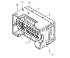
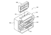
- FIG. 10 is a partial cross-sectional perspective view showing a conventional lever-type connector and a mating connector.
- FIG. 11 is a perspective view showing a housing and a retainer of the lever type connector shown in FIG.
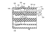
- FIG. 12 is a cross-sectional view showing the inner housing with the retainer in the temporary fitting position.
- FIG. 13 is a cross-sectional view showing the inner housing in which the retainer is in the main fitting position.
- a lever-type connector 100 shown in FIG. 10 includes a housing 110 in which a contact 101 (see FIGS. 12 and 13) is accommodated, and an electric wire 102 (see FIGS. 12 and 13) led out from the contact 101 accommodated in the housing 110.
- a wire cover 120 for covering and a lever 130 for fitting with the mating connector 200 are provided.
- the housing 110 includes an inner housing 140 having a plurality of contact housing holes 141 in which the contacts 101 are housed, and an outer housing 150 that houses the inner housing 140.
- the inner housing 140 is provided with a retainer fitting recess 142 that opens upward.
- a retainer 160 that secondarily locks the contact 101 accommodated in the contact accommodation hole 141 is fitted into the retainer fitting recess 142.
- a tool insertion hole 143 into which a tool 210 for operating the retainer 160 fitted in the retainer fitting recess 142 is inserted is provided on the back surface of the inner housing 140.
- a retainer insertion hole 151 into which the retainer 160 is inserted is provided on the upper surface of the outer housing 150.
- the retainer 160 is inserted into the retainer fitting recess 142 of the inner housing 140 via the retainer insertion hole 151 of the outer housing 150.
- the retainer 160 is arrange
- the contact 101 is inserted into the contact receiving hole 141 of the inner housing 140 in which the retainer 160 is disposed at the temporary fitting position.
- the contact 101 inserted into the contact accommodating hole 141 is primarily locked by a lance 144 provided in each contact accommodating hole 141 of the inner housing 140.
- the tool 210 is inserted into the tool insertion hole 143 of the inner housing 140, and the tip 211 of the inserted tool 210 is pressed against the inclined surface 161 provided on the retainer 160, thereby temporarily fitting.
- the retainer 160 in the mating position is moved to the main fitting position.
- FIG. 13 when the retainer 160 is moved to the main fitting position, the contact 101 inserted into the contact accommodating hole 141 of the inner housing 140 is secondarily locked by the retainer 160. . JP 2007-188783 A
- the lever-type connector 100 shown in FIG. 10 employs a configuration in which the inclined surface 161 of the retainer 160 is pushed by the tip 211 of the tool 210 in order to move the retainer 160 to the main fitting position. Therefore, in the lever-type connector 100, when the retainer 160 is moved, the direction in which the tool 210 is inserted does not match the direction in which the retainer 160 is moved. Therefore, the operation of moving the retainer 160 to the main fitting position. There is a problem that is not easy. When the retainer 160 cannot be completely moved to the main fitting position, the contact 101 is not completely locked by the retainer 160, and the contact 101 may fall off from the inner housing 140.
- the present invention has been made to solve the above-described problems of the prior art, and its purpose is to reliably perform secondary locking and release of secondary locking by a retainer with good workability. It is to provide a lever-type connector that can be performed.
- the lever-type connector according to the first invention includes an inner housing having a contact receiving hole extending along a predetermined direction; A retainer fitted to the inner housing along a direction orthogonal to the predetermined direction; An outer housing that houses the inner housing; It has a cam groove into which a cam pin provided on the mating connector is inserted, is accommodated in the outer housing, and is located between the fitting start position and the fitting completion position along the side surface in the orthogonal direction of the outer housing.
- a lever-type connector that locks to A first retainer operation hole is provided on a side of the retainer on the side surface in the orthogonal direction of the outer housing, The slider is provided with a second retainer operation hole, The first retainer operation hole and the second retainer operation hole communicate with each other only when the slider is disposed at the fitting completion position.
- the lever-type connector according to the first invention includes a retainer that is fitted to the inner housing along a direction orthogonal to the direction in which the contact housing hole extends.
- a first retainer operating hole is provided on the side of the side retainer in the direction orthogonal to the direction in which the contact housing hole of the outer housing extends.
- the slider is provided with a second retainer operation hole. And the structure which the 1st retainer operation hole and the 2nd retainer operation hole communicate is employ
- the retainer is temporarily mounted by the tip of the tool for operating the retainer inserted from the first retainer operation hole and the second retainer operation hole in a communicating state. It can be pushed into the fitting position or the main fitting position. That is, since the direction in which the tool is inserted coincides with the direction in which the retainer is moved, the retainer can be reliably moved to the temporary fitting position or the main fitting position with good workability.
- the lever connector according to the first invention adopts a configuration in which the first retainer operation hole and the second retainer operation hole communicate with each other only when the slider is disposed at the mating completion position. is doing. Therefore, according to the lever-type connector according to the first invention, when the retainer is moved to the main fitting position, when the slider is not arranged at the fitting completion position, the first retainer operation hole and Since the second retainer operation hole is not in communication, the retainer cannot be pushed by a tool. Therefore, according to the lever connector according to the first invention, it is possible to detect the displacement of the slider when the retainer is moved.
- the lever connector according to the second invention is the lever connector according to the first invention, wherein the second retainer operation hole is provided at a position avoiding the cam groove. To do. Therefore, according to the lever-type connector according to the second invention, it is possible to prevent the strength of the slider from being lowered by providing the second retainer operation hole while avoiding the cam groove.
- FIG. 4 is a front view of the housing shown in FIG. 3.
- FIG. 3 shows the state which decomposed
- FIG. 3 shows the housing in which a slider exists in a fitting completion position. It is sectional drawing of the housing shown in FIG.
- FIG. 1 It is a perspective view which shows the housing in which a slider exists in a fitting start position. It is sectional drawing of the housing shown in FIG. It is the perspective view which carried out the partial cross section which shows the conventional lever type connector and the other party connector. It is a perspective view which shows the housing and retainer of the lever-type connector shown in FIG. It is sectional drawing which shows the inner housing in which a retainer exists in a temporary fitting position. It is sectional drawing which shows the inner housing in which a retainer exists in this fitting position.
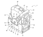
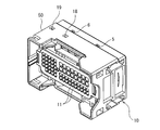
- FIG. 1 is a perspective view showing a state in which a lever of a lever-type connector according to an embodiment of the present invention is arranged at a fitting start position.
- FIG. 2 is a perspective view showing a state in which the lever of the lever-type connector shown in FIG. 1 is disposed at the fitting completion position.
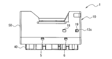
- FIG. 3 is a plan view of the housing of the lever-type connector shown in FIG.
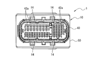
- FIG. 4 is a front view of the housing shown in FIG.
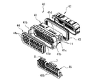
- FIG. 5 is a perspective view showing a state in which the inner housing constituting the housing shown in FIG. 3 is disassembled.
- FIG. 6 is a perspective view showing the housing in which the slider is in the fitting completion position.
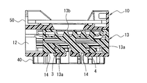
- 7 is a cross-sectional view of the housing shown in FIG.
- FIG. 8 is a perspective view showing the housing in which the slider is in the fitting start position.
- 9 is a cross-sectional view of the housing shown in FIG.
- a lever-type connector 1 shown in FIGS. 1 and 2 includes a housing 10 that houses a plurality of contacts (not shown), and a wire cover 20 that is attached to the back side of the housing 10 (the upper side shown in FIGS. 1 and 2). And a lever 30 attached to the wire cover 20.
- the housing 10 is formed so as to extend in the left-right direction (the left-right direction shown in FIGS. 3 and 4), and has an inner housing 40 and an outer housing 50 that houses the inner housing 40. And have.
- the inner housing 40 includes a housing main body 41, a front cover 42 and a first seal member 43 attached to the front side of the housing main body 41, and a second attached to the rear side of the housing main body 41.
- a seal member 44 and a retainer 45 fitted to the housing body 41 are provided.
- the housing body 41 has a plurality of contact housing holes 11 extending along the front-rear direction (vertical direction shown in FIG. 3). Each contact accommodating hole 11 is provided with a lance (not shown) for temporarily locking the contact.
- a hood portion 41a extending rearward is provided.
- Latch arms 41b for fixing the inner housing 40 to the outer housing 50 are provided at both ends in the left-right direction of the hood portion 41a.
- the housing main body 41 is provided with the retainer fitting recessed part 41c extended along an up-down direction.
- the retainer fitting recess 41c is open downward.
- two openings 41d through which the protrusions 7 and 8 of the retainer 45 fitted into the retainer fitting recess 41c penetrate are provided.
- the front cover 42 is formed so as to cover the front surface of the housing main body 41. As shown in FIG. 4, the front surface of the front cover 42 is provided with a plurality of mating terminal insertion ports 42 a that are continuous with the contact receiving holes 11 of the housing body 41.
- the front cover 42 is attached to the front surface of the housing main body 41.
- the first seal member 43 is formed in a ring shape. The first seal member 43 is attached to the outside of the housing body 41 and seals between the mating connector (not shown) and the housing body 41.
- the second seal member 44 is formed in a plate shape. Contact insertion holes 44 a are provided at positions corresponding to the contact receiving holes 11 of the housing body 41 of the second seal member 44.
- the second seal member 44 is accommodated in the hood portion 41a of the housing main body 41, and is brought into close contact with the outer peripheral surface of the electric wire led out from a contact (not shown) inserted into each contact insertion hole 44a. Prevent water from entering the interior of the housing 40.
- the retainer 45 is formed in a plate shape. Contact insertion holes 45 b are provided at positions corresponding to the contact receiving holes 11 of the housing body 41 of the retainer 45. At the upper end portion of the retainer 45, there are provided two projecting portions 7 and 8 that project from the respective opening portions 41d when the retainer 45 is fitted into the retainer fitting recess 41c of the housing body 41.
- the retainer 45 is fitted in the retainer fitting recess 41c of the housing body 41 along the vertical direction (in FIG. 5, from below to above). The retainer 45 fitted in the retainer fitting recess 41c of the housing main body 41 can be moved between the temporary fitting position and the main fitting position.
- the lever-type connector 1 is configured such that a contact can be inserted into the contact receiving hole 11 of the housing body 41 with the retainer 45 disposed at the temporary fitting position. Then, the retainer 45 placed in the temporary fitting position is pushed upward, and the retainer 45 is placed in the main fitting position, so that the retainer 45 is inserted into the contact receiving hole 11 of the housing body 41.
- the contact is configured to be secondarily locked.
- slider housing grooves 12 extending in the left-right direction are provided on both inner side surfaces of the outer housing 50 in the up-down direction (up-down direction shown in FIG. 4).
- a slider 13 is accommodated in each slider accommodating groove 12.
- Each slider 13 is accommodated in the slider accommodating groove 12 so that it can be freely moved along the left-right direction between a fitting start position (see FIG. 9) and a fitting completion position (see FIG. 7).
- Two first retainer operation holes 5 and 6 for inserting tools (not shown) for operating the retainer 45 are provided on the sides of the retainer 45 on both side surfaces in the vertical direction of the outer housing 50. It has been.
- the first retainer operation hole 5 is provided so as to communicate with the second retainer operation hole 3 of the slider 13 only when the slider 13 is disposed at the fitting completion position.
- the first retainer operation hole 6 is provided so as to communicate with the second retainer operation hole 4 of the slider 13 only when the slider 13 is disposed at the fitting completion position.
- the front surface of the outer housing 50 is provided with four cam pin insertion holes 14 into which cam pins (not shown) provided on the mating connector are inserted.
- Each cam pin insertion hole 14 is provided so as to communicate with each cam groove 13a of each slider 13 only when each slider 13 is disposed at the fitting start position.
- a first temporary fixing hole 18 and a second temporary fixing hole 19 into which the convex portion 13c of the slider 13 is fitted are provided on the upper surface and the lower surface of the outer housing 50, respectively.
- Each first temporary fixing hole 18 is provided so that the convex portion 13c of each slider 13 is fitted when each slider 13 is in the fitting start position.
- Each second temporary fixing hole 19 is provided so that the convex portion 13c of each slider 13 is fitted when each slider 13 is in the fitting completion position.
- Each slider 13 (see FIGS. 7 and 9) is formed in a flat plate shape and extends along the left-right direction. On the inner surface of each slider 13, two cam grooves 13a for pulling in and pushing out cam pins provided on the mating connector are provided along the left-right direction. A rack 13b (see FIGS. 7 and 9) to which the gear 32b of the lever 30 is fitted is provided on the back side of each slider 13. Each slider 13 is housed in the slider housing groove 12 of the outer housing 50, and can be moved between the fitting start position and the fitting completion position along the vertical side surface of the outer housing 50. Yes. At one end portion in the left-right direction of each slider 13, a convex portion 13 c for temporarily fastening the slider 13 at the fitting start position or the fitting completion position is provided.
- Each slider 13 is temporarily fastened at the fitting start position by fitting the convex portion 13 c into the first temporary fastening hole 18 of the outer housing 50.
- each slider 13 is temporarily fastened to the fitting completion position by fitting the convex portion 13 c into the second temporary fastening hole 19 of the outer housing 50.
- Each slider 13 is provided with two second retainer operation holes 3 and 4 into which a tool for operating the retainer 45 is inserted.
- the position in the front-rear direction of each second retainer operation hole 3, 4 in each slider 13 accommodated in the outer housing 50 and the position in the front-rear direction of the retainer 45 fitted in the inner housing 40 are defined. It almost matches.
- both the second retainer operating holes 3 and 4 are provided at positions avoiding the cam grooves 13a. Thereby, it is possible to prevent the strength of the slider 13 from being lowered.
- the lever 30 has a pair of side plates 32 and a connecting portion 33 that connects one end of each side plate 32 to each other.
- Bearing holes 32 a into which the shaft portions 21 of the wire covers 20 are fitted are provided at the other ends of the side plates 32.
- gears 32 b that fit into the racks 13 b of the slider 13 are provided around the bearing holes 32 a at the other ends of the both side plates 32.
- the wire cover 20 is formed in a substantially box shape so as to cover an electric wire (not shown) connected to a contact accommodated in the housing 10.
- shaft portions 21 that fit into the bearing holes 32 a of the lever 30 are provided.
- a first suppression portion 22 is provided on one side of the wire cover 20 in the left-right direction.
- a second suppression portion 23 is provided on the other side of the wire cover 20 in the left-right direction.
- the 1st suppression part 22 suppresses that the lever 30 arrange
- the 2nd suppression part 23 suppresses that the lever 30 arrange
- an electric wire outlet 24 At the other end of the wire cover 20 in the left-right direction, there is provided an electric wire outlet 24 through which electric wires connected to contacts accommodated in the housing 10 are led out in a bundled state.
- a lock member 27 is provided on the back surface of the wire cover 20 to prevent the lever 30 disposed at the mating completion position from rotating to one side in the left-right direction.
- the locking member 27 is formed in a cantilever plate spring shape, and the lever 30 is rotated to one side in the left-right direction by engaging the side surface of the connecting portion 33 of the lever 30 arranged at the fitting completion position. Stop.
- a locking convex portion 28 that prevents the lever 30 disposed at the fitting start position from rotating to the other side in the left-right direction is provided.
- Each locking convex portion 28 prevents the lever 30 from rotating to the other side in the left-right direction by locking the side surface of each side plate 32 of the lever 30 disposed at the fitting start position.
- the housing 10 in which the inner housing 40 is accommodated in the outer housing 50 in which both sliders 13 are accommodated and the wire cover 20 in which the lever 30 is attached are carried in.
- the wire cover 20 is carried into the assembly process in a state where the lever 30 is disposed at the fitting completion position and the lever 30 is fixed by the lock member 27 in order to prevent the lever 30 from being damaged.
- the housing 10 is assembled in a state where each slider 13 is arranged at the fitting completion position and the convex portion 13 c of each slider 13 is fitted in the second temporary fixing hole 19. It is carried into the process.
- the first retainer operation hole 5 and the second retainer operation hole 3 communicate with each other
- the first retainer operation hole 6 and the second retainer operation hole 6 communicate with each other.
- the retainer operation hole 4 is in communication with the retainer operation hole 4. Accordingly, the lower surface of the retainer 45 is connected via the second retainer operation holes 3 and 4 of the slider 13 on the lower surface side of the outer housing 50 and the first retainer operation holes 5 and 6 on the lower surface side of the outer housing 50. Is visible.
- a rod-shaped tool (not shown) is inserted into the first retainer operation holes 5 and 6 and the second retainer operation holes 3 and 4 that communicate with each other, and the lower surface of the retainer 45 is attached to the tip of the inserted tool. It can be pushed upward.
- the retainer 45 is reliably moved from the temporary fitting position to the main fitting position. It becomes possible to move with good sexuality. Then, by moving the retainer 45 to the main fitting position, the contact accommodated in the contact accommodating hole 11 of the inner housing 40 of the housing 10 is secondarily locked by the retainer 45.
- the lever connector 1 employs a configuration in which the position of each slider 13 accommodated in the housing 10 cannot be detected from the appearance. Therefore, in the lever-type connector 1, even when the slider 13 temporarily fixed at the fitting completion position in the housing 10 due to an impact or the like at the time of transporting the housing 10 occurs, the positional deviation of the slider 13 is displayed. Cannot be detected.
- the first retainer operation holes 5 and 6 and the second retainer operation holes 3 and 4 are continuous only when the slider 13 is in the fitting completion position.
- the structure which can perform 45 pushing is employ
- the lever type connector 1 when moving the retainer 45, it becomes possible to detect the position shift of the slider 13.
- the wire cover 20 with the lever 30 attached is attached to the housing 10 in which the retainer 45 is moved to the main fitting position.
- the lever 30 is disposed at the fitting completion position, and the lever 30 is fixed by the lock member 27.
- each slider 13 is arranged at the fitting completion position, and the convex portion 13 c of each slider 13 is fitted into the second temporary fixing hole 19.
- the wire cover 20 is attached to the housing 10, and the assembly of the lever-type connector 1 is completed.
- the gear 32b of the lever 30 drives the rack 13b of the slider 13, and the slider 13 is moved along the left-right direction.
- the lever 30 is rotated toward the fitting start position side (one side in the left-right direction)
- the slider 13 is moved toward the fitting start position side of the slider 13.
- the lever 30 is rotated toward the fitting completion position side (the other side in the left-right direction)
- the slider 13 is moved toward the fitting completion position side of the slider 13.
- the lever 30 is arranged at the fitting start position.
- the cam pins insertion holes 14 of the outer housing 50 are arranged in the respective sliders 13 by arranging the slider 13 at the mating start position. It communicates with the cam groove 13a.
- each cam pin of the mating connector is inserted into each cam groove 13a of each slider 13 via each cam pin insertion hole 14 of the outer housing 50, and the lever type The connector 1 and the mating connector are temporarily fitted.
- the slider 13 is arrange
- the lever 30 arranged at the fitting completion position is in a state in which the lock member 27 of the wire cover 20 is prevented from rotating toward the fitting start position.
- the locking of the lever 30 by the lock member 27 of the wire cover 20 is released, and the lever 30 arranged at the fitting completion position is fitted. Rotate toward the starting position.
- the sliders 13 are arranged at the fitting completion positions, and the convex portions 13 c of the sliders 13 are fitted in the second temporary fixing holes 19.
- the retainer 45 in the main fitting position is pushed downward, and the retainer 45 is moved to the temporary fitting position.
- the first retainer operation hole 5 and the second retainer operation hole 3 communicate with each other
- the first retainer operation hole 6 and the second retainer operation hole 6 communicate with each other.
- the retainer operation hole 4 is in communication with the retainer operation hole 4. Therefore, the upper surface of the protrusion 7 of the retainer 45 is connected via the second retainer operation hole 3 of the slider 13 on the upper surface side of the outer housing 50 and the first retainer operation hole 5 on the upper surface side of the outer housing 50. Is visible.
- the retainer 45 since the direction in which the tool is inserted matches the direction in which the retainer 45 is moved, the retainer 45 is reliably moved from the main fitting position to the temporary fitting position. It becomes possible to make it. Then, by moving the retainer 45 to the temporary fitting position, secondary locking by the retainer 45 of the contact accommodated in the contact accommodating hole 11 of the inner housing 40 of the housing 10 is released.
- the contacts released from the secondary locking by the retainer 45 can be replaced by releasing the primary locking by the lance of the housing 10 using a dedicated tool.
- the embodiments of the present invention have been described above, various modifications can be made in the above embodiments.
- the numbers of the first retainer operation holes 5 and 6 in the outer housing 50 and the second retainer operation holes 3 and 4 of the slider 13 can be appropriately increased or decreased.
- the retainer can be reliably moved to the temporary fitting position or the main fitting position with good workability. Moreover, according to the lever type connector which concerns on 1st invention, when moving a retainer, it becomes possible to detect the position shift of a slider. Moreover, according to the lever type connector which concerns on 2nd invention, it becomes possible to prevent that the intensity
Landscapes
- Details Of Connecting Devices For Male And Female Coupling (AREA)
- Connector Housings Or Holding Contact Members (AREA)
Abstract
リテーナによるコンタクトの二次的な係止及び二次的な係止の解除を確実に且つ作業性よく行うことが可能なレバー式コネクタを提供する。レバー式コネクタ1は、インナーハウジング40に嵌合されるリテーナ45と、インナーハウジング40を収容するアウターハウジング50と、嵌合開始位置と嵌合完了位置との間を移動させることが可能なスライダ13とを備える。レバー式コネクタ1では、リテーナ45を本嵌合位置に配置することによって、コンタクトが二次的に係止される。アウターハウジング50の上下方向の側面のリテーナ45の側方に、第一のリテーナ操作用孔5,6が設けられ、スライダ13に、第二のリテーナ操作用孔3,4が設けられている。そして、スライダ13が嵌合完了位置に配置されているときにのみ、第一のリテーナ操作用孔5,6と第二のリテーナ操作用孔3,4とが連通する。
Description
本発明は、レバーを回転させることによって相手コネクタとの嵌合及び嵌合の解除を行うレバー式コネクタに関する。
近年、自動車等の分野で用いられる電気コネクタでは多極化が進んでいる。そして、多極に形成された電気コネクタでは、コネクタ同士の嵌合を行う際及び嵌合を解除する際に大きな力が必要となる。このため、自動車等の分野では、レバーによる倍力効果を利用して相手コネクタとの嵌合及び嵌合の解除を行うレバー式コネクタが使用されている。
ここで、レバー式コネクタでは、インナーハウジングのコンタクト収容孔に収容されたコンタクトが該コンタクト収容孔から抜け落ちることを防止するために、リテーナでコンタクト収容孔に収容されたコンタクトを二次的に係止する構成が採用されている。そして、このタイプのレバー式コネクタでは、リテーナに外力が作用することによって該リテーナによるコンタクトの係止が意図せずに解除されることを防止するために、リテーナをアウターハウジングの内方に配置する構成が採用されている。
ここで、レバー式コネクタでは、インナーハウジングのコンタクト収容孔に収容されたコンタクトが該コンタクト収容孔から抜け落ちることを防止するために、リテーナでコンタクト収容孔に収容されたコンタクトを二次的に係止する構成が採用されている。そして、このタイプのレバー式コネクタでは、リテーナに外力が作用することによって該リテーナによるコンタクトの係止が意図せずに解除されることを防止するために、リテーナをアウターハウジングの内方に配置する構成が採用されている。
しかしながら、リテーナをアウターハウジングの内方に配置するタイプのレバー式コネクタでは、リテーナによるコンタクトの係止を行う際に、仮嵌合位置にあるリテーナを本嵌合位置に移動させづらいという問題がある。
従来、上記問題を解決するためのレバー式コネクタとして、例えば、図10から図13に示すものが知られている。
従来、上記問題を解決するためのレバー式コネクタとして、例えば、図10から図13に示すものが知られている。
図10は、従来のレバー式コネクタ及び相手コネクタを示す、部分断面した斜視図である。図11は、図10に示すレバー式コネクタのハウジング及びリテーナを示す斜視図である。図12は、リテーナが仮嵌合位置にあるインナーハウジングを示す断面図である。図13は、リテーナが本嵌合位置にあるインナーハウジングを示す断面図である。
図10に示すレバー式コネクタ100は、コンタクト101(図12及び図13参照)が収容されるハウジング110と、ハウジング110に収容されたコンタクト101から導出する電線102(図12及び図13参照)を覆うワイヤカバー120と、相手コネクタ200との嵌合を行うためのレバー130とを備えている。
図10に示すレバー式コネクタ100は、コンタクト101(図12及び図13参照)が収容されるハウジング110と、ハウジング110に収容されたコンタクト101から導出する電線102(図12及び図13参照)を覆うワイヤカバー120と、相手コネクタ200との嵌合を行うためのレバー130とを備えている。
図10及び図11に示すように、ハウジング110は、コンタクト101が収容されるコンタクト収容孔141を複数有するインナーハウジング140と、インナーハウジング140を収容するアウターハウジング150とを有している。
図12及び図13に示すように、インナーハウジング140には、上方に向かって開口するリテーナ嵌合凹部142が設けられている。リテーナ嵌合凹部142には、コンタクト収容孔141に収容されたコンタクト101を二次的に係止するリテーナ160が嵌合される。また、インナーハウジング140の背面には、リテーナ嵌合凹部142に嵌合されたリテーナ160を操作するための工具210が挿入される工具挿入孔143が設けられている。
図12及び図13に示すように、インナーハウジング140には、上方に向かって開口するリテーナ嵌合凹部142が設けられている。リテーナ嵌合凹部142には、コンタクト収容孔141に収容されたコンタクト101を二次的に係止するリテーナ160が嵌合される。また、インナーハウジング140の背面には、リテーナ嵌合凹部142に嵌合されたリテーナ160を操作するための工具210が挿入される工具挿入孔143が設けられている。
アウターハウジング150の上面には、リテーナ160が挿入されるリテーナ挿入孔151が設けられている。
インナーハウジング140のコンタクト収容孔141にコンタクト101を収容する際には、まず、リテーナ160を、アウターハウジング150のリテーナ挿入孔151を介してインナーハウジング140のリテーナ嵌合凹部142に挿入する。そして、図12に示すように、リテーナ160を仮嵌合位置に配置する。
インナーハウジング140のコンタクト収容孔141にコンタクト101を収容する際には、まず、リテーナ160を、アウターハウジング150のリテーナ挿入孔151を介してインナーハウジング140のリテーナ嵌合凹部142に挿入する。そして、図12に示すように、リテーナ160を仮嵌合位置に配置する。
次に、図12に示すように、リテーナ160が仮嵌合位置に配置されたインナーハウジング140のコンタクト収容孔141にコンタクト101を挿入する。コンタクト収容孔141に挿入されたコンタクト101は、インナーハウジング140の各コンタクト収容孔141内に設けられたランス144によって一次的に係止される。
そして、図12及び図13に示すように、インナーハウジング140の工具挿入孔143に工具210を挿入し、挿入した工具210の先端211でリテーナ160に設けられた斜面161を押すことによって、仮嵌合位置にあるリテーナ160を本嵌合位置に移動させる。そして、図13に示すように、リテーナ160が本嵌合位置に移動されることで、インナーハウジング140のコンタクト収容孔141に挿入されたコンタクト101が、リテーナ160によって二次的に係止される。
特開2007-188783号公報
そして、図12及び図13に示すように、インナーハウジング140の工具挿入孔143に工具210を挿入し、挿入した工具210の先端211でリテーナ160に設けられた斜面161を押すことによって、仮嵌合位置にあるリテーナ160を本嵌合位置に移動させる。そして、図13に示すように、リテーナ160が本嵌合位置に移動されることで、インナーハウジング140のコンタクト収容孔141に挿入されたコンタクト101が、リテーナ160によって二次的に係止される。
しかしながら、図10に示すレバー式コネクタ100では、リテーナ160を本嵌合位置に移動させるために工具210の先端211でリテーナ160の斜面161を押す構成を採用している。したがって、レバー式コネクタ100では、リテーナ160を移動させる際に、工具210が挿入される向きとリテーナ160が移動される向きとが一致していないため、リテーナ160を本嵌合位置に移動させる作業が容易ではないという問題がある。そして、リテーナ160を完全に本嵌合位置に移動させることができない場合には、リテーナ160によるコンタクト101の係止が不完全となり、インナーハウジング140からコンタクト101が抜け落ちるおそれがある。
本発明は上記した従来技術の問題を解決するためになされたものであり、その目的は、リテーナによるコンタクトの二次的な係止及び二次的な係止の解除を確実に且つ作業性よく行うことが可能なレバー式コネクタを提供することにある。
本発明は上記した従来技術の問題を解決するためになされたものであり、その目的は、リテーナによるコンタクトの二次的な係止及び二次的な係止の解除を確実に且つ作業性よく行うことが可能なレバー式コネクタを提供することにある。
第一の発明に係るレバー式コネクタは、所定方向に沿って延びるコンタクト収容孔を有するインナーハウジングと、
前記所定方向に対して直交する方向に沿って前記インナーハウジングに嵌合されるリテーナと、
前記インナーハウジングを収容するアウターハウジングと、
相手コネクタに設けられたカムピンが挿入されるカム溝を有し、前記アウターハウジング内に収容され、該アウターハウジングの前記直交方向の側面に沿って嵌合開始位置と嵌合完了位置との間を移動させることが可能なスライダと、
前記アウターハウジングに対して回転させることが可能となるように取り付けられ、回転によって前記スライダを移動させるレバーと、
を備え、
前記リテーナを仮嵌合位置に配置した状態で前記コンタクト収容孔にコンタクトが収容され、前記リテーナを本嵌合位置に配置することによって該リテーナが前記コンタクト収容孔に収容されたコンタクトを二次的に係止するレバー式コネクタであって、
前記アウターハウジングの前記直交方向の側面の前記リテーナの側方に、第一のリテーナ操作用孔が設けられ、
前記スライダに、第二のリテーナ操作用孔が設けられ、
前記スライダが嵌合完了位置に配置されているときにのみ、前記第一のリテーナ操作用孔と前記第二のリテーナ操作用孔とが連通することを特徴とする。
前記所定方向に対して直交する方向に沿って前記インナーハウジングに嵌合されるリテーナと、
前記インナーハウジングを収容するアウターハウジングと、
相手コネクタに設けられたカムピンが挿入されるカム溝を有し、前記アウターハウジング内に収容され、該アウターハウジングの前記直交方向の側面に沿って嵌合開始位置と嵌合完了位置との間を移動させることが可能なスライダと、
前記アウターハウジングに対して回転させることが可能となるように取り付けられ、回転によって前記スライダを移動させるレバーと、
を備え、
前記リテーナを仮嵌合位置に配置した状態で前記コンタクト収容孔にコンタクトが収容され、前記リテーナを本嵌合位置に配置することによって該リテーナが前記コンタクト収容孔に収容されたコンタクトを二次的に係止するレバー式コネクタであって、
前記アウターハウジングの前記直交方向の側面の前記リテーナの側方に、第一のリテーナ操作用孔が設けられ、
前記スライダに、第二のリテーナ操作用孔が設けられ、
前記スライダが嵌合完了位置に配置されているときにのみ、前記第一のリテーナ操作用孔と前記第二のリテーナ操作用孔とが連通することを特徴とする。
第一の発明に係るレバー式コネクタでは、コンタクト収容孔が延びる方向に対して直交する方向に沿ってインナーハウジングに嵌合されるリテーナを備えている。また、アウターハウジングのコンタクト収容孔が延びる方向に対して直交する方向の側面のリテーナの側方に、第一のリテーナ操作用孔が設けられている。さらに、スライダに、第二のリテーナ操作用孔が設けられている。そして、スライダが嵌合完了位置に配置されているときにのみ、第一のリテーナ操作用孔と第二のリテーナ操作用孔とが連通する構成を採用している。
これによって、第一の発明に係るレバー式コネクタでは、連通した状態の第一のリテーナ操作用孔及び第二のリテーナ操作用孔から挿入したリテーナを操作するための工具の先端によって、リテーナを仮嵌合位置又は本嵌合位置に押し込むことができる。すなわち、工具が挿入される向きとリテーナが移動される向きとが一致しているため、リテーナを仮嵌合位置又は本嵌合位置に確実に且つ作業性よく移動させることが可能となる。
ここで、レバー式コネクタでは、レバーが嵌合完了位置に配置されるとともにスライダが嵌合完了位置に配置された状態で組み立てが行われる。
そこで、第一の発明に係るレバー式コネクタでは、スライダが嵌合完了位置に配置されているときにのみ、第一のリテーナ操作用孔と第二のリテーナ操作用孔とが連通する構成を採用している。したがって、第一の発明に係るレバー式コネクタによれば、リテーナを本嵌合位置に移動させる際に、スライダが嵌合完了位置に配置されていない場合には、第一のリテーナ操作用孔と第二のリテーナ操作用孔とが連通していないため、工具によるリテーナの押し込みを行うことができない。よって、第一の発明に係るレバー式コネクタによれば、リテーナを移動させる際に、スライダの位置ずれを検出することが可能となる。
そこで、第一の発明に係るレバー式コネクタでは、スライダが嵌合完了位置に配置されているときにのみ、第一のリテーナ操作用孔と第二のリテーナ操作用孔とが連通する構成を採用している。したがって、第一の発明に係るレバー式コネクタによれば、リテーナを本嵌合位置に移動させる際に、スライダが嵌合完了位置に配置されていない場合には、第一のリテーナ操作用孔と第二のリテーナ操作用孔とが連通していないため、工具によるリテーナの押し込みを行うことができない。よって、第一の発明に係るレバー式コネクタによれば、リテーナを移動させる際に、スライダの位置ずれを検出することが可能となる。
また、第二の発明に係るレバー式コネクタは、第一の発明に係るレバー式コネクタにおいて、前記第二のリテーナ操作用孔は、前記カム溝を避けた位置に設けられていることを特徴とする。
したがって、第二の発明に係るレバー式コネクタによれば、カム溝を避けて第二のリテーナ操作用孔を設けることによって、スライダの強度が低下することを防止することが可能となる。
したがって、第二の発明に係るレバー式コネクタによれば、カム溝を避けて第二のリテーナ操作用孔を設けることによって、スライダの強度が低下することを防止することが可能となる。
1 レバー式コネクタ
3,4 第二のリテーナ操作用孔
5,6 第一のリテーナ操作用孔
7,8 突起部
10 ハウジング
11 コンタクト収容孔
12 スライダ収容溝
13 スライダ
13a カム溝
13b ラック
13c 凸部
14 カムピン挿入孔
18 第一仮留め孔
19 第二仮留め孔
20 ワイヤカバー
21 軸部
22 第一抑止部
23 第二抑止部
24 電線引出口
27 ロック部材
28 ロック用凸部
30 レバー
32 側板
32a 軸受孔
32b ギヤ
33 連結部
40 インナーハウジング
41 ハウジング本体
41a フード部
41b ラッチアーム
41c リテーナ嵌合凹部
41d 開口部
42 フロントカバー
42a 相手端子挿入口
43 第一シール部材
44 第二シール部材
44a コンタクト挿通孔
45 リテーナ
45b コンタクト挿通孔
50 アウターハウジング
3,4 第二のリテーナ操作用孔
5,6 第一のリテーナ操作用孔
7,8 突起部
10 ハウジング
11 コンタクト収容孔
12 スライダ収容溝
13 スライダ
13a カム溝
13b ラック
13c 凸部
14 カムピン挿入孔
18 第一仮留め孔
19 第二仮留め孔
20 ワイヤカバー
21 軸部
22 第一抑止部
23 第二抑止部
24 電線引出口
27 ロック部材
28 ロック用凸部
30 レバー
32 側板
32a 軸受孔
32b ギヤ
33 連結部
40 インナーハウジング
41 ハウジング本体
41a フード部
41b ラッチアーム
41c リテーナ嵌合凹部
41d 開口部
42 フロントカバー
42a 相手端子挿入口
43 第一シール部材
44 第二シール部材
44a コンタクト挿通孔
45 リテーナ
45b コンタクト挿通孔
50 アウターハウジング
次に本発明の実施形態であるレバー式コネクタを図面を参照して説明する。
図1は、本発明の実施形態であるレバー式コネクタのレバーが嵌合開始位置に配置された状態を示す斜視図である。図2は、図1に示すレバー式コネクタのレバーが嵌合完了位置に配置された状態を示す斜視図である。図3は、図1に示すレバー式コネクタのハウジングの平面図である。図4は、図3に示すハウジングの正面図である。図5は、図3に示すハウジングを構成するインナーハウジングを分解した状態を示す斜視図である。図6は、スライダが嵌合完了位置にあるハウジングを示す斜視図である。図7は、図6に示すハウジングの断面図である。図8は、スライダが嵌合開始位置にあるハウジングを示す斜視図である。図9は、図8に示すハウジングの断面図である。
図1は、本発明の実施形態であるレバー式コネクタのレバーが嵌合開始位置に配置された状態を示す斜視図である。図2は、図1に示すレバー式コネクタのレバーが嵌合完了位置に配置された状態を示す斜視図である。図3は、図1に示すレバー式コネクタのハウジングの平面図である。図4は、図3に示すハウジングの正面図である。図5は、図3に示すハウジングを構成するインナーハウジングを分解した状態を示す斜視図である。図6は、スライダが嵌合完了位置にあるハウジングを示す斜視図である。図7は、図6に示すハウジングの断面図である。図8は、スライダが嵌合開始位置にあるハウジングを示す斜視図である。図9は、図8に示すハウジングの断面図である。
図1及び図2に示すレバー式コネクタ1は、複数のコンタクト(図示せず)を収容するハウジング10と、ハウジング10の背面側(図1及び図2に示す上側)に取り付けられたワイヤカバー20と、ワイヤカバー20に取り付けられたレバー30とを備えている。
ハウジング10は、図3及び図4に示すように、左右方向(図3及び図4に示す左右方向)に沿って延びるように形成され、インナーハウジング40と、インナーハウジング40を収容するアウターハウジング50とを有している。
ハウジング10は、図3及び図4に示すように、左右方向(図3及び図4に示す左右方向)に沿って延びるように形成され、インナーハウジング40と、インナーハウジング40を収容するアウターハウジング50とを有している。
インナーハウジング40は、図5に示すように、ハウジング本体41と、ハウジング本体41の前面側に装着されるフロントカバー42及び第一シール部材43と、ハウジング本体41の背面側に装着される第二シール部材44と、ハウジング本体41に嵌合されるリテーナ45とを備えている。
ハウジング本体41は、図5に示すように、前後方向(図3に示す上下方向)に沿って延びるコンタクト収容孔11を複数有している。各コンタクト収容孔11には、コンタクトを一次的に係止するためのランス(図示せず)が設けられている。ハウジング本体41の背面側には、後方に向かって延びるフード部41aが設けられている。フード部41aの左右方向の両端部には、それぞれインナーハウジング40をアウターハウジング50に固定するためのラッチアーム41bが設けられている。そして、ハウジング本体41には、上下方向に沿って延びるリテーナ嵌合凹部41cが設けられている。リテーナ嵌合凹部41cは、下方に向かって開口している。また、ハウジング本体41のリテーナ嵌合凹部41cの上面側には、リテーナ嵌合凹部41cに嵌合されたリテーナ45の各突起部7,8が突き抜ける開口部41dが2つ設けられている。
ハウジング本体41は、図5に示すように、前後方向(図3に示す上下方向)に沿って延びるコンタクト収容孔11を複数有している。各コンタクト収容孔11には、コンタクトを一次的に係止するためのランス(図示せず)が設けられている。ハウジング本体41の背面側には、後方に向かって延びるフード部41aが設けられている。フード部41aの左右方向の両端部には、それぞれインナーハウジング40をアウターハウジング50に固定するためのラッチアーム41bが設けられている。そして、ハウジング本体41には、上下方向に沿って延びるリテーナ嵌合凹部41cが設けられている。リテーナ嵌合凹部41cは、下方に向かって開口している。また、ハウジング本体41のリテーナ嵌合凹部41cの上面側には、リテーナ嵌合凹部41cに嵌合されたリテーナ45の各突起部7,8が突き抜ける開口部41dが2つ設けられている。
フロントカバー42は、ハウジング本体41の前面を覆うように形成されている。図4に示すように、フロントカバー42の前面には、ハウジング本体41の各コンタクト収容孔11に連続する相手端子挿入口42aが複数設けられている。そして、フロントカバー42は、ハウジング本体41の前面に装着される。
第一シール部材43は、リング状に形成されている。そして、第一シール部材43は、ハウジング本体41の外側に装着され、相手コネクタ(図示せず)とハウジング本体41との間をシールする。
第一シール部材43は、リング状に形成されている。そして、第一シール部材43は、ハウジング本体41の外側に装着され、相手コネクタ(図示せず)とハウジング本体41との間をシールする。
第二シール部材44は、板状に形成されている。第二シール部材44のハウジング本体41の各コンタクト収容孔11に対応する位置には、コンタクト挿通孔44aが設けられている。そして、第二シール部材44は、ハウジング本体41のフード部41a内に収容され、各コンタクト挿通孔44aに挿入されたコンタクト(図示せず)から導出する電線の外周面に密着することによって、インナーハウジング40の内部への水の浸入を阻止する。
リテーナ45は、板状に形成されている。リテーナ45のハウジング本体41の各コンタクト収容孔11に対応する位置には、コンタクト挿通孔45bが設けられている。リテーナ45の上端部には、リテーナ45がハウジング本体41のリテーナ嵌合凹部41cに嵌合された際に各開口部41dから突出する2つの突起部7,8が設けられている。
そして、リテーナ45は、ハウジング本体41のリテーナ嵌合凹部41cに上下方向に沿って(図5では、下方から上方に向かって)嵌合される。ハウジング本体41のリテーナ嵌合凹部41cに嵌合されたリテーナ45は、仮嵌合位置と本嵌合位置との間を移動させることが可能となっている。レバー式コネクタ1では、リテーナ45を仮嵌合位置に配置した状態で、ハウジング本体41のコンタクト収容孔11にコンタクトを挿入することができるように構成されている。そして、仮嵌合位置に配置されているリテーナ45を上方に向かって押し込んで、リテーナ45を本嵌合位置に配置することによって、該リテーナ45がハウジング本体41のコンタクト収容孔11に挿入されたコンタクトを二次的に係止するように構成されている。
そして、リテーナ45は、ハウジング本体41のリテーナ嵌合凹部41cに上下方向に沿って(図5では、下方から上方に向かって)嵌合される。ハウジング本体41のリテーナ嵌合凹部41cに嵌合されたリテーナ45は、仮嵌合位置と本嵌合位置との間を移動させることが可能となっている。レバー式コネクタ1では、リテーナ45を仮嵌合位置に配置した状態で、ハウジング本体41のコンタクト収容孔11にコンタクトを挿入することができるように構成されている。そして、仮嵌合位置に配置されているリテーナ45を上方に向かって押し込んで、リテーナ45を本嵌合位置に配置することによって、該リテーナ45がハウジング本体41のコンタクト収容孔11に挿入されたコンタクトを二次的に係止するように構成されている。
図2に示すように、アウターハウジング50の上下方向(図4に示す上下方向)の両内側面には、それぞれ左右方向に沿って延びるスライダ収容溝12が設けられている。そして、図1に示すように、各スライダ収容溝12には、スライダ13が収容されている。各スライダ13は、嵌合開始位置(図9参照)と嵌合完了位置(図7参照)との間を左右方向に沿って自由に移動させることができるようにスライダ収容溝12に収容されている。アウターハウジング50の上下方向の両側面のリテーナ45の側方には、それぞれリテーナ45を操作するための工具(図示せず)が挿入される第一のリテーナ操作用孔5,6が2つ設けられている。ハウジング10では、アウターハウジング50の上下方向の各側面における各第一のリテーナ操作用孔5,6の前後方向の位置と、インナーハウジング40に嵌合されたリテーナ45の前後方向の位置とがほぼ一致している。第一のリテーナ操作用孔5は、スライダ13が嵌合完了位置に配置されているときにのみ、スライダ13の第二のリテーナ操作用孔3と連通するように設けられている。また、第一のリテーナ操作用孔6は、スライダ13が嵌合完了位置に配置されているときにのみ、スライダ13の第二のリテーナ操作用孔4と連通するように設けられている。
図4に示すように、アウターハウジング50の前面には、相手コネクタに設けられたカムピン(図示せず)が挿入されるカムピン挿入孔14が4つ設けられている。各カムピン挿入孔14は、各スライダ13が嵌合開始位置に配置されているときのみ、各スライダ13の各カム溝13aに連通するように設けられている。アウターハウジング50の上面及び下面には、それぞれスライダ13の凸部13cが嵌合する第一仮留め孔18及び第二仮留め孔19が設けられている。各第一仮留め孔18は、各スライダ13が嵌合開始位置にあるときに、各スライダ13の凸部13cが嵌合するように設けられている。各第二仮留め孔19は、各スライダ13が嵌合完了位置にあるときに、各スライダ13の凸部13cが嵌合するように設けられている。
各スライダ13(図7及び図9参照)は、平板状に形成され、左右方向に沿って延びている。各スライダ13の内面には、相手コネクタに設けられたカムピンの引き込み及び押し出しを行うカム溝13aが左右方向に沿って2つ設けられている。また、各スライダ13の背面側には、レバー30のギヤ32bが嵌合されるラック13b(図7及び図9参照)が設けられている。各スライダ13は、アウターハウジング50のスライダ収容溝12内に収容され、アウターハウジング50の上下方向の側面に沿って嵌合開始位置と嵌合完了位置との間を移動させることが可能となっている。各スライダ13の左右方向の一端部には、スライダ13を嵌合開始位置又は嵌合完了位置で仮留めするための凸部13cが設けられている。各スライダ13は、凸部13cがアウターハウジング50の第一仮留め孔18に嵌合することによって、嵌合開始位置に仮留めされる。また、各スライダ13は、凸部13cがアウターハウジング50の第二仮留め孔19に嵌合することによって、嵌合完了位置に仮留めされる。各スライダ13には、リテーナ45を操作するための工具が挿入される第二のリテーナ操作用孔3,4が2つ設けられている。ハウジング10では、アウターハウジング50に収容された各スライダ13における各第二のリテーナ操作用孔3,4の前後方向の位置と、インナーハウジング40に嵌合されたリテーナ45の前後方向の位置とがほぼ一致している。ここで、両第二のリテーナ操作用孔3,4は、それぞれカム溝13aを避けた位置に設けられている。これにより、スライダ13の強度が低下することを防止することが可能となる。
レバー30は、図1及び図2に示すように、一対の側板32及びこれら両側板32の一端を互いに連結する連結部33を有している。両側板32の他端部には、それぞれワイヤカバー20の軸部21が嵌合される軸受孔32aが設けられている。また、両側板32の他端部の軸受孔32aの周りには、それぞれスライダ13のラック13bに嵌合するギヤ32bが設けられている。
ワイヤカバー20は、図1及び図2に示すように、ハウジング10に収容されたコンタクトに接続されている電線(図示せず)を覆うようにほぼ箱形に形成されている。ワイヤカバー20の上面及び下面の前端部には、それぞれレバー30の軸受孔32aに嵌合する軸部21が設けられている。
ワイヤカバー20の左右方向の一方側には、第一抑止部22が設けられている。また、ワイヤカバー20の左右方向の他方側には、第二抑止部23が設けられている。第一抑止部22は、嵌合開始位置(図1参照)に配置されたレバー30がそれ以上左右方向の一方側へ回転されることを抑止する。第二抑止部23は、嵌合完了位置(図2参照)に配置されたレバー30がそれ以上左右方向の他方側へ回転されることを抑止する。ワイヤカバー20の左右方向の他端部には、ハウジング10に収容されたコンタクトに接続されている電線を束ねた状態で導出させる電線引出口24が設けられている。
ワイヤカバー20の左右方向の一方側には、第一抑止部22が設けられている。また、ワイヤカバー20の左右方向の他方側には、第二抑止部23が設けられている。第一抑止部22は、嵌合開始位置(図1参照)に配置されたレバー30がそれ以上左右方向の一方側へ回転されることを抑止する。第二抑止部23は、嵌合完了位置(図2参照)に配置されたレバー30がそれ以上左右方向の他方側へ回転されることを抑止する。ワイヤカバー20の左右方向の他端部には、ハウジング10に収容されたコンタクトに接続されている電線を束ねた状態で導出させる電線引出口24が設けられている。
ワイヤカバー20の背面には、嵌合完了位置に配置されたレバー30の左右方向の一方側への回転を阻止するロック部材27が設けられている。ロック部材27は、片持ち梁の板ばね状に形成され、嵌合完了位置に配置されたレバー30の連結部33の側面を係止することによってレバー30の左右方向の一方側への回転を阻止する。ワイヤカバー20の上面及び下面の一端部には、それぞれ嵌合開始位置に配置されたレバー30の左右方向の他方側への回転を阻止するロック用凸部28が設けられている。各ロック用凸部28は、嵌合開始位置に配置されたレバー30の各側板32の側面を係止することによって、レバー30の左右方向の他方側への回転を阻止する。
次に、レバー式コネクタ1の組み立て方法について説明する。
レバー式コネクタ1の組み立て工程には、両スライダ13が収容されたアウターハウジング50にインナーハウジング40が収容された状態のハウジング10及びレバー30が取り付けられた状態のワイヤカバー20が搬入される。
ワイヤカバー20は、レバー30の破損を防止するために、レバー30が嵌合完了位置に配置され、レバー30がロック部材27によって固定された状態で組み立て工程に搬入される。また、図6及び図7に示すように、ハウジング10は、各スライダ13が嵌合完了位置に配置されて、各スライダ13の凸部13cが第二仮留め孔19に嵌合した状態で組み立て工程に搬入される。これにより、レバー式コネクタ1の組み立て工程では、レバー30が嵌合完了位置に配置された状態のワイヤカバー20と各スライダ13が嵌合完了位置に配置された状態のハウジング10とを組み合わせれば、レバー30の各ギヤ32bと各スライダ13のラック13bとが正しく嵌合されるようになっている。さらに、ハウジング10では、ハウジング本体41のリテーナ嵌合凹部41cにリテーナ45が嵌合され、該リテーナ45が仮嵌合位置に配置された状態で組み立て工程に搬入される。
レバー式コネクタ1の組み立て工程には、両スライダ13が収容されたアウターハウジング50にインナーハウジング40が収容された状態のハウジング10及びレバー30が取り付けられた状態のワイヤカバー20が搬入される。
ワイヤカバー20は、レバー30の破損を防止するために、レバー30が嵌合完了位置に配置され、レバー30がロック部材27によって固定された状態で組み立て工程に搬入される。また、図6及び図7に示すように、ハウジング10は、各スライダ13が嵌合完了位置に配置されて、各スライダ13の凸部13cが第二仮留め孔19に嵌合した状態で組み立て工程に搬入される。これにより、レバー式コネクタ1の組み立て工程では、レバー30が嵌合完了位置に配置された状態のワイヤカバー20と各スライダ13が嵌合完了位置に配置された状態のハウジング10とを組み合わせれば、レバー30の各ギヤ32bと各スライダ13のラック13bとが正しく嵌合されるようになっている。さらに、ハウジング10では、ハウジング本体41のリテーナ嵌合凹部41cにリテーナ45が嵌合され、該リテーナ45が仮嵌合位置に配置された状態で組み立て工程に搬入される。
レバー式コネクタ1を組み立てる際には、まず、ハウジング10のアウターハウジング50からインナーハウジング40の複数のコンタクト収容孔11内に、それぞれコンタクトを収容する。インナーハウジング40の各コンタクト収容孔11に収容されたコンタクトは、コンタクト収容孔11に設けられたランスによって一次的に係止される。
次に、仮嵌合位置にあるリテーナ45を上方に向かって押し込み、リテーナ45を本嵌合位置に移動させる。
次に、仮嵌合位置にあるリテーナ45を上方に向かって押し込み、リテーナ45を本嵌合位置に移動させる。
ここで、スライダ13が嵌合完了位置にあるハウジング10では、第一のリテーナ操作用孔5と第二のリテーナ操作用孔3とが連通するとともに、第一のリテーナ操作用孔6と第二のリテーナ操作用孔4とが連通した状態となっている。したがって、連通するアウターハウジング50の下面側のスライダ13の第二のリテーナ操作用孔3,4及びアウターハウジング50の下面側の第一のリテーナ操作用孔5,6を介して、リテーナ45の下面が見える状態となっている。よって、連通する第一のリテーナ操作用孔5,6及び第二のリテーナ操作用孔3,4に棒状の工具(図示せず)を挿入して、挿入した工具の先端でリテーナ45の下面を上方に向かって押し込むことができる。
これにより、レバー式コネクタ1によれば、工具が挿入される向きとリテーナ45が移動される向きとが一致しているため、リテーナ45を仮嵌合位置から本嵌合位置に確実に且つ作業性よく移動させることが可能となる。
そして、リテーナ45を本嵌合位置に移動させることによって、ハウジング10のインナーハウジング40のコンタクト収容孔11に収容されたコンタクトがリテーナ45により二次的に係止される。
そして、リテーナ45を本嵌合位置に移動させることによって、ハウジング10のインナーハウジング40のコンタクト収容孔11に収容されたコンタクトがリテーナ45により二次的に係止される。
ここで、レバー式コネクタ1では、ハウジング10内に収容されている各スライダ13の位置を外観からは検知することができない構成を採用している。したがって、レバー式コネクタ1では、ハウジング10の搬送時の衝撃等によってハウジング10内の嵌合完了位置で仮留めされていたスライダ13に位置ずれが発生した場合でも、該スライダ13の位置ずれを外観から検知することができない。
そこで、レバー式コネクタ1では、スライダ13が嵌合完了位置にあるときにのみ第一のリテーナ操作用孔5,6及び第二のリテーナ操作用孔3,4が連続することによって、工具によるリテーナ45の押し込みを行うことができる構成を採用している。すなわち、レバー式コネクタ1では、スライダ13が嵌合完了位置にない場合には、第一のリテーナ操作用孔5,6及び第二のリテーナ操作用孔3,4が連続していないため、工具によるリテーナ45の押し込みを行うことができない。
これにより、レバー式コネクタ1によれば、リテーナ45を移動させる際に、スライダ13の位置ずれを検出することが可能となる。なお、アウターハウジング40及びスライダ13の色とリテーナ45の色とを異ならせると、スライダ13の位置ずれを目視で検知することが容易になる。
次に、リテーナ45を本嵌合位置に移動させたハウジング10に、レバー30が装着された状態のワイヤカバー20を取り付ける。この場合、上述したように、ワイヤカバー20では、レバー30が嵌合完了位置に配置され、レバー30がロック部材27によって固定された状態となっている。また、リテーナ45が本嵌合位置に配置されたハウジング10では、各スライダ13が嵌合完了位置に配置されて、各スライダ13の凸部13cが第二仮留め孔19に嵌合した状態となっている。したがって、レバー30が嵌合完了位置に配置された状態のワイヤカバー20と各スライダ13が嵌合完了位置に配置された状態のハウジング10とを組み合わせることにより、レバー30の各ギヤ32bと各スライダ13のラック13bとが正しく嵌合される。なお、ハウジング10へのワイヤカバー20の取り付けが完了した状態では、ハウジング10に収容された複数のコンタクトに接続されている電線が、束ねられた状態でワイヤカバー20の電線引出口24から導出される。
次に、リテーナ45を本嵌合位置に移動させたハウジング10に、レバー30が装着された状態のワイヤカバー20を取り付ける。この場合、上述したように、ワイヤカバー20では、レバー30が嵌合完了位置に配置され、レバー30がロック部材27によって固定された状態となっている。また、リテーナ45が本嵌合位置に配置されたハウジング10では、各スライダ13が嵌合完了位置に配置されて、各スライダ13の凸部13cが第二仮留め孔19に嵌合した状態となっている。したがって、レバー30が嵌合完了位置に配置された状態のワイヤカバー20と各スライダ13が嵌合完了位置に配置された状態のハウジング10とを組み合わせることにより、レバー30の各ギヤ32bと各スライダ13のラック13bとが正しく嵌合される。なお、ハウジング10へのワイヤカバー20の取り付けが完了した状態では、ハウジング10に収容された複数のコンタクトに接続されている電線が、束ねられた状態でワイヤカバー20の電線引出口24から導出される。
これにより、図2に示すように、ワイヤカバー20がハウジング10に取り付けられ、レバー式コネクタ1の組み立てが完了する。
次に、レバー式コネクタ1の作用について説明する。
レバー式コネクタ1では、ハウジング10に対してレバー30を回転させることによって、レバー30のギヤ32bがスライダ13のラック13bを駆動し、スライダ13が左右方向に沿って移動される。そして、レバー30を嵌合開始位置側(左右方向の一方側)に向かって回転させると、スライダ13がスライダ13の嵌合開始位置側に向かって移動される。また、レバー30を嵌合完了位置側(左右方向の他方側)に向かって回転させると、スライダ13がスライダ13の嵌合完了位置側に向かって移動される。そして、レバー30が嵌合開始位置に配置されているときには、図8及び図9に示すように、スライダ13はその嵌合開始位置に配置される。また、レバー30が嵌合完了位置に配置されているときには、図6及び図7に示すように、スライダ13はその嵌合完了位置に配置される。
次に、レバー式コネクタ1の作用について説明する。
レバー式コネクタ1では、ハウジング10に対してレバー30を回転させることによって、レバー30のギヤ32bがスライダ13のラック13bを駆動し、スライダ13が左右方向に沿って移動される。そして、レバー30を嵌合開始位置側(左右方向の一方側)に向かって回転させると、スライダ13がスライダ13の嵌合開始位置側に向かって移動される。また、レバー30を嵌合完了位置側(左右方向の他方側)に向かって回転させると、スライダ13がスライダ13の嵌合完了位置側に向かって移動される。そして、レバー30が嵌合開始位置に配置されているときには、図8及び図9に示すように、スライダ13はその嵌合開始位置に配置される。また、レバー30が嵌合完了位置に配置されているときには、図6及び図7に示すように、スライダ13はその嵌合完了位置に配置される。
レバー式コネクタ1と相手コネクタとの嵌合を行う際には、まず、レバー30を嵌合開始位置に配置する。レバー30が嵌合開始位置に配置された状態のレバー式コネクタ1では、スライダ13がその嵌合開始位置に配置されることによって、アウターハウジング50の各カムピン挿入孔14が、各スライダ13の各カム溝13aに連通する。
そして、レバー30が嵌合開始位置に配置された状態で、相手コネクタの各カムピンをアウターハウジング50の各カムピン挿入孔14を介して各スライダ13の各カム溝13a内に挿入して、レバー式コネクタ1と相手コネクタとを仮嵌合する。
そして、レバー30が嵌合開始位置に配置された状態で、相手コネクタの各カムピンをアウターハウジング50の各カムピン挿入孔14を介して各スライダ13の各カム溝13a内に挿入して、レバー式コネクタ1と相手コネクタとを仮嵌合する。
次に、ワイヤカバー20のロック用凸部28によるレバー30のロックを解除し、嵌合開始位置に配置されているレバー30を、嵌合完了位置側に向かって回転させる。レバー30を嵌合完了位置側に向かって回転させると、スライダ13がその嵌合完了位置側に向かって移動されることによって、スライダ13の複数のカム溝13aが、それぞれ相手コネクタに設けられたカムピンを背面側に向かって引き込んでいく。これにより、レバー式コネクタ1のインナーハウジング40に収容されている複数のコンタクトが、それぞれ相手コネクタに収容されているコンタクトに嵌合される。
そして、レバー30を嵌合完了位置に配置することによって、スライダ13がその嵌合完了位置に配置され、レバー式コネクタ1と相手コネクタとの嵌合が完了する。なお、嵌合完了位置に配置されたレバー30は、ワイヤカバー20のロック部材27によって嵌合開始位置側への回転が阻止された状態となっている。
一方、レバー式コネクタ1と相手コネクタとの嵌合を解除する際には、ワイヤカバー20のロック部材27によるレバー30のロックを解除し、嵌合完了位置に配置されているレバー30を、嵌合開始位置側に向かって回転させる。レバー30を嵌合開始位置側に向かって回転させると、スライダ13がその嵌合開始位置側に向かって移動されることによって、スライダ13の複数のカム溝13aが、それぞれ相手コネクタに設けられたカムピンを前面側に向かって押し出していく。これにより、レバー式コネクタ1のインナーハウジング40に収容されているコンタクトと相手コネクタに収容されているコンタクトとの嵌合が解除される。
一方、レバー式コネクタ1と相手コネクタとの嵌合を解除する際には、ワイヤカバー20のロック部材27によるレバー30のロックを解除し、嵌合完了位置に配置されているレバー30を、嵌合開始位置側に向かって回転させる。レバー30を嵌合開始位置側に向かって回転させると、スライダ13がその嵌合開始位置側に向かって移動されることによって、スライダ13の複数のカム溝13aが、それぞれ相手コネクタに設けられたカムピンを前面側に向かって押し出していく。これにより、レバー式コネクタ1のインナーハウジング40に収容されているコンタクトと相手コネクタに収容されているコンタクトとの嵌合が解除される。
そして、レバー30を嵌合開始位置まで回転させると、レバー式コネクタ1と相手コネクタとの嵌合の解除が完了する。
次に、レバー式コネクタ1のコンタクトの差し替えを行う方法について説明する。
レバー式コネクタ1のコンタクトの差し替えを行う際には、まず、レバー30を、嵌合完了位置に配置する。そして、レバー30が嵌合完了位置に配置された状態のワイヤカバー20を、ハウジング10から取り外す。
次に、レバー式コネクタ1のコンタクトの差し替えを行う方法について説明する。
レバー式コネクタ1のコンタクトの差し替えを行う際には、まず、レバー30を、嵌合完了位置に配置する。そして、レバー30が嵌合完了位置に配置された状態のワイヤカバー20を、ハウジング10から取り外す。
ワイヤカバー20が取り外されたハウジング10では、各スライダ13がその嵌合完了位置に配置されて、各スライダ13の凸部13cが第二仮留め孔19に嵌合した状態となっている。
次に、本嵌合位置にあるリテーナ45を下方に向かって押し込み、リテーナ45を仮嵌合位置に移動させる。
次に、本嵌合位置にあるリテーナ45を下方に向かって押し込み、リテーナ45を仮嵌合位置に移動させる。
ここで、スライダ13が嵌合完了位置にあるハウジング10では、第一のリテーナ操作用孔5と第二のリテーナ操作用孔3とが連通するとともに、第一のリテーナ操作用孔6と第二のリテーナ操作用孔4とが連通した状態となっている。したがって、連通するアウターハウジング50の上面側のスライダ13の第二のリテーナ操作用孔3及びアウターハウジング50の上面側の第一のリテーナ操作用孔5を介して、リテーナ45の突起部7の上面が見える状態となっている。また、連通するアウターハウジング50の上面側のスライダ13の第二のリテーナ操作用孔4及びアウターハウジング50の上面側の第一のリテーナ操作用孔6を介して、リテーナ45の突起部8の上面が見える状態となっている。よって、連通する第一のリテーナ操作用孔5,6及び第二のリテーナ操作用孔3,4に棒状の工具を挿入して、挿入した工具の先端でリテーナ45の突起部7,8の上面を下方に向かって押し込むことができる。
このように、レバー式コネクタ1によれば、工具が挿入される向きとリテーナ45が移動される向きとが一致しているため、リテーナ45を本嵌合位置から仮嵌合位置に確実に移動させることが可能となる。
そして、リテーナ45を仮嵌合位置に移動させることによって、ハウジング10のインナーハウジング40のコンタクト収容孔11に収容されたコンタクトのリテーナ45による二次的な係止が解除される。
そして、リテーナ45を仮嵌合位置に移動させることによって、ハウジング10のインナーハウジング40のコンタクト収容孔11に収容されたコンタクトのリテーナ45による二次的な係止が解除される。
そして、リテーナ45による二次的な係止が解除されたコンタクトは、専用の工具を用いてハウジング10のランスによる一次的な係止を解除することによって、差し替えを行うことができる。
以上、本発明の実施の形態について説明したが、上記実施の形態では、種々の変更を行うことが可能である。
例えば、アウターハウジング50における第一のリテーナ操作用孔5,6及びスライダ13の第二のリテーナ操作用孔3,4の数は、適宜増減することが可能である。
以上、本発明の実施の形態について説明したが、上記実施の形態では、種々の変更を行うことが可能である。
例えば、アウターハウジング50における第一のリテーナ操作用孔5,6及びスライダ13の第二のリテーナ操作用孔3,4の数は、適宜増減することが可能である。
第一の発明に係るレバー式コネクタによれば、リテーナを仮嵌合位置又は本嵌合位置に確実に且つ作業性よく移動させることが可能となる。また、第一の発明に係るレバー式コネクタによれば、リテーナを移動させる際に、スライダの位置ずれを検出することが可能となる。
また、第二の発明に係るレバー式コネクタによれば、さらに、スライダの強度が低下することを防止することが可能となる。
また、第二の発明に係るレバー式コネクタによれば、さらに、スライダの強度が低下することを防止することが可能となる。
Claims (2)
- 所定方向に沿って延びるコンタクト収容孔を有するインナーハウジングと、
前記所定方向に対して直交する方向に沿って前記インナーハウジングに嵌合されるリテーナと、
前記インナーハウジングを収容するアウターハウジングと、
相手コネクタに設けられたカムピンが挿入されるカム溝を有し、前記アウターハウジング内に収容され、該アウターハウジングの前記直交方向の側面に沿って嵌合開始位置と嵌合完了位置との間を移動させることが可能なスライダと、
前記アウターハウジングに対して回転させることが可能となるように取り付けられ、回転によって前記スライダを移動させるレバーと、
を備え、
前記リテーナを仮嵌合位置に配置した状態で前記コンタクト収容孔にコンタクトが収容され、前記リテーナを本嵌合位置に配置することによって該リテーナが前記コンタクト収容孔に収容されたコンタクトを二次的に係止するレバー式コネクタであって、
前記アウターハウジングの前記直交方向の側面の前記リテーナの側方に、第一のリテーナ操作用孔が設けられ、
前記スライダに、第二のリテーナ操作用孔が設けられ、
前記スライダが嵌合完了位置に配置されているときにのみ、前記第一のリテーナ操作用孔と前記第二のリテーナ操作用孔とが連通することを特徴とするレバー式コネクタ。 - 前記第二のリテーナ操作用孔は、前記カム溝を避けた位置に設けられていることを特徴とする請求項1記載のレバー式コネクタ。
Priority Applications (3)
| Application Number | Priority Date | Filing Date | Title |
|---|---|---|---|
| CN2009801125529A CN101983460B (zh) | 2008-04-04 | 2009-03-26 | 杆式连接器 |
| EP09727652A EP2278667A4 (en) | 2008-04-04 | 2009-03-26 | CONNECTOR OF THE LEVER TYPE |
| US12/897,110 US7922504B2 (en) | 2008-04-04 | 2010-10-04 | Lever-type connector |
Applications Claiming Priority (2)
| Application Number | Priority Date | Filing Date | Title |
|---|---|---|---|
| JP2008098017A JP2009252488A (ja) | 2008-04-04 | 2008-04-04 | レバー式コネクタ |
| JP2008-098017 | 2008-04-04 |
Related Child Applications (1)
| Application Number | Title | Priority Date | Filing Date |
|---|---|---|---|
| US12/897,110 Continuation US7922504B2 (en) | 2008-04-04 | 2010-10-04 | Lever-type connector |
Publications (1)
| Publication Number | Publication Date |
|---|---|
| WO2009123012A1 true WO2009123012A1 (ja) | 2009-10-08 |
Family
ID=41135391
Family Applications (1)
| Application Number | Title | Priority Date | Filing Date |
|---|---|---|---|
| PCT/JP2009/056124 Ceased WO2009123012A1 (ja) | 2008-04-04 | 2009-03-26 | レバー式コネクタ |
Country Status (5)
| Country | Link |
|---|---|
| US (1) | US7922504B2 (ja) |
| EP (1) | EP2278667A4 (ja) |
| JP (1) | JP2009252488A (ja) |
| CN (1) | CN101983460B (ja) |
| WO (1) | WO2009123012A1 (ja) |
Cited By (1)
| Publication number | Priority date | Publication date | Assignee | Title |
|---|---|---|---|---|
| EP2369691A1 (en) * | 2010-03-26 | 2011-09-28 | Tyco Electronics Japan G.K. | Lever type electrical connector |
Families Citing this family (25)
| Publication number | Priority date | Publication date | Assignee | Title |
|---|---|---|---|---|
| JP5607446B2 (ja) * | 2010-07-20 | 2014-10-15 | 矢崎総業株式会社 | コネクタ |
| JP5588773B2 (ja) * | 2010-07-28 | 2014-09-10 | タイコエレクトロニクスジャパン合同会社 | ワイヤカバー、電気コネクタ |
| JP5662210B2 (ja) * | 2011-03-16 | 2015-01-28 | 矢崎総業株式会社 | レバー治具及びコネクタ装置 |
| JP5830406B2 (ja) * | 2012-02-20 | 2015-12-09 | 矢崎総業株式会社 | レバー式コネクタ |
| JP5957346B2 (ja) * | 2012-09-12 | 2016-07-27 | 矢崎総業株式会社 | コネクタ |
| JP6193060B2 (ja) * | 2013-09-02 | 2017-09-06 | タイコエレクトロニクスジャパン合同会社 | レバー式電気コネクタ |
| JP2016207414A (ja) * | 2015-04-21 | 2016-12-08 | 住友電装株式会社 | コネクタ |
| JP1549393S (ja) | 2015-06-26 | 2016-05-16 | ||
| JP1549392S (ja) * | 2015-06-26 | 2016-05-16 | ||
| JP1549513S (ja) | 2015-06-26 | 2016-05-16 | ||
| JP1549512S (ja) * | 2015-06-26 | 2016-05-16 | ||
| DE102015111505B4 (de) * | 2015-07-15 | 2018-03-08 | Vibracoustic Gmbh | Trennvorrichtung und Hydrolager |
| US9748693B1 (en) * | 2016-02-10 | 2017-08-29 | Yazaki North America, Inc. | Connector position assurance with identification feature |
| JP6605431B2 (ja) * | 2016-11-17 | 2019-11-13 | 矢崎総業株式会社 | コネクタ |
| EP3392979B1 (en) * | 2017-04-19 | 2020-01-29 | Aptiv Technologies Limited | Electrical connector with lever and methods of assembling thereof |
| JP6931561B2 (ja) * | 2017-07-04 | 2021-09-08 | 日本航空電子工業株式会社 | コネクタ |
| JP6647739B2 (ja) * | 2017-08-25 | 2020-02-14 | 矢崎総業株式会社 | コネクタとコネクタカバーとの組み付け構造 |
| CN108832348B (zh) * | 2018-06-26 | 2024-01-30 | 合兴汽车电子(太仓)有限公司 | 连接器 |
| JP6929821B2 (ja) * | 2018-06-26 | 2021-09-01 | タイコエレクトロニクスジャパン合同会社 | 電気コネクタ |
| CN110444953A (zh) * | 2019-03-04 | 2019-11-12 | 安波福中央电气(上海)有限公司 | 多孔位母端连接器 |
| US10897103B1 (en) * | 2019-09-12 | 2021-01-19 | Aptiv Technologies Limited | Electrical connector with seal protection |
| JP7256096B2 (ja) * | 2019-09-13 | 2023-04-11 | モレックス エルエルシー | コネクタ及びコネクタ組立体 |
| JP7209192B2 (ja) * | 2019-11-15 | 2023-01-20 | 住友電装株式会社 | コネクタ |
| JP7476816B2 (ja) * | 2021-01-29 | 2024-05-01 | 住友電装株式会社 | コネクタ |
| CN114709664B (zh) * | 2021-12-27 | 2024-10-29 | 安波福中央电气(上海)有限公司 | 稳定装置、连接器组件以及连接器组装体 |
Citations (4)
| Publication number | Priority date | Publication date | Assignee | Title |
|---|---|---|---|---|
| JPH10241773A (ja) * | 1997-02-28 | 1998-09-11 | Sumitomo Wiring Syst Ltd | 分割コネクタ |
| JP2000133375A (ja) * | 1998-10-30 | 2000-05-12 | Sumitomo Wiring Syst Ltd | レバー式コネクタ |
| JP2006331991A (ja) * | 2005-05-30 | 2006-12-07 | Tyco Electronics Amp Kk | レバー式コネクタ |
| JP2007234420A (ja) * | 2006-03-01 | 2007-09-13 | Sumitomo Wiring Syst Ltd | コネクタ |
Family Cites Families (8)
| Publication number | Priority date | Publication date | Assignee | Title |
|---|---|---|---|---|
| FR2702889B1 (fr) * | 1993-03-18 | 1995-04-21 | Cinch Connecteurs Sa | Connecteur électrique . |
| EP0722203B1 (en) * | 1995-01-16 | 2003-04-16 | Molex Incorporated | Electrical connector assembly with improved camming system |
| JP2000315549A (ja) * | 1999-04-28 | 2000-11-14 | Sumitomo Wiring Syst Ltd | コネクタ |
| US7361036B2 (en) * | 2005-10-06 | 2008-04-22 | Fci Americas Technology, Inc. | Electrical connector with lever and latch |
| JP2007188783A (ja) | 2006-01-13 | 2007-07-26 | Yazaki Corp | コネクタ |
| JP4655960B2 (ja) * | 2006-02-24 | 2011-03-23 | 住友電装株式会社 | コネクタ |
| JP4252603B2 (ja) * | 2007-01-31 | 2009-04-08 | タイコエレクトロニクスアンプ株式会社 | 電気コネクタ |
| JP4941064B2 (ja) * | 2007-04-09 | 2012-05-30 | 住友電装株式会社 | レバー式コネクタ |
-
2008
- 2008-04-04 JP JP2008098017A patent/JP2009252488A/ja active Pending
-
2009
- 2009-03-26 CN CN2009801125529A patent/CN101983460B/zh active Active
- 2009-03-26 WO PCT/JP2009/056124 patent/WO2009123012A1/ja not_active Ceased
- 2009-03-26 EP EP09727652A patent/EP2278667A4/en not_active Withdrawn
-
2010
- 2010-10-04 US US12/897,110 patent/US7922504B2/en active Active
Patent Citations (4)
| Publication number | Priority date | Publication date | Assignee | Title |
|---|---|---|---|---|
| JPH10241773A (ja) * | 1997-02-28 | 1998-09-11 | Sumitomo Wiring Syst Ltd | 分割コネクタ |
| JP2000133375A (ja) * | 1998-10-30 | 2000-05-12 | Sumitomo Wiring Syst Ltd | レバー式コネクタ |
| JP2006331991A (ja) * | 2005-05-30 | 2006-12-07 | Tyco Electronics Amp Kk | レバー式コネクタ |
| JP2007234420A (ja) * | 2006-03-01 | 2007-09-13 | Sumitomo Wiring Syst Ltd | コネクタ |
Cited By (1)
| Publication number | Priority date | Publication date | Assignee | Title |
|---|---|---|---|---|
| EP2369691A1 (en) * | 2010-03-26 | 2011-09-28 | Tyco Electronics Japan G.K. | Lever type electrical connector |
Also Published As
| Publication number | Publication date |
|---|---|
| US7922504B2 (en) | 2011-04-12 |
| CN101983460A (zh) | 2011-03-02 |
| US20110021048A1 (en) | 2011-01-27 |
| CN101983460B (zh) | 2013-06-12 |
| EP2278667A1 (en) | 2011-01-26 |
| EP2278667A4 (en) | 2011-08-03 |
| JP2009252488A (ja) | 2009-10-29 |
Similar Documents
| Publication | Publication Date | Title |
|---|---|---|
| WO2009123012A1 (ja) | レバー式コネクタ | |
| JP4405564B2 (ja) | レバー式コネクタ | |
| JP4591228B2 (ja) | コネクタ | |
| JP4387438B2 (ja) | レバー式コネクタ | |
| JP4382134B2 (ja) | レバー式コネクタ | |
| JP4468465B2 (ja) | レバー式コネクタ | |
| JP4849007B2 (ja) | コネクタ | |
| US8777648B2 (en) | Electrical connector with easily separable inner and outer housings | |
| WO2010098184A1 (ja) | スライドカム付きコネクタ | |
| JP2018067378A (ja) | コネクタ | |
| WO2016059947A1 (ja) | コネクタ | |
| JP5172871B2 (ja) | レバー式コネクタ | |
| JP2007188783A (ja) | コネクタ | |
| JP4556134B2 (ja) | コネクタ | |
| JP3570534B2 (ja) | コネクタ | |
| JP7610783B2 (ja) | 防水コネクタ | |
| JP4513677B2 (ja) | 防水コネクタ | |
| JP7643977B2 (ja) | ハウジングユニット | |
| JP6015628B2 (ja) | コネクタ | |
| JP2009272046A (ja) | レバー式コネクタ | |
| JP2007026758A (ja) | 防水コネクタ | |
| JP2011044386A (ja) | 分割コネクタ | |
| JP2003249313A (ja) | 分割コネクタ | |
| JP2010257913A (ja) | コネクタ | |
| JP2014044801A (ja) | コネクタ |
Legal Events
| Date | Code | Title | Description |
|---|---|---|---|
| WWE | Wipo information: entry into national phase |
Ref document number: 200980112552.9 Country of ref document: CN |
|
| 121 | Ep: the epo has been informed by wipo that ep was designated in this application |
Ref document number: 09727652 Country of ref document: EP Kind code of ref document: A1 |
|
| NENP | Non-entry into the national phase |
Ref country code: DE |
|
| WWE | Wipo information: entry into national phase |
Ref document number: 2009727652 Country of ref document: EP |