WO2009127097A1 - Method and apparatus of communication - Google Patents

Method and apparatus of communication Download PDF

Info

Publication number
WO2009127097A1
WO2009127097A1 PCT/CN2008/070719 CN2008070719W WO2009127097A1 WO 2009127097 A1 WO2009127097 A1 WO 2009127097A1 CN 2008070719 W CN2008070719 W CN 2008070719W WO 2009127097 A1 WO2009127097 A1 WO 2009127097A1
Authority
WO
WIPO (PCT)
Prior art keywords
vector
class
sign
vectors
leader
Prior art date
Legal status (The legal status is an assumption and is not a legal conclusion. Google has not performed a legal analysis and makes no representation as to the accuracy of the status listed.)
Ceased
Application number
PCT/CN2008/070719
Other languages
French (fr)
Inventor
Peter Vary
Hauke Krüger
Bernd Geiser
Current Assignee (The listed assignees may be inaccurate. Google has not performed a legal analysis and makes no representation or warranty as to the accuracy of the list.)
Huawei Technologies Co Ltd
Original Assignee
Huawei Technologies Co Ltd
Priority date (The priority date is an assumption and is not a legal conclusion. Google has not performed a legal analysis and makes no representation as to the accuracy of the date listed.)
Filing date
Publication date
Application filed by Huawei Technologies Co Ltd filed Critical Huawei Technologies Co Ltd
Priority to PCT/CN2008/070719 priority Critical patent/WO2009127097A1/en
Priority to EP08734077.4A priority patent/EP2274833B1/en
Priority to CN2008801287020A priority patent/CN102132494B/en
Publication of WO2009127097A1 publication Critical patent/WO2009127097A1/en
Priority to US12/905,852 priority patent/US8364476B2/en
Anticipated expiration legal-status Critical
Ceased legal-status Critical Current

Links

Classifications

    • HELECTRICITY
    • H03ELECTRONIC CIRCUITRY
    • H03MCODING; DECODING; CODE CONVERSION IN GENERAL
    • H03M7/00Conversion of a code where information is represented by a given sequence or number of digits to a code where the same, similar or subset of information is represented by a different sequence or number of digits
    • H03M7/30Compression; Expansion; Suppression of unnecessary data, e.g. redundancy reduction
    • H03M7/3082Vector coding
    • GPHYSICS
    • G10MUSICAL INSTRUMENTS; ACOUSTICS
    • G10LSPEECH ANALYSIS TECHNIQUES OR SPEECH SYNTHESIS; SPEECH RECOGNITION; SPEECH OR VOICE PROCESSING TECHNIQUES; SPEECH OR AUDIO CODING OR DECODING
    • G10L19/00Speech or audio signals analysis-synthesis techniques for redundancy reduction, e.g. in vocoders; Coding or decoding of speech or audio signals, using source filter models or psychoacoustic analysis

Definitions

  • the technical field includes communications and signal processing. More particularly, the invention relates to a method and apparatus providing data processing of low complexity for spherical vector quantization, SVQ.
  • analogue speech is distributed in electrical signals over phone wires.
  • the speech is still carried in analogue electrical signals from the phone to a switch of the operator, where it is digitized so as to allow reconstruction within predefined requirements or criteria as regards distortion of the analogue signal.
  • the speech signal is compressed before the digitization providing a digital signal for distribution.
  • the compressors provide signals of reduced dynamics but are essentially lossless, since the analogue signal could be expanded in a receiver. This compression is known as A-law or ⁇ -law compression. At the receiving end, the signal is then expanded.
  • analogue samples of time-continuous sound are quantized into a fixed number of bits (16 bits) with no compression of the quantized data.
  • the limita- tion of sound samples to fixed levels provides some difference between the digitized samples and the analogue samples.
  • TTiis is known as quantization noise or distortion. Since the number of quantization levels is great (2 16 ), the distortion is negligible compared to the noise produced in analogue components of most audio CD players or amplifiers and loudspeakers.
  • a communications channel may include media such as electromagnetic storage, electronic memories, propagation of signals in traveling waves of electromagnetic fields from a transmitting antenna to a receiving antenna, or propagation of optical signals from an optical transmitter to a receiver for optical signals.
  • Telephone systems, CDs, digital portable audio players and television broadcasting all provide examples of communications over a communications channel.
  • the fixed wire provides a communications channel for the telephone system, the CD for the distribution of audio from a studio to a listener via a CD player, ' the flash memory or other storage medium for the portable audio player or the radio channel for television broadcasting.
  • Gray and Neuhoff refer quantization to "the division of a quantity into a discrete number of small parts.” As an example, any real number can be rounded off to the nearest integer. In binary computing, integers are commonly represented by sequences of binary digits, bits, thereby providing a binary representation of the quantized real number. Other example data representations exist as well.
  • Quantization and source coding have their origins in pulse code modulation, PCM, the system used for audio CD recording.
  • a PCM system consists fundamentally of three components: a sampler (11), a quantizer (12) and an encoder (13) as schematically illustrated in figure 1.
  • Sampling converts a continuous time waveform (14) into a discrete time waveform (14).
  • Quantization (12) of the samples (15) renders the quantized samples (16) to be approximations of the unquantized samples (15).
  • the quantized samples, or indices thereof, are transmitted on a communications channel (17) as provided by the encoder (13).
  • SQ scalar quantization
  • each (quantized) sample is independently encoded into a fixed number of bits, and correspondingly decoded into a reproduction. For a given distortion or reconstruction error, scalar quantization generally requires comparatively greater data rates than vector quantization, VQ.
  • VQ Vector quantization
  • SQ scalar quantization
  • VQ makes use of a k-dimensional partition or a fc-dimensional codebook, C, comprising lc-dimensional code vectors, each code vector representing a cell of vectors with mini- mum distortion according to a predefined criterion, such as minimum Euclidean distance.
  • a predefined criterion such as minimum Euclidean distance.
  • VQ as compared to SQ is that it inherently can exploit memory of source signals to be quantized / source signals such as the discrete time sequence (14) of the sampled waveform. Thereby, source signals such as speech signals or image signals commonly comprising memory or dependencies between different samples can be represented more efficiently. Also VQ comprises merits on its own and 7 in principle / SQ cannot perform better in terms of distortion versus rate than the best VQ. In prior art, the price for this improvement has been paid by increased complexity of, particularly, the encoder.
  • Figure 2 illustrates a simplified block diagram for vector quantization.
  • a signal sequence (285) is represented by vectors (281) and signals (286) carrying the vectors are mapped (282) into an index (287) corresponding to a representation or codeword of the codebook / a code vector, providing a minimum distortion encoding of the vectors (286) according to a predefined criterion or measure, e.g. Euclidean distance.
  • the vector to be represented (288) and the quantized vector or a representative thereof (289) are exchanged between the minimum distortion determining entity (282) and the entity comprising the code book representation (283).
  • the reconstructed vector is achieved by using a similar code- book and looking up the code vector represented by the received index.
  • transmission on a communications channel comprises all technical arrangements for distributing or communicating a signal from a source sender to a destination as schematically illustrated in figure 3.
  • a sequence representing a code index (34, 35) is transmitted through a communications channel (32) to the destination where it is decoded in the receiver (33).
  • the channel may be considered to comprise channel coding as need be to transmit or detect errors on a transmission channel.
  • channel encoders and decoders separated from the source encoding and decoding are included in physical transmitters and receivers, respectively. So, from the viewpoint of the source encoding, also parts of physical transmitters and receivers are frequently included in the communications channel (32).
  • Figure 4 illustrates schematically a flowchart for iteratively determining a codebook Y according to a generalized Lloyd algorithm, frequently referred to as an LBG algorithm (as disclosed by Y. Linde A. Buzo and R. Gray).
  • the algorithm is initiated (41) by initializing a counter m, an initial codebook Y 0 , a maximum possible (within the applicable range of the application) distortion
  • a partitioning S m defining the cells surrounding the various code vectors of the code book is determined (42) for the code book Y m , and the distortion D m is determined (43).
  • the algorithm is interrupted (44) when the relative distortion is smaller than the precision set initially.
  • a refined codebook is determined, the iteration counter is updated (46) and the process repeats for another iteration starting with determining a partitioning for the refined codebook (42).
  • the LBG algorithm is commonly considered to be computational expensive in terms of number of instructions when there is a great number of quantization levels. It is also sensitive to the initial choice of codebook (41). Also the amount of read-only memory, ROM, required by a trained vector quantizer is usually considered to be too large. Another problem is related to the LBG algorithm being trained to provide minimum distortion for a particular training data sequence. If data from another source with substantially different statistical properties is quantized, the performance is most often suboptimal. For vectors of dimension 1, the LBG quantizer reduces to the scalar Lloyd-Max quantizer.
  • VQ provides a method for creating a codebook providing the smallest distortion, e.g. in terms of Euclidean distance or squared Euclidean distance, given a certain statistic of the input signal based on the calculation of a point density function from the probability density function, PDF, of the input signal.
  • Structured codebooks do not exploit linear or non-linear dependency to increase the quantization performance that vector quantizers are generally capable of. At least linear dependencies, however / can be transformed to provide a benefit in quantization performance by means of Linear Prediction or Transform Coding. Therefore, the structured vector quantizers are designed such that they have high performance for memory less sources.
  • a lattice vector quantizer is a vector quantizer of which the codebook is composed of vectors which are arranged in a regular lattice according to a mathematical rule.
  • a lattice in general is a subset of an L v -dimensional vector space but consists of a countable infinite number of points,
  • the number of weighting factors ⁇ ,- determines the lattice's degree of freedom and is also called the dimension of the lattice can be greater or smaller than l v .
  • the dimension equals the dimension of the vector space in which the basis vectors are defined.
  • equation 1 is equivalent to a representation including a generator matrix M, where the factors ⁇ j as before are integer weight factors and L v is the dimension of the vector space.
  • Figure 5 illustrates an example two dimensional hexagonal lattice and corresponding basis vectors forming the generator matrix M. There are four vectors (51, 52, 53, 54) depicted. Vectors [ ] [ (52) span the same set of points as do
  • An example generator matrix providing the lattice is consequently Another example generator matrix of the lattice is
  • lattices are the Gosset lattice, , the Coxeter-Todd-Lattice, K 12 , the Barnes-Wall lattice A 16 , and the Leech Lattice A .
  • a permutation code defines all vectors of a codebook by means of class-leader vectors, , of dimension .
  • a class-leader vector is composed of coordinate entries ⁇ comprising components taken from a set o real val ues p, sorted in decreasing order
  • u> ⁇ is the weight related to real value ⁇ ; and is the number of occurrences of real value ⁇ lf 0 ⁇ K L ⁇ ,
  • a permutation of a class-leader vector is a vector that is composed of the same real values, as but in a different order.
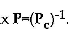
  • the corresponding permutation operation can be specified by means of matrix, P, referred to as the permutation matrix.
  • P matrix
  • the relation between and ⁇ could then be expressed as An example permutation vector reversing the sequence order is
  • the permutation processing is preferably realized in a digital signal processor, DSP, adapted for the permutation of interest.
  • High speed applications may require the permutations to be implemented in hardware, which can be achieved by employment of e.g. shift register circuitry.
  • Reversal of sequence order is e.g. achieved by storing the vector components in a shift register of the same length as the vector, in component- wise sequential order, and feeding out the shift register content in the reverse order. This is illustrated in figure 6.
  • the example shift register is composed of a number of D latches (601- 603).
  • the vector to be reversed is input (604) to the shift register through closed switches (605-607) during a sequence of clock cycles during which one component of the vector is input after another.
  • the shift register of figure 6 could be replaced by memory circuitry or a storage medium for storing controlled by a signal processor.
  • the corresponding processing comprises storing the vector components in the memory or storage medium and reading out the memory content or stored content component wise in the reverse order.
  • Ny is known as the multinomial coefficient.
  • a vector index is useful for describing and understanding the encoding process and mapping of code vectors. Since all permuted vectors are composed of the same coordinate values but in different order, the absolute value, or length, of the code vectors is identical for all permutated vectors. Using the vector index, this is
  • a further issue in the quantization process relates to compaction or how to represent the various vectors with fewer class representatives, such that the errors introduced by information loss due to the compaction will be acceptably small, or at best not be noticeable, to a user.
  • x y of a permutation code that provides the minimum Euclidean distance is achieved as follows. For a vector x of dimension to be (further) quantized or compacted, permute the vector coordinates such that the components of the permuted vecto are ordered in decreasing order The required permutations are represented by a matrix
  • the ordered vector x * is represented by a class-leader vector as specified in equation 7 and that also has its components sequentially ordered according to magnitude. For reconstructing x from x * , the process is reversed x
  • the matrix also provides a minimum Euclidean distance representative for the vector x to be quantized or compressed.
  • a vector index, i ⁇ is determined for the vector representative This is achieved by a permutation to index mapping and which is preferably achieved by a mapping suggested by J. Pieter and M. Schalkwijk.
  • mapping consequently transforms the permuted vector into an index .
  • a decoder realizes the reverse operation and maps the index p back into a permuted
  • the index i ⁇ providing a representation of the permuted vector suitable for transmission, storage or fur ther processing such as for channel encoding.
  • the index is suitable for transfer on a communications channel.
  • the number of indices is equal to the number of possible permutations, (see equation 11).
  • US Patent No. 4075622 describes a method and apparatus for data compression which utilizes a random walk through Pascal's triangle directed by an incoming binary source sequence.
  • the random walk starts at the apex of Pascal's triangle and proceeds downward according to an algorithm until it terminates at a boundary which has been constructed in such a way that the encoding of each source sequence can be accomplished in a fixed number of bits.
  • LfS Patent No. 6054943 describes a variable-to-block universal multilevel digital information compression making use of a random walk in Pascal's hypervolume, a multi-dimensional generalization of Pascal's triangle.
  • Codewords and decoded source sequences are either determined in the encoder and decoder, respectively, on the fly at encoding/decoding or pre-computed and stored.
  • Variable length sequences of source symbols are encoded into fixed length codeword blocks.
  • Encoders and decoders including dedicated hardware including registers, counters and latches are disclosed as are flowcharts.
  • Figure 26 of US6054943 illustrates graphically an example encoding (and decoding) of an example sequence of a ternary source.
  • a particular candidate prefix is selected and a running sum is updated.
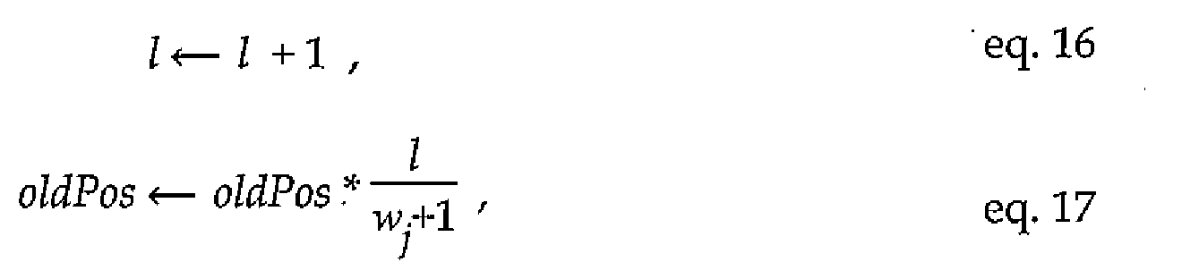
  • oldPos is the old position in Pascal's hyper volume.
  • the position in Pascal's hyper volume is similarly updated recursively for the next iteration,
  • I corresponds to the number of symbols that have come in.
  • the recursion for decoding works the path through Pascal's hyper volume for choos- ing a symbol / that provides a position that is not greater than a candidate for the corresponding position in the hyper volume.
  • the recursion for the running sum in reverse direction, decoding position / of a codeword, in US6054943 is
  • Hamkins describes wrapped spherical codes as vector quantizers for a memoryless Gaussian source and provides an algorithmic description of an encoder in table 6.1 quantizing gain and shape of a vector independently, the gain corresponding to the length or radius of the vector, and the shape corresponding to the vector normalized to 1.
  • the gain codebook is optimized by the Lloyd-Max algorithm. Since the PDF is known (Gaussian source), no training is required.
  • the algorithmic description is also included in Jon Hamkins and Kenneth Zeger, Gaussian Source Coding with Spherical Codes, IEEE Transactions on Information Theory, vol. 48, No. 11, pp. 2980- 2989 (2002).
  • class-leader vectors for representing source - data tend to be large, thereby requiring substantial storage capacity of e.g. codebook representation for encoding and decoding in digital communications equipment.
  • codebook representation for encoding and decoding in digital communications equipment.
  • a great number of class leaders requires a great time for determining the code vector in the encoding process in order to minimize distortion.
  • None of the cited documents provides a method or system of quantization or coding wherein a metric or distortion forming a criterion according to which a signal, or (us- ing vector notation) code vector or codeword, to output for an unquantized input signal, or vector, is determined from a reduced set of code vectors of an E-lattice being linked to the (full) set of code vectors by a sign distribution.
  • Speech encoding and decoding for speech communications in mobile telephone systems sound encoding for storage of songs and decoding for reproducing the sound in portable audio players or surround sound equipment reproducing movie sound, or other multi-channel sound, stored on a DVD or CD or received from public broadcasting companies by wire or over the air and image coding and decoding for digital television are some communications examples well known to the public.
  • the invention provides a method and system implementing sub-dividing a set of class-leader vectors of a vector quantization encoder or decoder for encoding and decoding of communications data and mapping of corresponding data as described in detail below in relation to encoding and decoding processes.
  • Figure 1 schematically illustrates a sampler, a quantizer and a coder according to prior art.
  • Figure 2 illustrates a simplified block diagram for vector quantization according to prior art.
  • Figure 3 illustrates schematically transmission on a communications channel according to prior art.
  • Figure 4 demonstrates schematically a flowchart for iteratively determining a code- book according to a generalized Lloyd algorithm of prior art.
  • Figure 5 illustrates an example two dimensional hexagonal lattice in prior art.
  • Figure 6 depicts a block diagram of an example shift register according to prior art.
  • Figure 7 shows a basic block diagram for parallel quantization of a radius and a normalized vector according to prior art.
  • Figure 8 shows a basic block diagram for serial quantization of a radius and a normalized vector according to an example mode of the invention.
  • Figure 9 plots an example distribution of code vectors according to the invention.
  • Figure 10 illustrates a flowchart of an efficient quantization procedure according to the invention.
  • Figure 11 illustrates schematically sub-ranges corresponding to equivalence classes in relation to root-vector classes for a simplified example according to the invention.
  • Figure 12 displays a flowchart illustrating example indexing in an embodiment of the invention.
  • Figure 13 depicts a basic flowchart for quantization according to an embodiment of the invention.
  • Figure 14 shows a simplified flowchart for determining a transformed distortion metric according to a preferred embodiment of the invention.
  • Figure 15 illustrates schematically indexing providing codewords from quantized data according to an embodiment of the invention.
  • Figure 16 illustrates schematically a flow-chart of a preferred decoder according to the invention.
  • Figure 17 displays schematically preferred index processing of code vectors of category A according to the invention.
  • Figure 18 illustrates schematically preferred index processing of code vectors of category B according to the invention.
  • Figure 19 monitors a simplified block diagram of example equipment according to the invention.
  • Vector quantizers based on structured codebooks generally provide a good compromise between memory requirement, computational complexity and quantization performance for practical use.
  • PDF the theoretically optimal code-vector point-density-function for a given input signal PDF is well approximated by structured codebooks such as lattice codebooks and permutation codebooks. These codebooks are not stored completely in memory and are searched efficiently for codebooks according to the invention.
  • Spherical vector quantization is a quantization that approximates the optimal code-vector point-density for the Gaussian distribution and at the same time can be realized efficiently. If properly designed, the achieved signal to noise ratio, SNR, re- lated to SVQ is independent from the PDF of the input signal and from the dynamics of the input signal for a wide dynamic range.
  • an example input signal representing an input signal vector, x is transformed into a signal representing a radius, of
  • the vector, x, and a normalized vector Both the radius and the normalized vector will be quantized to produce a quantized radius, / and a quantized normalized vector with the codebooks for the radius and for the normalized vector. In the sequel is referred to as a spherical code vector and as the codebook for the spherical vectors.
  • the radius is quantized by means of logarithmic quantization, e.g. A-law quantization well known from compression of PCM in telephone systems
  • the quantization signal to noise ratio, SNR / is independent of the probability density function of the input signal. This is also referred to as logarithmic SVQ.
  • FIG. 7 shows a basic block diagram for parallel quantization of a radius (72) and a normalized vector (73).
  • the radius and normalized vector are quantized independently.
  • Both the block (71) separating the radius and the spherical vector and the quantizers (72), (73) are preferably included in an encoder entity, whereas the combining entity (74) is preferably included in a decoder entity.
  • the output signal repre- senting an output vector, x, of the combining entity (74) is the reconstructed value of the input signal represented as input vector x.
  • the figure does not include processing equipment of index determining for reasons of simplicity. Signaling carrying codewords corresponding to indices are preferably transferred on a communications channel. Accordingly, the invention preferably includes processing equipment for index determining.
  • Figure 8 shows a basic block diagram for- serial quantization of a radius (82) and a normalized vector (83).
  • both the block (81) separat- ing the radius and the spherical vector and the quantizers (82), (83) are preferably included in an encoding entity, whereas the combining entity (84) is preferably included in a decoder entity.
  • the radius quantization is performed after the quantization of the normalized vector, c. This will allow for considering the curvature of the quantization cells, which is effective particularly for large cells. Especially for low bit rates, the sequential approach provides a slightly higher performance.
  • the output signal representing an output vector, x, of the combining entity (84) is the reconstructed value of the input signal represented as
  • an encoder preferably comprises equipment for determining one or more indices. Signaling carrying codewords corresponding to indices rather than quantized vectors are preferably transferred on a communications channel.
  • the code vectors are located on the surface of spheres, which for the 2-dimensional case are circles. The radii differs for code vectors on different circles (92), (93).
  • the scalar radius quantizer, Q R , (72), (82) is preferably realized by electrical circuitry implementing a lookup table, since the number of quantization and reconstruction levels is usually modest and, consequently, the number of entries required to be stored is small, particularly if logarithmic quantization is applied.
  • the quantization process is, e.g., realized by processing circuitry implementing a bisection based on a table containing all interval bounds. The sequential combination of the quantizers is referred to as re-quantization of the radius.
  • a quantized vector (code vector) as .
  • the index of the code vector denotes required and sufficient information to reconstruct the code vector in the decoder.
  • SVQ logarithmic SVQ
  • N is the number of code vectors for the normalized vector and N R is the number of available quantizer reconstruction values for the radius.
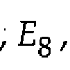
  • a Gosset Low Complexity Vector Quantizer is based on code vectors from a lattice derived from the well known Gosset lattice, E 8 .
  • the E 8 lattice is known to have the highest possible density of points in eight dimensions.
  • the invention identifies advantages as regards encoding and decoding that can be achieved based on a generalized Gosset lattice, E-lattice. Thereby efficiency gains as regards computational complexity and memory/storage require- ments are achieved.
  • the Gosset lattice was originally designed for eight dimensions, .
  • L ⁇ 8
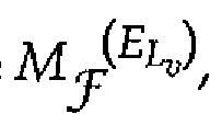
  • Lattice vectors with a same distance to the origin define a shell, S , of the lattice.
  • S a shell with a squared distance to the origin equal to 2M is denoted S ( EL V' .
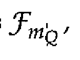
  • Each E-lattice spherical vector codebook , X ⁇ 1 ⁇ K is composed of all vectors related to a specific shell of squared radius Iu , normalized to radius 1,
  • N 0 ⁇ o ⁇ is the number of code vectors located on a shell with radius ⁇ j2u of
  • r eff Sp shells of successively greater radii of the lattice of interest are investigated one by one, starting with a shell of smallest radius, i.e. smallest natural number u, when constructing the codebook.
  • the codebook is finally based upon a shell w S p , with as many code vectors as possible provided that the effective bit rate per sample does not exceed the effective target bit rate per sample,
  • Table 1 Number of code vectors on different shells of the Gosset lattice.
  • a codebook for encoding and decoding according to the invention based on a particular E-lattice is also referred to by the particular shell or by the half of its squared radius, .
  • the E-lattice is invariant under an interchange of vector coordinates.
  • AU spherical code vectors can be grouped into a number, M of equivalence classes, Each equivalence class is composed of vectors generated by a permutation code given the class-leader vector Hence, the spherical vector codebook can be expressed as a superposition of codebooks, X ⁇ , of a permutation code T m ,
  • an efficient quantiza- tion procedure is as follows and as also illustrated in the flowchart of figure 10.
  • reordering corresponding to a permutation matrix P c is determined such that when applied to the normalized vector, the coordinates of the vector are rearranged in decreasing order (101).
  • Class-leader vectors are usually pre-stored in read-only memory or other storage medium. From the set of all the class-leader vectors, S E candidate g [ is, e.g., searched and selected (102) by processing
  • circuitry from the equivalence classes that out of the stored class leader vectors provides minimum distortion with respect to the (unquantized) vector c , according to a predefined criterion, such as minimum squared Euclidean distance,
  • the spherical code vector preferred to represent c is determined (103) by processing the class-leader vector representative corresponding to applying the inverse of the permutation matrix Hence, the spherical code vector determined to represent the normalized vector c is The quantized vector c is mapped (104) to a codeword, or index, in digital sig nal processing equipment. This is preferably achieved by applying the Schalkwijk algorithm / well-known in the art, to the particular code of the invention as follows.
  • sub-ranges 111), (112), (113), (114) corresponding to the equivalence classes and are determined as schematically illustrated in figure 11, for the example case of four equivalence classes.
  • the example sub-ranges are not uniform. Index offset corresponding to the sub-ranges, included in figure 11 for are preferably stored for each of the sub-ranges (111), (112), (113), (114) to speed-up encoding or decoding and then need not be transferred on the communications channel.
  • the sub-ranges are further sub-divided into smaller sub-ranges, and at last there is a single index.
  • Figure 12 displays a flowchart illustrating an example indexing as explained above for encoding of a sequence for communication over a communications channel.
  • Indexing is initialized (121), where wt( ⁇ ) denotes the weight or the number of occurrences of a particular symbol.
  • the rank of an incoming symbo is determined (122) and the index is updated accordingly by the sum of number of indices in correspond- ing sub-range (123).
  • the weights are updated (124) and the recursion continues for the next incoming symbol (125) until the last symbol of the code vector have been encoded (126).
  • the index then finally results from the last recursion (127).
  • the invention identifies that in many cases a great number of equivalence classes are involved depending on, e.g., dimensionality and sphere radius.
  • dimensionality and sphere radius As a non-exclusive example illustrated in table 2, the number of equivalence classes, 0 is
  • the requirements on the quantization equipment is substantially relieved by a quantizer implementing grouping of equivalence classes, ⁇ m , in root classes
  • ⁇ m equivalence classes
  • the number of classes is reduced from 162 to 11 for the Gosset lattice, or more than by a factor of 10, providing a load reduction in a corresponding order of magnitude, while providing identically the same codewords and distortion, e.g. in terms of minimum Euclidean distance.
  • the root classes consider two categories of code vectors, labeled categories A and B.
  • Vectors of category A are in D and comply with the require ⁇
  • each vector of category B can be expressed in terms of a vector comprising integer components, , in as for y in equation 26 from the relation while the radius of the vector remains unchanged.
  • a sign parity check sum for code vectors c is defined.
  • class-leader vectors can be constructed from class-leader root- vectors where is the number of root classes, each comprising one class-leader root-vecto .
  • the required codebook size e.g., is substantially reduced by doing so for most codes based on E-lattices of practical interest.
  • the encoding complexity is reduced, since not all class leader vectors need to be searched during the encoding.
  • the class-leader root-vectors are searched. In the preferred embodiment, there is a small additional computational load due to searching for category-B vectors providing minimum distortion.
  • a class-leader root- vector is composed of Ly
  • class-leader root-vector can be expressed as
  • the number of code vectors is limited and only a limited set of the vectors constructed by the lattice rule is considered.
  • Lattice vector quantizers in general are very well suited for quantization also for the reason that no explicit codebook has to be stored but could be determined from, e.g., its generator matrix.
  • the codebook will be structured, thereby facilitating fast search for code vectors.
  • lattice vector quantization is an efficient example of quantization.
  • Figure 13 depicts a basic flowchart for quantization according to an embodiment of the invention.
  • a vector x to be quantized it is preferably normalized to a vector c of radius 1 (131) to simplify subsequent processing.
  • Each component of the (normalized) vector is separated into respective magnitude and sign to form a mag- nitude vector and a sign vector (132),
  • the magnitude vector is permuted to arrange the components in decreasing order (133), and the sign vector is permuted accordingly (133),
  • the permuted magnitude vector can also be written
  • a metric is usually considered a quantity to be maximized. However, this specification preferably refers to a quantity to be minimized, similar to a distance. The difference merely resides in a different sign. The negative distance is maximized when the distance is minimized.
  • a distortion metric D m - preferably a Euclidean distance, is
  • the correlation could be maximized. Equivalently, the negative correlation could be minimized, since the distortion measure in equation 53 equals V V W / where Q is a constant corresponding to the lengths of vectors ⁇ and For normalized vectors and consequently equals 2.
  • the subsequent processing conditionally depends on whether the selected class-leader root- vector is of category A or B and the distortion V determined initially, conditionally requires to be transformed to correspond to the distortion of the class-leader vectors (135).
  • the class-leader root-vector providing the least (transformed) distortion, $ is se- lected for the output of the quantization processing (136).
  • Figure 14 shows a simplified flowchart for determining a transformed distortion metric.
  • the class-leader vector which achieves the lowest distortion is determined by the sign distribution of the permuted sign vector which is identical to the sign distribution of the class- leader vector.
  • the distortion is the same for the class-leader vector as for the class-leader root- vector of category A (142).
  • the class-leader vector has identically the same sign distribution as the permuted sign vector (143), as was also the case for category A above.
  • the permuted sign vector is corrected accordingly by increasing the permuted sign- vector component in position by 1 (modulo 2),
  • This operation corresponds to an XOR operation ⁇ inverting a sign bit in position in a binary representation of
  • one or more indices are preferred to the code vector for information transfer on a communications channel.
  • an indexing machine and related processing has been developed beyond previous work of e.g. Pieter and Schalkwijk.
  • the indexing is preferably performed as follows and schematically illustrated in the flowchart of figure 15 and implemented in processing equipment (191), (194) of figure 19.
  • the quantization index codeword is then determined (154) as described in relation to equation 36 on page 26 considering permutation matrix P c , where the permutation matrix P c of the normalized vector c, output from, e.g., the indexing provided by Pieter and Schalkwijk, replaces P of equation 36.
  • the offset s set in relation to the equivalence class of interest and is incorporated in the inde for communication on the communications channel.
  • index range grouping in relation to example root-vector classes is demonstrated.
  • root class represents example equivalence classes and example root class J corresponds to equivalence class 3 ( )
  • indexing of class-leader vectors is performed on the basis of the sign vector in equation 52.
  • in equation 51 is preferably indexed similarly, though is not necessarily binary, while is bi- nary.
  • the sign vector with corrected position as in equation 59 is preferably indexed.
  • Codeword representation by a class-leader root-vector in place of a plurality of class- leader vectors due to tine suggested sign separation and parity constraint provides substantial complexity reduction according to preferred embodiments of the inven- tion.
  • preferred embodiments of the invention provide reduced vector searches, searching an equivalence root class instead of searching a plurality of equivalence classes for a codeword providing least distortion.
  • the invention identifies the fact that the equivalence classes, related to one equivalence root class, , are based on vector components with the same amplitudes but with different signs.
  • J one of the equivalence classes need be identified at the decoder to get information on the sign distribution.
  • the specific equivalence class is preferably determined by index comparison for the equivalence root class, the index range of which corresponds to the index range of one or more equivalence classes as illustrated in figure 11.
  • the class-leader root- vector that has been identified by the en coder and a corresponding sign distribution index identifying the equivalence class leader are determined.
  • the resulting index is input to a decoder, preferably operating in accordance with the suggestions of Schalkwijk and Pieter. From the class-leader root-vector and the sign distribution indicating negative vector components, the relevant information required by the decoder for determining the equivalence class-leader is available.
  • the weights W and the amplitudes are preferably stored without signs.
  • the decoder modifies/adjusts these values in accordance with the sign adjustments in equation 59 from the sign distribution of the decoded index as received to produce a specific class-leader vector.
  • the weights W j are preferably stored without signs.
  • the index comprises information on the sequential order in which the amplitudes are combined in a vector, referred to as the permutation of the class-leader vector.
  • the sequence ⁇ in the flow chart in figure 16 describes how to arrange the se- quences of and including also the adjusted signs. Except for the adjusted signs, once the sequence l c is known, the output code vector is deter mined as Figure 16 illustrates schematically a flow-chart of an example decoder according to the invention. Index offsets are stored in the receiver for each equivalence class, c.f. figure 11 (111, 112, 113). As illustrated in figure 11, some of the offsets are also index offsets of a particular root class (115, 116).
  • a particular offset for a root class corresponds to an equivalence class and sign distribution (111, 112, 113).
  • the stored offsets of root classes (115, 116) identify a particular root class (115, 116) from a received index.
  • the stored offsets identify a particular equivalence class, which corresponds to a particular sign distribution.
  • the identified equivalence class is transformed into a sign distribution.
  • the weights are adapted to this sign distribu- tion (1602) and the index offset is preferably subtracted from the received index (1601) to form a residual index, , (1602) for processing according to the principles of
  • a range is determined (1604), such that for some m [ v ] there is an m fulfilling
  • the quantized code vector component is allotted (1605) its magnitude corresponding to the determined range and the index is updated by subtracting (1606) the amount determined earlier (1604) and updating the weights (1607).
  • the recursion proceeds similarly for the next component (1608) until all vector components are determined (1609) and the magnitudes and weights, and consequently the code vector, results (1610).
  • the encoder and decoder preferably store weights / ⁇ amplitudes / a mode or category flag, M , indicating category A or B for each of the class-leader root-vectors of the code.
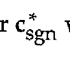
  • a sign-parity flag, sgnpar(c ) indicating odd or even parity of the binary sign vector is preferably stored at least for class-leader root-vectors of category B.
  • a distribution of signs ⁇ j indicating number of negative signs to transform a class- leader root into a class-leader vector is transferred from the encoder to the decoder over the communications channel as need be.
  • the index subspace could then be subdivided in relation to, e.g., W 1 , such that an index offset of an integer multiple of three corresponds to a different sign distribution of the w Q positions.
  • the index processing preferably subdivides the index (sub-)space for each additional weight under consideration.
  • a particular value on a particular position of the sign distribution e.g. , does not precondition a restricted number of possible sign distributions considering the remaining positions, since all sign distributions are possible for category A.
  • all 12 sign distributions are possible for vectors of category A.
  • encoder and decoder preferably store weights, r ⁇ ; , and amplitudes, £ov class-leader root vectors of a root equivalence class J with weights for non-zero component amplitudes, .
  • the weights and amplitudes are stored in read-only memory, ROM.
  • Other non-limiting example storage media for the weights and amplitudes are random access memory, RAM, or magnetic or electro-magnetic storage devices for reading of amplitudes and weights into RAM, e.g. at startup. Of course, they may be communicated over the communica- tions channel at the expense of an increased load on the communications channel.
  • the stored weights and amplitudes are combined with a sign distribution where to provide an index from which the decoder is capable of reconstructing the quantized vector.
  • the decoder can be made to reconstruct the class-leader vector and the equivalence class from the index and pre- stored data.
  • a corresponding helping function is preferably defined for vec tors of category B, where n denotes a sign-parity constraint and is the weight distribution as for vectors of category A.
  • the helping functions, ; ⁇ ), correspond to the size of
  • the index space for sign permutations For category B vectors, it corresponds to the size of the index space for sign permutations given the sign-parity constraint ⁇ for the class-leader root-vector.
  • the helping function also corresponds to the number of class-leader vectors and equivalence classes that can be produced from the current class-leader root-vector, for category B preconditioned on the sign-parity constraint.
  • the preferred index processing of code vectors of category A, forming an example component (142) of figure 14 and adopting the principles of figure 12, is schematically illustrated in figure 17.
  • the target index, ⁇ and an iteration counter, k are initialized (171) and the weights preferably loaded into operational memory of a processing entity. For each iteration, the index is updated (172, 175). Preconditioned
  • the candidate for index is determined to 16.
  • the second iteration does not change the candidate index since 1 .
  • the index is finally determined to 17 from the previous candidate index and .
  • the preferred index processing of code vectors of category B is illustrated schematically in figure 18.
  • the target index, p and an iteration counter, k are initialized (181) and the weights W ⁇ preferably loaded into operational memory of a processing entity.
  • a parity flag is initialized (181) to the preferably pre-stored sign-parity ⁇ of the class- leader root-vector corresponding to the class-leader vector of the equivalence class.
  • the candidate for index is updated (182, 185).
  • the candidate index is updated by a sum of index (sub-)space sizes ) / where p * is adjusted candidate parity, adjusted for the parity of the various sign combinations corresponding to the various weights as illustrated above for the simplified example.
  • is the number of weights for non- zero component amplitudes
  • the adjustment is expressed in figure 18 as a summation modulo 2, indicated (182) by ⁇ for brevity even though t is not necessar- ily binary.
  • the candidate parity is updated in relation to the sign distribution and the next weight and sign combinations are considered (183) until all but one non-zero weight(s) have been considered (184).
  • denotes (183) a modulo-2 sum.
  • For the last update of the candidate parity it is preferably verified that s even, and an integer representing half of this amount increments the candidate index to form the final index for category B (185).
  • Figure 19 illustrates a block diagram of example equipment (191) according to the invention.
  • the equipment comprises an input (192) for inputting signals to be quantized or indexed, for which a block of data is represented by a vector x, and an output (193) providing signal codewords.
  • the output signal carries codewords or indices corresponding to input vector x, or a normalized vector of radius 1 and a radius.
  • a signal carrying code vectors is output (192) in one mode of operating an embodiment of the invention.
  • the equivalence class offsets i are preferably stored in read only memory, ROM, flash memory or other storage medium (195).
  • Processing circuitry (194) of the equipment (191) implements quantization as described above.
  • the processing circuitry implements indexing.
  • Class-leader root- vectors are preferably stored in memory or other storage medium (195) to improve decoding speed or reduce amount of communicated data, and the processing circuitry (194) accesses (196) the storage medium (195) and reads memory or storage content (197).
  • the processing circuitry also preferably accesses some random access memory, RAM, (194), (195) for its operations.

Landscapes

  • Engineering & Computer Science (AREA)
  • Computational Linguistics (AREA)
  • Signal Processing (AREA)
  • Health & Medical Sciences (AREA)
  • Audiology, Speech & Language Pathology (AREA)
  • Human Computer Interaction (AREA)
  • Physics & Mathematics (AREA)
  • Acoustics & Sound (AREA)
  • Multimedia (AREA)
  • Theoretical Computer Science (AREA)
  • Compression, Expansion, Code Conversion, And Decoders (AREA)

Abstract

The invention pertains to a method and apparatus of efficient encoding and decoding of vector quantized data. The method and system explores and implements subdivision of a quantization vector space comprising class-leader vectors and representation of the class-leader vectors by a set of class-leader root-vectors facilitating faster encoding and decoding, and reduced storage requirements.

Description

METHOD AND APPARATUS OF COMMUNICATION
Technical field
The technical field includes communications and signal processing. More particularly, the invention relates to a method and apparatus providing data processing of low complexity for spherical vector quantization, SVQ.
Background
Today's communications are to a great extent digital. They are both time discrete and discrete in amplitude, relying upon digital samples. Well-known examples of the technical development from analogue communications systems to digital communications systems are digitization for distribution of analogue telephony and the switch from vinyl records to audio compact discs, audio CDs in the 70's and 80's. Other examples have followed, such as portable digital audio players and digital television broadcasting.
For fixed analogue telephony, analogue speech is distributed in electrical signals over phone wires. When analogue telephone systems have been digitized, the speech is still carried in analogue electrical signals from the phone to a switch of the operator, where it is digitized so as to allow reconstruction within predefined requirements or criteria as regards distortion of the analogue signal. To provide required dynamics with a limited number of bits, the speech signal is compressed before the digitization providing a digital signal for distribution. The compressors provide signals of reduced dynamics but are essentially lossless, since the analogue signal could be expanded in a receiver. This compression is known as A-law or μ-law compression. At the receiving end, the signal is then expanded. Today there are also fixed telephone systems being digital all the way from one phone to another. In this descrip- tion, compression is used for referring to lossy or lossless compression.
As regards CDs, analogue samples of time-continuous sound are quantized into a fixed number of bits (16 bits) with no compression of the quantized data. The limita- tion of sound samples to fixed levels provides some difference between the digitized samples and the analogue samples. TTiis is known as quantization noise or distortion. Since the number of quantization levels is great (216 ), the distortion is negligible compared to the noise produced in analogue components of most audio CD players or amplifiers and loudspeakers.
As regards portable audio players and video broadcasting, the requirement on reducing the number of bits required for storage or transmission while not requiring too complex equipment requiring a huge amount of storage or power for feeding extremely fast (and power consuming) computers. Today, portable digital audio play- ers and set top boxes for TV reception are available to many of those households that want them due to achievements of the technical development as regards, e.g., coding, storage media, such as flash memories, and computational capacity. Digital content stored on most portable digital audio players or broadcast in digital television or sound radio systems is compressed by lossy compression.
A communications channel may include media such as electromagnetic storage, electronic memories, propagation of signals in traveling waves of electromagnetic fields from a transmitting antenna to a receiving antenna, or propagation of optical signals from an optical transmitter to a receiver for optical signals.
Telephone systems, CDs, digital portable audio players and television broadcasting all provide examples of communications over a communications channel. The fixed wire provides a communications channel for the telephone system, the CD for the distribution of audio from a studio to a listener via a CD player,' the flash memory or other storage medium for the portable audio player or the radio channel for television broadcasting.
R.M. Gray and D.L. Neuhoff, "Quantization," IEEE Transactions on Information Theory, 1998, vol. 44, no. 6, pp. 2325-2383, traces the history of quantization from its ori- gins, starting from 1898, and survey the fundamentals of many of the popular and promising techniques for quantization.
Gray and Neuhoff refer quantization to "the division of a quantity into a discrete number of small parts." As an example, any real number can be rounded off to the nearest integer. In binary computing, integers are commonly represented by sequences of binary digits, bits, thereby providing a binary representation of the quantized real number. Other example data representations exist as well.
Quantization and source coding have their origins in pulse code modulation, PCM, the system used for audio CD recording. A PCM system consists fundamentally of three components: a sampler (11), a quantizer (12) and an encoder (13) as schematically illustrated in figure 1. Sampling converts a continuous time waveform (14) into a discrete time waveform (14). Quantization (12) of the samples (15) renders the quantized samples (16) to be approximations of the unquantized samples (15). The quantized samples, or indices thereof, are transmitted on a communications channel (17) as provided by the encoder (13). With scalar quantization, SQ, each (quantized) sample is independently encoded into a fixed number of bits, and correspondingly decoded into a reproduction. For a given distortion or reconstruction error, scalar quantization generally requires comparatively greater data rates than vector quantization, VQ.
Vector quantization, VQ, quantizes a number of samples simultaneously. VQ provides significantly higher quantization performance than scalar quantization, SQ, in the case of a fixed bit rate. In case of k successive samples to be quantized, VQ , makes use of a k-dimensional partition or a fc-dimensional codebook, C, comprising lc-dimensional code vectors, each code vector representing a cell of vectors with mini- mum distortion according to a predefined criterion, such as minimum Euclidean distance. For this purpose it is convenient to consider the quantization and encoding to be tightly related or one concept as schematically indicated by a dashed line (18) in figure 1. An advantage of VQ as compared to SQ is that it inherently can exploit memory of source signals to be quantized/ source signals such as the discrete time sequence (14) of the sampled waveform. Thereby, source signals such as speech signals or image signals commonly comprising memory or dependencies between different samples can be represented more efficiently. Also VQ comprises merits on its own and7 in principle/ SQ cannot perform better in terms of distortion versus rate than the best VQ. In prior art, the price for this improvement has been paid by increased complexity of, particularly, the encoder.
Figure 2 illustrates a simplified block diagram for vector quantization. A signal sequence (285) is represented by vectors (281) and signals (286) carrying the vectors are mapped (282) into an index (287) corresponding to a representation or codeword of the codebook/ a code vector, providing a minimum distortion encoding of the vectors (286) according to a predefined criterion or measure, e.g. Euclidean distance. The vector to be represented (288) and the quantized vector or a representative thereof (289) are exchanged between the minimum distortion determining entity (282) and the entity comprising the code book representation (283). At the output of the channel (at a receiving end) the reconstructed vector is achieved by using a similar code- book and looking up the code vector represented by the received index.
Essentially, transmission on a communications channel comprises all technical arrangements for distributing or communicating a signal from a source sender to a destination as schematically illustrated in figure 3. A sequence representing a code index (34, 35) is transmitted through a communications channel (32) to the destination where it is decoded in the receiver (33). From the viewpoint of a source encoder and decoder, the channel may be considered to comprise channel coding as need be to transmit or detect errors on a transmission channel. In practice, though, channel encoders and decoders separated from the source encoding and decoding are included in physical transmitters and receivers, respectively. So, from the viewpoint of the source encoding, also parts of physical transmitters and receivers are frequently included in the communications channel (32). For low bit rates, a good way to design a vector quantizer, from a rate distortion perspective, is to adapt the quantizer to characteristics of a given input source, e.g. provided in training sequences. Figure 4 illustrates schematically a flowchart for iteratively determining a codebook Y according to a generalized Lloyd algorithm, frequently referred to as an LBG algorithm (as disclosed by Y. Linde A. Buzo and R. Gray). The algorithm is initiated (41) by initializing a counter m, an initial codebook Y0 , a maximum possible (within the applicable range of the application) distortion
D_2 and a precision level ε. For each iteration, m, a partitioning Sm defining the cells surrounding the various code vectors of the code book, is determined (42) for the code book Ym , and the distortion Dm is determined (43). The algorithm is interrupted (44) when the relative distortion is smaller than the precision set initially. In case the relative distortion is greater than the preset level, ε, a refined codebook is determined, the iteration counter is updated (46) and the process repeats for another iteration starting with determining a partitioning for the refined codebook (42).
The LBG algorithm is commonly considered to be computational expensive in terms of number of instructions when there is a great number of quantization levels. It is also sensitive to the initial choice of codebook (41). Also the amount of read-only memory, ROM, required by a trained vector quantizer is usually considered to be too large. Another problem is related to the LBG algorithm being trained to provide minimum distortion for a particular training data sequence. If data from another source with substantially different statistical properties is quantized, the performance is most often suboptimal. For vectors of dimension 1, the LBG quantizer reduces to the scalar Lloyd-Max quantizer.
For high bit rates, the theory of VQ provides a method for creating a codebook providing the smallest distortion, e.g. in terms of Euclidean distance or squared Euclidean distance, given a certain statistic of the input signal based on the calculation of a point density function from the probability density function, PDF, of the input signal. Structured codebooks do not exploit linear or non-linear dependency to increase the quantization performance that vector quantizers are generally capable of. At least linear dependencies, however/ can be transformed to provide a benefit in quantization performance by means of Linear Prediction or Transform Coding. Therefore, the structured vector quantizers are designed such that they have high performance for memory less sources.
A lattice vector quantizer is a vector quantizer of which the codebook is composed of vectors which are arranged in a regular lattice according to a mathematical rule. A degenerate example lattice quantizer is a uniform scalar quantizer for the special case of a vector quantizer of dimension LΌ=1 . Lattices in higher dimensions benefit from a more efficient space filling. In other words, a lattice, Λ, comprises all vectors in an Lv dimensional vector space with
Figure imgf000008_0001
where % denotes integers, and E denotes real Lv -tuples. The vectors
are the basis vectors of the lattice, and all lattice vectors are
Figure imgf000008_0003
linear combinations of these basis vectors. The factors Λy to weight each basis vector are integer numbers. A lattice in general is a subset of an Lv -dimensional vector space but consists of a countable infinite number of points,
Figure imgf000008_0002
The number of weighting factors Λ,- determines the lattice's degree of freedom and is also called the dimension of the lattice
Figure imgf000008_0004
can be greater or smaller than lv. In most cases, the dimension equals the dimension of the vector space in which the basis vectors are defined,
Figure imgf000008_0005
For the case that the dimension of the lattice equals the dimension of the code-vector space, equation 1 is equivalent to a representation including a generator matrix M,
Figure imgf000009_0001
where the factors λj as before are integer weight factors and Lv is the dimension of the vector space. When more than one matrix provide the same distribution of points considering all λ in equation 3, they are all generator matrices of one and the same lattice.
Figure 5 illustrates an example two dimensional hexagonal lattice and corresponding basis vectors forming the generator matrix M. There are four vectors (51, 52, 53, 54) depicted. Vectors [
Figure imgf000009_0002
] [ (52) span the same set of points as do
basis vectors and
Figure imgf000009_0006
Figure imgf000009_0007
An example generator matrix providing the lattice is consequently
Figure imgf000009_0003
Another example generator matrix of the lattice is
Figure imgf000009_0004
An alternative, but equivalent, definition of the two dimensional hexagonal lattice, also referred to as the A2 lattice, in figure 5 is
Figure imgf000009_0005
Jacques Martinet, "Perfect Lattices in Euclidean Spaces," Springer-Verlag, Berlin, 2003, pp. 110-114, defines lattices of prior art such as the hexagonal lattice, A , and its dual,
, the checkerboard lattice, , and its dual , and the integer lattice, , for
Figure imgf000009_0009
Figure imgf000009_0008
arbitrary dimensions Lv . In the sequel, the printing symbol asterisk will be used for other purposes than for denoting a dual lattice.
Other known lattices are the Gosset lattice,
Figure imgf000010_0004
, the Coxeter-Todd-Lattice, K12 , the Barnes-Wall lattice A16 , and the Leech Lattice A .
Figure imgf000010_0005
A permutation code
Figure imgf000010_0010
defines all vectors of a codebook by means of class-leader vectors, , of dimension
Figure imgf000010_0009
. A class-leader vector
Figure imgf000010_0012
is composed of coordinate entries ^comprising components taken from a set o real val
Figure imgf000010_0008
Figure imgf000010_0013
Figure imgf000010_0011
ues
Figure imgf000010_0007
p, sorted in decreasing order
Figure imgf000010_0006
Figure imgf000010_0002
u>ι is the weight related to real value μ; and is the number of occurrences of real value μlf 0 < K Lτ,
Figure imgf000010_0003
1=0
A permutation of a class-leader vector is a vector that is composed of the same
Figure imgf000010_0015
Figure imgf000010_0016
real values, as but in a different order. The corresponding permutation
Figure imgf000010_0017
operation can be specified by means of matrix, P, referred to as the permutation matrix. The relation between and ψ could then be expressed as
Figure imgf000010_0014
Figure imgf000010_0001
An example permutation vector reversing the sequence order is
Figure imgf000011_0002
The permutation processing is preferably realized in a digital signal processor, DSP, adapted for the permutation of interest. High speed applications may require the permutations to be implemented in hardware, which can be achieved by employment of e.g. shift register circuitry. Reversal of sequence order is e.g. achieved by storing the vector components in a shift register of the same length as the vector, in component- wise sequential order, and feeding out the shift register content in the reverse order. This is illustrated in figure 6. The example shift register is composed of a number of D latches (601- 603). The vector to be reversed is input (604) to the shift register through closed switches (605-607) during a sequence of clock cycles during which one component of the vector is input after another. When the entire vector has been shifted into the D elements (601- 603), the previously closed switches (605-607) are being opened, and switches (608-610), previously open while shifting the vector into the register, are being closed. During the next clock cycles, the components are shifted out of the shift register (611) in reverse order. Effectively, the shift register of figure 6 could be replaced by memory circuitry or a storage medium for storing controlled by a signal processor. The corresponding processing comprises storing the vector components in the memory or storage medium and reading out the memory content or stored content component wise in the reverse order.
Given a class-leader vector and corresponding weights Wj , the number of possible permutations is
Figure imgf000011_0001
Ny is known as the multinomial coefficient. To identify one among all possible permutations/ a vector index , is useful for describing and
Figure imgf000012_0005
understanding the encoding process and mapping of code vectors. Since all permuted vectors are composed of the same coordinate values but in different order, the absolute value, or length, of the code vectors is identical for all permutated vectors. Using the vector index, this is
Figure imgf000012_0001
The Ny permutations of the class-leader vector altogether form a permutation code-
Figure imgf000012_0002
A further issue in the quantization process relates to compaction or how to represent the various vectors with fewer class representatives, such that the errors introduced by information loss due to the compaction will be acceptably small, or at best not be noticeable, to a user.
One representation of a vector x based on the class-leader vector, x y of a permutation code that provides the minimum Euclidean distance is achieved as follows. For a vector x of dimension
Figure imgf000012_0006
to be (further) quantized or compacted, permute the vector coordinates such that the components of the permuted vecto are ordered in decreasing order
Figure imgf000012_0004
Figure imgf000012_0003
The required permutations are represented by a matrix The ordered
Figure imgf000012_0007
vector x* is represented by a class-leader vector as specified in equation 7 and that also has its components sequentially ordered according to magnitude. For reconstructing x from x*, the process is reversed
Figure imgf000013_0002
x The matrix
Figure imgf000013_0003
also provides a minimum Euclidean distance representative for the vector x to be
Figure imgf000013_0004
quantized or compressed.
Figure imgf000013_0001
To achieve the compression a vector index, iγ, is determined for the vector representative
Figure imgf000013_0005
This is achieved by a permutation to index mapping and which is preferably achieved by a mapping suggested by J. Pieter and M. Schalkwijk.
The mapping consequently transforms the permuted vector
Figure imgf000013_0006
into an index
Figure imgf000013_0007
. A decoder realizes the reverse operation and maps the index
Figure imgf000013_0008
p back into a permuted
vector , corresponding to the original permuted vector. Consequently, there is a
one-one mapping between permuted vector and index the index iψ providing
Figure imgf000013_0009
Figure imgf000013_0010
a representation of the permuted vector suitable for transmission, storage or fur
Figure imgf000013_0011
ther processing such as for channel encoding. In brief, the index is suitable for transfer on a communications channel. The number of indices, is equal to the
Figure imgf000013_0012
number of possible permutations,
Figure imgf000013_0013
(see equation 11).
US Patent No. 4075622 describes a method and apparatus for data compression which utilizes a random walk through Pascal's triangle directed by an incoming binary source sequence. The random walk starts at the apex of Pascal's triangle and proceeds downward according to an algorithm until it terminates at a boundary which has been constructed in such a way that the encoding of each source sequence can be accomplished in a fixed number of bits.
LfS Patent No. 6054943 describes a variable-to-block universal multilevel digital information compression making use of a random walk in Pascal's hypervolume, a multi-dimensional generalization of Pascal's triangle. Codewords and decoded source sequences are either determined in the encoder and decoder, respectively, on the fly at encoding/decoding or pre-computed and stored. Variable length sequences of source symbols are encoded into fixed length codeword blocks. Encoders and decoders including dedicated hardware including registers, counters and latches are disclosed as are flowcharts. Figure 26 of US6054943 illustrates graphically an example encoding (and decoding) of an example sequence of a ternary source. Depending on the source sequence and for each incoming source symbol, a particular candidate prefix is selected and a running sum is updated. The final value of the running sum, rs, for a sequence of symbols orresponds at least to a part of an index or
Figure imgf000014_0006
codeword and equals
Figure imgf000014_0001
where is the incoming symbol at stage k and where the summation is
Figure imgf000014_0005
over all n incoming symbols and is the number of symbols that have
Figure imgf000014_0004
Figure imgf000014_0003
arrived after k stages. The outer sum is determined recursively by adding the inner summation for each incoming symbol to encode. The encoding is terminated at a particular element in Pascal's hyper volume. This point is added as a starting point prefix for the decoder to know where to start tracing back in Pascal's hyper volume. It is also suggested in US6054943 to add a prefix to allow uncoded transmission in order to avoid encoder expansion to happen for some sequences. At encoding, a recursion for determining the running sum for an incoming symbol ;' is
Figure imgf000014_0002
where oldPos is the old position in Pascal's hyper volume. The position in Pascal's hyper volume is similarly updated recursively for the next iteration,
Figure imgf000015_0001
where I corresponds to the number of symbols that have come in.
The recursion for decoding works the path through Pascal's hyper volume for choos- ing a symbol / that provides a position that is not greater than a candidate for the corresponding position in the hyper volume. The recursion for the running sum in reverse direction, decoding position / of a codeword, in US6054943 is
Figure imgf000015_0002
with the associated recursions decoding next
Figure imgf000015_0003
Khalid Sayood, "Introduction to Data Compression, 2 edition, 2000, pp. 290, 291" pro- vides a first introduction to spherical vector quantizers. For the Gaussian probability distribution, the contours of constant probability are circles in two dimensions. In two dimensions an input vector can be quantized by transforming it into polar coordinates comprising radius, r, and phase, θ. Polar coordinates span the same space as do Cartesian coordinates, r and θ can either be quantized independently, or quan- tized values of r can be used as an index to a quantizer for θ. The advantage to quantizing r and θ independently is reduced complexity as compared to a quantizer for which the quantization of θ depends on the quantization of r. As mentioned above in relation to scalar quantizers, not making full use of interdependencies within a block tend to reduce performance.
Jon Hamkins, 'Design and analysis of spherical codes/ Thesis submitted in partial fulfillment of the requirements for the degree of Doctor of philosophy in Electrical Engineering in the Graduate College of the University of Illinois at Urbana-Champaign, dated 1996, briefly defines and provides properties of the root lattices nd their duals in
Figure imgf000016_0002
chapter 2, the "root" relating to the root systems of certain Lie algebras. Hamkins also defines a codebook as a set of output points or vectors forming the code points or code vectors. A /:-dimensional spherical code is defined as a finite set of points in
Figure imgf000016_0003
that He on the surface of the k-dimensional unit radius sphere
Figure imgf000016_0004
^
Figure imgf000016_0001
In chapter 6, Hamkins describes wrapped spherical codes as vector quantizers for a memoryless Gaussian source and provides an algorithmic description of an encoder in table 6.1 quantizing gain and shape of a vector independently, the gain corresponding to the length or radius of the vector, and the shape corresponding to the vector normalized to 1. The gain codebook is optimized by the Lloyd-Max algorithm. Since the PDF is known (Gaussian source), no training is required. The algorithmic description is also included in Jon Hamkins and Kenneth Zeger, Gaussian Source Coding with Spherical Codes, IEEE Transactions on Information Theory, vol. 48, No. 11, pp. 2980- 2989 (2002).
Summary
In prior art technology, the number of class-leader vectors for representing source - data, e.g. speech, tend to be large, thereby requiring substantial storage capacity of e.g. codebook representation for encoding and decoding in digital communications equipment. A great number of class leaders requires a great time for determining the code vector in the encoding process in order to minimize distortion.
None of the cited documents provides a method or system of quantization or coding wherein a metric or distortion forming a criterion according to which a signal, or (us- ing vector notation) code vector or codeword, to output for an unquantized input signal, or vector, is determined from a reduced set of code vectors of an E-lattice being linked to the (full) set of code vectors by a sign distribution.
In communications in general and in today's digital communications in particular, it is a challenge to provide communications resources meeting increasing amounts of data being communicated at an increasing rate while providing communications services at a decreasing cost. One crucial element for making digital communications financially and technically possible to a great number of people is efficient quantization of data for efficient signaling. Speech encoding and decoding for speech communications in mobile telephone systems, sound encoding for storage of songs and decoding for reproducing the sound in portable audio players or surround sound equipment reproducing movie sound, or other multi-channel sound, stored on a DVD or CD or received from public broadcasting companies by wire or over the air and image coding and decoding for digital television are some communications examples well known to the public.
For further development, it is a challenge to reduce complexity or storage requirements for a given code, or maintain complexity or storage requirements while allowing more complex coding principles, and there is a need of improved encoding and decoding efficiency.
Consequently, it is an object of example embodiments of the invention to provide re- duced processing or storage requirements compared to processing required for a representation based on a set of class-leader vectors compared to today's requirements for given codes. It is an object of a preferred example embodiment of the invention to determine a quantization output from a reduced set of code vectors providing the same metric/distortion and output as if determined from the full set of code vectors.
It is also an object of example embodiments of the invention to allow for more com- plex encoding and decoding without increasing cost or complexity of encoders or decoders.
Further, it is an object of an embodiment of the invention to allow quantization or coding of signals being less restricted to particular block lengths, corresponding in vector notion to the dimension of the vector space.
It is an object of an embodiment of the invention to provide signals or signaling representation by sub-division of a codebook facilitating a one-one representation of class-leader vectors (using vector notation) with a (smaller) number of vectors suitable for storage in electronic, magnetic or optic storage media or representation for communication signaling.
Further, it is an object of a preferred embodiment of the invention to provide associated indexing for communication on a communications channel.
The invention provides a method and system implementing sub-dividing a set of class-leader vectors of a vector quantization encoder or decoder for encoding and decoding of communications data and mapping of corresponding data as described in detail below in relation to encoding and decoding processes.
Brief description of the drawings
Figure 1 schematically illustrates a sampler, a quantizer and a coder according to prior art.
Figure 2 illustrates a simplified block diagram for vector quantization according to prior art. Figure 3 illustrates schematically transmission on a communications channel according to prior art.
Figure 4 demonstrates schematically a flowchart for iteratively determining a code- book according to a generalized Lloyd algorithm of prior art.
Figure 5 illustrates an example two dimensional hexagonal lattice in prior art.
Figure 6 depicts a block diagram of an example shift register according to prior art.
Figure 7 shows a basic block diagram for parallel quantization of a radius and a normalized vector according to prior art.
Figure 8 shows a basic block diagram for serial quantization of a radius and a normalized vector according to an example mode of the invention.
Figure 9 plots an example distribution of code vectors according to the invention.
Figure 10 illustrates a flowchart of an efficient quantization procedure according to the invention.
Figure 11 illustrates schematically sub-ranges corresponding to equivalence classes in relation to root-vector classes for a simplified example according to the invention.
Figure 12 displays a flowchart illustrating example indexing in an embodiment of the invention.
Figure 13 depicts a basic flowchart for quantization according to an embodiment of the invention.
Figure 14 shows a simplified flowchart for determining a transformed distortion metric according to a preferred embodiment of the invention.
Figure 15 illustrates schematically indexing providing codewords from quantized data according to an embodiment of the invention. Figure 16 illustrates schematically a flow-chart of a preferred decoder according to the invention.
Figure 17 displays schematically preferred index processing of code vectors of category A according to the invention.
Figure 18 illustrates schematically preferred index processing of code vectors of category B according to the invention.
Figure 19 monitors a simplified block diagram of example equipment according to the invention.
Detailed description Vector quantizers based on structured codebooks generally provide a good compromise between memory requirement, computational complexity and quantization performance for practical use. For a given input signal probability distribution function, " PDF, the theoretically optimal code-vector point-density-function for a given input signal PDF is well approximated by structured codebooks such as lattice codebooks and permutation codebooks. These codebooks are not stored completely in memory and are searched efficiently for codebooks according to the invention.
Knowledge on the probability distribution function, PDF, is required for the structured codebooks. It is not useful to assume a certain (statistical) characteristic of audio signals. Worst case assumptions are preferably made so that the designed VQ has good performance even for the signal that is hardest to quantize. Among all signal characteristics, Gaussian noise has the highest differential entropy. Therefore, following the worst case approach, a quantizer for audio coding should preferably be designed to have good performance for Gaussian sources.
Spherical vector quantization, SVQ, is a quantization that approximates the optimal code-vector point-density for the Gaussian distribution and at the same time can be realized efficiently. If properly designed, the achieved signal to noise ratio, SNR, re- lated to SVQ is independent from the PDF of the input signal and from the dynamics of the input signal for a wide dynamic range.
In the course of the quantization process, an example input signal representing an input signal vector, x, is transformed into a signal representing a radius,
Figure imgf000021_0003
of
the vector, x, and a normalized vector Both the radius and the normalized
Figure imgf000021_0002
vector will be quantized to produce a quantized radius, / and a quantized
Figure imgf000021_0001
normalized vector with the codebooks for the radius and for the
Figure imgf000021_0004
Figure imgf000021_0006
Figure imgf000021_0007
normalized vector. In the sequel is referred to as a spherical code vector
Figure imgf000021_0005
and as the codebook for the spherical vectors. If the radius is quantized by
Figure imgf000021_0008
means of logarithmic quantization, e.g. A-law quantization well known from compression of PCM in telephone systems, the quantization signal to noise ratio, SNR/ is independent of the probability density function of the input signal. This is also referred to as logarithmic SVQ.
The quantized output signal vector is
Figure imgf000021_0009
Figure 7 shows a basic block diagram for parallel quantization of a radius (72) and a normalized vector (73). The radius and normalized vector are quantized independently. Both the block (71) separating the radius and the spherical vector and the quantizers (72), (73) are preferably included in an encoder entity, whereas the combining entity (74) is preferably included in a decoder entity. The output signal repre- senting an output vector, x, of the combining entity (74) is the reconstructed value of the input signal represented as input vector x. The figure does not include processing equipment of index determining for reasons of simplicity. Signaling carrying codewords corresponding to indices are preferably transferred on a communications channel. Accordingly, the invention preferably includes processing equipment for index determining.
Figure 8 shows a basic block diagram for- serial quantization of a radius (82) and a normalized vector (83). As for the parallel quantization, both the block (81) separat- ing the radius and the spherical vector and the quantizers (82), (83) are preferably included in an encoding entity, whereas the combining entity (84) is preferably included in a decoder entity. In contrast to the parallel realization the radius quantization is performed after the quantization of the normalized vector, c. This will allow for considering the curvature of the quantization cells, which is effective particularly for large cells. Especially for low bit rates, the sequential approach provides a slightly higher performance. The output signal representing an output vector, x, of the combining entity (84) is the reconstructed value of the input signal represented as
input vector x. The figure does not include index determining for Rx or x , respectively. In similarity with the parallel quantization, an encoder preferably comprises equipment for determining one or more indices. Signaling carrying codewords corresponding to indices rather than quantized vectors are preferably transferred on a communications channel.
Figure 9 plots an example distribution of code vectors, indicated by black points (91), (92), (93), of spherical vector quantization with quantization cells (94), (95) corresponding to parallel quantization for LΌ=2 and signal vectors • The
Figure imgf000022_0001
code vectors are located on the surface of spheres, which for the 2-dimensional case are circles. The radii differs for code vectors on different circles (92), (93).
There are different encodings for representing the quantized vectors (code vectors). The scalar radius quantizer, QR , (72), (82) is preferably realized by electrical circuitry implementing a lookup table, since the number of quantization and reconstruction levels is usually modest and, consequently, the number of entries required to be stored is small, particularly if logarithmic quantization is applied. For the serial quantizer in figure 8, the quantization process is, e.g., realized by processing circuitry implementing a bisection based on a table containing all interval bounds. The sequential combination of the quantizers is referred to as re-quantization of the radius.
Denote a quantized vector (code vector) as . The index
Figure imgf000023_0004
of the code vector
Figure imgf000023_0005
Figure imgf000023_0003
denotes required and sufficient information to reconstruct the code vector in the decoder. Considering, e.g., logarithmic SVQ, there are two indices,
Figure imgf000023_0002
corresponding to the selected quantization reconstruction levels of the radius and the quantized normalized vector, respectively. There are two modes of combining the indices into a single index in the invention. The former is preferred due to a small advantage for transfer over communication channels introducing channel errors. They are
Figure imgf000023_0001
where N is the number of code vectors for the normalized vector and NR is the number of available quantizer reconstruction values for the radius.
A Gosset Low Complexity Vector Quantizer according to an embodiment of the in- vention is based on code vectors from a lattice derived from the well known Gosset lattice, E8 . The E8 lattice is known to have the highest possible density of points in eight dimensions. The invention identifies advantages as regards encoding and decoding that can be achieved based on a generalized Gosset lattice, E-lattice. Thereby efficiency gains as regards computational complexity and memory/storage require- ments are achieved.
The Gosset lattice was originally designed for eight dimensions, . In order not
Figure imgf000023_0006
to limit the invention to LΌ=8 , the E-lattice (to be further explored as will be explained below) is generalized in the invention from the Gosset lattice to an arbitrary dimension L0 as follows E LV " D LV U OVv) : v= [% ...%] , eq. 25
Figure imgf000024_0002
where
Figure imgf000024_0001
is the checkerboard IaWiCe7 or D-lattice, of the same number of dimensions, LΌ , as the
E-lattice. The well-known modulo operation provides the remainder, so that (modulo 2) refers to the remainder when dividing by 2.
Lattice vectors with a same distance to the origin define a shell, S , of the lattice. To simplify notion/ for the generalized Gosset lattice/ or E-lattice, E^ , a shell with a
Figure imgf000024_0007
squared distance to the origin equal to
Figure imgf000024_0008
2M is denoted
Figure imgf000024_0005
S (ELV' . The radius of the
particular shell of the E-lattice is denoted R^E^ . Consequently, the shell is defined
Figure imgf000024_0006
as
Su(E^h-y - {^ \\ - \\ →u{E°} - eq.27
Figure imgf000024_0009
Each E-lattice spherical vector codebook
Figure imgf000024_0010
, X ^ 1^ K is composed of all vectors related to a specific shell of squared radius Iu , normalized to radius 1,
Figure imgf000024_0011
The effective bit rate of the E-lattice is
Figure imgf000024_0012
where N0^o ^ is the number of code vectors located on a shell with radius \
Figure imgf000024_0004
j2u of
∑l . The number of code vectors, Ns£ ^ \ located on the various shells of Ej^ de-
Figure imgf000024_0003
pends on the radius
Figure imgf000025_0001
/ and the particular E-lattice. Table 1 lists the number of code vectors versus half the squared radius for the well known Gosset lattice, Es . Also included in the table is the respective effective bit rate to address the code vectors of the shell.
Given a specific effective target bit rate per sample for the spherical codebook, reff Sp, shells of successively greater radii of the lattice of interest are investigated one by one, starting with a shell of smallest radius, i.e. smallest natural number u, when constructing the codebook. The codebook is finally based upon a shell wSp , with as many code vectors as possible provided that the effective bit rate per sample does not exceed the effective target bit rate per sample,
Figure imgf000025_0002
where denotes natural numbers.
Figure imgf000026_0011
Table 1: Number of code vectors on different shells of the Gosset lattice.
For reasons of simplicity/ a codebook for encoding and decoding according to the invention based on a particular E-lattice is also referred to by the particular shell or by the half of its squared radius, .
Figure imgf000026_0010
The E-lattice is invariant under an interchange of vector coordinates. AU spherical code vectors can be grouped into a number, M of equivalence classes,
Figure imgf000026_0008
Figure imgf000026_0009
Each equivalence class is composed of vectors generated by a
Figure imgf000026_0001
permutation code given the class-leader vector Hence, the spherical vector
Figure imgf000026_0007
Figure imgf000026_0006
codebook can be expressed as a superposition of codebooks, Xφ ,
Figure imgf000026_0004
Figure imgf000026_0005
Figure imgf000026_0003
of a permutation code Tm,
M (%U
X (EL 0) = I ) X -P. eq. 31
TIl m=0
Figure imgf000026_0002
The respective number of equivalence classes related to spherical codebooks of different shells with half squared radius ..., 10 are listed in table 2.
With the decomposition of the E-lattice spherical codebook into equivalence classes and the quantization procedure related to permutation codes, an efficient quantiza- tion procedure according to the invention is as follows and as also illustrated in the flowchart of figure 10.
For a normalized vector c to be quantized, reordering corresponding to a permutation matrix Pc is determined such that when applied to the normalized vector, the coordinates of the vector are rearranged in decreasing order (101). The permuted vector
Figure imgf000027_0003
s
Figure imgf000027_0001
where
Figure imgf000027_0004
Class-leader vectors are usually pre-stored in read-only memory or other storage medium. From the set of all the class-leader vectors, SE
Figure imgf000027_0005
candidate
Figure imgf000027_0002
g [ is, e.g., searched and selected (102) by processing
circuitry from the equivalence classes that out of the stored
Figure imgf000027_0006
class leader vectors, provides minimum distortion with respect to the (unquantized) vector c , according to a predefined criterion, such as minimum squared Euclidean distance,
Figure imgf000027_0007
Since the vectors and are of fixed (normalized) length, minimizing distor-
Figure imgf000027_0008
Figure imgf000027_0009
tion in equation 33 is equivalent to maximizing the correlation or scalar product of the vectors
Figure imgf000028_0001
The spherical code vector preferred to represent c is determined (103) by processing the class-leader vector representative corresponding to applying the inverse of the permutation matrix
Figure imgf000028_0004
Hence, the spherical code vector determined to represent the normalized vector c is
Figure imgf000028_0002
The quantized vector c is mapped (104) to a codeword, or index, in digital sig
Figure imgf000028_0005
nal processing equipment. This is preferably achieved by applying the Schalkwijk algorithm/ well-known in the art, to the particular code of the invention as follows.
Given more than one permutation code, in the range of all possible indices respective sub-ranges (111), (112), (113), (114) corresponding to
Figure imgf000028_0006
the equivalence classes and are determined as schematically
Figure imgf000028_0007
Figure imgf000028_0008
Figure imgf000028_0009
illustrated in figure 11, for the example case of four equivalence classes. The example sub-ranges are not uniform. Index offset corresponding to the sub-ranges,
Figure imgf000028_0010
included in figure 11 for are preferably stored
Figure imgf000028_0011
Figure imgf000028_0012
for each of the sub-ranges (111), (112), (113), (114) to speed-up encoding or decoding and then need not be transferred on the communications channel.
For the sub-range (111), (112), (113)y (114), corresponding to equivalence class
Figure imgf000028_0014
digital signal processing equipment determines an index in analogy with prior art
Figure imgf000028_0013
methods. Thus, the desired index of the quantized vector c is determined in the signal processing as
Figure imgf000028_0003
The determining of the index
Figure imgf000029_0006
γ is described in brief as follows. For an index range
Xp , the number of indices is
Figure imgf000029_0005
p. Assume that then coordinates remain
Figure imgf000029_0007
Figure imgf000029_0008
to be determined, i.e. to be associated to a specific value . The number of possible
Figure imgf000029_0009
permutations for the remaining sub-vector is calculated from the number of permutations in equation 11 with adjusted weights
Figure imgf000029_0004
v
Figure imgf000029_0001
For each choice of h, the number of possible permutations of the sub-vector compris¬
ing the remaining vector components defines a sub-range of indices, provide
Figure imgf000029_0011
This sub-range is denoted Thereby, the index range is sub-divided into
Figure imgf000029_0012
Figure imgf000029_0010
sub-ranges
Figure imgf000029_0003
The number of indices in a sub-range associated with a particular value μ^. is
Figure imgf000029_0002
The sub-ranges are further sub-divided into smaller sub-ranges, and at last there is a single index.
Figure 12 displays a flowchart illustrating an example indexing as explained above for encoding of a sequence for communication over a communications channel. Indexing is initialized (121), where wt( ) denotes the weight or the number of occurrences of a particular symbol. The rank of an incoming symbo is determined (122)
Figure imgf000029_0013
and the index is updated accordingly by the sum of number of indices in correspond- ing sub-range (123). The weights are updated (124) and the recursion continues for the next incoming symbol (125) until the last symbol of the code vector have been encoded (126). The index then finally results from the last recursion (127).
The invention identifies that in many cases a great number of equivalence classes are involved depending on, e.g., dimensionality and sphere radius. As a non-exclusive example illustrated in table 2, the number of equivalence classes, 0 is
Figure imgf000030_0001
162. A brute-force implementation of the quantization process will/ for such cases, tend to require great memory and computational capacities in terms of number of bytes and number of operations per second, respectively.
Figure imgf000030_0003
According to a preferred embodiment of the invention, the requirements on the quantization equipment is substantially relieved by a quantizer implementing grouping of equivalence classes, Εm , in root classes
Figure imgf000030_0002
For the example radius corresponding to M=10, the number of classes is reduced from 162 to 11 for the Gosset lattice, or more than by a factor of 10, providing a load reduction in a corresponding order of magnitude, while providing identically the same codewords and distortion, e.g. in terms of minimum Euclidean distance. For the definition of the root classes consider two categories of code vectors, labeled categories A and B. Vectors of category A are in D and comply with the require¬
ment in equation 26 and vectors of category B are in and comply
Figure imgf000031_0008
with the requirement in equation 25. Consider a spherical code vector
Figure imgf000031_0010
, of category A, and denote it When changing the sign of a single coordinate position, e.g.
Figure imgf000031_0009
position J0 , the resulting vector is also a vector of category A, since
Figure imgf000031_0002
and the radius of the vector remains unchanged.
Consider a spherical code vector, c , of category B, and denote i
Figure imgf000031_0013
. When changing the sign of exactly two coordinate positions, e.g. positions and , the resulting
Figure imgf000031_0011
Figure imgf000031_0012
vector is also a vector of category B, since
Figure imgf000031_0003
and each vector of category B, can be expressed in terms of a vector comprising
Figure imgf000031_0005
integer components, , in as for y in equation 26 from the relation
Figure imgf000031_0006
Figure imgf000031_0007
while the radius of the vector remains unchanged.
Figure imgf000031_0004
According to the invention, a sign parity check sum for code vectors c, is defined.
Figure imgf000031_0001
where
Figure imgf000032_0003
It is observed that all class-leader vectors can be constructed from class-leader
Figure imgf000032_0005
root- vectors
Figure imgf000032_0001
where is the number of root classes,
Figure imgf000032_0004
each comprising one class-leader root-vecto . The required codebook
Figure imgf000032_0007
Figure imgf000032_0006
size, e.g., is substantially reduced by doing so for most codes based on E-lattices of practical interest. Also, the encoding complexity is reduced, since not all class leader vectors need to be searched during the encoding. According to the invention, preferably the class-leader root-vectors are searched. In the preferred embodiment, there is a small additional computational load due to searching for category-B vectors providing minimum distortion. A class-leader root- vector is composed of Ly
different values each occurring times, where also being referred to as
Figure imgf000032_0013
Figure imgf000032_0011
Figure imgf000032_0012
the weight of .
Figure imgf000032_0014
Similar to the class-leader vector in equation 7, the class-leader root-vector can be expressed as
^
Figure imgf000032_0002
where μ; >0 for all class-leader root-vectors. The respective number, of class-
Figure imgf000032_0008
leader vectors of a particular category equals the number of possible sign permutations related to the weights, , of non-zero coordinate values, for the class-
Figure imgf000032_0010
Figure imgf000032_0009
leader root-vector class. For a category A class-leader root-vector of equivalence class this number is
Figure imgf000033_0001
For a category B class-leader root-vector/ the number of possible sign permutations is considered for pair wise components in order to maintain sign parity. Accordingly, the respective numbers of sign permutations for the cases of even and odd sign parity are
Figure imgf000033_0002
The number of root classes for different shells of the Gosset,
Figure imgf000033_0003
are also listed in table 2.
As an example to demonstrate how to construct the class-leader vectors from the class-leader root-vectors, the class-leader vectors for a shell with radius 2 , corresponding to u=2 are included in table 3.
Figure imgf000034_0001
Table 3: Class-leader root-vectors and corresponding class-leader vectors, w=2.
In the application of lattice vector quantization, the number of code vectors is limited and only a limited set of the vectors constructed by the lattice rule is considered.
The computational burden of quantization processing is significantly reduced due to example embodiments of the invention as explained above.
Lattice vector quantizers in general are very well suited for quantization also for the reason that no explicit codebook has to be stored but could be determined from, e.g., its generator matrix. When lattices are used for generating a codebook, the codebook will be structured, thereby facilitating fast search for code vectors. In brief, lattice vector quantization is an efficient example of quantization. Figure 13 depicts a basic flowchart for quantization according to an embodiment of the invention. For a vector x to be quantized, it is preferably normalized to a vector c of radius 1 (131) to simplify subsequent processing. Each component of the (normalized) vector is separated into respective magnitude and sign to form a mag- nitude vector and a sign vector (132),
Figure imgf000035_0001
The magnitude vector is permuted to arrange the components in decreasing order (133),
Figure imgf000035_0002
and the sign vector is permuted accordingly (133),
Figure imgf000035_0003
Using component-wise notion, the permuted magnitude vector can also be written
Figure imgf000035_0004
A metric is usually considered a quantity to be maximized. However, this specification preferably refers to a quantity to be minimized, similar to a distance. The difference merely resides in a different sign. The negative distance is maximized when the distance is minimized. A distortion metric Dm- , preferably a Euclidean distance, is
determined for, preferably, each of the class-leader root- vectors, c^ <pm, , in relation to the permuted magnitude vector
Figure imgf000035_0006
134),
Figure imgf000035_0005
Similar to equations 33 and 34 and as an alternative to the distortion as expressed in equation 53, the correlation could be maximized. Equivalently, the negative correlation could be minimized, since the distortion measure in equation 53 equals
Figure imgf000036_0002
V V W / where Q is a constant corresponding to the lengths of vectors
Figure imgf000036_0005
^ and For
Figure imgf000036_0006
normalized vectors and consequently equals 2. The subsequent
Figure imgf000036_0003
Figure imgf000036_0004
processing conditionally depends on whether the selected class-leader root- vector is of category A or B and the distortion V determined initially, conditionally requires
Figure imgf000036_0007
to be transformed to correspond to the distortion of the class-leader vectors (135). The class-leader root-vector providing the least (transformed) distortion, $, is se-
Figure imgf000036_0008
lected for the output of the quantization processing (136).
Figure imgf000036_0001
Figure 14 shows a simplified flowchart for determining a transformed distortion metric. For a class-leader root-vector of category A (141), minimizing the distortion in equation 53 and corresponding to an equivalence class
Figure imgf000036_0009
, the class-leader vector which achieves the lowest distortion is determined by the sign distribution of the permuted sign vector which is identical to the sign distribution of the class-
Figure imgf000036_0010
leader vector. In this case, the distortion is the same for the class-leader vector as for the class-leader root- vector of category A (142). Consequently, transformation of distortion as determined for the class-leader root-vector is not required for vectors of category A (142),
Figure imgf000036_0011
For a class-leader root-vector of category there are two cases to
Figure imgf000036_0012
Figure imgf000036_0013
consider depending on sign parity of the permuted sign vector and the class-leader root-vector. In case the sign parities are identical (143), the calculated distortion does not require to be transformed (142), since it is the minimum distortion achievable by- all respective class-leader vectors and, consequently,
Figure imgf000037_0002
For case 1 and for the class-leader root-vector of category B providing the smallest distortion in equation 53, the class-leader vector has identically the same sign
Figure imgf000037_0005
distribution as the permuted sign vector (143), as was also the case for category
Figure imgf000037_0006
A above.
In case the sign parity of the permuted sign vector differs from sign parity of the
Figure imgf000037_0010
class-leader root-vector for a class-leader root- vecto of category B, case 2, the
Figure imgf000037_0008
sign of a coordinate of the class-leader root-vector differs from . Denote this
Figure imgf000037_0009
coordinate by
Figure imgf000037_0011
The transformed distortion then is
Figure imgf000037_0001
The permuted sign vector is corrected accordingly by increasing the permuted
Figure imgf000037_0012
sign- vector component in position
Figure imgf000037_0013
by 1 (modulo 2),
Figure imgf000037_0003
This operation corresponds to an XOR operation Φ inverting a sign bit in position
Figure imgf000037_0014
in a binary representation of
Figure imgf000037_0007
The position is determined from the minimum of the second term in the second equality of equation 58 corresponding to additional distortion,
Figure imgf000037_0004
As mentioned above, one or more indices are preferred to the code vector for information transfer on a communications channel. For this purpose, an indexing machine and related processing has been developed beyond previous work of e.g. Pieter and Schalkwijk.
Provided a permutation matrix P , a permuted sign vecto
Figure imgf000038_0005
and a root class
Figure imgf000038_0004
for which equation eq. 55 applies, the indexing is preferably performed as follows and schematically illustrated in the flowchart of figure 15 and implemented in processing equipment (191), (194) of figure 19.
- Determine (151) equivalence classes (111-113), (114) correspond-
Figure imgf000038_0002
ing to the selected root class 115), (116) as illustrated in example
Figure imgf000038_0003
figure 11 and table 3.
- Based upon the permuted sign vector , select (152) the equivalence
Figure imgf000038_0007
class , or equivalently its class leader, from the equivalence classes
Figure imgf000038_0006
corresponding to the selected root class as described above in relation to the flowchart of figure 13.
- Determine (153) index offset i of as illustrated in figure 11.
Figure imgf000038_0008
- Determine (153) a permutation index i with respect to matrix
Figure imgf000038_0010
Figure imgf000038_0009
preferably according to previous work of Pieter and Schalkwijk.
The quantization index codeword is then determined (154) as described in relation to equation 36 on page 26 considering permutation matrix Pc,
Figure imgf000038_0001
where the permutation matrix P c of the normalized vector c, output from, e.g., the indexing provided by Pieter and Schalkwijk, replaces P of equation 36. The offset s set in relation to the equivalence class of interest and is incorporated
Figure imgf000038_0012
Figure imgf000038_0011
in the inde for communication on the communications channel. In figure 11,
Figure imgf000038_0013
index range grouping in relation to example root-vector classes is demonstrated. In the example of figure 11, root class
Figure imgf000039_0006
represents example equivalence classes
Figure imgf000039_0004
and example root class J
Figure imgf000039_0005
corresponds to equivalence class
Figure imgf000039_0009
3 ( ) The equivalence class offsets and re also offsets
Figure imgf000039_0007
Figure imgf000039_0008
for the root classes J
Figure imgf000039_0002
7Q and J
Figure imgf000039_0003
7I, respectively. The equivalence class offsets i off ^- ,
1OfT £* ' z off 2b an<^ z off 2T^ are Preferably stored in read-only memory.
Figure imgf000039_0001
According to one embodiment of the invention, indexing of class-leader vectors is performed on the basis of the sign vector in equation 52. in equation 51 is
Figure imgf000039_0010
Figure imgf000039_0011
preferably indexed similarly, though is not necessarily binary, while is bi-
Figure imgf000039_0014
Figure imgf000039_0012
nary. For class leaders in category B, the sign vector with corrected position as
Figure imgf000039_0013
Figure imgf000039_0015
in equation 59 is preferably indexed.
Codeword representation by a class-leader root-vector in place of a plurality of class- leader vectors due to tine suggested sign separation and parity constraint provides substantial complexity reduction according to preferred embodiments of the inven- tion. Correspondingly, preferred embodiments of the invention provide reduced vector searches, searching an equivalence root class instead of searching a plurality of equivalence classes for a codeword providing least distortion.
The invention identifies the fact that the equivalence classes,
Figure imgf000039_0016
related to one equivalence root class,
Figure imgf000039_0018
, are based on vector components with the same amplitudes but with different signs. For an equivalence root class, J one of the equivalence
Figure imgf000039_0017
classes need be identified at the decoder to get information on the sign distribution.
The specific equivalence class is preferably determined by index comparison for the equivalence root class, the index range of which corresponds to the index range of one or more equivalence classes as illustrated in figure 11. For an incoming vector quantization index , preferably with assistance of stored index offsets , the class-leader root- vector that has been identified by the en
Figure imgf000040_0003
coder and a corresponding sign distribution index identifying the equivalence class leader are determined. After removal of offset, the resulting index, , is input to a
Figure imgf000040_0002
decoder, preferably operating in accordance with the suggestions of Schalkwijk and Pieter. From the class-leader root-vector and the sign distribution indicating negative vector components, the relevant information required by the decoder for determining the equivalence class-leader is available.
For all class-leader root-vectors, the weights W
Figure imgf000040_0004
and the amplitudes are
Figure imgf000040_0001
preferably stored without signs. The decoder then modifies/adjusts these values in accordance with the sign adjustments in equation 59 from the sign distribution of the decoded index as received to produce a specific class-leader vector. The weights Wj
are adjusted correspondingly. The resulting weights w
Figure imgf000040_0005
, omitting "(adj)" in the flow chart of figure 16 as described below for reasons of simplicity, and amplitudes are preferably included in the decoding according to Schalkwijk and Peter as follows.
Weights and amplitudes appear in pairs As earlier described, the index
Figure imgf000040_0007
Figure imgf000040_0006
comprises information on the sequential order in which the amplitudes are combined in a vector, referred to as the permutation of the class-leader vector. The sequence {\ in the flow chart in figure 16 describes how to arrange the se-
Figure imgf000040_0008
quences of and including also the adjusted signs. Except for the
Figure imgf000040_0009
Figure imgf000040_0010
adjusted signs, once the sequence lc is known, the output code vector is deter
Figure imgf000040_0012
mined as
Figure imgf000040_0011
Figure 16 illustrates schematically a flow-chart of an example decoder according to the invention. Index offsets
Figure imgf000041_0004
are stored in the receiver for each equivalence class, c.f. figure 11 (111, 112, 113). As illustrated in figure 11, some of the offsets are also index offsets of a particular root class (115, 116). Also, a particular offset for a root class (115) corresponds to an equivalence class and sign distribution (111, 112, 113). The stored offsets of root classes (115, 116) identify a particular root class (115, 116) from a received index. The stored offsets identify a particular equivalence class, which corresponds to a particular sign distribution. The identified equivalence class is transformed into a sign distribution. The weights are adapted to this sign distribu- tion (1602) and the index offset is preferably subtracted from the received index (1601) to form a residual index, , (1602) for processing according to the principles of
Figure imgf000041_0005
Schalkwijk and Pieter.
After initialization (1603), initiating values, μp and weights, W1, for
Figure imgf000041_0007
] to pre- stored values of the class-leader root-vector corresponding to the offset or index range, a range is determined (1604), such that for some m
Figure imgf000041_0006
[ v ] there is an
Figure imgf000041_0008
m fulfilling
Figure imgf000041_0001
2=0 Z O
where is an index sub-range of equation 38, omitting the to simplify
Figure imgf000041_0002
Figure imgf000041_0003
typography. The quantized code vector component is allotted (1605) its magnitude corresponding to the determined range and the index is updated by subtracting (1606) the amount determined earlier (1604) and updating the weights (1607). The recursion proceeds similarly for the next component (1608) until all vector components are determined (1609) and the magnitudes and weights, and consequently the code vector, results (1610). The encoder and decoder preferably store weights/
Figure imgf000042_0005
^ amplitudes/
Figure imgf000042_0004
a mode or category flag, M , indicating category A or B for each of the class-leader root-vectors of the code. Also, a sign-parity flag, sgnpar(c ), indicating odd or even parity of the binary sign vector is preferably stored at least for class-leader root-vectors of
Figure imgf000042_0006
category B.
A distribution of signs σj indicating number of negative signs to transform a class- leader root into a class-leader vector is transferred from the encoder to the decoder over the communications channel as need be.
As a non-exclusive example, consider a class-leader root- vector of a single non-zero amplitude 2 of weight 3 with one negative sign, for a vector of length 5. For a class- leader root-vector of [2 2 20 0] , the class-leader vector is then [22 0 0 -2] , remembering that class-leader vectors have their components sorted in decreasing order, c.f. equation 7.
For another example, consider a weight distribution of I and a sign
Figure imgf000042_0001
distribution of σ0, O1. Considering the three positions corresponding to there
Figure imgf000042_0002
are 4 possible sign distributions of these positions
Figure imgf000042_0007
Considering the two positions corresponding to there are three possible sign
Figure imgf000042_0003
distributions
Figure imgf000043_0005
Considering all five positions, there are consequently 12 different sign distributions possible. The index subspace could then be subdivided in relation to, e.g., W1, such that an index offset of an integer multiple of three corresponds to a different sign distribution of the wQ positions.
Figure imgf000043_0006
Of course, this is a simplified example for purpose of illustration. For most codes, there are more than two different weights. The index processing preferably subdivides the index (sub-)space for each additional weight under consideration.
For category A vectors, a particular value on a particular position of the sign distribution, e.g. , does not precondition a restricted number of possible sign distributions considering the remaining positions, since all sign distributions are possible for category A. For the simplified example above, all 12 sign distributions are possible for vectors of category A.
For vectors of category B, however, also the sign-parity constraint need be considered. Consider again the simplified example above. The value of σ rovides a sign-
Figure imgf000043_0003
parity contribution of (modulo 2). E.g., in case of a sign-parity contribution of
Figure imgf000043_0002
Figure imgf000043_0001
of the corresponding positions of the class-leader root vector, the sign-parity constraint for the subsequent positions corresponding to weight W1 in the simplified example will restrict the index sub-grouping in relation to the subsequent positions such that, for the simplified example, the index sub-grouping is preferably restricted to subsets fulfilling
Figure imgf000044_0010
(modulo 2). Consequently, for the simplified example of twelve indices above, indices 0-2 and 6-8 are considered in case the first wø=3 positions of the class-leader root vector is of even sign parity, and indices 3-5 and 9- 11 are considered in case the first 3 positions of the class-leader root vector are of
Figure imgf000044_0009
odd sign parity.
In analogy with the simplified example, a preferred indexing of code vectors of category A and B, respectively, is described in more detail below.
As explained above, encoder and decoder preferably store weights, rø; , and amplitudes, £ov class-leader root vectors of a root equivalence class J with
Figure imgf000044_0008
Figure imgf000044_0006
Figure imgf000044_0007
weights for non-zero component amplitudes,
Figure imgf000044_0005
. Preferably, the weights and amplitudes are stored in read-only memory, ROM. Other non-limiting example storage media for the weights and amplitudes are random access memory, RAM, or magnetic or electro-magnetic storage devices for reading of amplitudes and weights into RAM, e.g. at startup. Of course, they may be communicated over the communica- tions channel at the expense of an increased load on the communications channel.
In the encoder the stored weights and amplitudes are combined with a sign distribution where to provide an index from which the decoder is
Figure imgf000044_0004
Figure imgf000044_0003
capable of reconstructing the quantized vector. In effect, the decoder can be made to reconstruct the class-leader vector and the equivalence class from the index and pre- stored data.
To simplify notion, a helping function
Figure imgf000044_0001
is defined for vectors of cate¬
gory A,
Figure imgf000044_0002
where and where m and n are integers/ n> m.
Figure imgf000045_0007
A corresponding helping function, is preferably defined for vec
Figure imgf000045_0006
tors of category B, where n denotes a sign-parity constraint and is the weight
Figure imgf000045_0005
distribution as for vectors of category A.
Figure imgf000045_0001
where
Figure imgf000045_0004
The helping functions,
Figure imgf000045_0002
; π), correspond to the size of
the index space for sign permutations. For category B vectors, it corresponds to the size of the index space for sign permutations given the sign-parity constraint π for the class-leader root-vector. The helping function also corresponds to the number of class-leader vectors and equivalence classes that can be produced from the current class-leader root-vector, for category B preconditioned on the sign-parity constraint.
The preferred index processing of code vectors of category A, forming an example component (142) of figure 14 and adopting the principles of figure 12, is schematically illustrated in figure 17. The target index,
Figure imgf000045_0008
^ and an iteration counter, k, are initialized (171) and the weights preferably loaded into operational memory of a processing entity. For each iteration, the index is updated (172, 175). Preconditioned
on the iteration number, fc, it is incremented by (172) or ok (175),
Figure imgf000045_0003
where N is the number of weights of non-zero component amplitudes , for the
Figure imgf000046_0005
class-leader root-vector.
An example for non-zero weight distribution and sign distribu
Figure imgf000046_0002
tion
Figure imgf000046_0004
0 l illustrates the processing of figure 17 for target class-leader vector
Figure imgf000046_0003
. According to the helping function, there are
Figure imgf000046_0001
equivalence classes related to the class-leader root vector of this
example. After the first iteration, the candidate for index
Figure imgf000046_0006
is determined to 16. The second iteration does not change the candidate index since
Figure imgf000046_0007
1 . After the third iteration, the index is finally determined to 17 from the previous candidate index and .
The preferred index processing of code vectors of category B, forming an example component (144) of figure 14 and adopting the principles of figure 12, is illustrated schematically in figure 18. The mode flag is set to M=I to indicate category B (M=O for category A). The target index, p and an iteration counter, k, are initialized (181)
Figure imgf000046_0008
and the weights W\ preferably loaded into operational memory of a processing entity.
A parity flag is initialized (181) to the preferably pre-stored sign-parity π of the class- leader root-vector corresponding to the class-leader vector of the equivalence class. For each iteration the candidate for index
Figure imgf000046_0009
is updated (182, 185). For all but the last iteration, the candidate index is updated by a sum of index (sub-)space sizes ) / where p * is adjusted candidate parity, adjusted for the parity of
Figure imgf000046_0010
the various sign combinations corresponding to the various weights as illustrated above for the simplified example. As before, γ is the number of weights for non-
Figure imgf000046_0011
zero component amplitudes The adjustment is expressed in figure 18 as a
Figure imgf000046_0012
summation modulo 2, indicated (182) by Θ for brevity even though t is not necessar- ily binary. For each iteration, the candidate parity is updated in relation to the sign distribution and the next weight and sign combinations are considered (183) until all but one non-zero weight(s) have been considered (184). Again, θ denotes (183) a modulo-2 sum. For the last update of the candidate parity it is preferably verified that s even, and an integer representing half of this amount increments the
Figure imgf000047_0002
candidate index to form the final index for category B (185).
Figure 19 illustrates a block diagram of example equipment (191) according to the invention. The equipment comprises an input (192) for inputting signals to be quantized or indexed, for which a block of data is represented by a vector x, and an output (193) providing signal codewords. According to different modes of the embodiment, the output signal carries codewords or indices corresponding to input vector x, or a normalized vector of radius 1 and a radius. In case indexing is not included in processing circuitry (194), a signal carrying code vectors is output (192) in one mode of operating an embodiment of the invention. For efficient encoding and decoding, the equivalence class offsets i are preferably stored in read only memory,
Figure imgf000047_0001
ROM, flash memory or other storage medium (195). Processing circuitry (194) of the equipment (191) implements quantization as described above. Preferably, the processing circuitry implements indexing. Class-leader root- vectors are preferably stored in memory or other storage medium (195) to improve decoding speed or reduce amount of communicated data, and the processing circuitry (194) accesses (196) the storage medium (195) and reads memory or storage content (197). The processing circuitry also preferably accesses some random access memory, RAM, (194), (195) for its operations.
While the invention has been described in connection with specific embodiments thereof, it will be understood that it is capable of further modifications. This appli- cation is intended to cover any variations, uses, adaptations or implementations of the invention, not excluding software enabled units and devices, within the scope of subsequent claims following, in general, the principles of the invention as would be obvious to a person skilled in the art to which the invention pertains.

Claims

Claims
1. A method of representing signal samples with quantized samples for communication over a communications channel c h a r a c t e r i z e d i n that the signal samples are quantized to signals corresponding to points of an E-lat- tice, wherein each quantized signal has a class-leader root-vector representative as determined including a sign distribution, a quantized signal being identified by the class-leader root vector representative and the sign distribution.
2. The method according to claim 1, wherein the sign distribution is communicated over a communications channel.
3. The method according to claim 2, wherein the quantization is minimizing a distortion criterion as determined from class-leader root-vectors of the E-lattice.
4. The method according to claim 3, wherein the minimum is transformed as need be to form a minimum over the set of class leaders.
5. The method according to claim 4, wherein the distortion as determined from class-leader root-vectors of the E-lattice is conditionally transformed depending on a sign distribution of components of a vector representation of a signal sample to be quantized.
6. The method according to claim 5, comprising a conditional sign-parity update.
7. The method according to claim 6, wherein the signal sample representation in- eludes inversion of a sign bit when sign parity of a signal sample and sign parity of a class-leader root-vector differ.
8. The method according to claim 5, wherein each signal sample is represented by a vector, for which each component comprises a magnitude and a sign bit and distortion determined from the one or more class-leader root-vectors is transformed when the sign parity of the vector representation differs from the sign parity of the class-leader root-vector.
9. The method according to claim 8, wherein the determined distortion is addi- tively increased proportional to a product of the magnitude of the signal sample rep- resentation and a class-leader root-vector selected for providing minimum transformed distortion for a component for which the sign bits of an ordered signal sample and the class-leader root-vector differ.
10. The method according to claim 8, wherein an index is determined for a vector comprising the magnitude components.
11. The method according to claim 3, wherein the E-lattice fulfills the requirement
Figure imgf000049_0002
where
Figure imgf000049_0001
is the checkerboard lattice, or D-lattice, of the same number of dimensions, , as the
Figure imgf000049_0003
E-lattice for integers IL .
12. The method according to claim 3, wherein the cardinality of a set of said class- leader root-vectors of the E-lattice is smaller than the cardinality of a set of class lead¬ ers for said points of the E-lattice.
13. The method according to claim 3, wherein the distortion criterion comprises squared Euclidean distance.
14. The method according to claim 3, wherein an index is determined representing a vector comprising the sign distribution.
15. The method according to claim 14, wherein the index is determined for an adjusted vector, wherein a vector component has been adjusted corresponding to a sign inversion.
16. The method according to claim 3, wherein the quantized samples are communi- cated over the communications channel by means of offset codewords determined by, for each codeword, offsetting an index achieved for a sequentially ordering of components of a data block of magnitudes according to size, and wherein the offset represents a particular equivalence class corresponding to the root class representative of the quantized signal.
17. An apparatus of representing signal samples with quantized samples for communication over a communications channel, the apparatus comprising an input for inputting signals carrying signal samples to be quantized and an output for out- putting resulting codewords or code vectors c h a r a c t e r i z e d b y , for the input signals, processing circuitry adapted for determining quantized signals corresponding to points of an E-lattice, wherein each quantized signal has a class-leader root-vector representative as determined including a sign distribution, and the processing circuitry identifying a quantized signal by a sign distribution and a class-leader root- vector representative.
18. The apparatus according to claim 17, wherein comprising processing circuitry adapted for outputting quantized output codewords or code vectors corresponding to distortion as determined from class-leader root-vectors of the E-lattice.
19. The apparatus according to claim 18, comprising communications means for communicating a sign distribution on a communications channel.
20. The apparatus according to claim 19, wherein the cardinality of a set of said class-leader root-vectors of the E-lattice is smaller than the cardinality of a set of class leaders for said points of the E-lattice and for an input signal vector representative, the processing circuitry being arranged for representing said signal samples by one or more class-leader root-vectors of the E-lattice minimizing a distortion criterion based upon the class-leader root-vectors and the processing circuitry implementing searching in the set of class-leader root-vectors.
21. The apparatus according to claim 20, comprising processing circuitry arranged for transforming as need be the distortion determined for a class-leader root-vector to form a minimum over the set of class leaders.
22. The apparatus according to claim 18, comprising memory or storage means for storing weights and amplitudes of class-leader root-vectors.
23. The apparatus according to claim 18, wherein the processing circuitry is arranged for conditionally transforming the distortion determined from class-leader root-vectors of the E-lattice depending on a sign distribution of components of a vector representation of input signals to be quantized.
24. The apparatus according to claim 23 comprising random access memory for storage of components of input signals each component comprising a magnitude and a sign bit, and processing circuitry arranged for determining sign parity of vectors representing the input signals, wherein the processing circuitry is adapted for determining sign parity of at least one class-leader root-vector and the input signals, the processing circuitry being adapted for transforming the distortion as determined from the one or more class-leader root- vectors when the sign parity of the vector representation differs from the sign parity of the class-leader root-vector.
25. The apparatus according to claim 24, wherein the processing circuitry is adapted for additively increasing determined distortion proportional to a product of the magnitude of the signal sample representation and a class-leader root-vector selected for providing minimum transformed distortion for a component for which the sign bits of an ordered signal sample and the class-leader root-vector differ.
26. The apparatus according to claim 19, wherein for the signal sample representation, the processing circuitry is adapted for inversion of a sign bit when sign parity of the signal sample and sign parity of a class-leader root- vector differ.
27. The apparatus according to claim 26, wherein the processing circuitry is adapted for determining an index for a binary sign vector including the inversion.
28. The apparatus according to claim 19, wherein the processing circuitry is arranged for determining a code vector from an index representation.
29. The apparatus according to claim 28, comprising memory or storage circuitry arranged for storage of one or more class-leader root-vector weights or amplitudes, and processing circuitry arranged for including the one or more class-leader root- vector weights or amplitudes as parameter in processing determining the code vector.
30. The apparatus according to claim 19, comprising processing circuitry adapted for determining offset codewords by, for each codeword, offsetting an index achieved for a sequential ordering of components of a data block of magnitudes according to size, and wherein the offset represents a particular equivalence class corresponding to the root class of the quantized signal.
PCT/CN2008/070719 2008-04-16 2008-04-16 Method and apparatus of communication Ceased WO2009127097A1 (en)

Priority Applications (4)

Application Number Priority Date Filing Date Title
PCT/CN2008/070719 WO2009127097A1 (en) 2008-04-16 2008-04-16 Method and apparatus of communication
EP08734077.4A EP2274833B1 (en) 2008-04-16 2008-04-16 Vector quantisation method
CN2008801287020A CN102132494B (en) 2008-04-16 2008-04-16 Method and apparatus of communication
US12/905,852 US8364476B2 (en) 2008-04-16 2010-10-15 Method and apparatus of communication

Applications Claiming Priority (1)

Application Number Priority Date Filing Date Title
PCT/CN2008/070719 WO2009127097A1 (en) 2008-04-16 2008-04-16 Method and apparatus of communication

Related Child Applications (1)

Application Number Title Priority Date Filing Date
US12/905,852 Continuation US8364476B2 (en) 2008-04-16 2010-10-15 Method and apparatus of communication

Publications (1)

Publication Number Publication Date
WO2009127097A1 true WO2009127097A1 (en) 2009-10-22

Family

ID=41198764

Family Applications (1)

Application Number Title Priority Date Filing Date
PCT/CN2008/070719 Ceased WO2009127097A1 (en) 2008-04-16 2008-04-16 Method and apparatus of communication

Country Status (4)

Country Link
US (1) US8364476B2 (en)
EP (1) EP2274833B1 (en)
CN (1) CN102132494B (en)
WO (1) WO2009127097A1 (en)

Cited By (2)

* Cited by examiner, † Cited by third party
Publication number Priority date Publication date Assignee Title
US8364476B2 (en) 2008-04-16 2013-01-29 Huawei Technologies Co., Ltd. Method and apparatus of communication
WO2015092483A1 (en) * 2013-12-17 2015-06-25 Nokia Technologies Oy Audio signal encoder

Families Citing this family (13)

* Cited by examiner, † Cited by third party
Publication number Priority date Publication date Assignee Title
FR2931964A1 (en) * 2008-06-02 2009-12-04 Centre Nat Rech Scient METHOD OF ENCRYPTING VECTORS IN REGULAR NETWORKS OF POINTS.
KR101624904B1 (en) 2009-11-09 2016-05-27 삼성전자주식회사 Apparatus and method for playing the multisound channel content using dlna in portable communication system
US8749408B1 (en) * 2012-12-27 2014-06-10 Mediatek Singapore Pte. Ltd. Methods for simplified MMI VQ based HARQ buffer reduction for LTE
EP3494647B1 (en) * 2016-08-10 2023-04-26 Huawei Technologies Co., Ltd. Unit-norm codebook design and quantization
US10531099B2 (en) * 2016-09-30 2020-01-07 The Mitre Corporation Systems and methods for distributed quantization of multimodal images
US12307359B2 (en) 2017-09-20 2025-05-20 Look Dynamics, Inc. Device for optically transmitting and receiving images
WO2019060645A1 (en) * 2017-09-20 2019-03-28 Look Dynamics, Inc. Photonic neural network system
US10547869B2 (en) 2017-12-08 2020-01-28 Google Llc Template-based entropy coding of quantized transform coefficients
US10609421B2 (en) 2018-07-12 2020-03-31 Google Llc Context derivation for coefficient coding
RU2769429C2 (en) * 2018-08-17 2022-03-31 Нокиа Текнолоджиз Ой Audio signal encoder
CN115426229B (en) * 2022-07-21 2024-05-28 华力智芯(成都)集成电路有限公司 A fast Gaussian filtering method based on GMSK modulation system
CN116388769B (en) * 2023-06-06 2023-12-29 莱芜职业技术学院 A computer storage optimization method for environmental detection data
US20250028972A1 (en) * 2023-07-18 2025-01-23 VMware LLC Entropy-constrained uniform quantization

Citations (6)

* Cited by examiner, † Cited by third party
Publication number Priority date Publication date Assignee Title
US4075622A (en) 1975-01-31 1978-02-21 The United States Of America As Represented By The Secretary Of The Navy Variable-to-block-with-prefix source coding technique
WO1998018262A1 (en) * 1996-10-23 1998-04-30 University Of Strathclyde Vector quantisation codebook generation method
US6054943A (en) 1998-03-25 2000-04-25 Lawrence; John Clifton Multilevel digital information compression based on lawrence algorithm
WO2003103151A1 (en) * 2002-05-31 2003-12-11 Voiceage Corporation Method and system for multi-rate lattice vector quantization of a signal
WO2007035148A2 (en) * 2005-09-23 2007-03-29 Telefonaktiebolaget Lm Ericsson (Publ) Successively refinable lattice vector quantization
WO2007083264A1 (en) * 2006-01-18 2007-07-26 Nokia Corporation Audio coding

Family Cites Families (11)

* Cited by examiner, † Cited by third party
Publication number Priority date Publication date Assignee Title
US6148283A (en) * 1998-09-23 2000-11-14 Qualcomm Inc. Method and apparatus using multi-path multi-stage vector quantizer
US6363338B1 (en) * 1999-04-12 2002-03-26 Dolby Laboratories Licensing Corporation Quantization in perceptual audio coders with compensation for synthesis filter noise spreading
US7272566B2 (en) * 2003-01-02 2007-09-18 Dolby Laboratories Licensing Corporation Reducing scale factor transmission cost for MPEG-2 advanced audio coding (AAC) using a lattice based post processing technique
KR100487719B1 (en) * 2003-03-05 2005-05-04 한국전자통신연구원 Quantizer of LSF coefficient vector in wide-band speech coding
EP1709743A1 (en) * 2004-01-30 2006-10-11 France Telecom S.A. Dimensional vector and variable resolution quantisation
CN100455024C (en) * 2006-05-15 2009-01-21 西安理工大学 Image Compression Chip Based on Dynamic Partitioning Vector Quantization Algorithm of Image Blocks
US7966175B2 (en) * 2006-10-18 2011-06-21 Polycom, Inc. Fast lattice vector quantization
US7953595B2 (en) * 2006-10-18 2011-05-31 Polycom, Inc. Dual-transform coding of audio signals
US8554551B2 (en) * 2008-01-28 2013-10-08 Qualcomm Incorporated Systems, methods, and apparatus for context replacement by audio level
EP2274833B1 (en) 2008-04-16 2016-08-10 Huawei Technologies Co., Ltd. Vector quantisation method
GB2466666B (en) * 2009-01-06 2013-01-23 Skype Speech coding

Patent Citations (6)

* Cited by examiner, † Cited by third party
Publication number Priority date Publication date Assignee Title
US4075622A (en) 1975-01-31 1978-02-21 The United States Of America As Represented By The Secretary Of The Navy Variable-to-block-with-prefix source coding technique
WO1998018262A1 (en) * 1996-10-23 1998-04-30 University Of Strathclyde Vector quantisation codebook generation method
US6054943A (en) 1998-03-25 2000-04-25 Lawrence; John Clifton Multilevel digital information compression based on lawrence algorithm
WO2003103151A1 (en) * 2002-05-31 2003-12-11 Voiceage Corporation Method and system for multi-rate lattice vector quantization of a signal
WO2007035148A2 (en) * 2005-09-23 2007-03-29 Telefonaktiebolaget Lm Ericsson (Publ) Successively refinable lattice vector quantization
WO2007083264A1 (en) * 2006-01-18 2007-07-26 Nokia Corporation Audio coding

Non-Patent Citations (4)

* Cited by examiner, † Cited by third party
Title
JACQUES MARTINET: "Perfect Lattices in Euclidean Spaces", 2003, SPRINGER-VERLAG, pages: 110 - 114
JON HAMKINS; KENNETH ZEGER: "Gaussian Source Coding with Spherical Codes", IEEE TRANSACTIONS ON INFORMATION THEORY, vol. 48, no. 11, 2002, pages 2980 - 2989, XP011074613
R.M. GRAY; D.L. NEUHOFF: "Quantization", IEEE TRANSACTIONS ON INFORMATION THEORY, vol. 44, no. 6, 1998, pages 2325 - 2383
See also references of EP2274833A4

Cited By (4)

* Cited by examiner, † Cited by third party
Publication number Priority date Publication date Assignee Title
US8364476B2 (en) 2008-04-16 2013-01-29 Huawei Technologies Co., Ltd. Method and apparatus of communication
WO2015092483A1 (en) * 2013-12-17 2015-06-25 Nokia Technologies Oy Audio signal encoder
US9892742B2 (en) 2013-12-17 2018-02-13 Nokia Technologies Oy Audio signal lattice vector quantizer
RU2665287C2 (en) * 2013-12-17 2018-08-28 Нокиа Текнолоджиз Ой Audio signal encoder

Also Published As

Publication number Publication date
CN102132494A (en) 2011-07-20
EP2274833A1 (en) 2011-01-19
US20110137645A1 (en) 2011-06-09
CN102132494B (en) 2013-10-02
US8364476B2 (en) 2013-01-29
EP2274833A4 (en) 2011-04-06
EP2274833B1 (en) 2016-08-10

Similar Documents

Publication Publication Date Title
EP2274833B1 (en) Vector quantisation method
US7106228B2 (en) Method and system for multi-rate lattice vector quantization of a signal
US6345126B1 (en) Method for transmitting data using an embedded bit stream produced in a hierarchical table-lookup vector quantizer
US6504877B1 (en) Successively refinable Trellis-Based Scalar Vector quantizers
JP4777429B2 (en) Single codebook vector quantization for multirate applications
US20100017196A1 (en) Method, system, and apparatus for compression or decompression of digital signals
US8660187B2 (en) Method for treating digital data
Méhes et al. Binary lattice vector quantization with linear block codes and affine index assignments
Owens et al. Compression of synthetic aperture radar video phase history data using trellis-coded quantization techniques
CN102158692B (en) Encoding method, decoding method, encoder and decoder
Bocharova Compression for multimedia
Effros et al. Multiresolution vector quantization
Aksu et al. Multistage trellis coded quantisation (MS-TCQ) design and performance
US8745110B2 (en) Method for counting vectors in regular point networks
CA2482994C (en) Method and system for multi-rate lattice vector quantization of a signal
Khandelwal et al. Implementation of Direct Indexing and 2-V Golomb Coding of Lattice Vectors for Image Compression
Mohamed Wireless communication systems: Compression and decompression algorithms
Rault et al. Vector Indexing and Lattice Vector Quantization with Reduced or without Look-up Table.
Huang et al. VQ Coding in Data Hiding Using Correlated Neighboring Blocks in Security Performance
JPWO2019198383A1 (en) Coding device, decoding device, coding method, decoding method, program, and recording medium

Legal Events

Date Code Title Description
WWE Wipo information: entry into national phase

Ref document number: 200880128702.0

Country of ref document: CN

121 Ep: the epo has been informed by wipo that ep was designated in this application

Ref document number: 08734077

Country of ref document: EP

Kind code of ref document: A1

NENP Non-entry into the national phase

Ref country code: DE

WWE Wipo information: entry into national phase

Ref document number: 4022/KOLNP/2010

Country of ref document: IN

REEP Request for entry into the european phase

Ref document number: 2008734077

Country of ref document: EP

WWE Wipo information: entry into national phase

Ref document number: 2008734077

Country of ref document: EP