WO2009128400A1 - Procede et dispositif de modification du rayon de giration d’un bras de manivelle et appareil d’entrainement dote ce dispositif - Google Patents
Procede et dispositif de modification du rayon de giration d’un bras de manivelle et appareil d’entrainement dote ce dispositif Download PDFInfo
- Publication number
- WO2009128400A1 WO2009128400A1 PCT/JP2009/057345 JP2009057345W WO2009128400A1 WO 2009128400 A1 WO2009128400 A1 WO 2009128400A1 JP 2009057345 W JP2009057345 W JP 2009057345W WO 2009128400 A1 WO2009128400 A1 WO 2009128400A1
- Authority
- WO
- WIPO (PCT)
- Prior art keywords
- crank arm
- arm
- crank
- drive shaft
- engagement
- Prior art date
- Legal status (The legal status is an assumption and is not a legal conclusion. Google has not performed a legal analysis and makes no representation as to the accuracy of the status listed.)
- Ceased
Links
Images


Classifications
-
- F—MECHANICAL ENGINEERING; LIGHTING; HEATING; WEAPONS; BLASTING
- F16—ENGINEERING ELEMENTS AND UNITS; GENERAL MEASURES FOR PRODUCING AND MAINTAINING EFFECTIVE FUNCTIONING OF MACHINES OR INSTALLATIONS; THERMAL INSULATION IN GENERAL
- F16H—GEARING
- F16H21/00—Gearings comprising primarily only links or levers, with or without slides
- F16H21/10—Gearings comprising primarily only links or levers, with or without slides all movement being in, or parallel to, a single plane
- F16H21/40—Gearings comprising primarily only links or levers, with or without slides all movement being in, or parallel to, a single plane for interconverting rotary motion and oscillating motion
- F16H21/42—Gearings comprising primarily only links or levers, with or without slides all movement being in, or parallel to, a single plane for interconverting rotary motion and oscillating motion with adjustable throw
-
- B—PERFORMING OPERATIONS; TRANSPORTING
- B60—VEHICLES IN GENERAL
- B60S—SERVICING, CLEANING, REPAIRING, SUPPORTING, LIFTING, OR MANOEUVRING OF VEHICLES, NOT OTHERWISE PROVIDED FOR
- B60S1/00—Cleaning of vehicles
- B60S1/02—Cleaning windscreens, windows or optical devices
- B60S1/04—Wipers or the like, e.g. scrapers
- B60S1/06—Wipers or the like, e.g. scrapers characterised by the drive
- B60S1/16—Means for transmitting drive
- B60S1/18—Means for transmitting drive mechanically
- B60S1/24—Means for transmitting drive mechanically by rotary cranks
- B60S1/245—Means for transmitting drive mechanically by rotary cranks with particular rod arrangements between the motor driven axle and the wiper arm axle
-
- F—MECHANICAL ENGINEERING; LIGHTING; HEATING; WEAPONS; BLASTING
- F16—ENGINEERING ELEMENTS AND UNITS; GENERAL MEASURES FOR PRODUCING AND MAINTAINING EFFECTIVE FUNCTIONING OF MACHINES OR INSTALLATIONS; THERMAL INSULATION IN GENERAL
- F16C—SHAFTS; FLEXIBLE SHAFTS; ELEMENTS OR CRANKSHAFT MECHANISMS; ROTARY BODIES OTHER THAN GEARING ELEMENTS; BEARINGS
- F16C3/00—Shafts; Axles; Cranks; Eccentrics
- F16C3/04—Crankshafts, eccentric-shafts; Cranks, eccentrics
- F16C3/22—Cranks; Eccentrics
-
- F—MECHANICAL ENGINEERING; LIGHTING; HEATING; WEAPONS; BLASTING
- F16—ENGINEERING ELEMENTS AND UNITS; GENERAL MEASURES FOR PRODUCING AND MAINTAINING EFFECTIVE FUNCTIONING OF MACHINES OR INSTALLATIONS; THERMAL INSULATION IN GENERAL
- F16C—SHAFTS; FLEXIBLE SHAFTS; ELEMENTS OR CRANKSHAFT MECHANISMS; ROTARY BODIES OTHER THAN GEARING ELEMENTS; BEARINGS
- F16C2326/00—Articles relating to transporting
- F16C2326/01—Parts of vehicles in general
- F16C2326/09—Windscreen wipers, e.g. pivots therefore
Definitions
- the present invention relates to a crank arm turning radius changing device, a changing method thereof, and a driving device including the changing device.
- the crank mechanism converts the rotational driving force of a driving means such as a motor into a reciprocating linear motion of a link arm connected to the crank arm.
- crank arm rotation radius changing device for changing the rotation radius of the crank arm by moving the position of the connecting shaft during rotation of the crank arm (see, for example, Patent Documents 1 to 5).
- JP 2006-161999 A paragraphs 0009 to 0017, paragraph 0029, FIGS. 1 and 2) Japanese Patent Laying-Open No. 2005-80993 (paragraphs 0049 to 0067, FIGS. 2 to 4) JP-T-2001-519690 (9th page, 24th line to 11th page, 17th line, FIG. 2) Japanese Patent Laid-Open No. 10-169745 (paragraphs 0011 to 0015, FIGS. 1 to 4) Japanese Utility Model Publication No. 3-125655 (page 9, line 10 to page 11, line 17, Fig. 2)
- the crank arm turning radius changing device described in Patent Documents 1 and 2 includes a guide member on which a surface for restraining the position of the connecting shaft is formed, and the turning radius is changed by the guide member.
- the guide member faces the crank member and is installed independently from the crank member, there is a problem that a space for installation becomes large.
- the turning radius changing devices described in Patent Documents 3 to 5 change the turning radius by forcibly moving the connecting shaft using a driving device different from the driving device that rotates the crank member. Since a large axial force acts on the axis of the crank member, the connecting shaft and the link arm, it is great for forcibly moving the connecting shaft when the crank member rotates and the link arm reciprocates linearly. In addition to requiring power, the apparatus is operated against the axial force, so that the apparatus is liable to break down.
- the object of the present invention was made in view of such a problem.
- a natural force acting on the crank mechanism is used.
- the required power is reduced, the structure is simplified, and the installation space is suppressed.
- the crank arm rotation radius changing device is a rotation of the crank arm in a crank mechanism that converts the rotational driving force of the drive shaft into the reciprocating linear motion of the link arm by the rotation of the crank arm.
- a radius changing device wherein the turning radius changing device has a function of displacing a rotation center position of the crank arm in a length direction of the crank arm by a natural force acting on the crank mechanism. The rotation radius of the crank arm is changed, and the reciprocating linear motion stroke of the link arm is changed.
- the displacement function is fixed to the drive shaft and applied with a rotational force, and supports the crank arm so as to freely reciprocate, and restricts the reciprocating movement of the crank arm, And changing means for changing a fixing position for fixing the crank arm.
- the changing means can be configured to change the fixed position of the crank arm with respect to the support member by switching the engagement position between the crank arm and the support member.
- the changing means includes a moving body that is movably supported by the support member, an urging means that urges the moving body in an engagement direction with the crank arm, and an urging force of the urging means. And you may employ
- the support member may be configured to include a rotating body that contacts the edge of the crank arm and guides the movement of the crank arm.
- a drive device is characterized by comprising a rotation radius changing device for the crank arm and drive means for rotating the drive shaft to which the support member is fixed.
- the drive device reduces the rotational speed of the drive shaft by the drive means as the distance between the drive shaft transmitting the rotational force in the crank arm and the drive shaft increases.
- Drive control means for increasing the rotational speed of the drive shaft by the drive means as the distance from the drive shaft becomes shorter may be provided.
- a crank arm turning radius changing method is a crank arm turning radius changing method in a crank mechanism for converting a rotational driving force of a drive shaft into a reciprocating linear motion of a link arm by rotating the crank arm,
- the rotation radius changing method changes the rotation radius of the crank arm by displacing the rotation center position of the crank arm in the length direction of the crank arm by a natural force acting on the crank mechanism.
- the reciprocating linear motion stroke is changed.
- the present invention uses the natural force acting on the crank mechanism to change the rotation center position of the crank arm, so the structure is simple and the installation space can be suppressed, and the power required for moving the connecting shaft is reduced. it can.
- FIG. 5 is a plan view showing a state where the other locking member is engaged with the crank arm.
- FIG. 5 is a plan view showing a state where the other locking member is engaged with the crank arm. It is a schematic diagram showing the state of a crank arm, (a) shows the angle between the link arm and 0 °, and (b) shows the time from 0 ° to 90 °. It is a schematic diagram showing the state of a crank arm, (a) shows the angle between the link arm and 90 °, and (b) shows the interval from 90 ° to 180 °.
- FIG. 1 It is a schematic diagram showing the state of a crank arm, (a) shows the angle between the link arm and 180 °, and (b) shows the interval from 180 ° to 270 °. It is a schematic diagram showing a state of a crank arm, (a) shows the angle between the link arm and 270 °, and (b) shows the interval from 270 ° to 360 °. It is a figure which shows the example which applied the rotating radius change apparatus of the crank arm which concerns on this invention to the nozzle apparatus. It is the 1st figure which shows the further another example of application of the rotation radius change apparatus of the crank arm of this invention. It is a 2nd figure which shows the further another example of application of the rotating radius change apparatus of the crank arm of this invention. FIG.
- FIG. 17A is a side view of a crank arm turning radius changing device according to another embodiment
- FIG. 16B is a plan view of the crank arm turning radius changing device of FIG. (A) is a side view of the crank-arm turning radius changing device according to another embodiment
- (b) is a plan view of the crank-arm turning radius changing device of FIG. 17 (a).
- (a) is a top view of the apparatus
- (b) is a side view of the apparatus
- (c) is the front of the apparatus Figure.
- FIG. 19 is a cross-sectional view showing an example of a connection structure between a drive shaft and a substrate of a holder in the changing device of FIG.
- FIG. 19 is an explanatory diagram of an example in which a commercially available bearing is used instead of the roller 7 in FIG. 19 in the changing device of FIG.
- FIG. 19 is a plan view of the device to which the bearing is applied, and (b) is a bearing applied.
- FIG. 18 (a) and FIG. 24 (a) and FIG. 4 (b) are explanatory views of an example in which a motor driving device is employed instead of the solenoid shown in FIG.
- FIG. 27 is a detailed explanatory view of the motor drive device shown in FIG. 26, in which (a) is a plan view of a cross section of the motor drive device, and (b) is a cross-sectional view taken along line AA.
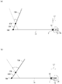
- FIG. 1 is a schematic view of an example in which a turning radius changing device (hereinafter referred to as changing device 10) of a crank arm 1 according to the present invention is applied to a wiper device 100 of an automobile.
- the changing device 10 of the present invention can be applied to various devices such as, for example, other devices for automobiles, vehicles and processing devices other than automobiles, and game machines, in addition to the wiper device 100 for automobiles.
- a wiper device 100 is installed in, for example, a body A of an automobile, and the power of a motor (driving means) 2 fixed to any part of the body A is connected to a crank arm 1.
- the wiper arm 13 is converted to reciprocating swing, and the windshield 19 is wiped by the wiping body 14 connected to the tip of the wiper arm 13.
- the crank arm 1 is rotatably connected to the link arm 11 by a connecting shaft 16 and supported by a holder (support member) 3.
- the crank arm 1 rotates together with the holder 3 to which a rotational force is applied to the drive shaft 21 of the motor 2,
- the arm 11 is reciprocated linearly along its length.
- the link plate 12 is integrally connected or joined to the base of the wiper arm 13.
- the link plate 12 is rotatably supported by a pivot shaft 17 fixed to the body A. When a linear motion is transmitted from the link arm 11, the link plate 12 swings around the pivot shaft 17 and swings the wiper arm 13.
- the wiper arm 13A disposed on the passenger seat side and the wiper arm 13B disposed on the driver seat side are provided side by side.
- a connecting link arm 15 is provided between the link plates 12A and 12B connected to the wiper arms 13A and 13B.
- the link plate 12A is rotatably supported on the link arm 11 by a pin 18A at one end, and is rotatably supported by the body A by a pivot shaft 17A, integrated with the wiper arm 13A at the other end.
- the link plate 12B is rotatably supported on the connecting link arm 15 at one end by a pin 18B, and is integrated with the wiper arm 13B at the other end to be rotatably supported on the body A by a pivot shaft 17B.
- the connecting link arm 15 is rotatably supported by the pin 18A together with the link plate 12B, linearly moves together with the link arm 11, and rotates the link plate 12B in conjunction with the swing of the link plate 12A.
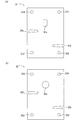
- the changing device 10 has a function of displacing the rotation center position of the crank arm 1 in the crank arm length direction, and changes the rotation radius of the crank arm 1 by the displacement, thereby linking the link arm. 11 reciprocating linear motion strokes are changed.
- the displacement function of the changing device 10 is fixed to the drive shaft 21 of the motor 2 and is given a rotational force, and a holder 3 as a support member that supports the crank arm 1 so as to be reciprocally movable in its length direction; And changing means 4 for changing the fixed position of the crank arm 1 with respect to the holder 3.
- the changing means 4 is activated by operation of a switching operation device 20 electrically connected to a power supply source.
- the “width direction” of the holder 3 means a direction (left-right direction in the drawing) orthogonal to the length direction of the crank arm 1 in plan view.
- crank arm 1 other than the relative movement in the length direction with respect to the holder 3 is constrained in a state where the crank arm 1 is inserted into the holder 3, and rotates integrally with the holder 3 by the rotation of the drive shaft 21.
- the crank arm 1 is formed with an insertion hole 1a that is inserted through the drive shaft 21 so as to be long in the length direction of the crank arm 1, for example.
- the crank arm 1 rotates around the drive shaft 21 and moves in the length direction of the crank arm 1 with respect to the drive shaft 21.
- the insertion hole 1 a is formed between a substantially middle point in the length direction of the crank arm 1 and the connecting shaft 16.
- arc-shaped convex portions 1 c are formed on both edges of the crank arm 1. Therefore, friction between the holder 3 and the crank arm 1 is reduced, and the movement of the crank arm 1 in the length direction is performed smoothly.
- the crank arm 1 includes a connecting portion 1A connected to the link arm 11 via a connecting shaft 16 and an insertion portion 1B inserted into the holder 3.
- the connecting portion 1A has, for example, an L shape, and includes a side wall 1d erected from one end of the insertion portion 1B and a top wall 1e formed from the side wall 1d toward the center of the crank arm 1.
- An insertion hole 1f into which the connecting shaft 16 is inserted is formed in the top wall 1e.
- the connecting shaft 16 is a ball joint.
- the insertion portion 1B and the top wall 1e of the connecting portion 1A are separated from each other in the axial direction of the drive shaft 21, and when the drive shaft 21 is located at the end portion closer to the connecting portion 1A of the insertion hole 1a, the top wall 1e
- the holder 3 overlaps in plan view.
- the rotation radius of the crank arm 1 can be reduced, and the installation space for the changing device 10 can be reduced.
- the movement of the crank arm 1 in the length direction relatively moves the drive shaft 21 between both end portions of the insertion hole 1a.
- the rotation center position of the crank arm 1 is displaced in the length direction of the crank arm, and the rotation radius of the crank arm 1 is the position of the drive shaft 21 in the insertion hole 1a formed in the crank arm 1, that is, the connecting shaft. 16 and the drive shaft 21 are changed according to the positional relationship.
- the distance (rotational radius) L1 from the driving shaft 21 to the connecting shaft 16 is minimized.
- the turning radius of is minimal.
- the swing range of the wiper arms 13A and 13B is twice the swing range before the change. Therefore, the maximum range in which the distance between the drive shaft 21 and the connecting shaft 16 (the rotation radius of the crank arm 1) is changed is determined according to the length and the formation position of the insertion hole 1a. For this reason, the length and formation position of the insertion hole 1a are appropriately set according to the target wiping ranges of the wiping bodies 14A and 14B.
- the formation position of the insertion hole 1a with respect to the width direction of the crank arm 1 is not limited, but when it is formed at the center in the width direction as shown in the drawing, the drive shaft 21 should not be eccentric to the crank arm 1 and the holder 3. Therefore, the region through which these rotations pass is minimum in the crank arm 1 and the holder 3 having the same size, which is preferable.
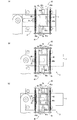
- a plurality of engagement notches 1b are formed on the edge (outer side surface) of the crank arm 1, and engagement members (moving bodies) 41 and 42 constituting the changing means 4 described later are engaged with the engagement notches 1b.
- the mating pieces 41a and 42a are engaged.
- the engagement notch 1b is formed at the edge.
- the engagement pieces 41a and 42a are separately provided on both sides of the crank arm 1, the engagement notches 1b are also formed on both edges. That is, the shape / position of the engagement notch 1b corresponds to the shape / position of the engagement pieces 41a, 42a.
- the holder 3 is nipped and fixed by, for example, two bolts 22 attached to the drive shaft 21, and is driven while being inserted through the drive shaft 21.
- Two flat substrates 31 and 32 arranged in parallel in the axial direction of the shaft 21 (vertical direction in the figure), and a rotating body 34 in contact with the edge of the crank arm 1 are provided.
- the board 31 and the board 32 have insertion holes 31 a and 32 a that are inserted into the drive shaft 21, and engagement pieces 41 a and 42 a of the engagement members 41 and 42, respectively.
- Insertion notches 31b and 32b to be inserted and rotation shaft member holes 31d and 32d to be inserted into the rotation shaft member 34A of the rotating body 34 are formed at predetermined positions.
- the opposite ends of the predetermined section in the axial direction from the tip of the drive shaft 21 are cut in the axial direction.
- the insertion hole 31 a of the substrate 31 is formed in a shape that can be fitted to the drive shaft 21.
- the rotating body 34 includes a rotating shaft member 34A that is fixed between the substrates 31 and 32, and a rotating member 34B that is rotatably supported by the rotating shaft member 34A. At least one rotating body 34 is disposed on each edge of the crank arm 1.
- the rotating shaft member 34A includes a pair of male screws and female screws, and a washer 34C is disposed as appropriate.
- an arc-shaped recess 34a is formed inward on the outer peripheral surface of the rotating member 34B over the entire circumference.
- the crank arm 1 moves in the width direction and moves in the axial direction of the rotating shaft member 34A. The movement of is restricted.
- the rotating member 34B is made of a bearing such as a ball bearing, for example. Therefore, the movement of the crank arm 1 in the length direction is smoothly performed. Further, for example, a washer is interposed between the inner ring (not shown) constituting the bearing and the substrates 31 and 32, and the male screw and the female screw are screwed together, whereby the rotating member 34B can be rotated. While maintaining, the substrates 31 and 32 can be firmly fixed to improve the structural stability of the holder 3.
- the rotation member 34B is made of a bearing, the rotation of the rotation member 34B in the axial direction of the rotation shaft member 34A is eliminated. Therefore, the crank arm 1 restrained by the rotation member 34B in the axial direction of the rotation shaft member 34A is eliminated. Restraint is also ensured.
- the convex part 1c of the crank arm 1 and the concave part 34a of the rotating member 34B are fitted, it is desirable because the restraint by the rotating body 34 of the crank arm 1 is further ensured.
- the change means 4 regulates the reciprocation of the crank arm 1 with respect to the drive shaft 21 by switching the engagement pieces 41a, 42a and the engagement notches 1b to be engaged, thereby fixing the crank arm 1 with respect to the holder 3. That is, the rotation radius of the crank arm 1 is changed.
- the changing means 4 is installed on the upper surface of the substrate 31 and moves the engaging members 41 and 42 for locking the crank arm 1 in its length direction, and the engaging members 41 and 42 in a direction away from the crank arm 1.
- a bistable self-holding solenoid hereinafter referred to as solenoid) (moving means) 43, a fixing portion 44 for fixing the solenoid 43 to the holder 3, and engaging members 41, 42 in a direction to engage the crank arm 1.
- a biasing member 45 for biasing.
- the solenoid 43 is supported and fixed by a fixing portion 44 fixed to the substrate 31.
- the fixing portion 44 includes, for example, a plurality of (two in the drawing) fixing members 44A and 44B having an L-shape, and the fixing members 44A and 44B have a length direction aligned with the width direction of the crank arm 1. Are arranged side by side in the longitudinal direction of the crank arm 1.
- Each of the fixing members 44A and 44B includes a bottom portion 44a and a side portion 44b provided continuously from the bottom portion 44a.
- the bottom portion 44a is disposed on the outer side in the longitudinal direction of the crank arm 1, and the side portion 44b is disposed on the inner side. Has been.
- Both the fixing members 44A and 44B are fixed to the substrate 31 at the bottom 44a and supported with the solenoid 43 sandwiched between the side portions 44b.
- the bottom portions 44a of the fixing members 44A and 44B are sandwiched between the female screw of the fixed shaft member 34A and the substrate 31 and fixed by screwing.
- a predetermined male screw 44C is fitted into the side portion 44b from the outside and protrudes inward, and is screwed into a housing 43c that accommodates the solenoid 43 to support the housing 43c.
- a notch 44c is formed in the bottom 44a of the fixing member 44A, and the drive shaft 21 is disposed in the notch 44c. This is because the size of the holder 3 is reduced by consolidating the drive shaft 21 and the changing means 4.
- a restraining member 46 having an L shape is disposed between the fixing members 44A and 44B in a state where the length direction thereof coincides with the length direction of the fixing members 44A and 44B.
- the restraining member 46 is connected to the bottom plate 46a located at a predetermined distance from the substrate 31 between the solenoid 43 and the substrate 31, and the side plate 44b of either one of the fixing members 44A and 44B and the housing. 43c and a side plate 46b positioned between 43c and supported by male screws 44C. It is desirable that the distance between the bottom plate 46a of the restraining member 46 and the substrate 31 matches the thickness of the insertion pieces 41b and 42b of the engaging members 41 and 42 described later. This is to restrain the movement of the drive shaft 21 of the engaging members 41 and 42 in the axial direction.
- the changing means 4 has two engaging members 41 and 42, and each has the same shape and structure.
- One engagement member 41 is disposed on the other engagement member 42 in a state of being rotated 180 degrees in plan view.
- the engaging members 41 and 42 are inserted between the restraining member 46 and the substrate 31, for example, insertion pieces 41b and 42b having a rectangular shape in plan view, and one end.
- insertion pieces 41b and 42b having a rectangular shape in plan view, and one end.
- transmission pieces 41 c and 42 c that receive the load of the solenoid 43.
- the insertion pieces 41b and 42b are inserted between the restraining member 46 and the substrate 31 so that the long side direction thereof coincides with the width direction of the crank arm 1,
- the crank arm 1 is juxtaposed in the length direction. Since the distance between the side portions 44b and 44b of the fixing members 44A and 44B is equal to the sum of the short side lengths of the insertion pieces 41b and 42b arranged side by side, the insertion pieces 41b and 42b are mutually connected on the inner surface.
- the insertion pieces 41b and 42b are constrained in the length direction of the crank arm 1 because they are in contact with and contact the side portions 44b of the fixing members 44A and 44B facing each other on the outer surface.
- the insertion pieces 41 b and 42 b are also restrained in the axial direction of the drive shaft 21. It is movable only in the long side direction (width direction of the crank arm 1).
- arc-shaped convex portions 41d and 42d are formed outwardly at both edges of the insertion pieces 41b and 42b.
- the engagement pieces 41 a and 42 a are located on the outer side in the length direction of the crank arm 1, and the engagement piece of one engagement member 41 A predetermined distance is secured between 41 a and the engagement piece 42 a of the other engagement member 42. Further, the engagement pieces 41 a and 42 a protrude toward the base end side of the drive shaft 21 and intersect the axial direction of the crank arm 1.
- the engagement piece 41a and the engagement piece 42a are disposed at a predetermined distance in the length direction of the crank arm 1, whereas the engagement notch 1b is the length of the crank arm 1. They are formed at substantially the same position in the vertical direction. That is, the positional relationship between the engagement pieces 41a and 41b is different from the positional relationship between the engagement notches 1b and 1b. Accordingly, the two engagement pieces 41a and 42a are not inserted into the engagement notch 1b at the same time. Further, the fixed position of the crank arm 1 with respect to the holder 3, that is, the distance between the drive shaft 21 and the connecting shaft 16 is determined by the positional relationship between the engagement notch 1b and the engagement pieces 41a and 42a in the length direction of the crank arm 1. Is done.
- the engagement pieces 41 a and 42 a are formed longer than the axial length of the drive shaft 21 of the holder 3 and are inserted into the insertion cutouts 31 b and 32 b of both the boards 31 and 32 and the engagement cutout 1 b of the crank arm 1. .
- the engagement pieces 41 a and 42 a may be shorter than the axial length of the drive shaft 21 of the holder 3 as long as the engagement pieces 41 a and 42 a are inserted and engaged with the engagement notches 1 b of the crank arm 1.
- the engagement pieces 41a and 42a are fixed when the engagement pieces 41a are inserted into the insertion notches 31b and 32b of the two substrates 31 and 32 having a predetermined distance. This is preferable because it can be ensured.
- Arc-shaped convex portions 41e and 42e are formed outward on the side surfaces of the engagement pieces 41a and 42a that face the crank arm 1, and the friction coefficient between the engagement pieces 41a and 42a and the crank arm 1 is reduced.
- the transmission pieces 41c and 42c protrude in the opposite direction (upper side in the drawing) to the engagement pieces 41a and 42a and face the solenoid 43.
- the transmission pieces 41c and 42c may be constituted by a single piece, and as shown in FIGS. 6A to 6D, the transmission pieces 41c and 42c are connected and transmitted to the transmission pieces 41c and 42c by, for example, a set of bolts and nuts. It is also possible to fix the pieces 41f and 42f and form them integrally.
- the transmission pieces 41c and 42c protrude outward from the positions of the side walls 44b of both the fixing members 44A and 44B in the length direction of the crank arm 1, and the protruding portion (hereinafter referred to as the protruding portion) has a biasing member 45.
- the urging member 45 is composed of, for example, an elastic body such as a spring, and is laid between opposing projecting portions.
- the urging direction of the urging member 45 coincides with the long side direction of the insertion pieces 41b and 42b. Therefore, the long side direction movement of the insertion pieces 41a and 42a of the engaging members 41 and 42 is performed smoothly.
- the solenoid 43 is connected to a movable iron core (not shown) and has output shafts 43a and 43b arranged coaxially, and the output shaft 43a, 43b moves integrally in the axial direction.
- the axial direction of the output shafts 43a and 43b is orthogonal to the length direction of the crank arm 1 in plan view, and is opposed to one of the transmission pieces 41c and 42c of the engaging members 41 and 42, respectively. .
- the output shafts 43a and 43b protrude from both end faces of a housing 43c that houses a movable iron core and a fixed iron core (not shown).
- the output shaft is oriented in a direction corresponding to the flowing current. 43a and 43b move, and either one of the output shafts 43a and 43b protrudes from the end face of the housing 43c.
- a lead wire (not shown) connected to the solenoid 43 is inserted into a through hole (not shown) formed in the drive shaft 21, and a base end portion (for example, the drive shaft 21) This is performed by being connected to a rotating contact conductor (brush) (not shown) such as a copper plate / copper foil installed in the worm gear).
- the connecting conductor is electrically connected to a predetermined power supply source via a switching operation unit 20 such as a switching switch for switching the direction of the current flowing through the solenoid 43.
- the output shaft 43a protrudes from the end face of the housing 43c so as to abut against the transmission piece 41c of the engagement member 41, and the engagement piece 41a of the engagement member 41 is released.
- the biasing member 45 is in a biased state, and biases the engaging member 41 inward in the width direction of the crank arm 1.
- the transmission piece 42c of the engagement member 42 is located away from the tip of the output shaft 43b, and the engagement piece 41a and the engagement notch 1b face each other. It is not opposed to 1 b, and is biased by the biasing member 45 and locked to the edge of the crank arm 1.
- the engaging member 41 is locked to the output shaft 43a, and the engaging member 42 is locked to the crank arm 1 outward in the width direction of the crank arm 1, and at the same time, the biasing member 45 is applied inward in the width direction of the crank arm 1. Therefore, it is restrained by the crank arm 1 restrained by the holder 3 or the moving means 43 fixed to the holder 3, so that the engagement members 41, 42 are prevented from being detached from the changing means 4.
- the engagement notch 1 b formed on the engagement piece 42 a side of the engagement member 42 is an engagement piece of the engagement member 42 in the length direction of the crank arm 1.
- the engaging member 41 is locked to the output shaft 43a, so that only the engaging member 42 of the crank arm 1 is moved by the biasing member 45 as shown in FIG. It moves inward in the width direction, and the engagement piece 42a is inserted into the engagement notch 1b and engaged.
- the crank arm 1 is engaged with the engagement piece 41a, and the movement of the crank arm 1 in the length direction is restricted.
- the urging member 45 is in the urging state in order to prevent the engagement members 41 and 42 from being detached from the changing means 4.
- the crank arm 1 moves in the length direction, and the engagement piece 41a and the engagement notch formed at the edge of the crank arm 1 facing the engagement piece 41a. 1b and the crank arm 1 at the same position in the length direction, the engagement piece 41a is inserted into the engagement notch 1b by the urging force of the urging member 45 as shown in FIG. Engage with the arm 1.
- crank arm 1 and the link arm 11 are rotatably connected via the connecting shaft 16, the crank arm 1 rotates about the connecting shaft 16 with respect to the link arm 11. That is, the angle ⁇ between the crank arm 1 and the link arm 11 changes from 0 ° to 360 ° with the connecting shaft 16 as the apex.
- crank arm 1 and the link arm 11 When the angle ⁇ between the crank arm 1 and the link arm 11 is 0 ° (360 °), the crank arm 1 and the link arm 11 are coaxial, and the drive shaft 21 is between the pin 18A and the connecting shaft 16. Is located, and the turning radius of the crank arm 1 is minimum.
- crank arm 1 When the driving means 2 is driven and the crank arm 1 starts to rotate clockwise, the crank arm 1 is connected to the connecting shaft 16 by the frictional force between the wiping bodies 14A and 14B and the windshield 19 as shown in FIG. As a result, the crank arm 1 moves in the length direction so that the drive shaft 21 moves to the end of the insertion hole 1a opposite to the connecting shaft 16. Thereby, the rotation center position of the crank arm 1 is displaced in the crank arm length direction (specifically, the direction in which the drive shaft 21 is relatively separated from the connecting shaft 16), and the rotation radius of the crank arm 1 is increased. .
- crank arm 1 when the angle ⁇ between the crank arm 1 and the link arm 11 is 270 °, the turning radius of the crank arm 1 is maximum. Until the angle ⁇ between the crank arm 1 and the link arm 11 reaches 360 ° (0 °), the crank arm 1 is linked to the link arm via the connecting shaft 16 by the frictional force between the wiping bodies 14A and 14B and the windshield 19. 11, the crank arm 1 moves in the length direction so that the drive shaft 21 moves to the end portion of the insertion hole 1 a near the connecting shaft 16 as shown in FIG. The turning radius of 1 becomes smaller. Thereafter, the crank arm 1 repeats the same operation.
- the crank arm 1 can be used by using the rotational movement of the crank arm 1 for reciprocating linear movement of the link arm 1. It is possible to change the rotation radius of the.
- the resistance force when transmitting through the link arm 11 is large, which is optimal for the automobile wiper device 100 of this application example. It is.
- the crank unit 1 makes one rotation by the driving unit 2 and performs two reciprocations in the length direction
- the above-described changing unit 4 when the above-described changing unit 4 is operated, the positions of the engagement pieces 41a and 42a and the engagement disengagement are determined. It can be changed to the turning radius of the crank arm 1 determined by the position of the notch 1b. Since the engagement pieces 41a and 42a to be engaged with the crank arm 1 can be selected by the switching operation device 20, the turning radius of the crank arm 1 can be automatically changed from the outside.
- the existing crank mechanism for transmitting the power of the driving means 2 to the link arm 11 and the changing device 10 are exchanged, the existing link mechanism for transmitting the power by the link arm 11 can be used, which is economical.
- the wiping body 14 does not cause an overload on the drive unit 2. It is possible to increase the number of wiping operations per unit time. Specifically, the longer the distance between the connecting shaft 16 that is the transmission position of the rotational force by the crank arm 1 and the driving shaft 21, the lower the rotational speed of the driving shaft 21 by the driving means 2 and the driving of the connecting shaft 16 and the driving shaft 21. Increasing the number of reciprocating motions of the link arm 11 while suppressing a significant increase in the load of the driving means 2 by increasing the rotational speed of the driving shaft 21 by the driving means 2 as the distance from the shaft 21 becomes shorter. Can do.
- the drive shaft 21 is driven by the drive means 2.
- the number of wiping operations of the wiping body 14 per unit time can be doubled while keeping the load of the driving means 2 as it is.
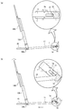
- FIG. 13 is a view showing an example in which the turning radius changing device 10 for the crank arm 1 according to the present invention is applied to the nozzle device 200.
- the same names and symbols are used for portions common to the first embodiment, and description thereof is omitted.
- the nozzle device 200 of this application example shown in FIG. 13 is an artificial rain device that sprays water on the windshield of an automobile.
- the changing device 10 a nozzle 61 that is connected to a hose and injects water, and moves the nozzle 61.
- the rails 63 are arranged such that their length directions coincide with the horizontal direction, and are connected to each other.
- the rail 63 is composed of a pair of angles (equal side angle or unequal side angle) of the same standard, and the side plate of each angle is disposed on the outside and the bottom plate is disposed on the inside.
- a guide portion 64 that guides the movable frame body 62 is formed in the length direction of the rail 63.
- the guide portion 64 is a round bar, but is set appropriately.
- the movable frame body 62 includes a pulley 621 that is movable along the guide portion 64.
- the movable frame body 62 is mounted so that the pulley 621 is fitted to a pair of guide portions 64 provided in the rail 63 and linearly movable in the length direction of the rail 63 so that the plane on which the nozzle 61 is installed intersects the horizontal plane. Has been.
- the holder 3 is supported by the drive shaft 21 of the motor 2 disposed at one end of the rail 63 so that the rotation surface of the crank arm 1 intersects the horizontal plane.
- the link arm 11 is rotatably supported on the crank arm 1 by a connecting shaft 16 at one end, and is rotatably connected to the movable frame body 62 via a pin 18A at the other end.
- movable frame bodies 62A and 62B and nozzles 61A and 61B arranged on the driver's seat side and movable frame body 62C and nozzle 61C arranged on the passenger seat side are arranged in parallel.
- a connecting link arm 65 is installed between the movable frame bodies 62A and 62B and between the movable frame bodies 62B and 62C, and the movable frame bodies 62A to 62C are connected.
- the movable frame 62C and the crank arm 1 are connected via the link arm 11, and the movable frame 62C performs a reciprocating linear motion as the crank arm 1 rotates. Therefore, the movable frame bodies 62A and 62B perform the reciprocating linear motion in conjunction with the reciprocating linear motion of the movable frame body 62C.
- crank arm 1 reciprocates once in the length direction during one rotation. This is because the rotation surface of the crank arm 1 intersects the horizontal plane, and the movable frame 62 moves using the pulley 621 and the guide portion 64, so there is almost no resistance when the movable frame 62 moves. This is because there is almost no axial force acting on the crank arm 1.
- the crank arm 11 swings around the pin 18A. Therefore, the crank arm 1 moves downward also by the weight of the link arm 11. Specifically, when the connecting shaft 16 is positioned below the drive shaft 21, as shown by an arrow in FIG. 9B, the link shaft 11 moves downward due to the weight of the link arm 11, and the drive shaft 21 is inserted into the insertion hole 1a. Even when the connecting shaft 16 is located above the drive shaft 21, it is moved downward by its own weight of the crank arm 1 as shown by an arrow in FIG. The drive shaft 21 is located at the end near the connecting shaft 16.
- the drive shaft 21 comes into contact with the end of the insertion hole 1 a far from the connecting shaft 16, and the rotation radius of the crank arm 1 is maximized.
- the drive shaft 21 comes into contact with the end of the insertion hole 1 a near the connecting shaft 16, and the rotation radius of the crank arm 1 is minimized. That is, each time the crank arm 1 makes one rotation with the holder 3 around the drive shaft 21, the crank arm 1 reciprocates once between a position where the rotation radius is maximum and a position where the rotation radius is minimum.
- the crank arm 1 By restricting the reciprocating movement and fixing the rotation radius of the crank arm 1 around the drive shaft 21, the crank arm 1 can be used by using the rotational movement of the crank arm 1 for reciprocating linear movement of the link arm 1. It is possible to change the rotation radius of the. When the rotation radius of the crank arm 1 is changed using this phenomenon, it is preferable that the resistance force when power is transmitted via the link arm 11 is small.
- the rotation radius of the crank arm 1 can be changed to be determined by the positions of the engagement pieces 41a and 42a and the position of the engagement notch 1b. Since the engagement pieces 41a and 42a to be engaged with the crank arm 1 can be selected by the switching operation device 20, the turning radius of the crank arm 1 can be automatically changed from the outside.
- the crank arm 1 is rotated vertically or obliquely with respect to the horizontal direction. Therefore, as in the second embodiment, the connection is made under the influence of gravity acting on the crank arm 1 and the link arm 11. A force acts to move the crank arm 1 with the shaft 16 positioned above or below the drive shaft 21 downward. However, when the resistance force acting via the link arm 11 is larger than that in the second embodiment, the downward movement of the crank arm 1 may be hindered by this resistance force.
- the effect of resistance increases as the number of revolutions of the crank arm 1 increases. This is because the crank arm 1 is rotated against the resistance transmitted through the link arm 11, and the crank arm 1 can move in the vertical direction without being affected by the resistance. Since the rotational position of 1 is limited, if the rotational speed is too high, the crank arm 1 will rotate to the rotational position that is greatly affected by the resistance force again before the crank arm 1 is sufficiently moved downward. It is believed that there is.
- a biasing member such as a spring may be used to constantly bias the crank arm 1 downward so that the crank arm 1 can be reliably moved downward.
- the downward urging of the crank arm 1 is preferably performed via the link arm 11. This is because when the urging member is attached to the crank arm 1 that rotates around the drive shaft 21, the arrangement and mounting structure of the urging member are limited so as to avoid contact with the holder 3 and the drive shaft 21. On the other hand, when the urging member is attached to the link arm 1, there is no such limitation.
- FIG. 14A shows a state of 90 ° while the angle between the crank arm 1 and the link arm 11 is changed from 0 ° to 90 °.
- FIG. 15A shows a state of 270 ° while the angle between the crank arm 1 and the link arm is changed from 180 ° to 270 °.
- the changing device 10 according to the present embodiment has a configuration in which the changing device 10 according to the first embodiment includes an urging member 5 installed on the link arm 11 and the body A.
- the urging member 5 is formed of an elastic body such as a spring, for example, and has one end on the crank arm 1 side from the center in the length direction of the link arm 11, and the other end at a position substantially lower than the link arm 11.
- the link arms 11 are always urged downwards, respectively.
- the crank arm 1 whose angle rotates clockwise from 0 ° to 90 ° includes the gravity acting on the crank arm 1 and the link arm 11, the tensile force of the link arm 11, and the biasing member. 5, the end of the insertion hole 1a opposite to the connecting shaft 16 is moved closer to the drive shaft 21, and the rotation radius of the crank arm 1 is increased. As shown in FIG. 14B, when the end of the insertion hole 1a opposite to the connecting shaft 16 comes into contact with the drive shaft 21, the turning radius of the crank arm 1 is maximized.
- crank arm 1 that rotates clockwise from 180 ° to 270 ° has the gravity acting on the crank arm 1 and the link arm 11 due to the tensile force of the link arm 11.
- the end of the insertion hole 1a opposite to the connecting shaft 16 moves against the driving shaft 21 against the urging force of the urging member 5, and the turning radius of the crank arm 1 increases.
- the connecting shaft 16 is positioned below the drive shaft 21 while the crank arm 1 makes one rotation with the holder 3 around the drive shaft 21.
- the urging force exerted on the crank arm 1 by the urging member 5 can be set as appropriate. For example, when the crank arm 1 rotates clockwise from 180 ° to 270 °, it is opposite to the connecting shaft 16 of the insertion hole 1a. The urging force may be applied so that the side end moves as it is without approaching the drive shaft 21.
- the mounting position of the urging member 5 can also be set as appropriate so that a sufficient urging force can be applied to the crank arm 1 via the link arm 11.
- FIG. 18 is an explanatory diagram of another embodiment of the crank arm turning radius changing device according to the present invention.
- the same names and symbols are used for portions common to the first embodiment, and description thereof is omitted.
- the strength of the rotating member 34B is improved by adopting a metal bearing such as a ball bearing as an example of the rotating member 34B described in the first embodiment.
- a metal bearing is configured such that the inner peripheral surface of the inner ring is fixed to the outer peripheral surface of the rotating shaft member 34 ⁇ / b> A, and the outer peripheral surface of the outer ring is in contact with the edge of the crank arm 1.
- the first and second substrates 31 and 32 are configured so as to restrain the movement of the crank arm 1 in the axial direction of the rotating shaft member 34A with the adoption of the bearing 34B-1.
- a plurality of rollers 7 shown in FIG. 19 are provided on the inner surface (the surface facing the crank arm 1), and a part of the outer peripheral surface of these rollers 7 is in contact with the crank arm 1 from the front and back sides of the crank arm 1.
- the plurality of rollers 7 provided on the first substrate 31 are arranged side by side along the crank arm length direction (arrow Y direction) as shown in FIGS. This also applies to the plurality of rollers 7 provided on the second substrate 32.
- the roller 7 (7A) located on the distal end side of the crank arm 1 is provided so as to be in contact with the substantially central portion in the width direction of the crank arm 1.
- two rollers 7 (7B, 7B) positioned on the rear end side of the crank arm 1 are arranged side by side in the width direction of the crank arm 11 so as to contact both edges of the insertion hole 1a of the crank arm 1. It is provided as follows. This is because the rollers 7 (7B, 7B) can reliably contact the crank arm 1 while avoiding the insertion hole 1a of the crank arm 1.
- FIG. 19 is an explanatory diagram of the roller 7 employed in the changing device 10 of FIG.
- the roller 7 in the figure has a cylindrical shape and is rotatably held by upper and lower cages 71 and 72.
- the upper cage 71 includes a recess 71A for accommodating the upper half of the roller 7 in the radial direction, an opening 71B for exposing the outer peripheral surface of the roller 7 to the outside from the bottom of the recess 71A, A bearing groove 71C that rotatably supports a shaft (hereinafter referred to as a roller shaft 70) is configured.
- the lower retainer 72 includes a recess 72 ⁇ / b> A for accommodating the lower half of the roller 7 in the radial direction.
- the upper and lower cages 71 and 72 are The upper and lower cages 71 and 12 are integrated by being fixed by a fixing means (not shown). Thereby, the roller 7 is held rotatably about the roller shaft 70, and a part of the outer peripheral surface of the roller is exposed to the outside from the opening 71 ⁇ / b> B of the upper cage 71.
- FIG. 20 is a plan view of the first and second substrates 31 and 32 used when the roller 7 of FIG. 19 is employed.
- a plurality of windows 8 for inserting the rollers 7 and the retainers 71 on the upper side thereof are opened on the substrates 31 and 32 in FIG. 20, and these windows 8 are both front and back surfaces of the substrates 31 and 32. It is formed so as to penetrate.
- FIG. 21 is an explanatory diagram showing a state in which the roller 7 is attached to installation plates 8A and 8B for installing the roller 7 of FIG. 19 on the inner surfaces of the substrates 31 and 32 of FIG.
- roller mounting recesses 80 corresponding to the window 8 of FIG. 20, as shown in FIGS. Then, by inserting the lower cage 72 of the roller 7 into the respective roller mounting recesses 80 by press-fitting, the roller 7 is integrally mounted on the installation plates 8A and 8B.
- a method of attaching the roller 7 to the installation plates 8A and 8B a method different from the above-described press fitting may be adopted.
- the installation plate 8A to which the roller 7 is attached is screwed and fixed to the substrate 31 in a state where the roller 7 and the upper retainer 71 are inserted into the window 8 of the substrate 31. Thereby, a part of the outer peripheral surface of the roller 7 (a portion exposed from the opening of the upper retainer 71 ⁇ / b> A) is exposed from the window 8 and can come into contact with the crank arm 1.
- the installation plate 8B to which the roller 7 is attached is also fixed to the substrate 32 in the same manner as the installation plate 8A described above.
- the rollers 7 of the first substrate 31 and the rollers 8 of the second substrate 32 are shown in FIGS. ) And FIG. 18B, and a part of the outer peripheral surface of the roller 7 comes into contact with the crank arm 1 from both the front and back sides of the crank arm 1. This contact restrains the movement of the crank arm 1 in the axial direction of the rotating shaft member 34A.
- roller 7 ⁇ Comparison of roller 7 and bearing BR>
- a commercially available bearing BR as shown in FIG.
- the roller 7 is compared with a bearing (commercially available product) having a load resistance specification comparable to that of the roller 7, the roller 7 has a smaller diameter and is not bulky in the thickness direction of the substrates 31 and 32, and the number of components is small and inexpensive.
- the engaging members 41 and 42 in FIG. 22 are inserted into the long holes 31f and 32f (see FIGS. 18A and 20A and 20B) of the substrates 31 and 32 to engage with the crank arm 1.
- the coupling pieces 41a, 42a, transmission pieces 41c, 42c formed integrally with the engagement pieces 41a, 42a and receiving the load of the solenoid 43, and rotating bodies 41g, 42g attached to the engagement pieces 41a, 42a. .
- the engaging members 41 and 42 in FIG. 22 are the same as the engagement members 41 and 42 in FIG. 6, and the long holes 31f and 32f of the substrates 41 and 42 (the insertion notches 31b in the engagement members 41 and 42 in FIG. 32b), and the engagement pieces 41a and 42a engage with the engagement notches 1b and 1b of the crank arm 1, thereby locking the crank arm 1 in its length direction.
- the engaging members 41 and 42 in FIG. 22 have a structure in which the convex portions 41h and 42h provided at the ends of the engaging pieces 41a and 42a engage with the engaging notches 1b and 1b of the crank arm 1, respectively.
- the shape without the convex portions 41h and 42h may be used.
- Rotating bodies 41g and 42g of the engaging members 41 and 42 are disposed between the two substrates 31 and 32. As described above, when the engaging members 41 and 42 slide along the long holes 31f and 32f, the rotating bodies 41g and 42g rotate while contacting the inner surfaces of both the boards 31 and 32, thereby It plays the role which makes the sliding operation
- rotating bodies 41g and 42g of the engaging members 41 and 42 for example, metal ball bearings or other rolling bearings can be employed, and the rollers 7 shown in FIG. 19 can also be employed. .
- each of the engaging members 41, 42 has kick springs 45 ⁇ / b> A, 45 ⁇ / b> B corresponding to the vicinity thereof.
- a configuration is adopted in which the two engaging members 41 and 42 are individually biased by the kick springs 45A and 45B.
- the urging directions of the engaging members 41 and 42 by the kick springs 45A and 45B are the same as those of the urging member 45 including one spring shown in FIG.
- FIG. 23 is a cross-sectional view showing an example of a connection structure between the drive shaft 21 and the substrates 31 and 32 of the holder 3 in the changing device 10 of FIG.
- two steps 21A and 21B are formed at the end of the drive shaft 21 in the connection structure of FIG.
- the upper and lower steps 21A and 21B have a shape in which both sides of the outer periphery opposite to the drive shaft 21 are cut in the axial direction, similarly to the drive shaft 21 described in the first embodiment (see FIG. 4).
- the portion is referred to as a first cut shape portion 21C), and the shape from the upper step to the tip of the drive shaft 21 is similarly cut (hereinafter, this shape portion is referred to as a second cut shape portion 21D) and the male screw 21E. It is formed continuously. Further, as shown in FIGS.
- the insertion hole 31a of the first substrate 31 is formed in accordance with the radial cross-sectional shape of the first cut shape portion 21C, and
- the insertion hole 32a is formed according to the radial cross-sectional shape of the second cut shape portion 21D.
- the operation of connecting the drive shaft 21 and the holder 3 is an operation of fitting the second cut-shaped portion 21D of the drive shaft 21 into the insertion hole 32a (see FIG. 20B) of the second substrate 32.
- a nut 22G is attached and tightened to the male screw 21E of the drive shaft 21. Accordingly, the first substrate 31 is fixed to the upper stage 21A of the drive shaft 21 by the tightening force of the nut 22G, and the drive shaft 21 and the holder 3 are firmly connected and integrated.
- FIG. 25 is an external view in which covers C1 to C4 are attached to the changing device 10 of FIG.
- the first cover C1 is configured to cover the solenoid 43, kick springs 45A and 45b as the biasing member 45, and the long hole 31f (see FIG. 18) of the substrate 31, and the solenoid 43 and the spring 45A It plays the role of preventing foreign matter such as dust and water from coming into direct contact and the role of preventing foreign matter from entering the device 10 through the long hole 31f.
- the second cover C2 covers the outer clearance formed between the first and second substrates 31 and 32, thereby preventing foreign matter from entering the apparatus 10 from the outer clearance.
- the third cover C3 has a bellows shape that can be expanded and contracted following the reciprocating movement of the crank arm, and covers the outer periphery of the rear end side of the crank arm 1 so that the substrate 31, The foreign matter is prevented from entering the inside of the apparatus 10 through the gap between 32.
- the fourth cover C ⁇ b> 4 covers the tip side of the crank arm 1 that protrudes and protrudes between the substrates 31 and 32.
- a protective cover made of rubber or the like for covering the entire substrates 31 and 32 may be further attached in order to reliably prevent intrusion of dust, water and the like.
- FIG. 26 shows another example of the means for moving the engaging members 41 and 42 away from the crank arm 1 in the changing device 10 shown in FIGS. 18 (a), 24 (a) and 4 (b).
- FIG. 25 is an explanatory diagram of an example in which a motor driving device 430 is employed instead of the solenoid 43 shown in FIGS. 18 (a), 24 (a), and 4 (b).
- the motor driving device 430 includes a small motor M shown in FIG. 27, a reduction gear DG for reducing the rotational speed of the motor M, a pinion P connected to the reduction gear DG, a rack R engaged with the pinion P, And it is comprised from the housing 43C which accommodates these.
- Rotational force of the motor M is transmitted to the pinion P through the reduction gear DG, and the rack R moves linearly by the rotation of the pinion P.
- the direction of the linear movement is a direction in which the engaging members 41 and 42 are separated from the crank arm 1.
- the rack R is provided so as to be orthogonal to the length direction of the crank arm 1 in the same manner as the output shafts 43a and 43b of the solenoid 43 shown in FIGS. 18 (a), 24 (a) and 4 (b).
- the rack ends R1, R2 are configured to face either of the transmission pieces 41c, 42c of the engaging members 41, 42, respectively. This is also the same as the output shafts 43a and 43b of the solenoid 43 shown in FIG.
- the motor M is not overloaded, the life of the motor M is extended, and the gears of the pinion P and the rack R can be prevented from being damaged. Durability can be improved.
- FIG. 26A shows a state where the rack R has linearly moved to the right at the maximum.
- the operation form of the engaging members 41 and 42 when the rack R in FIG. 26A linearly moves to the left side is the solenoid 43 in FIGS. 18A, 24A, and 4B. This is the same as the operation mode of the engaging members 41 and 42 when the output shaft 43a protrudes leftward from the housing 43c.
- the operation mode of the engaging members 41 and 42 when the rack R of FIG. 26A linearly moved to the left as shown in FIG. 26A linearly moves to the right as shown in FIG. 24 (a), FIG. 4 (b), the operation form of the engaging members 41, 42 when the output shaft 43b of the solenoid 43 protrudes to the right side from the housing 43c is the same. Detailed description is omitted.
- the motor driving device 430 can easily adjust the stroke for moving the engaging members 41 and 42, although the number of parts is increased as compared with the solenoid 43 shown in FIG. Further, the force for moving the engaging members 41 and 42 is stronger in the motor driving device 430, and the motor driving device 430 can keep the state after the engaging members 41 and 42 are moved strongly.
- the driving device 430 is preferable.
- the engagement notches 1b and 1b are substantially the same position and the engagement pieces 41a and 42a are different positions in the length direction of the crank arm 1, but FIG.
- the engagement pieces 51a, 51a are formed on one engagement member 51, and are arranged at the same position in the length direction of the crank arm 1 on both edges of the crank arm 1 ′. It is also possible to arrange the engagement notches 1 ′ b at different positions in the length direction of the crank arm 1. Further, as shown in FIGS. 17A and 17B, when the crank arm 1 ′ and the locking member 51 are combined, the engagement notch 1b ′ differs in the length direction of the crank arm 1 ′.
- the joining pieces 41a and 42a can also be in different positions.
- the rotation radius of the crank arm 1 can be changed in two steps of maximum and minimum.
- the present invention is not limited to this.
- the maximum, middle, minimum and three steps are four steps. It is also possible to change to the above.
- the changing means 4 or the engagement notch (engaged portion) 1b is added.
- the changing means 4 may be installed in the holder 3 using, for example, a dry battery as a power supply source of the added changing means 4 and the changing means 4 may be operated by remote control operation.
- the holder 3 is made of a plastic having a smaller frictional resistance than metal.
- the four corners of the holder 3 in contact with the crank arm 1 may be rounded in addition to using the rotating body or the bearing as described above.
- Insertion notch 34 Rotating body 41 ... Engagement member 41a ... Engagement piece (engagement part) 41b ... insertion piece 41c ... transmission piece 41f ... connection transmission piece 42 ... engagement member 42a ... engagement piece (engagement part) 42b ... insertion piece 42c ... transmission piece 42f ... connection transmission piece 43 ... bistable self-holding solenoid (moving means) 43a ... output shaft 43b ... output shaft 44 ... fixed portion 45,5 ... biasing member 46 ... restraining member 100 ... wiper device A ......... body ⁇ ......... angle between crank arm and link arm
Landscapes
- Engineering & Computer Science (AREA)
- General Engineering & Computer Science (AREA)
- Mechanical Engineering (AREA)
- Ocean & Marine Engineering (AREA)
- Transmission Devices (AREA)
Abstract
L'invention concerne un dispositif présentant une structure simplifiée et plus compacte, servant à modifier le rayon de giration d'un bras de manivelle au moyen des forces naturelles s'exerçant sur un mécanisme de manivelle pour modifier la position du centre de giration. Ce dispositif permet également de réduire la puissance motrice nécessaire pour déplacer un arbre de couplage. Ce dispositif de modification de rayon de giration (10) comprend : un support (3) fixé sur un arbre d'entraînement (21) pour recevoir la force rotative transmise par l'arbre ; un bras de manivelle (1) soutenu par le support (3) de sorte à effectuer un mouvement de va-et-vient par rapport au support (3), et qui transmet la force rotative s'exerçant sur le support (3) lorsqu'il pivote avec ce dernier (3) ; et un moyen de modification (4) destiné à modifier la position fixe du bras de manivelle (1) par rapport au support (3). Ce moyen de modification (4) comprend des éléments de contact (41,42) soutenus par le support (3) de sorte à pouvoir se déplacer, un élément de sollicitation (45) destiné à solliciter les moyens de contact (41,42) dans le sens de venue en contact avec le bras de manivelle (1), ainsi qu'un moyen de déplacement (43) servant à déplacer les moyens de contact (41,42) dans le sens de séparation du bras de manivelle (1) par résistance à la force de sollicitation de l'élément de sollicitation (45).
Priority Applications (1)
| Application Number | Priority Date | Filing Date | Title |
|---|---|---|---|
| JP2009554247A JP4536154B2 (ja) | 2008-04-15 | 2009-04-10 | クランクアームの回転半径変更装置と該変更装置を備えた駆動装置 |
Applications Claiming Priority (2)
| Application Number | Priority Date | Filing Date | Title |
|---|---|---|---|
| JP2008105895 | 2008-04-15 | ||
| JP2008-105895 | 2008-04-15 |
Publications (1)
| Publication Number | Publication Date |
|---|---|
| WO2009128400A1 true WO2009128400A1 (fr) | 2009-10-22 |
Family
ID=41199093
Family Applications (1)
| Application Number | Title | Priority Date | Filing Date |
|---|---|---|---|
| PCT/JP2009/057345 Ceased WO2009128400A1 (fr) | 2008-04-15 | 2009-04-10 | Procede et dispositif de modification du rayon de giration d’un bras de manivelle et appareil d’entrainement dote ce dispositif |
Country Status (2)
| Country | Link |
|---|---|
| JP (1) | JP4536154B2 (fr) |
| WO (1) | WO2009128400A1 (fr) |
Cited By (3)
| Publication number | Priority date | Publication date | Assignee | Title |
|---|---|---|---|---|
| CN103101623A (zh) * | 2013-01-21 | 2013-05-15 | 王志成 | 一种环形平板扑翼升力生成装置 |
| CN107339391A (zh) * | 2017-07-10 | 2017-11-10 | 湖南农业大学 | 一种行程可调间歇式往复运动机构 |
| CN111746470A (zh) * | 2020-07-01 | 2020-10-09 | 吉利汽车研究院(宁波)有限公司 | 一种雨刮器总成及车辆 |
Citations (4)
| Publication number | Priority date | Publication date | Assignee | Title |
|---|---|---|---|---|
| JPS5125670Y1 (fr) * | 1970-12-30 | 1976-06-30 | ||
| JPH0373746U (fr) * | 1989-11-20 | 1991-07-24 | ||
| JP2000335375A (ja) * | 1999-05-31 | 2000-12-05 | Shin Caterpillar Mitsubishi Ltd | ワイパ装置のリンク機構 |
| JP2001026257A (ja) * | 1999-07-13 | 2001-01-30 | Jidosha Denki Kogyo Co Ltd | ワイパ制御装置 |
Family Cites Families (3)
| Publication number | Priority date | Publication date | Assignee | Title |
|---|---|---|---|---|
| FR853328A (fr) * | 1939-04-22 | 1940-03-15 | Perfectionnements aux dispositifs de commande pour essuie-glace | |
| DE3738434C2 (de) * | 1987-11-12 | 1996-09-05 | Bosch Gmbh Robert | Wischvorrichtung für Scheiben von Kraftfahrzeugen |
| JP2559620Y2 (ja) * | 1990-04-02 | 1998-01-19 | 自動車電機工業株式会社 | ワイパ装置 |
-
2009
- 2009-04-10 WO PCT/JP2009/057345 patent/WO2009128400A1/fr not_active Ceased
- 2009-04-10 JP JP2009554247A patent/JP4536154B2/ja not_active Expired - Fee Related
Patent Citations (4)
| Publication number | Priority date | Publication date | Assignee | Title |
|---|---|---|---|---|
| JPS5125670Y1 (fr) * | 1970-12-30 | 1976-06-30 | ||
| JPH0373746U (fr) * | 1989-11-20 | 1991-07-24 | ||
| JP2000335375A (ja) * | 1999-05-31 | 2000-12-05 | Shin Caterpillar Mitsubishi Ltd | ワイパ装置のリンク機構 |
| JP2001026257A (ja) * | 1999-07-13 | 2001-01-30 | Jidosha Denki Kogyo Co Ltd | ワイパ制御装置 |
Cited By (4)
| Publication number | Priority date | Publication date | Assignee | Title |
|---|---|---|---|---|
| CN103101623A (zh) * | 2013-01-21 | 2013-05-15 | 王志成 | 一种环形平板扑翼升力生成装置 |
| CN103101623B (zh) * | 2013-01-21 | 2015-03-25 | 佛山市神风航空科技有限公司 | 一种环形平板扑翼升力生成装置 |
| CN107339391A (zh) * | 2017-07-10 | 2017-11-10 | 湖南农业大学 | 一种行程可调间歇式往复运动机构 |
| CN111746470A (zh) * | 2020-07-01 | 2020-10-09 | 吉利汽车研究院(宁波)有限公司 | 一种雨刮器总成及车辆 |
Also Published As
| Publication number | Publication date |
|---|---|
| JP4536154B2 (ja) | 2010-09-01 |
| JPWO2009128400A1 (ja) | 2011-08-04 |
Similar Documents
| Publication | Publication Date | Title |
|---|---|---|
| JP5882946B2 (ja) | スイブルアクチュエータ | |
| US8517156B2 (en) | Clutch actuating apparatus for transmission | |
| JP6604733B2 (ja) | 車両用電動格納式視認装置 | |
| JP4536154B2 (ja) | クランクアームの回転半径変更装置と該変更装置を備えた駆動装置 | |
| US12503061B2 (en) | Rotary adjustment mechanism | |
| CN109050354B (zh) | 一种电动滑轨 | |
| KR20030081806A (ko) | 차량용 스티어링 시스템의 랙바 지지장치 | |
| KR101543524B1 (ko) | 저소음 축소형 틸팅기능을 포함하는 자동차 디스플레이 모니터 | |
| US20060001989A1 (en) | Vehicle outside mirror | |
| CN111720538B (zh) | 驻车机构及车辆 | |
| KR101716453B1 (ko) | 동력전달장치 | |
| JP5324086B2 (ja) | スライダユニットおよびそれを用いたスライダ駆動装置 | |
| JP4973604B2 (ja) | パーキング装置構造 | |
| JP2008167585A (ja) | 減速機構付き電動モータ | |
| JP5617474B2 (ja) | 車両用レバースイッチ | |
| JP2010274702A (ja) | パーキング装置構造 | |
| JP2014031818A (ja) | 双方向直動機構 | |
| US7568811B2 (en) | Vehicle mirror device | |
| JP6527752B2 (ja) | 支持装置及びワイパ装置 | |
| JP3925270B2 (ja) | モータ駆動装置 | |
| JP2007315512A (ja) | 電動リニアアクチュエータ | |
| JP5088858B2 (ja) | シート穿孔装置 | |
| CN215007454U (zh) | 一种自动切换广告道闸 | |
| JP3780275B2 (ja) | 車両用自動開閉装置 | |
| JP4369324B2 (ja) | ワイパモータ |
Legal Events
| Date | Code | Title | Description |
|---|---|---|---|
| 121 | Ep: the epo has been informed by wipo that ep was designated in this application |
Ref document number: 09732244 Country of ref document: EP Kind code of ref document: A1 |
|
| WWE | Wipo information: entry into national phase |
Ref document number: 2009554247 Country of ref document: JP |
|
| NENP | Non-entry into the national phase |
Ref country code: DE |
|
| 122 | Ep: pct application non-entry in european phase |
Ref document number: 09732244 Country of ref document: EP Kind code of ref document: A1 |