WO2009128458A1 - 永久磁石及び永久磁石の製造方法 - Google Patents
永久磁石及び永久磁石の製造方法 Download PDFInfo
- Publication number
- WO2009128458A1 WO2009128458A1 PCT/JP2009/057530 JP2009057530W WO2009128458A1 WO 2009128458 A1 WO2009128458 A1 WO 2009128458A1 JP 2009057530 W JP2009057530 W JP 2009057530W WO 2009128458 A1 WO2009128458 A1 WO 2009128458A1
- Authority
- WO
- WIPO (PCT)
- Prior art keywords
- magnet
- raw material
- precursor
- organic compound
- metal element
- Prior art date
- Legal status (The legal status is an assumption and is not a legal conclusion. Google has not performed a legal analysis and makes no representation as to the accuracy of the status listed.)
- Ceased
Links
Images


Classifications
-
- B—PERFORMING OPERATIONS; TRANSPORTING
- B22—CASTING; POWDER METALLURGY
- B22F—WORKING METALLIC POWDER; MANUFACTURE OF ARTICLES FROM METALLIC POWDER; MAKING METALLIC POWDER; APPARATUS OR DEVICES SPECIALLY ADAPTED FOR METALLIC POWDER
- B22F1/00—Metallic powder; Treatment of metallic powder, e.g. to facilitate working or to improve properties
- B22F1/10—Metallic powder containing lubricating or binding agents; Metallic powder containing organic material
- B22F1/102—Metallic powder coated with organic material
-
- B—PERFORMING OPERATIONS; TRANSPORTING
- B22—CASTING; POWDER METALLURGY
- B22F—WORKING METALLIC POWDER; MANUFACTURE OF ARTICLES FROM METALLIC POWDER; MAKING METALLIC POWDER; APPARATUS OR DEVICES SPECIALLY ADAPTED FOR METALLIC POWDER
- B22F1/00—Metallic powder; Treatment of metallic powder, e.g. to facilitate working or to improve properties
- B22F1/10—Metallic powder containing lubricating or binding agents; Metallic powder containing organic material
- B22F1/107—Metallic powder containing lubricating or binding agents; Metallic powder containing organic material containing organic material comprising solvents, e.g. for slip casting
-
- B—PERFORMING OPERATIONS; TRANSPORTING
- B22—CASTING; POWDER METALLURGY
- B22F—WORKING METALLIC POWDER; MANUFACTURE OF ARTICLES FROM METALLIC POWDER; MAKING METALLIC POWDER; APPARATUS OR DEVICES SPECIALLY ADAPTED FOR METALLIC POWDER
- B22F1/00—Metallic powder; Treatment of metallic powder, e.g. to facilitate working or to improve properties
- B22F1/16—Metallic particles coated with a non-metal
-
- B—PERFORMING OPERATIONS; TRANSPORTING
- B22—CASTING; POWDER METALLURGY
- B22F—WORKING METALLIC POWDER; MANUFACTURE OF ARTICLES FROM METALLIC POWDER; MAKING METALLIC POWDER; APPARATUS OR DEVICES SPECIALLY ADAPTED FOR METALLIC POWDER
- B22F5/00—Manufacture of workpieces or articles from metallic powder characterised by the special shape of the product
- B22F5/006—Manufacture of workpieces or articles from metallic powder characterised by the special shape of the product of flat products, e.g. sheets
-
- B—PERFORMING OPERATIONS; TRANSPORTING
- B22—CASTING; POWDER METALLURGY
- B22F—WORKING METALLIC POWDER; MANUFACTURE OF ARTICLES FROM METALLIC POWDER; MAKING METALLIC POWDER; APPARATUS OR DEVICES SPECIALLY ADAPTED FOR METALLIC POWDER
- B22F9/00—Making metallic powder or suspensions thereof
- B22F9/02—Making metallic powder or suspensions thereof using physical processes
- B22F9/04—Making metallic powder or suspensions thereof using physical processes starting from solid material, e.g. by crushing, grinding or milling
-
- C—CHEMISTRY; METALLURGY
- C22—METALLURGY; FERROUS OR NON-FERROUS ALLOYS; TREATMENT OF ALLOYS OR NON-FERROUS METALS
- C22C—ALLOYS
- C22C38/00—Ferrous alloys, e.g. steel alloys
- C22C38/002—Ferrous alloys, e.g. steel alloys containing In, Mg, or other elements not provided for in one single group C22C38/001 - C22C38/60
-
- C—CHEMISTRY; METALLURGY
- C22—METALLURGY; FERROUS OR NON-FERROUS ALLOYS; TREATMENT OF ALLOYS OR NON-FERROUS METALS
- C22C—ALLOYS
- C22C38/00—Ferrous alloys, e.g. steel alloys
- C22C38/005—Ferrous alloys, e.g. steel alloys containing rare earths, i.e. Sc, Y, Lanthanides
-
- H—ELECTRICITY
- H01—ELECTRIC ELEMENTS
- H01F—MAGNETS; INDUCTANCES; TRANSFORMERS; SELECTION OF MATERIALS FOR THEIR MAGNETIC PROPERTIES
- H01F1/00—Magnets or magnetic bodies characterised by the magnetic materials therefor; Selection of materials for their magnetic properties
- H01F1/01—Magnets or magnetic bodies characterised by the magnetic materials therefor; Selection of materials for their magnetic properties of inorganic materials
- H01F1/03—Magnets or magnetic bodies characterised by the magnetic materials therefor; Selection of materials for their magnetic properties of inorganic materials characterised by their coercivity
- H01F1/032—Magnets or magnetic bodies characterised by the magnetic materials therefor; Selection of materials for their magnetic properties of inorganic materials characterised by their coercivity of hard-magnetic materials
- H01F1/04—Magnets or magnetic bodies characterised by the magnetic materials therefor; Selection of materials for their magnetic properties of inorganic materials characterised by their coercivity of hard-magnetic materials metals or alloys
- H01F1/047—Alloys characterised by their composition
- H01F1/053—Alloys characterised by their composition containing rare earth metals
- H01F1/055—Alloys characterised by their composition containing rare earth metals and magnetic transition metals, e.g. SmCo5
- H01F1/0551—Alloys characterised by their composition containing rare earth metals and magnetic transition metals, e.g. SmCo5 in the form of particles, e.g. rapid quenched powders or ribbon flakes
- H01F1/0552—Alloys characterised by their composition containing rare earth metals and magnetic transition metals, e.g. SmCo5 in the form of particles, e.g. rapid quenched powders or ribbon flakes with a protective layer
-
- H—ELECTRICITY
- H01—ELECTRIC ELEMENTS
- H01F—MAGNETS; INDUCTANCES; TRANSFORMERS; SELECTION OF MATERIALS FOR THEIR MAGNETIC PROPERTIES
- H01F1/00—Magnets or magnetic bodies characterised by the magnetic materials therefor; Selection of materials for their magnetic properties
- H01F1/01—Magnets or magnetic bodies characterised by the magnetic materials therefor; Selection of materials for their magnetic properties of inorganic materials
- H01F1/03—Magnets or magnetic bodies characterised by the magnetic materials therefor; Selection of materials for their magnetic properties of inorganic materials characterised by their coercivity
- H01F1/032—Magnets or magnetic bodies characterised by the magnetic materials therefor; Selection of materials for their magnetic properties of inorganic materials characterised by their coercivity of hard-magnetic materials
- H01F1/04—Magnets or magnetic bodies characterised by the magnetic materials therefor; Selection of materials for their magnetic properties of inorganic materials characterised by their coercivity of hard-magnetic materials metals or alloys
- H01F1/047—Alloys characterised by their composition
- H01F1/053—Alloys characterised by their composition containing rare earth metals
- H01F1/055—Alloys characterised by their composition containing rare earth metals and magnetic transition metals, e.g. SmCo5
- H01F1/057—Alloys characterised by their composition containing rare earth metals and magnetic transition metals, e.g. SmCo5 and IIIa elements, e.g. Nd2Fe14B
- H01F1/0571—Alloys characterised by their composition containing rare earth metals and magnetic transition metals, e.g. SmCo5 and IIIa elements, e.g. Nd2Fe14B in the form of particles, e.g. rapid quenched powders or ribbon flakes
- H01F1/0572—Alloys characterised by their composition containing rare earth metals and magnetic transition metals, e.g. SmCo5 and IIIa elements, e.g. Nd2Fe14B in the form of particles, e.g. rapid quenched powders or ribbon flakes with a protective layer
-
- H—ELECTRICITY
- H01—ELECTRIC ELEMENTS
- H01F—MAGNETS; INDUCTANCES; TRANSFORMERS; SELECTION OF MATERIALS FOR THEIR MAGNETIC PROPERTIES
- H01F41/00—Apparatus or processes specially adapted for manufacturing or assembling magnets, inductances or transformers; Apparatus or processes specially adapted for manufacturing materials characterised by their magnetic properties
- H01F41/02—Apparatus or processes specially adapted for manufacturing or assembling magnets, inductances or transformers; Apparatus or processes specially adapted for manufacturing materials characterised by their magnetic properties for manufacturing cores, coils, or magnets
- H01F41/0253—Apparatus or processes specially adapted for manufacturing or assembling magnets, inductances or transformers; Apparatus or processes specially adapted for manufacturing materials characterised by their magnetic properties for manufacturing cores, coils, or magnets for manufacturing permanent magnets
- H01F41/0266—Moulding; Pressing
-
- B—PERFORMING OPERATIONS; TRANSPORTING
- B22—CASTING; POWDER METALLURGY
- B22F—WORKING METALLIC POWDER; MANUFACTURE OF ARTICLES FROM METALLIC POWDER; MAKING METALLIC POWDER; APPARATUS OR DEVICES SPECIALLY ADAPTED FOR METALLIC POWDER
- B22F2998/00—Supplementary information concerning processes or compositions relating to powder metallurgy
- B22F2998/10—Processes characterised by the sequence of their steps
-
- H—ELECTRICITY
- H01—ELECTRIC ELEMENTS
- H01F—MAGNETS; INDUCTANCES; TRANSFORMERS; SELECTION OF MATERIALS FOR THEIR MAGNETIC PROPERTIES
- H01F1/00—Magnets or magnetic bodies characterised by the magnetic materials therefor; Selection of materials for their magnetic properties
- H01F1/01—Magnets or magnetic bodies characterised by the magnetic materials therefor; Selection of materials for their magnetic properties of inorganic materials
- H01F1/03—Magnets or magnetic bodies characterised by the magnetic materials therefor; Selection of materials for their magnetic properties of inorganic materials characterised by their coercivity
- H01F1/032—Magnets or magnetic bodies characterised by the magnetic materials therefor; Selection of materials for their magnetic properties of inorganic materials characterised by their coercivity of hard-magnetic materials
- H01F1/04—Magnets or magnetic bodies characterised by the magnetic materials therefor; Selection of materials for their magnetic properties of inorganic materials characterised by their coercivity of hard-magnetic materials metals or alloys
- H01F1/047—Alloys characterised by their composition
- H01F1/053—Alloys characterised by their composition containing rare earth metals
- H01F1/055—Alloys characterised by their composition containing rare earth metals and magnetic transition metals, e.g. SmCo5
- H01F1/0555—Alloys characterised by their composition containing rare earth metals and magnetic transition metals, e.g. SmCo5 pressed, sintered or bonded together
- H01F1/0558—Alloys characterised by their composition containing rare earth metals and magnetic transition metals, e.g. SmCo5 pressed, sintered or bonded together bonded together
-
- H—ELECTRICITY
- H01—ELECTRIC ELEMENTS
- H01F—MAGNETS; INDUCTANCES; TRANSFORMERS; SELECTION OF MATERIALS FOR THEIR MAGNETIC PROPERTIES
- H01F1/00—Magnets or magnetic bodies characterised by the magnetic materials therefor; Selection of materials for their magnetic properties
- H01F1/01—Magnets or magnetic bodies characterised by the magnetic materials therefor; Selection of materials for their magnetic properties of inorganic materials
- H01F1/03—Magnets or magnetic bodies characterised by the magnetic materials therefor; Selection of materials for their magnetic properties of inorganic materials characterised by their coercivity
- H01F1/032—Magnets or magnetic bodies characterised by the magnetic materials therefor; Selection of materials for their magnetic properties of inorganic materials characterised by their coercivity of hard-magnetic materials
- H01F1/04—Magnets or magnetic bodies characterised by the magnetic materials therefor; Selection of materials for their magnetic properties of inorganic materials characterised by their coercivity of hard-magnetic materials metals or alloys
- H01F1/047—Alloys characterised by their composition
- H01F1/053—Alloys characterised by their composition containing rare earth metals
- H01F1/055—Alloys characterised by their composition containing rare earth metals and magnetic transition metals, e.g. SmCo5
- H01F1/057—Alloys characterised by their composition containing rare earth metals and magnetic transition metals, e.g. SmCo5 and IIIa elements, e.g. Nd2Fe14B
- H01F1/0571—Alloys characterised by their composition containing rare earth metals and magnetic transition metals, e.g. SmCo5 and IIIa elements, e.g. Nd2Fe14B in the form of particles, e.g. rapid quenched powders or ribbon flakes
- H01F1/0575—Alloys characterised by their composition containing rare earth metals and magnetic transition metals, e.g. SmCo5 and IIIa elements, e.g. Nd2Fe14B in the form of particles, e.g. rapid quenched powders or ribbon flakes pressed, sintered or bonded together
- H01F1/0577—Alloys characterised by their composition containing rare earth metals and magnetic transition metals, e.g. SmCo5 and IIIa elements, e.g. Nd2Fe14B in the form of particles, e.g. rapid quenched powders or ribbon flakes pressed, sintered or bonded together sintered
Definitions
- the present invention relates to a permanent magnet and a method for manufacturing the permanent magnet.
- VCM voice coil motor
- Patent Document 1 Japanese Patent Laid-Open No. 2006-286819
- the permanent magnet embedded in the VCM is required to be thin and further improve the magnetic characteristics.
- Permanent magnets include ferrite magnets, Sm—Co based magnets, Nd—Fe—B based magnets, Sm 2 Fe 17 N x based magnets, etc., but Nd—Fe—B based magnets with particularly high coercive force are permanent. Used as a permanent magnet for a magnet motor.
- a powder sintering method is generally used as a manufacturing method of the permanent magnet used for the permanent magnet motor.
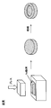
- a powder sintering method as shown in FIG. 5, first, a magnetic powder obtained by pulverizing raw materials by a jet mill (dry pulverization) is manufactured. Thereafter, the magnet powder is put into a mold and pressed into a desired shape while applying a magnetic field from the outside. Then, the solid magnet powder molded into a desired shape is manufactured by sintering at a predetermined temperature (for example, 1100 ° C. for Nd—Fe—B magnets).
- a predetermined temperature for example, 1100 ° C. for Nd—Fe—B magnets.
- JP 2006-286819 A (2nd page, 3rd page, FIG. 4) Japanese Patent Laid-Open No. 2004-250781 (pages 10 to 12, FIG. 2)
- the permanent magnet is manufactured by the above-described powder sintering method
- the powder sintering method it is necessary to ensure a certain porosity in the press-molded magnet powder for magnetic field orientation.
- magnet powder having a certain porosity is sintered, it is difficult to uniformly contract during the sintering, and deformation such as warpage and dent occurs after sintering.
- the sintered magnet can be dense and dense, and the magnet surface is distorted. Therefore, conventionally, it was necessary to compress the magnet powder in a size larger than the desired shape, assuming that the magnet surface can be distorted in advance. Then, after sintering, a diamond cutting and polishing operation is performed to correct the shape into a desired shape. As a result, the number of manufacturing steps increases, and the quality of the manufactured permanent magnet may decrease.
- permanent magnets used in VCM are required to be thin (for example, 1 mm or less in thickness). And the magnet made into a thin film has a large ratio of the surface degradation layer produced when the surface is processed compared with the magnet with thickness. Therefore, if a thin film-like permanent magnet is manufactured by the above-described powder sintering method, there is a problem that the magnetic properties are further deteriorated.
- the magnetic performance of the permanent magnet is basically improved if the crystal grain size of the sintered body is made fine because the magnetic property of the magnet is derived by the single domain fine particle theory. . Generally, if the crystal grain size of the sintered body is 3 ⁇ m or less, the magnetic performance can be sufficiently improved.
- the crystal grain size of the sintered body in order to reduce the crystal grain size of the sintered body, it is necessary to reduce the grain size of the magnet raw material before sintering.
- the magnet raw material finely pulverized to a particle size of 3 ⁇ m or less is molded and sintered, grain growth of magnet particles occurs during sintering, so the crystal grain size of the sintered body after sintering could not be 3 ⁇ m or less.
- a method of adding a material that suppresses the grain growth of the magnet particles (hereinafter referred to as a grain growth inhibitor) to the magnet raw material before sintering can be considered.
- the surface of magnet particles before sintering is coated with a particle growth inhibitor such as a metal compound having a melting point higher than the sintering temperature, thereby suppressing the particle growth of the magnet particles during sintering.
- a particle growth inhibitor such as a metal compound having a melting point higher than the sintering temperature
- the grain growth inhibitor is added to the magnet powder in advance by adding the grain growth inhibitor in the magnet raw material ingot as in Patent Document 2, the grain growth inhibitor is positioned on the surface of the magnet particle after sintering. Without diffusion into the magnet particles. As a result, it has been impossible to sufficiently suppress grain growth during sintering, and the residual magnetization of the magnet is reduced.
- the present invention has been made to solve the above-described conventional problems, and by making a green sheet, the shrinkage due to sintering becomes uniform, so that deformation such as warping and dent after sintering does not occur, Since there is no pressure unevenness during pressing, there is no need for correction processing after sintering, the manufacturing process can be simplified, and an organic compound or high melting point containing a refractory metal element on the surface of the magnet raw material By covering the ceramic precursor, it is possible to suppress the grain growth of the magnet particles during the sintering, and thus the permanent magnet capable of improving the magnetic performance by setting the crystal grain size of the sintered body to 3 ⁇ m or less, and An object is to provide a method for manufacturing a permanent magnet.
- the present invention relates to the following (1) to (5).
- An organic compound containing a refractory metal element or a precursor of a refractory ceramic is wet pulverized in a solvent together with a magnet raw material, the magnet raw material is pulverized into fine particles having a particle size of 3 ⁇ m or less, and the pulverized magnet raw material Coating the surface with an organic compound containing a refractory metal element or a precursor of a refractory ceramic; Adding a resin binder to a magnet raw material coated with an organic compound containing a refractory metal element or a precursor of a refractory ceramic; Producing a slurry by kneading the magnet raw material and the resin binder; Forming the slurry into a sheet and producing a green sheet; And a step of sintering the green sheet.
- the “organic compound containing a refractory metal element” means an ionic bond and / or a covalent bond and / or a coordination via an atom of a normal organic compound such as carbon, nitrogen, oxygen, sulfur, and phosphorus.
- a precursor of an organic compound or high melting point ceramic containing a refractory metal element is wet-mixed in a solvent together with the pulverized magnet raw material, and an organic compound or high melting point containing the refractory metal element on the surface of the pulverized magnet raw material Coating a ceramic precursor; Adding a resin binder to a magnet raw material coated with an organic compound containing a refractory metal element or a precursor of a refractory ceramic; Producing a slurry by kneading the magnet raw material and the resin binder; Forming the slurry into a sheet and producing a green sheet; And a step of sintering the green sheet.
- a precursor of an organic compound or high melting point ceramic containing a refractory metal element is wet-mixed in a solvent together with the pulverized magnet raw material, and an organic compound or high melting point containing the refractory metal element on the surface of the pulverized magnet raw material Coating a ceramic precursor; Adding a resin binder to a magnet raw material coated with an organic compound containing a refractory metal element or a precursor of a refractory ceramic; Producing a slurry by kneading the magnet raw material and the resin binder; Forming the slurry into a sheet and producing a green sheet; And a step of sintering the green sheet.
- the permanent magnet is composed of a magnet obtained by sintering a green sheet obtained by mixing and molding a magnet raw material and a resin binder. Deformation such as warping and dent after sintering does not occur, and pressure unevenness at the time of pressing is eliminated, so there is no need for conventional post-sintering correction processing, and the manufacturing process can be simplified. it can. Thereby, a permanent magnet can be formed with high dimensional accuracy. Further, even when the permanent magnet is thinned, the magnetic properties are not deteriorated by the processing deteriorated layer on the surface.
- an organic compound containing a refractory metal element or a precursor of a refractory ceramic coats the surface of the pulverized magnet particles, thereby suppressing the grain growth of the magnet particles during sintering. it can. Accordingly, it is possible to improve the magnetic performance by setting the crystal grain size of the sintered body to 3 ⁇ m or less.
- the permanent magnet described in (2) since the permanent magnet is composed of a magnet obtained by sintering a green sheet obtained by mixing and molding a magnet raw material and a resin binder, the shrinkage due to sintering becomes uniform. Because there is no deformation such as warping or dent after sintering, and pressure unevenness at the time of pressing is eliminated, there is no need for correction processing after sintering, which has been done conventionally, and the manufacturing process is simplified Can do. Thereby, a permanent magnet can be formed with high dimensional accuracy. Further, even when the permanent magnet is thinned, the magnetic properties are not deteriorated by the processing deteriorated layer on the surface.
- an organic compound containing a refractory metal element or a precursor of a refractory ceramic coats the surface of the pulverized magnet particles, thereby suppressing the grain growth of the magnet particles during sintering. it can. Accordingly, it is possible to improve the magnetic performance by setting the crystal grain size of the sintered body to 3 ⁇ m or less.
- the precursor of the organic compound or refractory ceramic containing the refractory metal element is unevenly distributed at the grain boundary of the magnet raw material after sintering, the residual magnetization of the magnet is reduced. Without making it possible, grain growth of the magnet particles during sintering can be suppressed.
- a permanent magnet is produced by mixing a green raw material and a resin binder and sintering a molded green sheet.
- deformation such as warping and dent after sintering does not occur, and pressure unevenness at the time of pressing is eliminated.
- a permanent magnet can be formed with high dimensional accuracy. Further, even when the permanent magnet is thinned, the magnetic properties are not deteriorated by the processing deteriorated layer on the surface.
- an organic compound containing a refractory metal element or a precursor of a refractory ceramic coats the surface of the pulverized magnet particles, thereby suppressing the grain growth of the magnet particles during sintering. it can. Therefore, it becomes possible to manufacture a permanent magnet having a crystal grain size of 3 ⁇ m or less and improved magnetic performance.
- a permanent magnet is produced by mixing a green raw material and a resin binder and sintering a molded green sheet.
- deformation such as warping and dent after sintering does not occur, and pressure unevenness at the time of pressing is eliminated.
- a permanent magnet can be formed with high dimensional accuracy. Further, even when the permanent magnet is thinned, the magnetic properties are not deteriorated by the processing deteriorated layer on the surface.
- an organic compound containing a refractory metal element or a precursor of a refractory ceramic coats the surface of the pulverized magnet particles, thereby suppressing the grain growth of the magnet particles during sintering. it can. Therefore, it becomes possible to manufacture a permanent magnet having a crystal grain size of 3 ⁇ m or less and improved magnetic performance.
- the permanent magnet 1 is an Nd—Fe—B based magnet.
- an organic compound containing a refractory metal element or a precursor of a refractory ceramic for suppressing grain growth during sintering of the permanent magnet 1 is added.
- each component is Nd: 27 to 30 wt%, metal component contained in an organic compound containing a refractory metal element (or ceramic component contained in a precursor of a refractory ceramic): 0.01 to 8 wt%, B : 1 to 2 wt%, Fe (electrolytic iron): 60 to 70 wt%.
- the permanent magnet 1 is a fan-shaped and thin-film magnet as shown in FIG.
- FIG. 1 is an overall view showing a permanent magnet 1 according to the present embodiment.
- the permanent magnet 1 is a thin-film permanent magnet having a thickness of 0.1 mm to 2 mm (2 mm in FIG. 1). And it produces by sintering the green sheet shape
- the permanent magnet 1 has a precursor layer 36 of an organic compound or refractory ceramic containing a refractory metal element on the surface of Nd magnet particles 35 constituting the permanent magnet 1 ( Hereinafter, the grain growth suppression layer 36) is coded.
- the particle size of the Nd magnet particles 35 is 3 ⁇ m or less.
- FIG. 2 is an enlarged view showing Nd magnet particles constituting the permanent magnet 1.
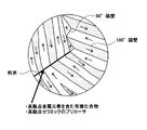
- FIG. 3 is a schematic diagram showing a magnetic domain structure of a ferromagnetic material.
- a grain boundary which is a discontinuous boundary surface left between a crystal and another crystal, has excessive energy, grain boundary movement that attempts to reduce energy occurs at a high temperature. Therefore, when the magnet raw material is sintered at a high temperature (for example, 1100 ° C. to 1150 ° C. for Nd—Fe—B magnets), the small magnet particles shrink and disappear, and the average particle size of the remaining magnet particles increases. So-called grain growth occurs.
- a trace amount for example, the metal or ceramic component contained in the organic compound is 0.01 to 8 wt% with respect to the magnet powder.
- Amount of an organic compound containing a refractory metal element or a precursor or dispersant of a refractory ceramic. Accordingly, when a magnetic powder containing a high-melting-point metal element or a high-melting-point ceramic precursor is subsequently sintered, the organic compound containing the high-melting-point metal element on the surface of the Nd magnet particles 35 by wet dispersion.
- a precursor of a high melting point ceramic is uniformly attached to form the grain growth suppression layer 36 shown in FIG.
- the melting point of the precursor of the organic compound containing the high melting point metal element or the high melting point ceramic is much higher than the sintering temperature of the magnet raw material (for example, 1100 ° C. to 1150 ° C. for Nd—Fe—B magnets), It is possible to prevent the organic compound containing the high melting point metal element or the precursor of the high melting point ceramic from diffusing and penetrating (solid solution) into the Nd magnet particle 35 during sintering. As a result, as shown in FIG.
- an organic compound containing a refractory metal element or a precursor of a refractory ceramic is unevenly distributed at the interface of the magnet particles. And the movement of the grain boundary which generate
- the magnetic performance of the permanent magnet is basically improved if the crystal grain size of the sintered body is made fine because the magnetic property of the magnet is derived by the single domain fine particle theory. .
- the crystal grain size of the sintered body is 3 ⁇ m or less, the magnetic performance can be sufficiently improved.
- the grain growth suppressing layer 36 can suppress the grain growth of the Nd magnet particles 35 during sintering, so that the grain size of the magnet raw material before sintering should be 3 ⁇ m or less.
- the particle diameter of the Nd magnet particles 35 of the permanent magnet 1 after sintering can be 3 ⁇ m or less.
- the precursor of the organic compound containing the high melting point metal element or the high melting point ceramic is diffused into the magnet particles 35 as described above. Infiltration (solid solution) can be prevented.
- a precursor of an organic compound containing a refractory metal element or a refractory ceramic diffuses and penetrates into the magnet particle 35, the remanent magnetization (magnetization when the magnetic field strength is reduced to 0) decreases. It has been known. Therefore, in this embodiment, it can prevent that the residual magnetization of the permanent magnet 1 falls.
- the grain growth suppression layer 36 does not have to be a layer composed only of an organic compound containing a refractory metal element or a precursor of a refractory ceramic, but an organic compound containing a refractory metal element or a precursor of a refractory ceramic and Nd. It may be a layer made of a mixture of In that case, a layer made of a mixture of an organic compound containing a refractory metal element or a precursor of a refractory ceramic and an Nd compound is formed by adding the Nd compound. As a result, liquid phase sintering during the sintering of the Nd magnet powder can be promoted.
- the Nd compound to be added includes neodymium acetate hydrate, neodymium (III) acetylacetonate trihydrate, neodymium (III) 2-ethylhexanoate, neodymium (III) hexafluoroacetylacetonate dihydrate.
- Neodymium isopropoxide, neodynium (III) phosphate n hydrate, neodymium trifluoroacetylacetonate, neodymium trifluoromethanesulfonate, and the like are desirable.
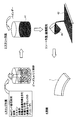
- FIG. 4 is an explanatory view showing a manufacturing process of the permanent magnet 1 according to the present embodiment.
- an ingot made of Nd 27-30% -Fe 60-70% -B1-2% in wt% is manufactured. Thereafter, the ingot is roughly pulverized to a size of about 200 ⁇ m by a stamp mill or a crusher.
- the coarsely pulverized magnet powder is finely pulverized to an average particle size of 3 ⁇ m or less by a wet method using a bead mill, and the magnet powder is dispersed in the solution to produce a slip.
- the wet pulverization 4 kg of toluene is used as a solvent with respect to 5 kg of the magnet powder, and 0.05 kg of a phosphate ester dispersant is added as a dispersant.
- an organic compound containing a refractory metal element in which the metal component contained is 0.01 to 8 wt% with respect to the magnet powder during the wet pulverization, or the ceramic component contained is 0.01 to Add a high melting point ceramic precursor to 8 wt%.
- an organic compound containing a refractory metal element or a precursor of a refractory ceramic is dispersed in a solvent together with the magnet powder.
- Detailed dispersion conditions are as follows. ⁇ Dispersion equipment: Bead mill ⁇ Dispersion media: Zirconia beads
- an organic compound of Ta, Mo, W, or Nb or a precursor of BN or AlN is used, and more specifically, tantalum.
- V Ethoxide, Tantalum (V) Methoxide, Tantalum (V) Tetraethoxyacetylacetonate, Tantalum (V) (Tetraethoxy) [BREW], Tantalum (V) Trifluoroethoxide, Tantalum (V) 2, 2, 2-trifluoroethoxide, tantalum tris (diethylamide) -t-butylimide, tungsten (VI) ethoxide, hexacarbonyltungsten, 12 tungsto (VI) phosphoric acid n hydrate, tungsto silicic acid n hydrate, 12 tungsto ( VI) Silicic acid 26 water, niobium n-butoxide, niobium chloride
- an organic compound containing a refractory metal element pulverized into fine particles or a precursor of a refractory ceramic can be added during wet dispersion and uniformly dispersed on the surface of Nd magnet particles by uniform dispersion. It becomes.
- the solvent used for pulverization is not particularly limited, and alcohols such as isopropyl alcohol, ethanol and methanol, lower hydrocarbons such as pentane and hexane, aromatics such as benzene, toluene and xylene, ketones, and the like. Although a mixture etc. can be used, isopropyl alcohol etc. are especially preferable.
- the material used as the resin binder is not particularly limited, and may be various thermoplastic resins alone or a mixture, or various thermosetting resins alone or a mixture, and desired physical properties and properties can be obtained. Anything within the range is acceptable. For example, there is a methacrylic resin.
- a green sheet 42 is formed from the generated slurry 41.
- the produced slurry 41 can be applied by an appropriate method on a support substrate such as a separator and dried as necessary.
- the coating method is preferably a method excellent in layer thickness controllability such as a doctor blade method. Further, it is preferable to sufficiently defoam the mixture so that bubbles do not remain in the spreading layer by using an antifoaming agent in combination.
- Detailed coating conditions are as follows. ⁇ Coating method: Doctor blade ⁇ Gap: 1mm Support substrate: Silicone-treated polyester film Drying conditions: 90 ° C x 10 minutes, then 130 ° C x 30 minutes
- a pulsed magnetic field is applied to the green sheet 42 coated on the support base in a direction that intersects the transport direction. Thereby orienting the magnetic field in the desired direction. Note that the direction in which the magnetic field is oriented needs to be determined in consideration of the magnetic field direction required for the permanent magnet 1 formed from the green sheet 42.
- the green sheet 42 formed from the slurry 41 is divided into a desired product shape (for example, a fan shape shown in FIG. 1 in this embodiment). Thereafter, sintering is performed at 1100 to 1150 ° C. for about 1 hour. In addition, sintering is performed in Ar or a vacuum atmosphere. And the permanent magnet 1 which consists of a sheet-like magnet is manufactured as a result of sintering.
- the magnet raw material composed of Nd 27-30% -Fe 60-70% -B 1-2% in wt% is 3 ⁇ m or less in particle size.
- An organic compound containing a refractory metal element in which the metal component contained in the magnet powder is 0.01 to 8 wt% during the wet pulverization, or a ceramic component contained in the magnet powder By adding a precursor of high melting point ceramic and a dispersing agent having a content of 0.01 to 8 wt%, an organic compound containing a high melting point metal element or a precursor of high melting point ceramic is dispersed in a solvent together with the magnet raw material.
- the permanent magnet 1 is manufactured by sintering the green sheet 42 which shape
- pressure unevenness during pressing is eliminated, there is no need to perform post-sintering correction processing, which has been conventionally performed, and the manufacturing process can be simplified. Thereby, the permanent magnet 1 can be molded with high dimensional accuracy.
- the magnetic properties of the permanent magnet 1 are not deteriorated due to the processing deteriorated layer on the surface.
- organic particles containing a refractory metal element mixed with magnet powder in a solvent or a precursor of a refractory ceramic is coated on the surface of the pulverized magnet particles, so that the particle growth of the magnet particles during sintering is achieved. Can be suppressed. Therefore, the crystal grain size of the sintered body can be 3 ⁇ m or less, and the magnetic performance of the permanent magnet can be improved.
- the precursor of the organic compound or refractory ceramic containing the refractory metal element is unevenly distributed at the grain boundary of the magnet raw material after sintering, the grain growth of the magnet particles during the sintering can be achieved without reducing the residual magnetization of the magnet. Can be suppressed.
- this invention is not limited to the said Example, Of course, various improvement and deformation
- a method of dispersing a magnet powder, an organic compound containing a refractory metal element or a precursor of a refractory ceramic in a solvent the magnet powder coarsely pulverized as shown in FIG.
- it is dispersed in a solvent by wet pulverization in a solvent together with an organic compound or a high melting point ceramic precursor, it can also be carried out by the following method.
- the coarsely pulverized magnet powder is finely pulverized into a magnet powder having an average particle size of 3 ⁇ m or less by dry pulverization using a ball mill, a jet mill or the like.
- the finely pulverized magnet powder is added to a solvent and uniformly dispersed in the solvent.
- a dispersant, an organic compound containing a refractory metal element, or a precursor of a refractory ceramic is also added to the solvent.
- the magnetic powder dispersed in the solvent and the resin binder are kneaded to generate the slurry 41. Thereafter, by performing the same processing as in the present embodiment, it becomes possible to manufacture a permanent magnet having the same configuration as in the present embodiment.
- the permanent magnet embedded in the VCM is described as an example.
- the vibration motor mounted on the mobile phone the drive motor mounted on the hybrid car, and the spindle that rotates the disk of the hard disk drive.
- the present invention can be applied to a permanent magnet embedded in a permanent magnet motor such as a motor.
- the pulverizing conditions, kneading conditions, sintering conditions, etc. of the magnet powder are not limited to the conditions described in the above examples.
- the permanent magnet of the present invention since it is configured as described above, deformation due to sintering becomes uniform and deformation such as warping and dent after sintering does not occur, and pressure unevenness during pressing is eliminated. There is no need to perform post-sintering correction processing that has been conventionally performed, and the manufacturing process can be simplified. Thereby, a permanent magnet can be formed with high dimensional accuracy. Further, even when the permanent magnet is thinned, the magnetic properties are not deteriorated by the processing deteriorated layer on the surface.
- an organic compound containing a refractory metal element or a precursor of a refractory ceramic coats the surface of the pulverized magnet particles, thereby suppressing the grain growth of the magnet particles during sintering. it can. Accordingly, it is possible to improve the magnetic performance by setting the crystal grain size of the sintered body to 3 ⁇ m or less.
Landscapes
- Engineering & Computer Science (AREA)
- Chemical & Material Sciences (AREA)
- Power Engineering (AREA)
- Mechanical Engineering (AREA)
- Crystallography & Structural Chemistry (AREA)
- Inorganic Chemistry (AREA)
- Manufacturing & Machinery (AREA)
- Materials Engineering (AREA)
- Metallurgy (AREA)
- Organic Chemistry (AREA)
- Hard Magnetic Materials (AREA)
- Powder Metallurgy (AREA)
- Manufacturing Cores, Coils, And Magnets (AREA)
- Permanent Field Magnets Of Synchronous Machinery (AREA)
Abstract
Description
そして、上記VCMにおいて小型化、薄型化を実現するに当たって、VCMに埋設される永久磁石について、薄膜化と更なる磁気特性の向上が求められている。尚、永久磁石としてはフェライト磁石、Sm-Co系磁石、Nd-Fe-B系磁石、Sm2Fe17Nx系磁石等があるが、特に保磁力の高いNd-Fe-B系磁石が永久磁石モータ用の永久磁石として用いられる。
(1)高融点金属元素を含む有機化合物又は高融点セラミックのプリカーサを磁石原料と共に溶媒中で湿式粉砕し、前記磁石原料を粒径が3μm以下の微粒子に粉砕するとともに前記粉砕された磁石原料の表面に前記高融点金属元素を含む有機化合物又は高融点セラミックのプリカーサを被覆する工程と、
前記高融点金属元素を含む有機化合物又は高融点セラミックのプリカーサが被覆された磁石原料に樹脂バインダーを添加する工程と、
前記磁石原料と前記樹脂バインダーとを混練することによりスラリーを生成する工程と、
前記スラリーをシート状に成形し、グリーンシートを作製する工程と、
前記グリーンシートを焼結する工程と、により製造される永久磁石。
尚、「高融点金属元素を含む有機化合物」とは、炭素、窒素、酸素、硫黄、燐など、通常の有機化合物が有する原子を介して、イオン結合、及び又は、共有結合、及び又は、配位結合を形成した高融点金属原子、又は高融点金属イオンを含む化合物をいう。
(2)磁石原料を粒径が3μm以下の微粒子に粉砕する工程と、
高融点金属元素を含む有機化合物又は高融点セラミックのプリカーサを前記粉砕された磁石原料と共に溶媒中で湿式混合し、前記粉砕された磁石原料の表面に前記高融点金属元素を含む有機化合物又は高融点セラミックのプリカーサを被覆する工程と、
前記高融点金属元素を含む有機化合物又は高融点セラミックのプリカーサが被覆された磁石原料に樹脂バインダーを添加する工程と、
前記磁石原料と前記樹脂バインダーとを混練することによりスラリーを生成する工程と、
前記スラリーをシート状に成形し、グリーンシートを作製する工程と、
前記グリーンシートを焼結する工程と、により製造される永久磁石。
(3)前記高融点金属元素を含む有機化合物又は高融点セラミックのプリカーサが、焼結後に前記磁石原料の粒界に偏在している(1)又は(2)に記載の永久磁石。
(4)高融点金属元素を含む有機化合物又は高融点セラミックのプリカーサを磁石原料と共に溶媒中で湿式粉砕し、前記磁石原料を粒径が3μm以下の微粒子に粉砕するとともに前記粉砕された磁石原料の表面に前記高融点金属元素を含む有機化合物又は高融点セラミックのプリカーサを被覆する工程と、
前記高融点金属元素を含む有機化合物又は高融点セラミックのプリカーサが被覆された磁石原料に樹脂バインダーを添加する工程と、
前記磁石原料と前記樹脂バインダーとを混練することによりスラリーを生成する工程と、
前記スラリーをシート状に成形し、グリーンシートを作製する工程と、
前記グリーンシートを焼結する工程と、を含む永久磁石の製造方法。
(5)磁石原料を粒径が3μm以下の微粒子に粉砕する工程と、
高融点金属元素を含む有機化合物又は高融点セラミックのプリカーサを前記粉砕された磁石原料と共に溶媒中で湿式混合し、前記粉砕された磁石原料の表面に前記高融点金属元素を含む有機化合物又は高融点セラミックのプリカーサを被覆する工程と、
前記高融点金属元素を含む有機化合物又は高融点セラミックのプリカーサが被覆された磁石原料に樹脂バインダーを添加する工程と、
前記磁石原料と前記樹脂バインダーとを混練することによりスラリーを生成する工程と、
前記スラリーをシート状に成形し、グリーンシートを作製する工程と、
前記グリーンシートを焼結する工程と、を含む永久磁石の製造方法。
また、湿式混合を行うことにより、高融点金属元素を含む有機化合物又は高融点セラミックのプリカーサが粉砕された磁石粒子の表面に被覆するので、焼結時の磁石粒子の粒成長を抑制することができる。従って、焼結体の結晶粒径を3μm以下とし、磁気性能を向上させることが可能となる。
また、湿式混合を行うことにより、高融点金属元素を含む有機化合物又は高融点セラミックのプリカーサが粉砕された磁石粒子の表面に被覆するので、焼結時の磁石粒子の粒成長を抑制することができる。従って、焼結体の結晶粒径を3μm以下とし、磁気性能を向上させることが可能となる。
また、湿式混合を行うことにより、高融点金属元素を含む有機化合物又は高融点セラミックのプリカーサが粉砕された磁石粒子の表面に被覆するので、焼結時の磁石粒子の粒成長を抑制することができる。従って、焼結体の結晶粒径を3μm以下とし、磁気性能を向上させた永久磁石を製造することが可能となる。
また、湿式混合を行うことにより、高融点金属元素を含む有機化合物又は高融点セラミックのプリカーサが粉砕された磁石粒子の表面に被覆するので、焼結時の磁石粒子の粒成長を抑制することができる。従って、焼結体の結晶粒径を3μm以下とし、磁気性能を向上させた永久磁石を製造することが可能となる。
先ず、図1~図3を用いて永久磁石1の構成について説明する。尚、本実施形態では特にVCMに埋設される永久磁石1を例に挙げて説明する。
本実施形態に係る永久磁石1はNd-Fe-B系磁石である。また、永久磁石1の焼結時における粒成長を抑制する為の高融点金属元素を含む有機化合物又は高融点セラミックのプリカーサが添加されている。尚、各成分の含有量はNd:27~30wt%、高融点金属元素を含む有機化合物に含まれる金属成分(又は高融点セラミックのプリカーサに含まれるセラミック成分):0.01~8wt%、B:1~2wt%、Fe(電解鉄):60~70wt%とする。また、永久磁石1は、図1に示すように扇形で且つ薄膜状の磁石から構成される。図1は本実施形態に係る永久磁石1を示した全体図である。
その結果、図3に示すように磁石粒子の界面に高融点金属元素を含む有機化合物又は高融点セラミックのプリカーサが偏在化される。そして、この偏在化された高融点金属元素を含む有機化合物又は高融点セラミックのプリカーサにより、高温時に発生する粒界の移動が妨げられ、粒成長を抑制することができる。
また、本実施形態では湿式成形により成形された磁石粉末を適切な焼成条件で焼成すれば、前記したように高融点金属元素を含む有機化合物又は高融点セラミックのプリカーサが磁石粒子35内へと拡散浸透(固溶化)することを防止できる。ここで、高融点金属元素を含む有機化合物又は高融点セラミックのプリカーサが磁石粒子35内へと拡散浸透すると、その磁石の残留磁化(磁場の強さを0にしたときの磁化)が低下することが知られている。従って、本実施形態では、永久磁石1の残留磁化が低下することを防止できる。
尚、粒成長抑制層36は高融点金属元素を含む有機化合物又は高融点セラミックのプリカーサのみから構成される層である必要はなく、高融点金属元素を含む有機化合物又は高融点セラミックのプリカーサとNdとの混合体からなる層であっても良い。その場合には、Nd化合物を添加することによって、高融点金属元素を含む有機化合物又は高融点セラミックのプリカーサとNd化合物との混合体からなる層を形成する。その結果、Nd磁石粉末の焼結時の液相焼結を助長することができる。尚、添加するNd化合物としては、酢酸ネオジム水和物、ネオジム(III)アセチルアセトナート三水和物、2-エチルヘキサン酸ネオジム(III)、ネオジム(III)ヘキサフルオロアセチルアセトナート二水和物、ネオジムイソプロポキシド、リン酸ネオジニウム(III)n水和物、ネオジムトリフルオロアセチルアセトナート、トリフルオロメタンスルホン酸ネオジム等が望ましい。
次に、本実施形態に係る永久磁石1の製造方法について図4を用いて説明する。図4は本実施形態に係る永久磁石1の製造工程を示した説明図である。
・分散装置:ビーズミル
・分散メディア:ジルコニアビーズ
また、溶媒に非可溶でも、微粒子に粉砕した高融点金属元素を含む有機化合物又は高融点セラミックのプリカーサを湿式分散時に添加し、均一分散する事でNd磁石粒子表面に均一付着させることが可能となる。
・塗工方式:ドクターブレード
・ギャップ:1mm
・支持基材:シリコーン処理ポリエステルフィルム
・乾燥条件:90℃×10分の後、130℃×30分
また、溶媒中で磁石粉末と共に湿式混合された高融点金属元素を含む有機化合物又は高融点セラミックのプリカーサが、粉砕された磁石粒子の表面に被覆することによって、焼結時の磁石粒子の粒成長を抑制することができる。従って、焼結体の結晶粒径を3μm以下とし、永久磁石の磁気性能を向上させることが可能となる。
また、高融点金属元素を含む有機化合物又は高融点セラミックのプリカーサが、焼結後に磁石原料の粒界に偏在するので、磁石の残留磁化を低下させることなく焼結時の磁石粒子の粒成長を抑制することができる。
例えば、本実施形態では磁石粉末や高融点金属元素を含む有機化合物又は高融点セラミックのプリカーサを溶媒中に分散させる方法として、図4に示すように粗粉砕した磁石粉末を、高融点金属元素を含む有機化合物又は高融点セラミックのプリカーサとともに溶媒中で湿式粉砕することにより溶媒中で分散させているが、以下の方法により行うことも可能である。
(1)先ず、粗粉砕した磁石粉末をボールミルやジェットミル等を用いて乾式粉砕により平均粒径が3μm以下の磁石粉末に微粉砕する。
(2)次に、微粉砕した磁石粉末を溶媒に添加し、溶媒中に均一に分散させる。その際、分散剤や高融点金属元素を含む有機化合物又は高融点セラミックのプリカーサについても溶媒中に添加する。
(3)溶媒中に分散された磁石粉末と樹脂バインダーを混練し、スラリー41を生成する。
以降は、本実施形態と同様の処理を行うことにより、本実施形態と同様の構成を備えた永久磁石を製造することが可能となる。
なお、本出願は、2008年4月15日付けで出願された日本特許出願(特願2008-105759)に基づいており、その全体が引用により援用される。
また、ここに引用されるすべての参照は全体として取り込まれる。
35 Nd磁石粒子
36 粒成長抑制層
41 スラリー
42 グリーンシート
Claims (5)
- 高融点金属元素を含む有機化合物又は高融点セラミックのプリカーサを磁石原料と共に溶媒中で湿式粉砕し、前記磁石原料を粒径が3μm以下の微粒子に粉砕するとともに前記粉砕された磁石原料の表面に前記高融点金属元素を含む有機化合物又は高融点セラミックのプリカーサを被覆する工程と、
前記高融点金属元素を含む有機化合物又は高融点セラミックのプリカーサが被覆された磁石原料に樹脂バインダーを添加する工程と、
前記磁石原料と前記樹脂バインダーとを混練することによりスラリーを生成する工程と、
前記スラリーをシート状に成形し、グリーンシートを作製する工程と、
前記グリーンシートを焼結する工程と、により製造される永久磁石。 - 磁石原料を粒径が3μm以下の微粒子に粉砕する工程と、
高融点金属元素を含む有機化合物又は高融点セラミックのプリカーサを前記粉砕された磁石原料と共に溶媒中で湿式混合し、前記粉砕された磁石原料の表面に前記高融点金属元素を含む有機化合物又は高融点セラミックのプリカーサを被覆する工程と、
前記高融点金属元素を含む有機化合物又は高融点セラミックのプリカーサが被覆された磁石原料に樹脂バインダーを添加する工程と、
前記磁石原料と前記樹脂バインダーとを混練することによりスラリーを生成する工程と、
前記スラリーをシート状に成形し、グリーンシートを作製する工程と、
前記グリーンシートを焼結する工程と、により製造される永久磁石。 - 前記高融点金属元素を含む有機化合物又は高融点セラミックのプリカーサが、焼結後に前記磁石原料の粒界に偏在している請求項1又は請求項2に記載の永久磁石。
- 高融点金属元素を含む有機化合物又は高融点セラミックのプリカーサを磁石原料と共に溶媒中で湿式粉砕し、前記磁石原料を粒径が3μm以下の微粒子に粉砕するとともに前記粉砕された磁石原料の表面に前記高融点金属元素を含む有機化合物又は高融点セラミックのプリカーサを被覆する工程と、
前記高融点金属元素を含む有機化合物又は高融点セラミックのプリカーサが被覆された磁石原料に樹脂バインダーを添加する工程と、
前記磁石原料と前記樹脂バインダーとを混練することによりスラリーを生成する工程と、
前記スラリーをシート状に成形し、グリーンシートを作製する工程と、
前記グリーンシートを焼結する工程と、を含む永久磁石の製造方法。 - 磁石原料を粒径が3μm以下の微粒子に粉砕する工程と、
高融点金属元素を含む有機化合物又は高融点セラミックのプリカーサを前記粉砕された磁石原料と共に溶媒中で湿式混合し、前記粉砕された磁石原料の表面に前記高融点金属元素を含む有機化合物又は高融点セラミックのプリカーサを被覆する工程と、
前記高融点金属元素を含む有機化合物又は高融点セラミックのプリカーサが被覆された磁石原料に樹脂バインダーを添加する工程と、
前記磁石原料と前記樹脂バインダーとを混練することによりスラリーを生成する工程と、
前記スラリーをシート状に成形し、グリーンシートを作製する工程と、
前記グリーンシートを焼結する工程と、を含む永久磁石の製造方法。
Priority Applications (4)
| Application Number | Priority Date | Filing Date | Title |
|---|---|---|---|
| CN2009801132984A CN102007555B (zh) | 2008-04-15 | 2009-04-14 | 永久磁铁和永久磁铁的制造方法 |
| KR1020107023113A KR101458255B1 (ko) | 2008-04-15 | 2009-04-14 | 영구 자석 및 영구 자석의 제조 방법 |
| US12/937,831 US8333848B2 (en) | 2008-04-15 | 2009-04-14 | Permanent magnet and process for producing permanent magnet |
| EP09731775A EP2273515A4 (en) | 2008-04-15 | 2009-04-14 | PERMANENT MAGNET AND PROCESS FOR MANUFACTURING A PERMANENT MAGNET |
Applications Claiming Priority (2)
| Application Number | Priority Date | Filing Date | Title |
|---|---|---|---|
| JP2008-105759 | 2008-04-15 | ||
| JP2008105759A JP5266522B2 (ja) | 2008-04-15 | 2008-04-15 | 永久磁石及び永久磁石の製造方法 |
Publications (1)
| Publication Number | Publication Date |
|---|---|
| WO2009128458A1 true WO2009128458A1 (ja) | 2009-10-22 |
Family
ID=41199147
Family Applications (1)
| Application Number | Title | Priority Date | Filing Date |
|---|---|---|---|
| PCT/JP2009/057530 Ceased WO2009128458A1 (ja) | 2008-04-15 | 2009-04-14 | 永久磁石及び永久磁石の製造方法 |
Country Status (6)
| Country | Link |
|---|---|
| US (1) | US8333848B2 (ja) |
| EP (1) | EP2273515A4 (ja) |
| JP (1) | JP5266522B2 (ja) |
| KR (1) | KR101458255B1 (ja) |
| CN (1) | CN102007555B (ja) |
| WO (1) | WO2009128458A1 (ja) |
Cited By (2)
| Publication number | Priority date | Publication date | Assignee | Title |
|---|---|---|---|---|
| JP2011216732A (ja) * | 2010-03-31 | 2011-10-27 | Nitto Denko Corp | 永久磁石及び永久磁石の製造方法 |
| JP2011216724A (ja) * | 2010-03-31 | 2011-10-27 | Nitto Denko Corp | 永久磁石及び永久磁石の製造方法 |
Families Citing this family (29)
| Publication number | Priority date | Publication date | Assignee | Title |
|---|---|---|---|---|
| TWI232595B (en) | 1999-06-04 | 2005-05-11 | Semiconductor Energy Lab | Electroluminescence display device and electronic device |
| JP2011216618A (ja) * | 2010-03-31 | 2011-10-27 | Nitto Denko Corp | 高保磁力異方性磁石及びその製造方法 |
| JP5501831B2 (ja) * | 2010-03-31 | 2014-05-28 | 日東電工株式会社 | 希土類磁石の製造方法 |
| JP2011216596A (ja) * | 2010-03-31 | 2011-10-27 | Nitto Denko Corp | 永久磁石及び永久磁石の製造方法 |
| JP5103553B1 (ja) * | 2011-06-24 | 2012-12-19 | 日東電工株式会社 | 希土類永久磁石及び希土類永久磁石の製造方法 |
| US20130141196A1 (en) * | 2011-06-24 | 2013-06-06 | Nitto Denko Corporation | Rare-earth permanent magnet and method for manufacturing rare-earth permanent magnet |
| KR101878998B1 (ko) | 2011-06-24 | 2018-07-16 | 닛토덴코 가부시키가이샤 | 희토류 영구 자석 및 희토류 영구 자석의 제조 방법 |
| JP5420700B2 (ja) * | 2011-06-24 | 2014-02-19 | 日東電工株式会社 | 希土類永久磁石及び希土類永久磁石の製造方法 |
| EP2685472A4 (en) * | 2011-06-24 | 2015-04-08 | Nitto Denko Corp | RARE EARTH PERMANENT MAGNET AND PROCESS FOR PRODUCING RARE EARTH PERMANENT MAGNET |
| WO2012176514A1 (ja) * | 2011-06-24 | 2012-12-27 | 日東電工株式会社 | 希土類永久磁石及び希土類永久磁石の製造方法 |
| US20130141194A1 (en) * | 2011-06-24 | 2013-06-06 | Nitto Denko Corporation | Rare-earth permanent magnet and method for manufacturing rare-earth permanent magnet |
| JP5420699B2 (ja) * | 2011-06-24 | 2014-02-19 | 日東電工株式会社 | 希土類永久磁石及び希土類永久磁石の製造方法 |
| JP5908246B2 (ja) * | 2011-09-30 | 2016-04-26 | 日東電工株式会社 | 希土類永久磁石の製造方法 |
| JP5908247B2 (ja) * | 2011-09-30 | 2016-04-26 | 日東電工株式会社 | 永久磁石の製造方法 |
| JP5878325B2 (ja) * | 2011-09-30 | 2016-03-08 | 日東電工株式会社 | 永久磁石の製造方法 |
| JP5969750B2 (ja) * | 2011-10-14 | 2016-08-17 | 日東電工株式会社 | 希土類永久磁石の製造方法 |
| JP5411956B2 (ja) | 2012-03-12 | 2014-02-12 | 日東電工株式会社 | 希土類永久磁石、希土類永久磁石の製造方法及び希土類永久磁石の製造装置 |
| JP2013191616A (ja) * | 2012-03-12 | 2013-09-26 | Nitto Denko Corp | 希土類永久磁石及び希土類永久磁石の製造方法 |
| JP2013191607A (ja) * | 2012-03-12 | 2013-09-26 | Nitto Denko Corp | 希土類永久磁石及び希土類永久磁石の製造方法 |
| DE102013004985A1 (de) | 2012-11-14 | 2014-05-15 | Volkswagen Aktiengesellschaft | Verfahren zur Herstellung eines Permanentmagneten sowie Permanentmagnet |
| CN105103249A (zh) * | 2013-03-25 | 2015-11-25 | 因太金属株式会社 | 烧结磁体制造方法 |
| DE102013213494A1 (de) | 2013-07-10 | 2015-01-29 | Volkswagen Aktiengesellschaft | Verfahren zur Herstellung eines Permanentmagneten sowie Permanentmagnet und elektrische Maschine mit einem solchen |
| CN104299768B (zh) * | 2014-11-09 | 2016-09-28 | 内蒙古科技大学 | 一种制备Sm-Co/Nd-Fe-B复合永磁材料的方法 |
| KR101661067B1 (ko) * | 2015-07-14 | 2016-09-29 | 한국세라믹기술원 | 금속 고분자 복합체 시트의 제조방법 |
| CN105895359A (zh) * | 2016-06-18 | 2016-08-24 | 丁文澜 | 一种各向异性永磁铁氧体多极磁环制造的方法 |
| CN106229102B (zh) * | 2016-08-23 | 2019-05-31 | 南京工程学院 | 一种超细晶NdFeB永磁材料及其制备方法 |
| CN106920615B (zh) * | 2017-03-08 | 2018-10-26 | 江苏南方永磁科技有限公司 | 一种烧结钕铁硼材料及制备方法 |
| CN110676044B (zh) * | 2019-09-10 | 2021-06-01 | 东莞艾宝纳米科技有限公司 | 一种高磁导率、低磁芯损耗的磁芯粉复合材料和磁环及其制备方法 |
| CN112071620B (zh) * | 2020-09-08 | 2021-12-21 | 包头市英思特稀磁新材料股份有限公司 | 一种永磁体合金材料的制备工艺 |
Citations (9)
| Publication number | Priority date | Publication date | Assignee | Title |
|---|---|---|---|---|
| JPS62284002A (ja) * | 1986-05-02 | 1987-12-09 | Tohoku Metal Ind Ltd | 希土類磁石合金粉末の製造方法 |
| JPH01150303A (ja) * | 1987-12-08 | 1989-06-13 | Mitsubishi Steel Mfg Co Ltd | 磁気異方性焼結磁石及びその製造方法 |
| JPH0314204A (ja) * | 1989-06-07 | 1991-01-22 | Ind Technol Res Inst | 希土類磁石製造方法 |
| JPH0426104A (ja) * | 1990-05-21 | 1992-01-29 | Isuzu Ceramics Kenkyusho:Kk | 希土類磁石とその製造方法 |
| JPH11307330A (ja) * | 1998-04-22 | 1999-11-05 | Sumitomo Special Metals Co Ltd | R−Fe−B系磁石の製造方法 |
| JP2002164239A (ja) * | 2000-09-14 | 2002-06-07 | Hitachi Metals Ltd | 希土類焼結磁石の製造方法およびリング磁石およびアークセグメント磁石 |
| JP2004250781A (ja) | 2002-10-08 | 2004-09-09 | Neomax Co Ltd | 焼結型永久磁石およびその製造方法 |
| JP2006286819A (ja) | 2005-03-31 | 2006-10-19 | Tdk Corp | 希土類焼結磁石及びそれを用いたvcm装置 |
| JP2008105759A (ja) | 2006-10-23 | 2008-05-08 | Yamato Scale Co Ltd | 整列コンベア用供給装置及びその運転方法、並びに箱詰め装置。 |
Family Cites Families (8)
| Publication number | Priority date | Publication date | Assignee | Title |
|---|---|---|---|---|
| US3892599A (en) * | 1973-06-22 | 1975-07-01 | Gen Electric | Air-stable compact of cobalt-rare earth alloy particles and method |
| US4776902A (en) * | 1984-03-30 | 1988-10-11 | Union Oil Company Of California | Method for making rare earth-containing magnets |
| JPS6468903A (en) * | 1987-09-09 | 1989-03-15 | Fuji Electrochemical Co Ltd | Manufacture of permanent magnet |
| CN1288679C (zh) * | 1998-04-22 | 2006-12-06 | 株式会社新王磁材 | 生产R-Fe-B磁体的方法和用于模压加工该磁体的润滑剂 |
| KR100379247B1 (ko) * | 2000-09-06 | 2003-04-08 | 한국과학기술연구원 | 희토류계 영구자석의 제조방법 |
| JP2004253697A (ja) * | 2003-02-21 | 2004-09-09 | Hitachi Metals Ltd | 永久磁石材料及び永久磁石 |
| US7390579B2 (en) * | 2003-11-25 | 2008-06-24 | Magnequench, Inc. | Coating formulation and application of organic passivation layer onto iron-based rare earth powders |
| JP2006207001A (ja) * | 2005-01-31 | 2006-08-10 | Alps Electric Co Ltd | 磁性複合シートの製造方法 |
-
2008
- 2008-04-15 JP JP2008105759A patent/JP5266522B2/ja not_active Expired - Fee Related
-
2009
- 2009-04-14 EP EP09731775A patent/EP2273515A4/en not_active Withdrawn
- 2009-04-14 US US12/937,831 patent/US8333848B2/en not_active Expired - Fee Related
- 2009-04-14 WO PCT/JP2009/057530 patent/WO2009128458A1/ja not_active Ceased
- 2009-04-14 KR KR1020107023113A patent/KR101458255B1/ko not_active Expired - Fee Related
- 2009-04-14 CN CN2009801132984A patent/CN102007555B/zh not_active Expired - Fee Related
Patent Citations (9)
| Publication number | Priority date | Publication date | Assignee | Title |
|---|---|---|---|---|
| JPS62284002A (ja) * | 1986-05-02 | 1987-12-09 | Tohoku Metal Ind Ltd | 希土類磁石合金粉末の製造方法 |
| JPH01150303A (ja) * | 1987-12-08 | 1989-06-13 | Mitsubishi Steel Mfg Co Ltd | 磁気異方性焼結磁石及びその製造方法 |
| JPH0314204A (ja) * | 1989-06-07 | 1991-01-22 | Ind Technol Res Inst | 希土類磁石製造方法 |
| JPH0426104A (ja) * | 1990-05-21 | 1992-01-29 | Isuzu Ceramics Kenkyusho:Kk | 希土類磁石とその製造方法 |
| JPH11307330A (ja) * | 1998-04-22 | 1999-11-05 | Sumitomo Special Metals Co Ltd | R−Fe−B系磁石の製造方法 |
| JP2002164239A (ja) * | 2000-09-14 | 2002-06-07 | Hitachi Metals Ltd | 希土類焼結磁石の製造方法およびリング磁石およびアークセグメント磁石 |
| JP2004250781A (ja) | 2002-10-08 | 2004-09-09 | Neomax Co Ltd | 焼結型永久磁石およびその製造方法 |
| JP2006286819A (ja) | 2005-03-31 | 2006-10-19 | Tdk Corp | 希土類焼結磁石及びそれを用いたvcm装置 |
| JP2008105759A (ja) | 2006-10-23 | 2008-05-08 | Yamato Scale Co Ltd | 整列コンベア用供給装置及びその運転方法、並びに箱詰め装置。 |
Non-Patent Citations (1)
| Title |
|---|
| See also references of EP2273515A4 |
Cited By (2)
| Publication number | Priority date | Publication date | Assignee | Title |
|---|---|---|---|---|
| JP2011216732A (ja) * | 2010-03-31 | 2011-10-27 | Nitto Denko Corp | 永久磁石及び永久磁石の製造方法 |
| JP2011216724A (ja) * | 2010-03-31 | 2011-10-27 | Nitto Denko Corp | 永久磁石及び永久磁石の製造方法 |
Also Published As
| Publication number | Publication date |
|---|---|
| KR20100136508A (ko) | 2010-12-28 |
| JP5266522B2 (ja) | 2013-08-21 |
| US8333848B2 (en) | 2012-12-18 |
| CN102007555A (zh) | 2011-04-06 |
| EP2273515A1 (en) | 2011-01-12 |
| KR101458255B1 (ko) | 2014-11-04 |
| JP2009259955A (ja) | 2009-11-05 |
| CN102007555B (zh) | 2013-01-09 |
| US20110037548A1 (en) | 2011-02-17 |
| EP2273515A4 (en) | 2011-05-18 |
Similar Documents
| Publication | Publication Date | Title |
|---|---|---|
| JP5266522B2 (ja) | 永久磁石及び永久磁石の製造方法 | |
| JP4872109B2 (ja) | 永久磁石及び永久磁石の製造方法 | |
| JP5417632B2 (ja) | 永久磁石及び永久磁石の製造方法 | |
| KR101458256B1 (ko) | 영구 자석 및 영구 자석의 제조 방법 | |
| JP2009225608A (ja) | モータ用永久磁石及びモータ用永久磁石の製造方法 | |
| WO2013054678A1 (ja) | 希土類永久磁石及び希土類永久磁石の製造方法 | |
| JP5298180B2 (ja) | モータ用永久磁石及びモータ用永久磁石の製造方法 | |
| JP5908247B2 (ja) | 永久磁石の製造方法 | |
| WO2011125593A1 (ja) | 永久磁石及び永久磁石の製造方法 | |
| JP2012004576A (ja) | 永久磁石及び永久磁石の製造方法 | |
| WO2011125584A1 (ja) | 永久磁石及び永久磁石の製造方法 | |
| WO2013047470A1 (ja) | 永久磁石及び永久磁石の製造方法 |
Legal Events
| Date | Code | Title | Description |
|---|---|---|---|
| WWE | Wipo information: entry into national phase |
Ref document number: 200980113298.4 Country of ref document: CN |
|
| 121 | Ep: the epo has been informed by wipo that ep was designated in this application |
Ref document number: 09731775 Country of ref document: EP Kind code of ref document: A1 |
|
| REEP | Request for entry into the european phase |
Ref document number: 2009731775 Country of ref document: EP |
|
| WWE | Wipo information: entry into national phase |
Ref document number: 12937831 Country of ref document: US Ref document number: 2009731775 Country of ref document: EP |
|
| ENP | Entry into the national phase |
Ref document number: 20107023113 Country of ref document: KR Kind code of ref document: A |
|
| NENP | Non-entry into the national phase |
Ref country code: DE |
|
| WWE | Wipo information: entry into national phase |
Ref document number: 6611/CHENP/2010 Country of ref document: IN |