WO2009128460A1 - 永久磁石及び永久磁石の製造方法 - Google Patents
永久磁石及び永久磁石の製造方法 Download PDFInfo
- Publication number
- WO2009128460A1 WO2009128460A1 PCT/JP2009/057532 JP2009057532W WO2009128460A1 WO 2009128460 A1 WO2009128460 A1 WO 2009128460A1 JP 2009057532 W JP2009057532 W JP 2009057532W WO 2009128460 A1 WO2009128460 A1 WO 2009128460A1
- Authority
- WO
- WIPO (PCT)
- Prior art keywords
- magnet
- permanent magnet
- compound
- raw material
- fine particles
- Prior art date
- Legal status (The legal status is an assumption and is not a legal conclusion. Google has not performed a legal analysis and makes no representation as to the accuracy of the status listed.)
- Ceased
Links
Images


Classifications
-
- H—ELECTRICITY
- H01—ELECTRIC ELEMENTS
- H01F—MAGNETS; INDUCTANCES; TRANSFORMERS; SELECTION OF MATERIALS FOR THEIR MAGNETIC PROPERTIES
- H01F41/00—Apparatus or processes specially adapted for manufacturing or assembling magnets, inductances or transformers; Apparatus or processes specially adapted for manufacturing materials characterised by their magnetic properties
- H01F41/02—Apparatus or processes specially adapted for manufacturing or assembling magnets, inductances or transformers; Apparatus or processes specially adapted for manufacturing materials characterised by their magnetic properties for manufacturing cores, coils, or magnets
- H01F41/0253—Apparatus or processes specially adapted for manufacturing or assembling magnets, inductances or transformers; Apparatus or processes specially adapted for manufacturing materials characterised by their magnetic properties for manufacturing cores, coils, or magnets for manufacturing permanent magnets
- H01F41/0266—Moulding; Pressing
-
- B—PERFORMING OPERATIONS; TRANSPORTING
- B22—CASTING; POWDER METALLURGY
- B22F—WORKING METALLIC POWDER; MANUFACTURE OF ARTICLES FROM METALLIC POWDER; MAKING METALLIC POWDER; APPARATUS OR DEVICES SPECIALLY ADAPTED FOR METALLIC POWDER
- B22F1/00—Metallic powder; Treatment of metallic powder, e.g. to facilitate working or to improve properties
- B22F1/10—Metallic powder containing lubricating or binding agents; Metallic powder containing organic material
-
- C—CHEMISTRY; METALLURGY
- C22—METALLURGY; FERROUS OR NON-FERROUS ALLOYS; TREATMENT OF ALLOYS OR NON-FERROUS METALS
- C22C—ALLOYS
- C22C38/00—Ferrous alloys, e.g. steel alloys
- C22C38/002—Ferrous alloys, e.g. steel alloys containing In, Mg, or other elements not provided for in one single group C22C38/001 - C22C38/60
-
- C—CHEMISTRY; METALLURGY
- C22—METALLURGY; FERROUS OR NON-FERROUS ALLOYS; TREATMENT OF ALLOYS OR NON-FERROUS METALS
- C22C—ALLOYS
- C22C38/00—Ferrous alloys, e.g. steel alloys
- C22C38/005—Ferrous alloys, e.g. steel alloys containing rare earths, i.e. Sc, Y, Lanthanides
-
- H—ELECTRICITY
- H01—ELECTRIC ELEMENTS
- H01F—MAGNETS; INDUCTANCES; TRANSFORMERS; SELECTION OF MATERIALS FOR THEIR MAGNETIC PROPERTIES
- H01F1/00—Magnets or magnetic bodies characterised by the magnetic materials therefor; Selection of materials for their magnetic properties
- H01F1/01—Magnets or magnetic bodies characterised by the magnetic materials therefor; Selection of materials for their magnetic properties of inorganic materials
- H01F1/03—Magnets or magnetic bodies characterised by the magnetic materials therefor; Selection of materials for their magnetic properties of inorganic materials characterised by their coercivity
- H01F1/032—Magnets or magnetic bodies characterised by the magnetic materials therefor; Selection of materials for their magnetic properties of inorganic materials characterised by their coercivity of hard-magnetic materials
- H01F1/04—Magnets or magnetic bodies characterised by the magnetic materials therefor; Selection of materials for their magnetic properties of inorganic materials characterised by their coercivity of hard-magnetic materials metals or alloys
- H01F1/047—Alloys characterised by their composition
- H01F1/053—Alloys characterised by their composition containing rare earth metals
- H01F1/055—Alloys characterised by their composition containing rare earth metals and magnetic transition metals, e.g. SmCo5
- H01F1/057—Alloys characterised by their composition containing rare earth metals and magnetic transition metals, e.g. SmCo5 and IIIa elements, e.g. Nd2Fe14B
- H01F1/0571—Alloys characterised by their composition containing rare earth metals and magnetic transition metals, e.g. SmCo5 and IIIa elements, e.g. Nd2Fe14B in the form of particles, e.g. rapid quenched powders or ribbon flakes
- H01F1/0572—Alloys characterised by their composition containing rare earth metals and magnetic transition metals, e.g. SmCo5 and IIIa elements, e.g. Nd2Fe14B in the form of particles, e.g. rapid quenched powders or ribbon flakes with a protective layer
-
- H—ELECTRICITY
- H01—ELECTRIC ELEMENTS
- H01F—MAGNETS; INDUCTANCES; TRANSFORMERS; SELECTION OF MATERIALS FOR THEIR MAGNETIC PROPERTIES
- H01F1/00—Magnets or magnetic bodies characterised by the magnetic materials therefor; Selection of materials for their magnetic properties
- H01F1/01—Magnets or magnetic bodies characterised by the magnetic materials therefor; Selection of materials for their magnetic properties of inorganic materials
- H01F1/03—Magnets or magnetic bodies characterised by the magnetic materials therefor; Selection of materials for their magnetic properties of inorganic materials characterised by their coercivity
- H01F1/032—Magnets or magnetic bodies characterised by the magnetic materials therefor; Selection of materials for their magnetic properties of inorganic materials characterised by their coercivity of hard-magnetic materials
- H01F1/04—Magnets or magnetic bodies characterised by the magnetic materials therefor; Selection of materials for their magnetic properties of inorganic materials characterised by their coercivity of hard-magnetic materials metals or alloys
- H01F1/047—Alloys characterised by their composition
- H01F1/053—Alloys characterised by their composition containing rare earth metals
- H01F1/055—Alloys characterised by their composition containing rare earth metals and magnetic transition metals, e.g. SmCo5
- H01F1/057—Alloys characterised by their composition containing rare earth metals and magnetic transition metals, e.g. SmCo5 and IIIa elements, e.g. Nd2Fe14B
- H01F1/0571—Alloys characterised by their composition containing rare earth metals and magnetic transition metals, e.g. SmCo5 and IIIa elements, e.g. Nd2Fe14B in the form of particles, e.g. rapid quenched powders or ribbon flakes
- H01F1/0575—Alloys characterised by their composition containing rare earth metals and magnetic transition metals, e.g. SmCo5 and IIIa elements, e.g. Nd2Fe14B in the form of particles, e.g. rapid quenched powders or ribbon flakes pressed, sintered or bonded together
- H01F1/0577—Alloys characterised by their composition containing rare earth metals and magnetic transition metals, e.g. SmCo5 and IIIa elements, e.g. Nd2Fe14B in the form of particles, e.g. rapid quenched powders or ribbon flakes pressed, sintered or bonded together sintered
-
- H—ELECTRICITY
- H01—ELECTRIC ELEMENTS
- H01F—MAGNETS; INDUCTANCES; TRANSFORMERS; SELECTION OF MATERIALS FOR THEIR MAGNETIC PROPERTIES
- H01F41/00—Apparatus or processes specially adapted for manufacturing or assembling magnets, inductances or transformers; Apparatus or processes specially adapted for manufacturing materials characterised by their magnetic properties
- H01F41/02—Apparatus or processes specially adapted for manufacturing or assembling magnets, inductances or transformers; Apparatus or processes specially adapted for manufacturing materials characterised by their magnetic properties for manufacturing cores, coils, or magnets
- H01F41/0253—Apparatus or processes specially adapted for manufacturing or assembling magnets, inductances or transformers; Apparatus or processes specially adapted for manufacturing materials characterised by their magnetic properties for manufacturing cores, coils, or magnets for manufacturing permanent magnets
- H01F41/0293—Apparatus or processes specially adapted for manufacturing or assembling magnets, inductances or transformers; Apparatus or processes specially adapted for manufacturing materials characterised by their magnetic properties for manufacturing cores, coils, or magnets for manufacturing permanent magnets diffusion of rare earth elements, e.g. Tb, Dy or Ho, into permanent magnets
-
- B—PERFORMING OPERATIONS; TRANSPORTING
- B22—CASTING; POWDER METALLURGY
- B22F—WORKING METALLIC POWDER; MANUFACTURE OF ARTICLES FROM METALLIC POWDER; MAKING METALLIC POWDER; APPARATUS OR DEVICES SPECIALLY ADAPTED FOR METALLIC POWDER
- B22F3/00—Manufacture of workpieces or articles from metallic powder characterised by the manner of compacting or sintering; Apparatus specially adapted therefor ; Presses and furnaces
- B22F3/02—Compacting only
- B22F2003/023—Lubricant mixed with the metal powder
-
- H—ELECTRICITY
- H01—ELECTRIC ELEMENTS
- H01F—MAGNETS; INDUCTANCES; TRANSFORMERS; SELECTION OF MATERIALS FOR THEIR MAGNETIC PROPERTIES
- H01F7/00—Magnets
- H01F7/02—Permanent magnets [PM]
Definitions
- the present invention relates to a permanent magnet and a method for manufacturing the permanent magnet.
- Permanent magnet motors used in hybrid cars, hard disk drives, and the like have been required to be smaller, lighter, higher in output, and more efficient.
- the permanent magnet embedded in the permanent magnet motor is required to be thin and further improve the magnetic characteristics.
- Permanent magnets include ferrite magnets, Sm—Co based magnets, Nd—Fe—B based magnets, Sm 2 Fe 17 N x based magnets, etc., but Nd—Fe—B based magnets with particularly high coercive force are permanent. Used as a permanent magnet for a magnet motor.
- a powder sintering method is generally used as a manufacturing method of the permanent magnet.
- the powder sintering method first, magnet powder obtained by pulverizing raw materials by a jet mill (dry pulverization) is manufactured. Thereafter, the magnet powder is put into a mold and pressed into a desired shape while applying a magnetic field from the outside. Then, the solid magnet powder formed into a desired shape is produced by sintering at a predetermined temperature (for example, 1100 ° C. to 1150 ° C. for Nd—Fe—B magnets).
- the powder sintering method usually when a raw material is finely pulverized by a jet mill, a small amount of oxygen is introduced into the jet mill, and the oxygen concentration in the nitrogen gas or Ar gas as a pulverization medium is controlled within a desired range. To do. This is because the surface of the magnet powder is forcibly oxidized, and the magnet powder finely pulverized without this oxidation treatment is ignited as soon as it is exposed to the atmosphere. However, most of the oxygen in the sintered body obtained by sintering the oxidized magnetic powder is combined with rare earth elements such as Nd and exists as oxides at the grain boundaries.
- Patent Document 1 Japanese Patent Application Laid-Open No. 2004-250781
- a rare earth magnet raw material is pulverized by a jet mill
- the pulverized magnet raw material is recovered in a rust preventive oil such as mineral oil or synthetic oil
- a manufacturing method is disclosed in which the slurry is wet-molded in a magnetic field while deoiling, the molded body is deoiled in vacuum and sintered.
- Nd-based magnets such as Nd-Fe-B are used for permanent magnet motors
- Dy dysprosium
- Dy is added to improve the output of the motor, and the coercive force of the magnet can be further improved. It has been. This is because Dy is solid-solved in the magnet particles.
- a large amount of Dy is required in order to solidify Dy in the magnet particles and sufficiently improve the coercive force of the magnet.
- the necessary amount of Dy added is 20-30 wt% with respect to Nd.
- Dy is a rare metal and the production area is limited, it is desirable to suppress the amount of Dy used for Nd as much as possible. Further, when the Dy added as described above is solid-solved in the magnet particles, the residual magnetization of the magnet is reduced. Therefore, a technique for greatly improving the coercive force of a magnet without reducing residual magnetization by a small amount of Dy has been desired.
- the present invention has been made to solve the above-mentioned problems, and by mixing the magnet raw material with the rust preventive oil, the pulverized magnet raw material can be prevented from being oxidized and dissolved in the mixed rust preventive oil.
- the small amount of Dy or Tb that is generated can be unevenly distributed at the grain boundaries of the magnet particles, and the residual magnetization and coercive force due to Dy and Tb can be sufficiently improved while reducing the amount of Dy and Tb used. It is an object of the present invention to provide a possible permanent magnet and a method for manufacturing the permanent magnet.
- the present invention relates to the following (1) to (10).
- the permanent magnet having the configuration of (1) it is possible to prevent the pulverized magnet raw material from being oxidized by mixing the magnetic raw material with rust preventive oil.
- a small amount of Dy compound or Tb compound dissolved in the mixed rust preventive oil can be unevenly distributed at the grain boundaries of the magnet particles, and the amount of Dy or Tb used can be reduced while maintaining the amount of Dy or Tb. It is possible to sufficiently improve the magnetic force. Further, it is possible to prevent Dy or Tb from forming a solid solution in the magnet particles and reducing the residual magnetization.
- the content of the Dy compound or Tb compound is 0.01 to 8 wt%, the amount of Dy or Tb is reduced while the amount of Dy or Tb is reduced. It is possible to sufficiently improve the remanent magnetization and the coercive force.
- the permanent magnet described in (4) above it is possible to prevent the pulverized magnet raw material from being oxidized by mixing the magnetic raw material with rust preventive oil.
- a small amount of Dy fine particles and Tb fine particles dissolved in the mixed rust preventive oil can be unevenly distributed at the grain boundaries of the magnet particles, and the amount of Dy or Tb used can be reduced while being retained by Dy or Tb. It is possible to sufficiently improve the magnetic force. Further, it is possible to prevent Dy or Tb from forming a solid solution in the magnet particles and reducing the residual magnetization.
- the Dy fine particles or the Tb fine particles are unevenly distributed at the grain boundaries of the magnet raw material after sintering, it is possible to reduce the amount of Dy or Tb while reducing the amount of Dy or Tb used. It becomes possible to sufficiently improve the coercive force due to Tb.
- the content of the Dy fine particles or Tb fine particles is 0.01 to 8 wt%, the amount of Dy or Tb is reduced while the amount of Dy or Tb is reduced. It is possible to sufficiently improve the remanent magnetization and the coercive force.
- oxidation of the pulverized magnet raw material can be prevented by mixing the magnetic raw material with rust preventive oil.
- a small amount of Dy compound or Tb compound dissolved in the mixed rust preventive oil can be unevenly distributed at the grain boundaries of the magnet particles, and the amount of Dy or Tb used can be reduced while maintaining the amount of Dy or Tb. It becomes possible to manufacture a permanent magnet with improved magnetic force. Further, it is possible to prevent Dy or Tb from forming a solid solution in the magnet particles and reducing the residual magnetization.
- the amount of Dy or Tb is reduced while the amount of Dy or Tb is used.
- oxidation of the pulverized magnet raw material can be prevented by mixing the magnetic raw material with antirust oil.
- a small amount of Dy fine particles and Tb fine particles dissolved in the mixed rust preventive oil can be unevenly distributed at the grain boundaries of the magnet particles, and the amount of Dy or Tb used can be reduced while being retained by Dy or Tb. It becomes possible to manufacture a permanent magnet with improved magnetic force. Further, it is possible to prevent Dy or Tb from forming a solid solution in the magnet particles and reducing the residual magnetization.
- the amount of Dy or Tb is reduced while the amount of Dy or Tb is used.
- the permanent magnet 1 is an Nd—Fe—B based magnet. Further, Dy (dysprosium) for increasing the coercive force of the permanent magnet 1 is added. The content of each component is Nd: 27 to 30 wt%, Dy component contained in the Dy compound (or Tb component contained in the Tb compound): 0.01 to 8 wt%, B: 1 to 2 wt%, Fe (electrolysis) Iron): 60 to 70 wt%.
- the permanent magnet 1 which concerns on this embodiment is provided with a column shape as shown in FIG. 1, the shape of the permanent magnet 1 changes with the shape of the cavity used for shaping
- FIG. 1 is an overall view showing a permanent magnet 1 according to the present embodiment.
- the permanent magnet 1 is compression-molded by drawing Nd magnet powder mixed with rust-preventing oil into a slurry state as described later into a cavity having a shape corresponding to the outer shape of the molded body to be molded. It is produced by sintering the molded body.
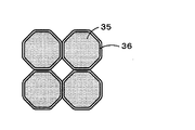
- the permanent magnet 1 improves the coercive force of the permanent magnet 1 by coding the Dy layer 36 on the surface of the Nd magnet particles 35 constituting the permanent magnet 1 as shown in FIG. Yes.
- FIG. 2 is an enlarged view showing Nd magnet particles constituting the permanent magnet 1.
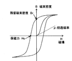
- FIG. 3 is a diagram showing a hysteresis curve of a ferromagnetic material
- FIG. 4 is a schematic diagram showing a magnetic domain structure of the ferromagnetic material.
- the coercive force of the permanent magnet is that of the magnetic field required to make the magnetic polarization zero (ie, reverse the magnetization) when a magnetic field is applied in the reverse direction from the magnetized state. It is strength. Therefore, if the magnetization reversal can be suppressed, a high coercive force can be obtained.
- the magnet powder when the magnet powder is finely pulverized by dry pulverization as described later, a small amount (for example, 0.01 to 8 wt% with respect to the magnet powder (addition amount of Dy to Nd, especially Dy In the case of adding a compound, the rust-preventing oil in which the Dy compound is dissolved) is mixed with the finely pulverized magnet powder.
- the Dy compound when the magnet powder mixed with the rust preventive oil is subsequently sintered, the Dy compound is uniformly adhered to the particle surfaces of the Nd magnet particles 35 to form the Dy layer 36 shown in FIG.
- Dy is unevenly distributed at the interface of the magnet particles, and the coercive force of the permanent magnet 1 can be improved.
- the compact formed by compression molding is fired under appropriate firing conditions, Dy can be prevented from diffusing and penetrating (solid solution) into the magnet particles 35.
- Dy can be prevented from diffusing and penetrating (solid solution) into the magnet particles 35.
- the Dy layer 36 does not need to be a layer composed only of the Dy compound, and may be a layer composed of a mixture of the Dy compound and the Nd compound. In that case, a layer made of a mixture of the Dy compound and the Nd compound is formed by adding the Nd compound.
- the Nd compound to be added includes neodymium acetate hydrate, neodymium (III) acetylacetonate trihydrate, neodymium (III) 2-ethylhexanoate, neodymium (III) hexafluoroacetylacetonate dihydrate.
- Neodymium isopropoxide, neodynium (III) phosphate n hydrate, neodymium trifluoroacetylacetonate, neodymium trifluoromethanesulfonate, and the like are desirable.
- Tb compounds to be added include terbium acetate (III) n hydrate, terbium acetate (III) tetrahydrate, terbium (III) acetylacetonate trihydrate, and terbium oxalate (III) hexahydrate.
- Terbium bromide (III), terbium carbonate (III) n hydrate, terbium chloride (III) anhydrous, terbium chloride (III) hexahydrate, terbium fluoride (III), terbium fluoride oxide, hydrogenated Terbium (III), terbium (III) nitrate hexahydrate, and terbium sulfide are desirable.
- the coercive force of the permanent magnet 1 can be similarly improved by mixing a rust preventive oil in which a Tb (terbium) compound is dissolved instead of the Dy compound with finely pulverized magnet powder.
- a Tb compound layer is similarly formed on the surface of the Nd magnet particle 35.
- the coercive force of the permanent magnet 1 can be further improved by forming the Tb layer.
- the coercive force of the permanent magnet 1 can be similarly improved by mixing a rust preventive oil in which Dy fine particles and Tb fine particles are dissolved in place of the Dy compound with finely pulverized magnet powder.
- the Dy fine particles When the Dy fine particles are dissolved, the Dy fine particles adhere to the surface of the Nd magnet particles 35 and a Dy layer is formed. On the other hand, when the Tb fine particles are dissolved, the Tb fine particles adhere to the surface of the Nd magnet particles 35 and a Tb layer is formed.
- FIG. 5 is an explanatory view showing a manufacturing process of the permanent magnet 1 according to the present embodiment.
- an ingot made of Nd 27-30% -Fe 60-70% -B1-2% in wt% is manufactured. Thereafter, the ingot is roughly pulverized to a size of about 200 ⁇ m by a stamp mill or a crusher.
- the coarsely pulverized magnet powder is either (a) in an atmosphere composed of N 2 gas and / or Ar gas having an oxygen content of substantially 0%, or (b) an oxygen content of 0.005 to 0.5.
- the oxygen concentration of substantially 0% is not limited to the case where the oxygen concentration is completely 0%, but may contain oxygen in such an amount that a very small amount of oxide film is formed on the surface of the fine powder. Means good.
- a container containing rust preventive oil is installed at the fine powder collection port of the jet mill 41.
- mineral oil, synthetic oil, or a mixed oil thereof is used as the rust preventive oil.
- a Dy compound is added in advance to the rust preventive oil and dissolved.
- the Dy compound to be dissolved for example, a Dy-containing organic substance, more specifically, a dysprosium cation-containing organic acid salt (aliphatic carboxylate, aromatic carboxylate, alicyclic carboxylate, alkylaromatic carboxylate) Acid salt, etc.) and dysprosium cation-containing organic complexes (acetylacetonate, phthalocyanine complex, merocyanine complex, etc.) that are soluble in rust-preventing oil are appropriately selected and used. Even if it is insoluble in a solvent, Dy or Dy compound pulverized into fine particles can be added at the time of wet dispersion and uniformly dispersed on the surface of the Nd magnet particles by uniformly dispersing.
- a dysprosium cation-containing organic acid salt aliphatic carboxylate, aromatic carboxylate, alicyclic carboxylate, alkylaromatic carboxylate
- dysprosium cation-containing organic complexes acetylacetonate,
- the amount of the Dy compound to be dissolved is not particularly limited, but it is preferable that the amount of the Dy component contained in the Dy compound is 0.01 to 8 wt% with respect to the magnet powder. In addition, it is good also as dissolving Tb compound, Dy microparticles
- the fine powder classified by the jet mill 41 is collected in the rust-preventing oil without being exposed to the atmosphere, and the fine powder of the magnet raw material and the rust-preventing oil are mixed to produce the slurry 42.
- the inside of the container containing the rust preventive oil is an atmosphere composed of N 2 gas and / or Ar gas.
- the produced slurry 42 is compacted into a predetermined shape by the molding device 50.
- a dry method for filling a cavity with dry fine powder and a wet method for filling a cavity with a solvent or the like and then filling the cavity.
- the wet method is used. .
- the molding apparatus 50 includes a cylindrical mold 51, a lower punch 52 that slides up and down with respect to the mold 51, and an upper punch 53 that also slides up and down with respect to the mold 51. And a space surrounded by them constitutes the cavity 54.
- a pair of magnetic field generating coils 55 and 56 are disposed in the molding apparatus 50 at the upper and lower positions of the cavity 54, and the lines of magnetic force are applied to the slurry 42 filled in the cavity 54.
- the mold 51 is provided with a slurry injection hole 57 that opens into the cavity 54.
- the slurry 42 is filled into the cavity 54 from the slurry injection hole 57. Thereafter, the lower punch 52 and the upper punch 53 are driven, and pressure is applied in the direction of the arrow 61 to the slurry 42 filled in the cavity 54 to form the slurry. Simultaneously with the pressurization, a pulse magnetic field is applied to the slurry 42 filled in the cavity 54 by the magnetic field generating coils 55 and 56 in the direction of the arrow 62 parallel to the pressurization direction. Thereby orienting the magnetic field in the desired direction. The direction in which the magnetic field is oriented needs to be determined in consideration of the magnetic field direction required for the permanent magnet 1 formed from the slurry 42.
- the slurry may be injected while applying a magnetic field to the cavity 54, and wet molding may be performed by applying a magnetic field stronger than the initial magnetic field during or after the injection.
- the magnetic field generating coils 55 and 56 may be arranged so that the application direction is perpendicular to the pressing direction.
- the molded body obtained by compacting is heated under reduced pressure to remove rust preventive oil in the molded body.
- the condition of the heat treatment under reduced pressure of the compact is 13.3 Pa (about 0.1 Torr) or less, for example, about 6.7 Pa (about 5.0 ⁇ 10 ⁇ 2 Torr) and the degree of vacuum is 100 ° C. or more.
- the heating temperature is about 200 ° C.
- the heating time varies depending on the weight of the molded body and the amount of treatment, but is preferably 1 hour or longer.
- the deoiled molded body is sintered.
- Sintering is in the range of 1100 to 1150 ° C. at a vacuum of 0.13 Pa (about 0.001 Torr) or less, preferably 6.7 ⁇ 10 ⁇ 2 Pa (about 5.0 ⁇ 10 ⁇ 4 Torr) or less. For about 1 hour.
- the permanent magnet 1 is manufactured as a result of sintering.
- the magnet raw material consisting of Nd 27-30% -Fe 60-70% -B 1-2% in wt% is dry-pulverized by a jet mill. To do. And the slurry 42 is produced
- a small amount of Dy compound (or any of Tb compound, Dy fine particles, and Tb fine particles) dissolved in the mixed rust preventive oil can be unevenly distributed at the grain boundaries of the magnet particles, and the use of Dy or Tb It is possible to sufficiently improve the coercive force by Dy or Tb while reducing the amount. Furthermore, if the molded body is fired under appropriate firing conditions, Dy and Tb can be prevented from forming a solid solution in the magnet particles. Accordingly, it is possible to prevent the residual magnetization of the magnet from being lowered.
- this invention is not limited to the said Example, Of course, various improvement and deformation
- the pulverization conditions, kneading conditions, sintering conditions, etc. of the magnet powder are not limited to the conditions described in the above examples.
- the permanent magnet of the present invention it is possible to prevent the pulverized magnet raw material from being oxidized by mixing the magnetic raw material with rust preventive oil.
- a small amount of Dy compound or Tb compound dissolved in the mixed rust preventive oil can be unevenly distributed at the grain boundaries of the magnet particles, and the amount of Dy or Tb used can be reduced while maintaining the amount of Dy or Tb. It is possible to sufficiently improve the magnetic force. Further, it is possible to prevent Dy or Tb from forming a solid solution in the magnet particles and reducing the residual magnetization.
Landscapes
- Engineering & Computer Science (AREA)
- Chemical & Material Sciences (AREA)
- Power Engineering (AREA)
- Mechanical Engineering (AREA)
- Inorganic Chemistry (AREA)
- Materials Engineering (AREA)
- Crystallography & Structural Chemistry (AREA)
- Metallurgy (AREA)
- Organic Chemistry (AREA)
- Manufacturing & Machinery (AREA)
- Hard Magnetic Materials (AREA)
- Manufacturing Cores, Coils, And Magnets (AREA)
- Powder Metallurgy (AREA)
Abstract
Description
また、上記のように添加したDyが磁石粒子内に固溶化すると、磁石の残留磁化が低下する原因となっていた。
そこで、微量のDyによって残留磁化を低下させることなく磁石の保磁力を大きく向上させる技術が望まれていた。
(1)磁石原料を粉砕する工程と、
前記粉砕された磁石原料と、Dy化合物又はTb化合物が溶解された防錆オイルとを混合してスラリーを生成する工程と、
前記スラリーを圧縮成形することで成形体を形成する工程と、
前記成形体を焼結する工程と、により製造される永久磁石。
(2)前記Dy化合物又はTb化合物が、焼結後に前記磁石原料の粒界に偏在している(1)に記載の永久磁石。
(3)前記Dy化合物又はTb化合物の含有量が、0.01~8wt%である(1)または(2)に記載の永久磁石。
(4)磁石原料を粉砕する工程と、
前記粉砕された磁石原料と、Dy微粒子又はTb微粒子が溶解された防錆オイルとを混合してスラリーを生成する工程と、
前記スラリーを圧縮成形することで成形体を形成する工程と、
前記成形体を焼結する工程と、により製造される永久磁石。
(5)前記Dy微粒子又はTb微粒子が、焼結後に前記磁石原料の粒界に偏在している(4)に記載の永久磁石。
(6)前記Dy微粒子又はTb微粒子の含有量が、0.01~8wt%である(4)または(5)に記載の永久磁石。
(7)磁石原料を粉砕する工程と、
前記粉砕された磁石原料と、Dy化合物又はTb化合物が溶解された防錆オイルとを混合してスラリーを生成する工程と、
前記スラリーを圧縮成形することで成形体を形成する工程と、
前記成形体を焼結する工程と、を含む永久磁石の製造方法。
(8)前記Dy化合物又はTb化合物の含有量が、0.01~8wt%である(7)に記載の永久磁石の製造方法。
(9)磁石原料を粉砕する工程と、
前記粉砕された磁石原料と、Dy微粒子又はTb微粒子が溶解された防錆オイルとを混合してスラリーを生成する工程と、
前記スラリーを圧縮成形することで成形体を形成する工程と、
前記成形体を焼結する工程と、を含む永久磁石の製造方法。
(10)前記Dy微粒子又はTb微粒子の含有量が、0.01~8wt%である(9)に記載の永久磁石の製造方法。
先ず、図1~図4を用いて永久磁石1の構成について説明する。
本実施形態に係る永久磁石1はNd-Fe-B系磁石である。また、永久磁石1の保磁力を高める為のDy(ジスプロシウム)が添加されている。尚、各成分の含有量はNd:27~30wt%、Dy化合物に含まれるDy成分(又はTb化合物に含まれるTb成分):0.01~8wt%、B:1~2wt%、Fe(電解鉄):60~70wt%とする。また、本実施形態に係る永久磁石1は、図1に示すように円柱形状を備えるが、永久磁石1の形状は成形に用いるキャビティの形状によって変化する。図1は本実施形態に係る永久磁石1を示した全体図である。
図3に示すように永久磁石の保磁力は、磁化された状態から逆方向への磁場を加えていった際に、磁気分極を0にする(即ち、磁化反転する)のに必要な磁場の強さである。従って、磁化反転を抑制することができれば、高い保磁力を得ることができる。尚、磁性体の磁化過程には、磁気モーメントの回転に基づく回転磁化と、磁区の境界である磁壁(90°磁壁と180°磁壁からなる)が移動する磁壁移動がある。
また、本実施形態では圧縮成形により成形された成形体を適切な焼成条件で焼成すれば、Dyが磁石粒子35内へと拡散浸透(固溶化)することを防止できる。ここで、Dyが磁石粒子35内へと拡散浸透すると、その磁石の残留磁化(磁場の強さを0にしたときの磁化)が低下することが知られている。従って、本実施形態では、永久磁石1の残留磁化が低下することを防止できる。
尚、Dy層36はDy化合物のみから構成される層である必要はなく、Dy化合物とNd化合物との混合体からなる層であっても良い。その場合には、Nd化合物を添加することによって、Dy化合物とNd化合物との混合体からなる層を形成する。その結果、Nd磁石粉末の焼結時の液相焼結を助長することができる。尚、添加するNd化合物としては、酢酸ネオジム水和物、ネオジム(III)アセチルアセトナート三水和物、2-エチルヘキサン酸ネオジム(III)、ネオジム(III)ヘキサフルオロアセチルアセトナート二水和物、ネオジムイソプロポキシド、リン酸ネオジニウム(III)n水和物、ネオジムトリフルオロアセチルアセトナート、トリフルオロメタンスルホン酸ネオジム等が望ましい。また、添加するTb化合物としては、酢酸テルビウム(III)n水和物、酢酸テルビウム(III)四水和物、テルビウム(III)アセチルアセトナート三水和物、シュウ酸テルビウム(III)六水和物、臭化テルビウム(III)、炭酸テルビウム(III)n水和物、塩化テルビウム(III)無水、塩化テルビウム(III)六水和物、ふっ化テルビウム(III)、ふっ化酸化テルビウム、水素化テルビウム(III)、硝酸テルビウム(III)六水和物、硫化テルビウムが望ましい。
更に、Dy化合物の替わりにDy微粒子やTb微粒子が溶解された防錆オイルを微粉砕された磁石粉末に混合することによっても、同様に永久磁石1の保磁力を向上させることが可能である。Dy微粒子を溶解した場合には、Nd磁石粒子35の表面にDy微粒子が付着し、Dyの層が形成される。一方、Tb微粒子を溶解した場合には、Nd磁石粒子35の表面にTb微粒子が付着し、Tbの層が形成される。
次に、本実施形態に係る永久磁石1の製造方法について図5を用いて説明する。図5は本実施形態に係る永久磁石1の製造工程を示した説明図である。
また、溶媒に非可溶でも、微粒子に粉砕したDy又はDy化合物を湿式分散時に添加し、均一分散する事でNd磁石粒子表面に均一付着させることが可能となる。
また、溶解させるDy化合物の量は特に制限されないが、磁石粉末に対してDy化合物に含まれるDy成分が0.01~8wt%となる量とするのが好ましい。
尚、Dy化合物の代わりにTb化合物、Dy微粒子、Tb微粒子を防錆オイルに溶解させることとしても良い。
また、成形装置50には一対の磁界発生コイル55、56がキャビティ54の上下位置に配置されており、磁力線をキャビティ54に充填されたスラリー42に印加する。また、モールド51にはキャビティ54に開口するスラリー注入孔57が設けられている。
また、キャビティ54に磁場を印加しながらスラリーを注入し、注入途中又は注入終了後に、当初の磁場より強い磁場を印加して湿式成形しても良い。また、加圧方向に対して印加方向が垂直となるように磁界発生コイル55、56を配置しても良い。
また、混合した防錆オイル中に溶解された微量のDy化合物(又はTb化合物、Dy微粒子、Tb微粒子のいずれか)を磁石粒子の粒界に偏在配置することが可能となり、DyやTbの使用量を減少させつつもDy又はTbによる保磁力の向上を十分に図ることが可能となる。
更に、成形体を適切な焼成条件で焼成すれば、DyやTbが磁石粒子内に固溶化することを防止できる。従って、磁石の残留磁化が低下することを防止できる。
また、磁石粉末の粉砕条件、混練条件、焼結条件などは上記実施例に記載した条件に限られるものではない。
なお、本出願は、2008年4月15日付けで出願された日本特許出願(特願2008-105761)に基づいており、その全体が引用により援用される。
また、ここに引用されるすべての参照は全体として取り込まれる。
35 Nd磁石粒子
36 Dy層
42 スラリー
Claims (10)
- 磁石原料を粉砕する工程と、
前記粉砕された磁石原料と、Dy化合物又はTb化合物が溶解された防錆オイルとを混合してスラリーを生成する工程と、
前記スラリーを圧縮成形することで成形体を形成する工程と、
前記成形体を焼結する工程と、により製造される永久磁石。 - 前記Dy化合物又はTb化合物が、焼結後に前記磁石原料の粒界に偏在している請求項1に記載の永久磁石。
- 前記Dy化合物又はTb化合物の含有量が、0.01~8wt%である請求項1または2に記載の永久磁石。
- 磁石原料を粉砕する工程と、
前記粉砕された磁石原料と、Dy微粒子又はTb微粒子が溶解された防錆オイルとを混合してスラリーを生成する工程と、
前記スラリーを圧縮成形することで成形体を形成する工程と、
前記成形体を焼結する工程と、により製造される永久磁石。 - 前記Dy微粒子又はTb微粒子が、焼結後に前記磁石原料の粒界に偏在している請求項4に記載の永久磁石。
- 前記Dy微粒子又はTb微粒子の含有量が、0.01~8wt%である請求項4または5に記載の永久磁石。
- 磁石原料を粉砕する工程と、
前記粉砕された磁石原料と、Dy化合物又はTb化合物が溶解された防錆オイルとを混合してスラリーを生成する工程と、
前記スラリーを圧縮成形することで成形体を形成する工程と、
前記成形体を焼結する工程と、を含む永久磁石の製造方法。 - 前記Dy化合物又はTb化合物の含有量が、0.01~8wt%である請求項7に記載の永久磁石の製造方法。
- 磁石原料を粉砕する工程と、
前記粉砕された磁石原料と、Dy微粒子又はTb微粒子が溶解された防錆オイルとを混合してスラリーを生成する工程と、
前記スラリーを圧縮成形することで成形体を形成する工程と、
前記成形体を焼結する工程と、を含む永久磁石の製造方法。 - 前記Dy微粒子又はTb微粒子の含有量が、0.01~8wt%である請求項9に記載の永久磁石の製造方法。
Priority Applications (4)
| Application Number | Priority Date | Filing Date | Title |
|---|---|---|---|
| CN200980113297XA CN102007548A (zh) | 2008-04-15 | 2009-04-14 | 永久磁铁和永久磁铁的制造方法 |
| EP09731890A EP2267733A4 (en) | 2008-04-15 | 2009-04-14 | PERMANENT MAGNET AND METHOD FOR MANUFACTURING PERMANENT MAGNET |
| KR1020107023115A KR101479373B1 (ko) | 2008-04-15 | 2009-04-14 | 영구 자석 및 영구 자석의 제조 방법 |
| US12/937,870 US20110043311A1 (en) | 2008-04-15 | 2009-04-14 | Permanent magnet and process for producing permanent magnet |
Applications Claiming Priority (2)
| Application Number | Priority Date | Filing Date | Title |
|---|---|---|---|
| JP2008-105761 | 2008-04-15 | ||
| JP2008105761A JP5261747B2 (ja) | 2008-04-15 | 2008-04-15 | 永久磁石及び永久磁石の製造方法 |
Publications (1)
| Publication Number | Publication Date |
|---|---|
| WO2009128460A1 true WO2009128460A1 (ja) | 2009-10-22 |
Family
ID=41199149
Family Applications (1)
| Application Number | Title | Priority Date | Filing Date |
|---|---|---|---|
| PCT/JP2009/057532 Ceased WO2009128460A1 (ja) | 2008-04-15 | 2009-04-14 | 永久磁石及び永久磁石の製造方法 |
Country Status (6)
| Country | Link |
|---|---|
| US (1) | US20110043311A1 (ja) |
| EP (1) | EP2267733A4 (ja) |
| JP (1) | JP5261747B2 (ja) |
| KR (1) | KR101479373B1 (ja) |
| CN (1) | CN102007548A (ja) |
| WO (1) | WO2009128460A1 (ja) |
Cited By (8)
| Publication number | Priority date | Publication date | Assignee | Title |
|---|---|---|---|---|
| JP2011216727A (ja) * | 2010-03-31 | 2011-10-27 | Nitto Denko Corp | 永久磁石及び永久磁石の製造方法 |
| JP2011216732A (ja) * | 2010-03-31 | 2011-10-27 | Nitto Denko Corp | 永久磁石及び永久磁石の製造方法 |
| JP2011216724A (ja) * | 2010-03-31 | 2011-10-27 | Nitto Denko Corp | 永久磁石及び永久磁石の製造方法 |
| JP2011216669A (ja) * | 2010-03-31 | 2011-10-27 | Nitto Denko Corp | 永久磁石及び永久磁石の製造方法 |
| JP2011216695A (ja) * | 2010-03-31 | 2011-10-27 | Nitto Denko Corp | 希土類永久磁石の製造方法 |
| JP2011216720A (ja) * | 2010-03-31 | 2011-10-27 | Nitto Denko Corp | 永久磁石及び永久磁石の製造方法 |
| CN102511070A (zh) * | 2010-03-31 | 2012-06-20 | 日东电工株式会社 | 永久磁铁及永久磁铁的制造方法 |
| US20120182104A1 (en) * | 2010-03-31 | 2012-07-19 | Nitto Denko Corporation | Permanent magnet and manufacturing method thereof |
Families Citing this family (11)
| Publication number | Priority date | Publication date | Assignee | Title |
|---|---|---|---|---|
| JP5417632B2 (ja) | 2008-03-18 | 2014-02-19 | 日東電工株式会社 | 永久磁石及び永久磁石の製造方法 |
| CN102549685B (zh) * | 2010-03-31 | 2014-04-02 | 日东电工株式会社 | 永久磁铁及永久磁铁的制造方法 |
| CN102842399B (zh) * | 2011-06-23 | 2016-04-13 | 比亚迪股份有限公司 | 一种钕铁硼永磁材料及其制备方法 |
| US9468972B2 (en) * | 2011-09-30 | 2016-10-18 | Gm Global Technology Operations, Llc | Method of making Nd—Fe—B sintered magnets with reduced dysprosium or terbium |
| JP5908246B2 (ja) * | 2011-09-30 | 2016-04-26 | 日東電工株式会社 | 希土類永久磁石の製造方法 |
| JP5908247B2 (ja) * | 2011-09-30 | 2016-04-26 | 日東電工株式会社 | 永久磁石の製造方法 |
| KR101543111B1 (ko) * | 2013-12-17 | 2015-08-10 | 현대자동차주식회사 | NdFeB 영구자석 및 그 제조방법 |
| CN105489336B (zh) * | 2016-01-22 | 2017-07-14 | 宁波松科磁材有限公司 | 一种钕铁硼磁体渗镝的方法 |
| JP6733533B2 (ja) * | 2016-12-16 | 2020-08-05 | 日立金属株式会社 | R−t−b系焼結磁石の製造方法 |
| CN110021467A (zh) * | 2018-01-10 | 2019-07-16 | 中国科学院宁波材料技术与工程研究所 | 一种烧结钕铁硼磁体的制备方法 |
| CN111952032B (zh) * | 2020-08-15 | 2024-07-23 | 赣州嘉通新材料有限公司 | 一种低硼低重稀土高矫顽力烧结钕铁硼系永磁体的制备方法 |
Citations (6)
| Publication number | Priority date | Publication date | Assignee | Title |
|---|---|---|---|---|
| JPH10270223A (ja) * | 1997-03-24 | 1998-10-09 | Hitachi Metals Ltd | R−Fe−C系希土類磁石及びR−Fe−C系希土類ボンド磁石並びにその製造方法 |
| JP2003282312A (ja) * | 2002-03-22 | 2003-10-03 | Inter Metallics Kk | 着磁性が改善されたR−Fe−(B,C)系焼結磁石およびその製造方法 |
| JP2004250781A (ja) | 2002-10-08 | 2004-09-09 | Neomax Co Ltd | 焼結型永久磁石およびその製造方法 |
| JP2005191282A (ja) * | 2003-12-25 | 2005-07-14 | Hitachi Ltd | 希土類磁石とその製造方法およびモータ |
| JP2007191787A (ja) * | 2005-12-19 | 2007-08-02 | Nissan Motor Co Ltd | 高温加圧成型用金型、磁石製造方法及び磁石 |
| JP2008105761A (ja) | 2006-10-23 | 2008-05-08 | Mitsubishi Electric Building Techno Service Co Ltd | エレベータの閉じ込め検出装置 |
Family Cites Families (7)
| Publication number | Priority date | Publication date | Assignee | Title |
|---|---|---|---|---|
| US4762574A (en) * | 1985-06-14 | 1988-08-09 | Union Oil Company Of California | Rare earth-iron-boron premanent magnets |
| EP0994493B1 (en) * | 1998-10-14 | 2003-09-10 | Hitachi Metals, Ltd. | R-T-B sintered permanent magnet |
| JP2004281873A (ja) * | 2003-03-18 | 2004-10-07 | Hitachi Metals Ltd | 希土類磁石の製造方法 |
| WO2005023462A1 (ja) * | 2003-08-27 | 2005-03-17 | Mitsubishi Materials Corporation | 希土類磁石粉末およびその製造方法 |
| JP2005191187A (ja) * | 2003-12-25 | 2005-07-14 | Nissan Motor Co Ltd | 希土類磁石およびその製造方法 |
| JP4415980B2 (ja) * | 2006-08-30 | 2010-02-17 | 株式会社日立製作所 | 高抵抗磁石およびそれを用いたモータ |
| JP5417632B2 (ja) * | 2008-03-18 | 2014-02-19 | 日東電工株式会社 | 永久磁石及び永久磁石の製造方法 |
-
2008
- 2008-04-15 JP JP2008105761A patent/JP5261747B2/ja not_active Expired - Fee Related
-
2009
- 2009-04-14 EP EP09731890A patent/EP2267733A4/en not_active Withdrawn
- 2009-04-14 KR KR1020107023115A patent/KR101479373B1/ko not_active Expired - Fee Related
- 2009-04-14 CN CN200980113297XA patent/CN102007548A/zh active Pending
- 2009-04-14 US US12/937,870 patent/US20110043311A1/en not_active Abandoned
- 2009-04-14 WO PCT/JP2009/057532 patent/WO2009128460A1/ja not_active Ceased
Patent Citations (6)
| Publication number | Priority date | Publication date | Assignee | Title |
|---|---|---|---|---|
| JPH10270223A (ja) * | 1997-03-24 | 1998-10-09 | Hitachi Metals Ltd | R−Fe−C系希土類磁石及びR−Fe−C系希土類ボンド磁石並びにその製造方法 |
| JP2003282312A (ja) * | 2002-03-22 | 2003-10-03 | Inter Metallics Kk | 着磁性が改善されたR−Fe−(B,C)系焼結磁石およびその製造方法 |
| JP2004250781A (ja) | 2002-10-08 | 2004-09-09 | Neomax Co Ltd | 焼結型永久磁石およびその製造方法 |
| JP2005191282A (ja) * | 2003-12-25 | 2005-07-14 | Hitachi Ltd | 希土類磁石とその製造方法およびモータ |
| JP2007191787A (ja) * | 2005-12-19 | 2007-08-02 | Nissan Motor Co Ltd | 高温加圧成型用金型、磁石製造方法及び磁石 |
| JP2008105761A (ja) | 2006-10-23 | 2008-05-08 | Mitsubishi Electric Building Techno Service Co Ltd | エレベータの閉じ込め検出装置 |
Non-Patent Citations (1)
| Title |
|---|
| See also references of EP2267733A4 |
Cited By (9)
| Publication number | Priority date | Publication date | Assignee | Title |
|---|---|---|---|---|
| JP2011216727A (ja) * | 2010-03-31 | 2011-10-27 | Nitto Denko Corp | 永久磁石及び永久磁石の製造方法 |
| JP2011216732A (ja) * | 2010-03-31 | 2011-10-27 | Nitto Denko Corp | 永久磁石及び永久磁石の製造方法 |
| JP2011216724A (ja) * | 2010-03-31 | 2011-10-27 | Nitto Denko Corp | 永久磁石及び永久磁石の製造方法 |
| JP2011216669A (ja) * | 2010-03-31 | 2011-10-27 | Nitto Denko Corp | 永久磁石及び永久磁石の製造方法 |
| JP2011216695A (ja) * | 2010-03-31 | 2011-10-27 | Nitto Denko Corp | 希土類永久磁石の製造方法 |
| JP2011216720A (ja) * | 2010-03-31 | 2011-10-27 | Nitto Denko Corp | 永久磁石及び永久磁石の製造方法 |
| CN102511070A (zh) * | 2010-03-31 | 2012-06-20 | 日东电工株式会社 | 永久磁铁及永久磁铁的制造方法 |
| US20120182104A1 (en) * | 2010-03-31 | 2012-07-19 | Nitto Denko Corporation | Permanent magnet and manufacturing method thereof |
| CN102511070B (zh) * | 2010-03-31 | 2012-12-05 | 日东电工株式会社 | 永久磁铁及永久磁铁的制造方法 |
Also Published As
| Publication number | Publication date |
|---|---|
| JP5261747B2 (ja) | 2013-08-14 |
| KR101479373B1 (ko) | 2015-01-05 |
| CN102007548A (zh) | 2011-04-06 |
| JP2009259957A (ja) | 2009-11-05 |
| KR20100130629A (ko) | 2010-12-13 |
| EP2267733A4 (en) | 2011-07-06 |
| US20110043311A1 (en) | 2011-02-24 |
| EP2267733A1 (en) | 2010-12-29 |
Similar Documents
| Publication | Publication Date | Title |
|---|---|---|
| JP5261747B2 (ja) | 永久磁石及び永久磁石の製造方法 | |
| JP5266523B2 (ja) | 永久磁石及び永久磁石の製造方法 | |
| KR101189840B1 (ko) | 영구 자석 및 영구 자석의 제조 방법 | |
| KR101165937B1 (ko) | 영구 자석 및 영구 자석의 제조 방법 | |
| KR101189856B1 (ko) | 영구 자석 및 영구 자석의 제조 방법 | |
| KR101189960B1 (ko) | 영구 자석 및 영구 자석의 제조 방법 | |
| KR101189937B1 (ko) | 영구 자석 및 영구 자석의 제조 방법 | |
| KR101189892B1 (ko) | 영구 자석 및 영구 자석의 제조 방법 | |
| KR101189923B1 (ko) | 영구 자석 및 영구 자석의 제조 방법 | |
| JP4923149B2 (ja) | 永久磁石及び永久磁石の製造方法 | |
| KR101192487B1 (ko) | 영구 자석 및 영구 자석의 제조 방법 | |
| JP5453154B2 (ja) | 永久磁石及び永久磁石の製造方法 | |
| JP2011216732A (ja) | 永久磁石及び永久磁石の製造方法 | |
| JP2011216618A (ja) | 高保磁力異方性磁石及びその製造方法 | |
| JP2011216724A (ja) | 永久磁石及び永久磁石の製造方法 |
Legal Events
| Date | Code | Title | Description |
|---|---|---|---|
| WWE | Wipo information: entry into national phase |
Ref document number: 200980113297.X Country of ref document: CN |
|
| 121 | Ep: the epo has been informed by wipo that ep was designated in this application |
Ref document number: 09731890 Country of ref document: EP Kind code of ref document: A1 |
|
| WWE | Wipo information: entry into national phase |
Ref document number: 12937870 Country of ref document: US |
|
| ENP | Entry into the national phase |
Ref document number: 20107023115 Country of ref document: KR Kind code of ref document: A |
|
| REEP | Request for entry into the european phase |
Ref document number: 2009731890 Country of ref document: EP |
|
| WWE | Wipo information: entry into national phase |
Ref document number: 2009731890 Country of ref document: EP |
|
| NENP | Non-entry into the national phase |
Ref country code: DE |
|
| WWE | Wipo information: entry into national phase |
Ref document number: 6631/CHENP/2010 Country of ref document: IN |