WO2009130260A2 - Method for a global satellite navigation system - Google Patents
Method for a global satellite navigation system Download PDFInfo
- Publication number
- WO2009130260A2 WO2009130260A2 PCT/EP2009/054855 EP2009054855W WO2009130260A2 WO 2009130260 A2 WO2009130260 A2 WO 2009130260A2 EP 2009054855 W EP2009054855 W EP 2009054855W WO 2009130260 A2 WO2009130260 A2 WO 2009130260A2
- Authority
- WO
- WIPO (PCT)
- Prior art keywords
- combination
- bias
- code
- biases
- phase
- Prior art date
- Legal status (The legal status is an assumption and is not a legal conclusion. Google has not performed a legal analysis and makes no representation as to the accuracy of the status listed.)
- Ceased
Links
Classifications
-
- G—PHYSICS
- G01—MEASURING; TESTING
- G01S—RADIO DIRECTION-FINDING; RADIO NAVIGATION; DETERMINING DISTANCE OR VELOCITY BY USE OF RADIO WAVES; LOCATING OR PRESENCE-DETECTING BY USE OF THE REFLECTION OR RERADIATION OF RADIO WAVES; ANALOGOUS ARRANGEMENTS USING OTHER WAVES
- G01S19/00—Satellite radio beacon positioning systems; Determining position, velocity or attitude using signals transmitted by such systems
- G01S19/38—Determining a navigation solution using signals transmitted by a satellite radio beacon positioning system
- G01S19/39—Determining a navigation solution using signals transmitted by a satellite radio beacon positioning system the satellite radio beacon positioning system transmitting time-stamped messages, e.g. GPS [Global Positioning System], GLONASS [Global Orbiting Navigation Satellite System] or GALILEO
- G01S19/42—Determining position
- G01S19/43—Determining position using carrier phase measurements, e.g. kinematic positioning; using long or short baseline interferometry
- G01S19/44—Carrier phase ambiguity resolution; Floating ambiguity; LAMBDA [Least-squares AMBiguity Decorrelation Adjustment] method
Definitions
- the invention relates to a method for a global satellite navigation system with at least two carriers, from which a linear combination is formed by a reference station for estimating a satellite-satellite single difference phase and code bias, wherein the estimated bias is provided to a mobile receiver, which computes the same linear combination, subtracts the bias from the linear combination and determines integer phase ambiguities.
- the invention further relates to a reference station, a mobile navigation device and a software product.
- Such a method is known from GABOR, M. and NEREM, S., Satellite-satellite single difference phase calibration as applied to ambiguity resolution, Navigation, Vol. 49, Nr. 4, pp. 223-242, 2002 [2].
- the MW combination is a geometry- free L1/L2 code-carrier combination that removes the tropospheric delay, the clock offset and further non- dispersive error sources.
- the MW combination and an additional ionosphere-free L1/L2 phase combination are used in particular in [2], [3] and [4] to determine Ll phase bias estimates.
- the Ll and L2 phase biases can not be separated from the Ll and L2 code biases, i.e. the Ll phase bias estimate also includes weighted Ll and L2 code biases.
- the Melbourne- W ⁇ bbena combination refers to a geometry- free, ionosphere-free linear combination which eliminates the range and can not be used for positioning.
- geometry-preserving, ionosphere-free combinations can be found where the Ll and L2 bias of the known method are applicable, but these combinations are narrowlane combinations with a wavelength of at most 10.7 cm. This rather low wavelength prevents any reliable ambiguity resolution at the mobile receiver.
- the present invention seeks to provide improved methods for estimating biases.
- the satellite-satellite single difference bias of a single ionosphere-free, geometry-preserving combination of the code and phase signals of at least two carriers is determined by using a maximum combination discrimination requirement or a minimum noise requirement for the linear combination. Using such a combination enables the reference station to estimate biases that are directly applicable for positioning.
- An ionosphere-free mixed code-carrier bias, integer phase ambiguities and tropospheric wet zenith delays are advantageously obtained by the reference station using a least-square estimation that minimizes the errors in the estimation process.
- the combination discrimination requirement can be defined as the ratio of the wavelength of the combination and the weighted sum formed by the bias of the combination and the standard deviation of the combination.
- the combination discrimination requirement is defined as the ratio of the wavelength of the combination and the standard deviation of the mixed code-carrier combination noise. Such a combination discrimination requirement still results in a robust determination of the biases of the linear combination. For allowing the receiver to judge on the reliability of the bias, the reference station is transmitting the bias together with the standard deviation associated with the bias of the combination to the mobile receiver.
- the estimation of the biases can be further improved, if an additional geometry preserving, ionosphere-free combination of time differences of measurements or time differences of geometry-preserving ionosphere-free combinations of measurements are used for determining the biases, wherein the weighting coefficients of the additional combination fulfills the requirement that the ionosphere-free, geometry-preserving combination of the code and phase signals of at least two carriers are uncorrelated.
- the individual biases are determined for the phase signal and the code signal of at least three carriers, wherein at least two carriers belong to a common frequency band and have the same bias.
- the biases are transmitted to the mobile receiver which uses the biases for determining integer phase ambiguities. Using this alternative embodiment of the method results in separates estimates of the ionospheric delay and the individual biases.
- the individual biases of the Ll phase signal, the E5 signal, the Ll code signal and the E5 code signal are determined by dividing the Galileo E5 band into at least two sub-bands whose carrier signals have the same frequency and therefore the same bias.
- the Galileo E5 band can further be split into the sub-bands E5a and E5b and E5c, wherein the later one corresponds to the central lobe between E5a and E5b allowing an estimation of an individual biases of the four carrier signals.
- the estimation of the individual biases is advantageously performed in a subspace of the range domain, by applying orthogonal projections on the measured phase signals that transform the measurements into a subspace to the range domain that extends not to ionospheric and tropospheric errors.
- the ionospheric and tropospheric errors do not affect the estimation of the individual biases.
- the reference station is transmitting the biases together with the standard deviation associated with the biases for allowing the mobile receiver to judge on the accuracy of the biases.
- the biases resulting from the former method can be used instead of the individual biases resulting from the later method.
- the mobile receiver advantageously determines its integer ambiguities by a sequential bootstrapping and integer decorrelation after removal of the bias estimates. Such an approach has a higher success rate than the direct determination of the integer ambiguities.
- Figure 1 shows a global satellite navigation system and a receiver for the global satellite navigation system
- Figure 2 shows a flow chart of a method using an ionosphere-free code-carrier linear combination and an additional, uncorrelated code-carrier combination of time-differenced measurements for a bias estimation at a single reference station;
- Figure 4 demonstrates the benefit of an additional, uncorrelated L1-E5 ionosphere- free code-carrier combination of time-differenced measurements for bias estimation at a single reference station;
- Figure 5 shows a SD bias estimation of the ionosphere-free code-carrier combination of maximum discrimination ( : Reduced batch interval to 5 min with aiding by a time-differenced, ionosphere-free code-carrier combination of minimum noise;
- Figure 6 shows single difference phase bias estimation with uncombined phase and code measurements on Ll, E5a, E5b and E5c at a single reference station (Rates of iono./ tropo. estimation: R
- Figure 8 demonstrates the impact of residual biases on the success rate of sequential integer ambiguity resolution: single epoch fixing of ionosphere-free code- carrier linear combination with integer decorrelation of float ambiguities;
- Figure 9 illustrates multi-epoch sequential ambiguity fixing of ionosphere-free code- carrier linear combination with integer decorrelation: Residual biases of 2 cm for code-carrier combination and 10 cm for code- only comb;
- Figure 1 shows a global satellite navigation system 1, which comprises satellites 2 orbiting around the earth and emitting navigation signals 3 modulated on a number of carrier signals 4.
- the navigation signals 4 are received by a mobile navigation device 5 via an antenna 6.
- the antenna 6 is connected to a band pass filter and low noise amplifier 7, in which the received navigation signal 3 is sampled and amplified.
- a subsequent down converter 8 that is connected to the band pass filter and low noise amplifier 7 and to a reference oscillator 9
- the received navigation signal 3 is converted to lower frequencies using the oscillating signal from the reference oscillator 9.
- the down-converted navigation signal is passing a band pass and sampling unit 10, in which the analog navigation signal 4 is sampled.
- the sampled navigation signal 3 is then passed to a traking unit 11 , where the navigation signals 3, in particular the phases of the carrier signals 4 and the delay of code signals contained in the navigation signal 4, are tracked.
- the tracking unit 11 is followed by a bias subtraction unit 12, in which phase and code biases are subtracted from the phases of the carrier signals 4 and from the code signal.
- a subsequent position estimation unit 13 determines the actual position of the navigation device 5 based on phase signal obtained by processing the carrier signal 4 and based on the codes signals . The results of the position estimation can finally be displayed on a monitoring device 14.
- the position of the navigation device 5 is generally determined with respect to a reference station 15 that receives the satellite signals 3 by an antenna 16.
- a base line 17 is the distance between the navigation device 5 and the reference station 15.
- the reference station 15 can also be used to determine various disturbances since the position of the reference station 15 is known.
- the parameter of the disturbances such as ionospheric delay, tropospheric delay, code biases and phase biases can be transmitted from the reference station 15 to the mobile navigation device 5 allowing PPP for the mobile navigation device 5, for instance by transmitting the phase bias and code biases from the reference station 15 to the mobile navigation device 5 so that the phase biases can be subtracted from the phases of the carrier signals and the code biases can be subtracted from the code signal.
- biases transmitted from the reference station 15 are subtracted from the the same linear combination of the phase signals and code signals that have been used in the reference station 15 for determining the biases of the phase signals and code signals.
- the first one is based on an ionosphere-free mixed code-carrier combination with a wavelength of 3.215 m and a noise level of 3.76 cm [5]. It is a geometry-preserving linear combination so that the bias estimates from the reference station 15 are directly applicable for positioning performed in the mobile navigation device 5.
- the large wavelength significantly increases the reliability of ambiguity resolution while estimating the position of the navigation devive 5.
- a sequential bootstrapping with an integer decorrelation transformation [6] can be used for estimating the position of the mobile navigation device 5.
- Figure 2 shows a flow chart of the method as perfomed in the reference station 15.
- the navigation signal 4 is processe by a band pass filter and low noise amplifier, a down converter connected to a reference oscillator, a band pass and sampling unit and a traking unit. These functional units are used to perform a phase and code measurement 18 from mutiple satellites 2, on multiples frequencies at multiple epochs. Since the position of the reference station 15 is known, the position estimation unit 13 is replaced by an bias estimation unit that performs a computation 19 of satellite- satellite single differences of the measurements and further performs a substraction 20 of the known range and clock offsets.
- the subtraction 20 is followed on the one hand by a computation 21 of a first mixed code-carrier combination of maximum discrimination or minimal noise and on the other hand by differencing 22 measurements between two epochs and a computation 23 of at least one further mixed code-carrier combination.
- the first mixed code-carrier combination resulting from the computation 21 and the at least one further combination based on time differenced measurement of different epochs are finally used for a weighted least-square estimation 24 of the combination biases, integer ambiguitues and tropospheric wet zenith delay.
- the second method uses phase and code measurements on four frequencies without linear combinations.
- the estimation of independent phase and code biases on each frequency is not feasible as at least one phase bias can not be separated from the ionospheric delay.
- the Galileo E5 band can be split into the E5a, E5b and E5c signal with the latter one corresponding to the central lobe between E5a and E5b.
- These three signals are modulated onto a single carrier which motivates the assumption of a common bias.
- the Ll and E5 code and phase biases can be determined separately.
- the received code signal P and carrier phase signal at receiver u from satellite k on frequency m at epoch i is modeled as
- the receiver-satellite range the projected orbital error , the receiver / satellite clock errors ⁇ the ionospheric delay /* on Ll, the ratio of frequencies the tropospheric delay , the integer ambiguity N the receiver code/ phase bias the satellite code/ phase bias and code/ carrier phase noise including multipath.
- the linear combination is periodic with wavelength ⁇ if the phase weights can be written as where j m denotes an integer.
- the wavelength and code weights of the combination with maximum ambiguity discrimination D are given by the non-linear optimization
- the code weight is obtained from (3) as
- Equation (13) is used to rewrite (10) as
- Equation (26) can be simplified to with
- Equation (12) provides the optimum wavelength for the computation of the phase weights with (5).
- Table 2 shows the weighting coefficients and properties of GP-IF- NP linear combinations of maximum ambiguity discrimination based on code and carrier phase measurements on up to five frequencies.
- the dual frequency El-E5a combination is characterized by a noise level of 31.4 cm and a wavelength of 4.309 m which allows reliable ambiguity resolution within a few epochs. As only the El and E5a frequencies lie in aeronautical bands, this linear combination might be useful for aviation.
- Linear combinations that comprise the wideband E5 and E6 code measurements benefit from a substantially lower noise level which turns into a larger ambiguity discrimination. It increases to 25.1 for the E1-E5 combination, to 39.2 for the E1-E5-E6 combination, and to 41.2 for the El-E5a-E5b-E5-E6 combination. The large wavelength of these combinations makes them robust to the non-dispersive orbital errors and satellite clock offsets.
- the linear combination of measurements on 5 frequencies has the additional advantageous property of
- Table 3 shows the weighting coefficients and properties of the optimum widelane and narrowlane linear combinations for an increased noise level.
- the larger noise assumptions result in lower code weights and a slightly larger E6 phase weight for the four- frequency El-E5a-E5b-E6 widelane combination.
- the weighting coefficients are the same as in Table 2.
- the use of additional frequencies has only a negligible impact on ⁇ and O n .
- the ambiguity discrimination varies between 10.1 and 11.2 which is larger than in the case of the first three combinations of Table 3 but smaller than in the case of the remaining widelane combinations.
- combination bias is obtained from the upper bounds b ⁇ and b n on the measurement biases as
- Table 4 shows triple frequency mixed code-carrier widelane combinations of maximum ambiguity discrimination with an additional constraint on the combination bias.
- a more generalized ambiguity discrimination is suggested which is defined as the ratio between the wavelength ⁇ and a weighted sum of the combination standard deviation O n and the combination bias
- Equation (32) the weighting coefficients K 1 and K 2 .
- the maximization of Equation (32) tends to large wavelength, a wavelength constraint has been introduced to limit the noise amplification.
- a combination that maximizes Equation (32) is used for precise point positioning and bias estimation as it benefits from a large robustness over both biases and statistical errors.
- the satellite-satellite SD phase biases are computed at a network of reference stations [3] and provided to the users.
- the received SD code and carrier phase are obtained from (1) as
- a linear combination of these SD biases is computed at a single reference station and is applicable for users up to a distance of several 100 km away. These biases are updated every 10 min and do not require an extensive averaging over a large network of reference stations.
- the Ll/ L2 ionosphere-free (IF) carrier phase combination is determined, i.e.
- the bias estimate on L2 is obtained in a similar way by combining this bias and the MW bias, i.e.
- biases are provided by the reference station 15 and enable the mobile navigation device 5 to determine unbiased Ll and L2 integer ambiguities.
- the Ll and L2 phase biases can not be determined separately as (39) and (40) also include Ll and L2 code biases.
- the geometry-preserving, ionosphere-free linear combination to which the bias estimates correspond is a narrowlane combination with a wavelength of only 10.7 cm. Any linear combination of the bias estimates in (39) and (40) does not refer to a geometry-preserving, ionosphere-free linear combination with a larger wavelength than 10.7 cm.
- Another critical point is the significant code noise in the narrowlane combination. All these aspects are the foundation for the design of new ionosphere-free mixed code- carrier combinations for bias estimation.
- a geometry-preserving, ionosphere-free combination with maximum combination discrimination is then computed from the single difference measurements.
- the geometry-preserving, ionosphere-free combination is computed in the first step and single differences are performed in a second step.
- a linear combination of Table 5 is advantageously be used due to its robustness with respect to both stochastical errors and biases.
- the bias robustness has been introduced as there exist biases like multipath that depend on the location of the mobile navigation device and can not be estimated at the reference station 15. If the maximum bias shall be bounded to a perde fined value, a linear combination of Table 4 is advantageously used. If residual biases due to multipath are negligible, a linear combination of either Table 2 or 3 can be chosen. In the following simulations, the first combination of Table 2 has been chosen.
- N T denotes the number of measurement times and K designates the reference satellite 2.
- the single difference ranges and the single difference satellite clock offsets are computed from the known ephemeris and the known position of the reference station 15.
- the sum of the single difference ranges and the single difference satellite clock offsets is denoted as Ar and subtracted from the single difference measurements.
- the obtained linear combinations are modeled as with
- m w denotes a mapping function for the tropospheric wet zenith delay.
- Niell mapping function of [10] is chosen due to its independence from meteorological data. Then, a weighted least-square estimation of SD combination biases ⁇ b and of the tropospheric wet zenith delay is performed. As the integer valued ambiguities and real- valued biases can not be estimated individually, a common ambiguity/bias term ⁇ N + ⁇ b is estimated and then split into an integer part ⁇ N and a fractional part ⁇ b . The fractional part ⁇ b is then broadcasted as a correction term. Any mobile navigation device 5 can then use this bias for precise point positioning with the linear combinations.
- the covariance matrix of SDs with a common reference satellite 2 is characterized by for the diagonal elements and by ⁇ for the off-diagonal elements.
- Figure 3 shows that a standard deviation between a few millimetres and 2.5 cm is achievable for the SD bias estimates of the ionosphere-free mixed code-carrier combination with
- the accuracy of bias estimation can be significantly improved by using an additional LIE5 ionosphere-free code-carrier combination.
- Time-differenced satellite-satellite single difference measurements are used for this combination to avoid the introduction of additional biases and ambiguities.
- the weighting coefficients are uniquely described by four constraints: Preservation of geometry, elimination of ionosphere, uncorrelated to first combination (of maximum discrimination) and minimum noise amplification.
- the noise level of this linear combination is characterized by a standard deviation of only 2.3 mm. Both linear combinations are written in matrix-vector notation as
- Figure 4 demonstrates the benefit of this second combination of time-differenced measurements for bias estimation.
- the uncertainty of critical SD bias estimates from the first code-carrier combination can be reduced by at least one order of magnitude.
- Each point refers to one SD for one epoch and the different colors represent different batch intervals.
- PPP is performed with mixed code-carrier phase combinations using the bias estimates from the reference station 15.
- the SD mixed code-carrier phase measurements are modeled at the mobile navigation device 5 similar to (45) as
- the integer ambiguity resolution is based on sequential bootstrapping [11] which achieves a higher success rate than direct rounding.
- the traditional bootstrapping fixes the ambiguities in the following order: First, the integer ambiguity of the lowest variance is fixed. Then, this ambiguity is removed from the measurements, a new real-valued "float solution" of the position of the mobile navigation device 5, ambiguities and tropospheric zenith delay are computed, and the most reliable float ambiguity is fixed. This step is repeated until all ambiguities are fixed.
- the sequential fixing takes the correlation between float ambiguity estimates into account and achieves a lower probability of wrong fixing than traditional rounding. Teunissen has expressed the integer ambiguity estimates in [6] as a function of the conditional variances, i.e.
- the conditional variances of are obtained from a triangular decomposition of the float ambiguity covariance matrix ⁇ .
- the success rate of the bootstrapped estimator depends on the order of ambiguity fixings and is given in [12] as
- the sequential fixing can be applied to the float ambiguities in original order or to a permutation of the float ambiguities, e.g. sorted w.r.t. the variances.
- the success rate of the bootstrapped estimator is significantly increased if an integer decorrelation transformation Z [12] is applied to the float ambiguities before sequential fixing.
- Figure 6 shows the probability of wrong fixing of SD ambiguities for different bootstrapping estimators and known biases.
- the integer decorrelation transformation reduces the error rate by up to ten orders of magnitude for some epochs.
- the conditional float ambiguity biases are related to the residual biases of the mixed code-carrier combination (I) 1 ) and of the code-only combination (b 2 ) by
- Figure 7 shows the impact of (uncorrected) residual SD biases on the probability of wrong fixing.
- a residual bias of 2 cm for the mixed code-carrier combination and of 10 cm for the code -only combination reduces the success rate only slightly due to the large wavelength of the linear combination.
- the mixed-code carrier and code-only combinations of SD measurements are corrected by ambiguities/ biases and the receiver position is estimated, i.e.
- This geometry- free, ionosphere-free term is filtered by a low pass filter, i.e.
- the smoothing combination A c ⁇ c is geometry-preserving, ionosphere-free and of minimum noise.
- the variance of the smoothed mixed code-carrier combination is given by [5] as
- Figure 9 further shows a standard deviation of a few millimetres for the horizontal position and of less than 5 cm for the vertical position in 90 % of the epochs.
- a high correlation between the vertical position error and tropospheric zenith delay is observed and degrades the vertical positioning accuracy to a few decimetres for a few epochs.
- the bias estimation at the reference station leaves some residual biases whose impact on the position is shown in Figure 10.
- the mixed-code carrier SD residual biases have been chosen according to the standard deviations of Figure 3.
- the residual biases of the code- only SD combination are assumed to be 10 times larger.
- the vertical position bias is highly correlated with the tropospheric zenith delay bias and varies between 1 cm and 10 cm.
- the estimation of SD phase and code biases on each frequency is not feasible as at least one bias can not be distinguished from the ionospheric delay.
- the Galileo E5a and E5b signals are modulated onto the same carrier which motivates the assumption of a common bias.
- the Ll and E5 SD code and phase biases can be determined separately.
- the accuracy can be increased if the E5c signal which corresponds to the central lobe between E5a and E5b is also taken into account.
- the three E5 ambiguities and phase biases are reduced to a single ambiguity and a single phase bias.
- the SD code and phase measurements on all four frequencies are modeled for a reference station 15 of known position as
- r 7 and r ⁇ denote the rate of ionospheric/ tropospheric gradient estimation and represents the time interval between two measurements. Both ionosphere and troposphere are nuisance parameters for bias estimation and are eliminated by an orthogonal projection [14].
- the phase bias estimates are obtained as
- the complexity can be further reduced if the sparse properties of A 1 , ... , A 6 and the block diagonal structure of the covariance matrix ⁇ are taken into account.
- the ionospheric gradients are estimated once per 10 s and the gradient of the tropospheric wet zenith delay is updated every 120 s.
- the standard deviation of the SD Ll phase bias estimates varies between 2 mm and 7 mm with the exception of two epochs where one SD shows a standard deviation of 2 cm. This outlier is explained by the low elevation angle (5°) of the respective satellite and the low number of visible satellites. This SD phase bias can be determined more accurately at a different reference station.
- the uncombined phase biases might also be beneficial for single frequency receivers which can not form the MW combination.
- a method for satellite-satellite single difference bias estimation has been described for precise point positioning. It uses an ionosphere-free mixed code-carrier combination of maximum ambiguity discrimination defined as ratio between wavelength and noise standard deviation.
- the L1-E5 linear combination of maximum discrimination is characterized by a wavelength of 3.215 m, a low noise level of 3.76 cm, and an El code multipath suppression by 23.5 dB.
- the wavelength of 3.215 m of the L1-E5 linear combination of maximum discrimination is four time larger than the wavelength of the LIES Melbourne- W ⁇ bbena combination.
- the proposed mixed code-carrier combination is a geometry-preserving linear combination so that the bias estimates are directly applicable at the mobile receiver 5.
- the single difference biases of the discrimination maximizing linear combination are determined at a single reference station 15 with an accuracy between a few millimeters and 1 cm within 5 min. As these biases refer to a geometry-preserving linear combination, they are directly applicable at the mobile navigation device 5.
- the accuracy of bias estimation is further improved by an additional ionosphere-free LIES mixed code-carrier combination of time-differenced measurements that is uncorrelated with the discrimination maximizing combination.
- the additional combination uses time- differenced measurements to avoid the introduction of additional ambiguities and biases.
- the SD phase and code biases on Ll and E5 can also be determined separately by subdividing the Galileo E5 band into the E5a, E5b and E5c band whereas the latter one corresponds to the central lobe between E5a and E5b.
- the methods descibed above can also be implemented in software poducts that contain program code for performing the methods.
- the software product can in particular be stored on a computer readable storage medium or data carrier that can also be an electrical signal of a data network.
- linear operations on phase or code signals can be perfomed in any order.
- the subtraction 20 of the know ranges and clock offesets in Figure 2 can also be perfomed before the computation 19 of satellite-satellite single differences.
- the sequence of any other linear operations can be inverted.
- Table 4 GP-IF-NP mixed code-carrier wide lane combinations of maximum ambiguity discrimination for mm , with constraint worst-case combination biases for b cm and cm on all frequencies
- Table 5 GP-IF-NP mixed code-carrier widelane combinations of maximum ⁇ discrimination all frequencies
Landscapes
- Engineering & Computer Science (AREA)
- Radar, Positioning & Navigation (AREA)
- Remote Sensing (AREA)
- Computer Networks & Wireless Communication (AREA)
- Physics & Mathematics (AREA)
- General Physics & Mathematics (AREA)
- Position Fixing By Use Of Radio Waves (AREA)
Abstract
A method for estimating satellite-satellite single difference biases is described. The method uses an ionosphere-free mixed code-carrier combination of maximum ambiguities discrimination defined at the ration between wavelength and noise standard deviation. The accuracy of the biases estimation is further improved by an additional ionosphere-free mixed code-carrier combination of time-difference measurement that is uncorrelated with the first combination. Finally, an alternative method is based on a combination of carrier signals in a common frequency band which allows estimating the biases individually.
Description
Description:
Method for a Global Satellite Navigation System
The invention relates to a method for a global satellite navigation system with at least two carriers, from which a linear combination is formed by a reference station for estimating a satellite-satellite single difference phase and code bias, wherein the estimated bias is provided to a mobile receiver, which computes the same linear combination, subtracts the bias from the linear combination and determines integer phase ambiguities.
The invention further relates to a reference station, a mobile navigation device and a software product.
Such a method is known from GABOR, M. and NEREM, S., Satellite-satellite single difference phase calibration as applied to ambiguity resolution, Navigation, Vol. 49, Nr. 4, pp. 223-242, 2002 [2]. The known method uses the ionosphere-free Melbourne-Wϋbbena (= MW) combination [I]. In a reference station a satellite-satellite single difference (= SD) phase and code bias is estimated, wherein the estimated bias is provided to a mobile receiver, which computes the same linear combination, substracts the bias from the linear combination and determines integer phase ambiguities.
The MW combination is widely used for precise point positioning (= PPP) to determine the widelane ambiguities. The MW combination is a geometry- free L1/L2 code-carrier combination that removes the tropospheric delay, the clock offset and further non- dispersive error sources. The MW combination and an additional ionosphere-free L1/L2 phase combination are used in particular in [2], [3] and [4] to determine Ll phase bias estimates.
However, there exist a variety of disadvantages of this known method: First, the Ll and L2 phase biases can not be separated from the Ll and L2 code biases, i.e. the Ll phase bias estimate also includes weighted Ll and L2 code biases. Secondly, the Melbourne- Wϋbbena combination refers to a geometry- free, ionosphere-free linear combination which eliminates the range and can not be used for positioning. In principle, geometry-preserving,
ionosphere-free combinations can be found where the Ll and L2 bias of the known method are applicable, but these combinations are narrowlane combinations with a wavelength of at most 10.7 cm. This rather low wavelength prevents any reliable ambiguity resolution at the mobile receiver.
Proceeding from this related art, the present invention seeks to provide improved methods for estimating biases.
This object is achieved by a method having the features of the independent claims. Advantageous embodiments and refinements are specified in claims dependent thereon.
In a first embodiment of the method, the satellite-satellite single difference bias of a single ionosphere-free, geometry-preserving combination of the code and phase signals of at least two carriers is determined by using a maximum combination discrimination requirement or a minimum noise requirement for the linear combination. Using such a combination enables the reference station to estimate biases that are directly applicable for positioning.
An ionosphere-free mixed code-carrier bias, integer phase ambiguities and tropospheric wet zenith delays are advantageously obtained by the reference station using a least-square estimation that minimizes the errors in the estimation process.
The combination discrimination requirement can be defined as the ratio of the wavelength of the combination and the weighted sum formed by the bias of the combination and the standard deviation of the combination. By maximizing such a combination discrimination requirement the combination is chosen such that the combination error and the bias of the combination is as small as possible with respect to the combination wavelength resulting in small relative errors in the determination of the combination biases.
In a simplified method, the combination discrimination requirement is defined as the ratio of the wavelength of the combination and the standard deviation of the mixed code-carrier combination noise. Such a combination discrimination requirement still results in a robust determination of the biases of the linear combination.
For allowing the receiver to judge on the reliability of the bias, the reference station is transmitting the bias together with the standard deviation associated with the bias of the combination to the mobile receiver.
The estimation of the biases can be further improved, if an additional geometry preserving, ionosphere-free combination of time differences of measurements or time differences of geometry-preserving ionosphere-free combinations of measurements are used for determining the biases, wherein the weighting coefficients of the additional combination fulfills the requirement that the ionosphere-free, geometry-preserving combination of the code and phase signals of at least two carriers are uncorrelated.
In an alternative embodiment of the method, the individual biases are determined for the phase signal and the code signal of at least three carriers, wherein at least two carriers belong to a common frequency band and have the same bias. The biases are transmitted to the mobile receiver which uses the biases for determining integer phase ambiguities. Using this alternative embodiment of the method results in separates estimates of the ionospheric delay and the individual biases.
For the Galileo global satellite navigation system the individual biases of the Ll phase signal, the E5 signal, the Ll code signal and the E5 code signal are determined by dividing the Galileo E5 band into at least two sub-bands whose carrier signals have the same frequency and therefore the same bias.
The Galileo E5 band can further be split into the sub-bands E5a and E5b and E5c, wherein the later one corresponds to the central lobe between E5a and E5b allowing an estimation of an individual biases of the four carrier signals.
The estimation of the individual biases is advantageously performed in a subspace of the range domain, by applying orthogonal projections on the measured phase signals that transform the measurements into a subspace to the range domain that extends not to ionospheric and tropospheric errors. Thus, the ionospheric and tropospheric errors do not affect the estimation of the individual biases.
As in the previous embodiment of the method, the reference station is transmitting the biases together with the standard deviation associated with the biases for allowing the mobile receiver to judge on the accuracy of the biases.
It is also possible to perform both embodiments of the method and to use the former embodiment of the method to verify the individual biases resulting from the later embodiment of the method.
If the individual biases resulting from the later method are stated invalid, the biases resulting from the former method can be used instead of the individual biases resulting from the later method.
In both embodiments of the methods, the mobile receiver advantageously determines its integer ambiguities by a sequential bootstrapping and integer decorrelation after removal of the bias estimates. Such an approach has a higher success rate than the direct determination of the integer ambiguities.
Further advantages and properties of the present invention are disclosed in the following description, in which exemplary embodiments of the present invention are explained in detail based on the drawings:
Figure 1 shows a global satellite navigation system and a receiver for the global satellite navigation system;
Figure 2 shows a flow chart of a method using an ionosphere-free code-carrier linear combination and an additional, uncorrelated code-carrier combination of time-differenced measurements for a bias estimation at a single reference station;
Figure 3 shows an estimation of satellite-satellite SD biases of the ionosphere-free code-carrier linear combination {λ = 3.215m ) at a single reference station;
Figure 4 demonstrates the benefit of an additional, uncorrelated L1-E5 ionosphere- free code-carrier combination of time-differenced measurements for bias estimation at a single reference station;
Figure 5 shows a SD bias estimation of the ionosphere-free code-carrier combination of maximum discrimination (
 : Reduced batch interval to 5 min with aiding by a time-differenced, ionosphere-free code-carrier combination of minimum noise;
Figure 6 shows single difference phase bias estimation with uncombined phase and code measurements on Ll, E5a, E5b and E5c at a single reference station (Rates of iono./ tropo. estimation: R

Figure 7 shows the probability of wrong fixing of SD integer ambiguities of the ionosphere-free code-carrier linear combination ( λ = 3.21 Sm ) for known biases and single epoch measurements;
Figure 8 demonstrates the impact of residual biases on the success rate of sequential integer ambiguity resolution: single epoch fixing of ionosphere-free code- carrier linear combination
 with integer decorrelation of float ambiguities;
Figure 9 illustrates multi-epoch sequential ambiguity fixing of ionosphere-free code- carrier linear combination
 with integer decorrelation: Residual biases of 2 cm for code-carrier combination and 10 cm for code- only comb;
Figure 10 shows the single epoch positioning accuracy with SD measurements by 120s ionosphere-free carrier smoothing of the ionosphere-free code- carrier combination with λ = 3.215m , aided by a code-only combination; and
Figure 11 demonstrates the impact of residual biases form Figure 3 on single epoch positioning with SD measurement by 120s ionosphere-free carrier smoothing of the ionosphere-free code-carrier combination with
 , aided by a code-only combination;
In the following, various embodiments are described in detail:
1. Introduction
Figure 1 shows a global satellite navigation system 1, which comprises satellites 2 orbiting around the earth and emitting navigation signals 3 modulated on a number of carrier signals 4. The navigation signals 4 are received by a mobile navigation device 5 via an antenna 6. The antenna 6 is connected to a band pass filter and low noise amplifier 7, in which the received navigation signal 3 is sampled and amplified. In a subsequent down converter 8, that is connected to the band pass filter and low noise amplifier 7 and to a reference oscillator 9, the received navigation signal 3 is converted to lower frequencies using the oscillating signal from the reference oscillator 9. The down-converted navigation signal is passing a band pass and sampling unit 10, in which the analog navigation signal 4 is sampled. The sampled navigation signal 3 is then passed to a traking unit 11 , where the navigation signals 3, in particular the phases of the carrier signals 4 and the delay of code signals contained in the navigation signal 4, are tracked. The tracking unit 11 is followed by a bias subtraction unit 12, in which phase and code biases are subtracted from the phases of the carrier signals 4 and from the code signal. A subsequent position estimation unit 13 determines the actual position of the navigation device 5 based on phase signal obtained by processing the carrier signal 4 and based on the codes signals . The results of the position estimation can finally be displayed on a monitoring device 14.
It should be noted that the position of the navigation device 5 is generally determined with respect to a reference station 15 that receives the satellite signals 3 by an antenna 16. A base line 17 is the distance between the navigation device 5 and the reference station 15. The reference station 15 can also be used to determine various disturbances since the position of the reference station 15 is known. The parameter of the disturbances, such as ionospheric delay, tropospheric delay, code biases and phase biases can be transmitted
from the reference station 15 to the mobile navigation device 5 allowing PPP for the mobile navigation device 5, for instance by transmitting the phase bias and code biases from the reference station 15 to the mobile navigation device 5 so that the phase biases can be subtracted from the phases of the carrier signals and the code biases can be subtracted from the code signal.
It should be noted that the biases transmitted from the reference station 15 are subtracted from the the same linear combination of the phase signals and code signals that have been used in the reference station 15 for determining the biases of the phase signals and code signals.
In the following, two new approaches are proposed for PPP with Galileo: The first one is based on an ionosphere-free mixed code-carrier combination with a wavelength of 3.215 m and a noise level of 3.76 cm [5]. It is a geometry-preserving linear combination so that the bias estimates from the reference station 15 are directly applicable for positioning performed in the mobile navigation device 5. The large wavelength significantly increases the reliability of ambiguity resolution while estimating the position of the navigation devive 5. Advantageously, a sequential bootstrapping with an integer decorrelation transformation [6] can be used for estimating the position of the mobile navigation device 5.
Figure 2 shows a flow chart of the method as perfomed in the reference station 15. As in the mobile navigation device 5, the navigation signal 4 is processe by a band pass filter and low noise amplifier, a down converter connected to a reference oscillator, a band pass and sampling unit and a traking unit. These functional units are used to perform a phase and code measurement 18 from mutiple satellites 2, on multiples frequencies at multiple epochs. Since the position of the reference station 15 is known, the position estimation unit 13 is replaced by an bias estimation unit that performs a computation 19 of satellite- satellite single differences of the measurements and further performs a substraction 20 of the known range and clock offsets. The subtraction 20 is followed on the one hand by a computation 21 of a first mixed code-carrier combination of maximum discrimination or minimal noise and on the other hand by differencing 22 measurements between two epochs and a computation 23 of at least one further mixed code-carrier combination. The first
mixed code-carrier combination resulting from the computation 21 and the at least one further combination based on time differenced measurement of different epochs are finally used for a weighted least-square estimation 24 of the combination biases, integer ambiguitues and tropospheric wet zenith delay.
The second method uses phase and code measurements on four frequencies without linear combinations. The estimation of independent phase and code biases on each frequency is not feasible as at least one phase bias can not be separated from the ionospheric delay. However, the Galileo E5 band can be split into the E5a, E5b and E5c signal with the latter one corresponding to the central lobe between E5a and E5b. These three signals are modulated onto a single carrier which motivates the assumption of a common bias. In this case, the Ll and E5 code and phase biases can be determined separately.
2. Design of ionosphere- free mixed code-carrier combinations
In the following the design of ionosphere-free mixed code carrier combinations is described.
The received code signal P and carrier phase signal at receiver u from

 satellite k on frequency m at epoch i is modeled as


The phase weights
 and code weights of a geometry-preserving (= GP) code-carrier
 linear combination of the received code and phase signals at M
 frequencies are constraint by

The ionospheric delay of first order is eliminated if

Thus, a linear combination of the received code and phase signals is called ionosphere-free (= IF) if the condition of Equation (4) is fulfilled.
The linear combination is periodic with wavelength λ if the phase weights can be written as
 where jm denotes an integer. Correspondingly, a combination of phase signals is called integer nature preserving (= NP) if the condition according to Equation (5) is met.
The variance of the linear code-carrier combination is given by

and the combination discrimination is defined as D = λlσn . For a three frequency mixed code-carrier combination with given integer coefficients jm , there exist four degrees of freedom (three for βm and one for λ ) of which two are required to fulfill (3) and (4). The remaining two might be used to minimize the noise variance or to maximize the combination discrimination.
In the first case, the additional constraints are given by


The standard deviations σ are obtained from the Cramer Rao bound given by

with the speed of light c , the carrier to noise power ratio and the power spectral
 density Sm(f) that has been derived by Betz in [15] for binary offset carrier
(= BOC) modulated signals. Table 1 shows the Cramer Rao bounds of the wideband Galileo signals.
In the second case, the wavelength and code weights of the combination with maximum ambiguity discrimination D are given by the non-linear optimization

The code weight is obtained from (3) as


and the code weight is computed with the ionosphere-free constraint of (4), i.e.


Replacing α by (5), using

and solving for ^
 yields with


which allows us to express D as a function of w
 φ and
φ and


with The maχimum discrimination is given by


which can be written also in matrix-vector notation as


Constraint (19) is written in full terms as


Equation (26) can be simplified to
with
and

The optimum phase weighting is used in (24), (17) and (13) to obtain the
 code weights. Equation (12) provides the optimum wavelength for the computation of the phase weights with (5). Table 2 shows the weighting coefficients and properties of GP-IF- NP linear combinations of maximum ambiguity discrimination based on code and carrier phase measurements on up to five frequencies. The dual frequency El-E5a combination is characterized by a noise level of 31.4 cm and a wavelength of 4.309 m which allows reliable ambiguity resolution within a few epochs. As only the El and E5a frequencies lie in aeronautical bands, this linear combination might be useful for aviation.
Linear combinations that comprise the wideband E5 and E6 code measurements benefit from a substantially lower noise level which turns into a larger ambiguity discrimination. It increases to 25.1 for the E1-E5 combination, to 39.2 for the E1-E5-E6 combination, and to 41.2 for the El-E5a-E5b-E5-E6 combination. The large wavelength of these combinations makes them robust to the non-dispersive orbital errors and satellite clock offsets. The linear combination of measurements on 5 frequencies has the additional advantageous property of | βm |< 1 and | jm \< 2 for all m .
Table 3 shows the weighting coefficients and properties of the optimum widelane and narrowlane linear combinations for an increased noise level. The larger noise assumptions result in lower code weights and a slightly larger E6 phase weight for the four- frequency El-E5a-E5b-E6 widelane combination. For all other frequency settings, the weighting
coefficients are the same as in Table 2. For narrowlane combinations, the use of additional frequencies has only a negligible impact on λ and On . The ambiguity discrimination varies between 10.1 and 11.2 which is larger than in the case of the first three combinations of Table 3 but smaller than in the case of the remaining widelane combinations.
λ The previous maximization of does not take the biases into account. The worst case
combination bias is obtained from the upper bounds bώ and bn on the measurement biases as

Table 4 shows triple frequency mixed code-carrier widelane combinations of maximum ambiguity discrimination with an additional constraint on the combination bias.

Obviously, the bias constraint results in significantly lower weighting coefficients.
A more generalized ambiguity discrimination is suggested which is defined as the ratio between the wavelength λ and a weighted sum of the combination standard deviation On and the combination bias


with the weighting coefficients K1 and K2. Table 5 shows the weighting coeffcients and properties of GP-IF-NP mixed code-carrier combinations that maximize the discrimination of Equation (32) for K1 = 1 and K2 = 1 . As the maximization of Equation (32) tends to large wavelength, a wavelength constraint has been introduced to limit the noise amplification.
Advantageously, a combination that maximizes Equation (32) is used for precise point positioning and bias estimation as it benefits from a large robustness over both biases and statistical errors.
3. PPP with satellite-satellite SD measurements and mixed code-carrier combinations
Precise point positioning requires precise phase bias estimation to maintain the integer nature of ambiguities. Satellite-satellite single difference measurements (= SD) are evaluated in [2] to eliminate the receiver bias and clock offset. The satellite-satellite SD phase biases are computed at a network of reference stations [3] and provided to the users. The received SD code and carrier phase are obtained from (1) as

where the SD clock biases and the projected SD orbital errors have been mapped to the SD code/ phase biases.
A linear combination of these SD biases is computed at a single reference station and is applicable for users up to a distance of several 100 km away. These biases are updated every 10 min and do not require an extensive averaging over a large network of reference stations.
3.1 Bias estimation with Melbourne- Wϋbbena combination
The L1/ L2 phase bias calibration of [2], [3] and [4] uses two linear combinations:
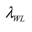
In a first step, the ionosphere-free geometry-free Melbourne- Wϋbbena (MW) combination [1] is computed:

where the receiver and time indices have been omitted and denotes the wavelength of
 the widelane combination.
In a second step, the Ll/ L2 ionosphere-free (IF) carrier phase combination is determined, i.e.

which includes the joint ambiguity/ bias term that is defined as


Finally, the MW and IF ambiguity/ bias terms are combined by


The bias estimate on L2 is obtained in a similar way by combining this bias and the MW bias, i.e.

These biases are provided by the reference station 15 and enable the mobile navigation device 5 to determine unbiased Ll and L2 integer ambiguities.
However, there exist some critical aspects of this approach: First, the Ll and L2 phase biases can not be determined separately as (39) and (40) also include Ll and L2 code biases. Secondly, the geometry-preserving, ionosphere-free linear combination to which the bias estimates correspond is a narrowlane combination with a wavelength of only 10.7 cm. Any linear combination of the bias estimates in (39) and (40) does not refer to a geometry-preserving, ionosphere-free linear combination with a larger wavelength than 10.7 cm. Another critical point is the significant code noise in the narrowlane combination. All these aspects are the foundation for the design of new ionosphere-free mixed code- carrier combinations for bias estimation.
3.2 Bias estimation with mixed code-carrier combinations
The following scheme is suggested for bias estimation:
In a first step, satellite-satellite single difference measurements of code and phase singals are computed where the satellite 2 of highest elevation is typically chosen as a reference satellite.
In a second step, a geometry-preserving, ionosphere-free combination with maximum combination discrimination is then computed from the single difference measurements.
Alternatively, the geometry-preserving, ionosphere-free combination is computed in the first step and single differences are performed in a second step.
For the linear combination, a linear combination of Table 5 is advantageously be used due to its robustness with respect to both stochastical errors and biases. The bias robustness has been introduced as there exist biases like multipath that depend on the location of the mobile navigation device and can not be estimated at the reference station 15. If the maximum bias shall be bounded to a perde fined value, a linear combination of Table 4 is advantageously used. If residual biases due to multipath are negligible, a linear combination of either Table 2 or 3 can be chosen. In the following simulations, the first combination of Table 2 has been chosen.
The single differences of this mixed code-carrier combination are written in matrix-vector notation as

where NT denotes the number of measurement times and K designates the reference satellite 2.
In a third step, the single difference ranges and the single difference satellite clock offsets are computed from the known ephemeris and the known position of the reference station 15. The sum of the single difference ranges and the single difference satellite clock offsets is denoted as Ar and subtracted from the single difference measurements. The obtained linear combinations are modeled as
with
and

where mw denotes a mapping function for the tropospheric wet zenith delay. Typically, the
Niell mapping function of [10] is chosen due to its independence from meteorological data. Then, a weighted least-square estimation of SD combination biases Δb and of the tropospheric wet zenith delay is performed. As the integer valued ambiguities and real-
 valued biases can not be estimated individually, a common ambiguity/bias term ΔN + Δb is estimated and then split into an integer part ΔN and a fractional part Δb . The fractional part Δb is then broadcasted as a correction term. Any mobile navigation device 5 can then use this bias for precise point positioning with the linear combinations.
In the following simulations, 1 Hz measurements are considered over 10 minutes. The covariance matrix of SDs with a common reference satellite 2 is characterized by for
 the diagonal elements and by σ for the off-diagonal elements.

Figure 3 shows that a standard deviation between a few millimetres and 2.5 cm is achievable for the SD bias estimates of the ionosphere-free mixed code-carrier combination with

The accuracy of bias estimation can be significantly improved by using an additional LIE5 ionosphere-free code-carrier combination. Time-differenced satellite-satellite single difference measurements are used for this combination to avoid the introduction of
additional biases and ambiguities. The weighting coefficients are uniquely described by four constraints: Preservation of geometry, elimination of ionosphere, uncorrelated to first combination (of maximum discrimination) and minimum noise amplification. The Ll/ E5 phase weights are obtained as
 and the respective code coefficients are β2 = 0.0002 , β2 = 0.1294 . The noise level of this linear combination is characterized by a standard deviation of only 2.3 mm. Both linear combinations are written in matrix-vector notation as
with

Figure 4 demonstrates the benefit of this second combination of time-differenced measurements for bias estimation. The uncertainty of critical SD bias estimates from the first code-carrier combination can be reduced by at least one order of magnitude. Each point refers to one SD for one epoch and the different colors represent different batch intervals.
The benefit of the second linear combination of time-differenced measurements motivates the reduction of the measurement batch interval to 5 min. Figure 5 demonstrates an achievable SD bias accuracy between 3 mm and 11 mm whereas the higher values refer to low elevation satellites. The respective SD biases can be estimated more accurately by another reference station with better visibility.
3.3 PPP with mixed code-carrier combinations
PPP is performed with mixed code-carrier phase combinations using the bias estimates from the reference station 15. The SD mixed code-carrier phase measurements are modeled at the mobile navigation device 5 similar to (45) as

with the geometry matrix , the user position x and the SD direction
 vectors
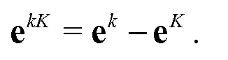
The least-square estimation of x , ΔN and is supported by a second L1-E5 code-only
 combination of minimum noise amplification. This geometry-preserving, ionosphere-free combination (βι = 2.338, β2 = -1.338 ) has a noise level of O
 and is uncorrelated with the mixed code-carrier combination ( λ = 3.215m ). In the further analysis, the single difference operator Δ is omitted to simplify notation.
The integer ambiguity resolution is based on sequential bootstrapping [11] which achieves a higher success rate than direct rounding. The traditional bootstrapping fixes the ambiguities in the following order: First, the integer ambiguity of the lowest variance is fixed. Then, this ambiguity is removed from the measurements, a new real-valued "float solution" of the position of the mobile navigation device 5, ambiguities and tropospheric zenith delay are computed, and the most reliable float ambiguity is fixed. This step is repeated until all ambiguities are fixed. The sequential fixing takes the correlation between float ambiguity estimates into account and achieves a lower probability of wrong fixing than traditional rounding. Teunissen has expressed the integer ambiguity estimates in [6] as a function of the conditional variances, i.e.
and
 with [•] denoting the rounding to the nearest integer and
 The sequential ambiguity estimator can also be written in matrix-vector notation as
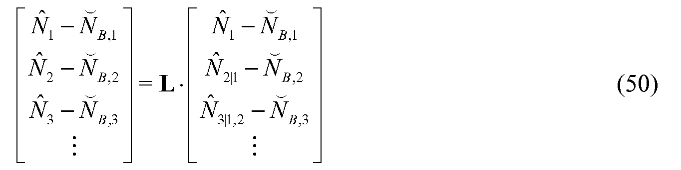
with The conditional
 variances of are obtained from a triangular decomposition of the float ambiguity covariance matrix Σ . The success rate of the bootstrapped
 estimator depends on the order of ambiguity fixings and is given in [12] as
with the conditional biases

The sequential fixing can be applied to the float ambiguities in original order or to a permutation of the float ambiguities, e.g. sorted w.r.t. the variances. The success rate of the bootstrapped estimator is significantly increased if an integer decorrelation transformation Z [12] is applied to the float ambiguities before sequential fixing.
Figure 6 shows the probability of wrong fixing of SD ambiguities for different bootstrapping estimators and known biases. The integer decorrelation transformation reduces the error rate by up to ten orders of magnitude for some epochs. The high reliability of single epoch ambiguity fixing is caused by the large wavelength of λ = 3.215m and the low code noise level of the mixed code-carrier combination.
The conditional float ambiguity biases are related to the residual biases of the mixed
 code-carrier combination (I)1) and of the code-only combination (b2) by
with

An upper bound for the k -th conditional ambiguity bias is given for


Figure 7 shows the impact of (uncorrected) residual SD biases on the probability of wrong fixing. A residual bias of 2 cm for the mixed code-carrier combination and of 10 cm for the code -only combination reduces the success rate only slightly due to the large wavelength of the linear combination.
The success rate of instantaneous ambiguity resolution can be significantly increased by using measurements from multiple epochs. Position and tropospheric wet zenith delay are estimated once per epoch for PPP.
Figure 8 shows that the probability of wrong fixing can be reduced to less than 10 10 within 5 s. Consequently, CAT III requirements for aircraft landing can be fulfilled for ambiguity resolution of the mixed code-carrier combination.
After ambiguity fixing, the mixed-code carrier and code-only combinations of SD measurements are corrected by ambiguities/ biases and the receiver position is estimated, i.e.

with the selection matrix
 The positioning accuracy is improved if the ionosphere-free carrier smoothing of [13] is applied to the mixed code-carrier combination. The smoothed linear combination is written as

with
 . This geometry- free, ionosphere-free term is filtered by a low pass filter, i.e.

The smoothing combination Acφc is geometry-preserving, ionosphere-free and of minimum noise. The variance of the smoothed mixed code-carrier combination is given by [5] as


Figure 9 shows the single epoch positioning accuracy with SD measurements by 120s ionosphere-free carrier smoothing of the ionosphere-free code-carrier combination with λ = 3.215m , aided by a code-only combination. Figure 9 further shows a standard deviation of a few millimetres for the horizontal position and of less than 5 cm for the vertical position in 90 % of the epochs. A high correlation between the vertical position error and tropospheric zenith delay is observed and degrades the vertical positioning accuracy to a few decimetres for a few epochs.
The bias estimation at the reference station leaves some residual biases whose impact on the position is shown in Figure 10. The mixed-code carrier SD residual biases have been chosen according to the standard deviations of Figure 3. The residual biases of the code- only SD combination are assumed to be 10 times larger. The vertical position bias is highly correlated with the tropospheric zenith delay bias and varies between 1 cm and 10 cm.
A comparison of Figure 9 and 10 shows that standard deviation and bias of the receiver position are characterized by a similar order of magnitude although the biases are slightly more critical. The lower standard deviation is achieved by the ionosphere-free carrier smoothing which does not affect the biases of the mixed code-carrier combination.
4. PPP with satellite-satellite SD measurements without linear combinations
The estimation of SD phase and code biases on each frequency is not feasible as at least one bias can not be distinguished from the ionospheric delay. However, the Galileo E5a and E5b signals are modulated onto the same carrier which motivates the assumption of a
common bias. In this case, the Ll and E5 SD code and phase biases can be determined separately. The accuracy can be increased if the E5c signal which corresponds to the central lobe between E5a and E5b is also taken into account.
First, the widelane ambiguities between E5a and E5b (λ = 9.76m ) as well as between E5a and E5c {λ = 19.52m ) are determined with the Melbourne- Wubbena combination [I]. Thus, the three E5 ambiguities and phase biases are reduced to a single ambiguity and a single phase bias. The SD code and phase measurements on all four frequencies are modeled for a reference station 15 of known position as
with


Both ionospheric and tropospheric delays are assumed piecewise linear. The design matrices for ionospheric/ tropospheric gradients are given by

where r7 and rτ denote the rate of ionospheric/ tropospheric gradient estimation and
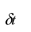 represents the time interval between two measurements. Both ionosphere and troposphere
are nuisance parameters for bias estimation and are eliminated by an orthogonal projection [14]. The phase bias estimates are obtained as
represents the time interval between two measurements. Both ionosphere and troposphere
are nuisance parameters for bias estimation and are eliminated by an orthogonal projection [14]. The phase bias estimates are obtained as
with

and the orthogonal projection

Moreover, the complexity can be further reduced if the sparse properties of A1 , ... , A6 and the block diagonal structure of the covariance matrix Σ are taken into account.
Figure 11 shows the achievable accuracy for SD phase bias estimation with uncombined phase and code measurements at a single reference station. Simulated 1 Hz measurements on Ll, E5a, E5b and E5c have been generated for periods of 10 min. A phase noise of
 mm has been assumed and the code noise has been chosen according to the CRB for 45 dBHz, i.e. for El (MB0C(6,l,l/l l), 20 MHz), σp ^ = 8.29 cm
 for E5a/b (BPSK(IO), 20 MHz) and σ ^ = 15.10 cm for E5c (AItBOC(15, 10), 10 MHz).
The ionospheric gradients are estimated once per 10 s and the gradient of the tropospheric wet zenith delay is updated every 120 s.
The standard deviation of the SD Ll phase bias estimates varies between 2 mm and 7 mm with the exception of two epochs where one SD shows a standard deviation of 2 cm. This outlier is explained by the low elevation angle (5°) of the respective satellite and the low number of visible satellites. This SD phase bias can be determined more accurately at a different reference station.
The standard deviation of SD phase bias estimates in Figure 11 is one to two orders of magnitude lower than the weighted code bias (b = 10cm ) in the Ll phase bias estimate of (38). The uncombined phase biases might also be beneficial for single frequency receivers which can not form the MW combination.
5 Advantages
Precise point positioning with satellite-satellite single difference measurements requires precise estimates of the phase and code biases for ambiguity resolution.
A method for satellite-satellite single difference bias estimation has been described for precise point positioning. It uses an ionosphere-free mixed code-carrier combination of maximum ambiguity discrimination defined as ratio between wavelength and noise standard deviation. The L1-E5 linear combination of maximum discrimination is characterized by a wavelength of 3.215 m, a low noise level of 3.76 cm, and an El code multipath suppression by 23.5 dB. The wavelength of 3.215 m of the L1-E5 linear combination of maximum discrimination is four time larger than the wavelength of the LIES Melbourne- Wϋbbena combination. In contrast to the Melbourne -Wϋbbena combination, the proposed mixed code-carrier combination is a geometry-preserving linear combination so that the bias estimates are directly applicable at the mobile receiver 5. The single difference biases of the discrimination maximizing linear combination are determined at a single reference station 15 with an accuracy between a few millimeters and 1 cm within 5 min. As these biases refer to a geometry-preserving linear combination, they are directly applicable at the mobile navigation device 5.
The accuracy of bias estimation is further improved by an additional ionosphere-free LIES mixed code-carrier combination of time-differenced measurements that is uncorrelated with the discrimination maximizing combination. The additional combination uses time- differenced measurements to avoid the introduction of additional ambiguities and biases.
Moreover, the SD phase and code biases on Ll and E5 can also be determined separately by subdividing the Galileo E5 band into the E5a, E5b and E5c band whereas the latter one corresponds to the central lobe between E5a and E5b.
The methods descibed above can also be implemented in software poducts that contain program code for performing the methods. The software product can in particular be stored on a computer readable storage medium or data carrier that can also be an electrical signal of a data network.
Generally, it should be noted that linear operations on phase or code signals can be perfomed in any order. For instance, the subtraction 20 of the know ranges and clock offesets in Figure 2 can also be perfomed before the computation 19 of satellite-satellite single differences. In a corresponding way, the sequence of any other linear operations can be inverted.
It should further be noted that, throughout the description and claims of this specification, the singular encompasses the plural unless the context otherwise requires. In particular, where the indefinite article is used, the specification is to be understood as contemplating plurality as well as singularity, unless the context requires otherwise.
Features, integers, characteristics, compounds or groups described in conjunction with a particular aspect, embodiment or example of the invention are further to be understood to be applicable to any other aspect, embodiment or example described herein unless incompatible therewith.
 Table 3 : GP-IF-NP mixed code-carrier widelane and narrowlane combinations of maximum ambiguity discrimination for


Table 4: GP-IF-NP mixed code-carrier wide lane combinations of maximum ambiguity discrimination for mm , with constraint worst-case combination


 biases for b cm and cm on all frequencies


Table 5: GP-IF-NP mixed code-carrier widelane combinations of maximum λ discrimination
 all frequencies

References
[1] G. Wϋbbena, Software developments for geodetic positioning with GPS using TI-4100 code and carrier measurements, Proc. of 1-st Intern. Symposium on Precise Positioning with the Global Positioning System, Rockville, USA, pp. 403-412, Apr. 1985.
[2] M. Gabor and S. Nerem, Satellite-satellite single difference phase calibration as applied to ambiguity resolution, Navigation, Vol. 49, Nr. 4, pp. 223-242, 2002.
[3] M. Ge, G. Gendt, M. Rothacher, C. Shi and J. Liu, Resolution of GPS carrier-phase ambiguities in Precise Point Positioning (PPP) with daily observations, Journal of Geodesy, Springer, Oct. 2007.
[4] D. Laurichesse and F. Mercier, Integer ambiguity resolution on undifferenced GPS phase measurements and its application to PPP, Proc. of ION-GNSS, Forth Worth, USA, Sep. 2007.
[5] P. Henkel and C. Gϋnther, Joint L/C-Band Code-Carrier Linear Combinations for Galileo, International Journal of Navigation and Observation, Special Issue on Future GNSS Signals, Hindawi Publ, Jan. 2008.
[6] P. Teunissen, An optimal property of the integer least-square estimator, Journal of Geodesy, Vol. 73, Nr. 11, pp. 587-593, Springer, JuI. 1999.
[7] G. Hein, J. Godet, J.-L. Issler, J. Martin, P. Erhard, R. Lucas-Rodriguez and T. Pratt, Status of Galileo frequency and signal design, Proc. of ION-GPS, Portland, USA, 2002.
[8] G. Hein, J. Avila-Rodriguez, S. Wallner, A. Pratt, J. Owen, J.-L. Issler. J. Betz, C. Hegarty, S. Lenahan, J. Rushanan, A. Kraay and T. Stansell, MBOC: The New Optimized Spreading Modulation Recommended for GALILEO Ll OS and GPS LlC, Proc. of the IEEE/ION PLANS, San Diego, pp. 883-892, Apr. 2006.
[9] Galileo Open Service Signal-in-Space ICD, available online: http:// www.galileoju.com, Mai 2006.
[10] A. Niell, Global Mapping Functions for the Atmosphere Delay at Radio Wavelengths, Journal of Geophysical Research, Vol. 101, pp. 3227-3246, 1996.
[11] G. Blewitt, Carrier-phase ambiguity resolution for the Global Positioning System applied to geodetic baselines up to 2000 km, Journal Geophysic Research, Vol. 94, pp. 10187-10203, 1989.
[12] P. Teunissen, Integer estimation in the presence of biases, Journal of Geodesy, Vol. 75, Nr. 11, pp. 399-407, Springer, Mar. 2001.
[13] R. Hatch, A new three frequency, geometry-free technique for ambiguity resolution, Proc. of ION-GNSS, Fort Worth, USA, pp. 309-316, 2006.
[14] P. Teunissen, Adjustment Theory: Partitioned model representations, Series on Mathematical Geodesy and Positioning, Delft University Press, 2000.
[15] J. Betz, Binary Offset Carrier Modulations for Radionavigation, Navigation, Vol. 48, No. 4, pp. 227-246, 2002.
Claims
1. A method for a global satellite navigation system with at least two carriers (4), from which a linear combination is formed combined by a reference station (15) for estimating a satellite-satellite single difference phase and code bias, wherein the estimated bias is provided to a mobile receiver (5), enabling the mobile receiver to compute the same linear combination, subtracts the bias from the linear combination and determines integer phase ambiguities, c h a r a c t e r i z e d i n t h a t the satellite-satellite single difference bias of a single ionosphere-free, geometry-preserving combination of the code and phase signals of at least two carriers (4) is determined by using a maximum combination discrimination requirement or a minimum noise requirement for the linear combination.
2. The method according to Claim 1, wherein an ionosphere-free mixed code-carrier bias, integer phase ambiguities and tropospheric wet zenith delays are obtained by the reference station (15) using a least- square estimation.
3. The method according to Claim 1 or 2, wherein the combination discrimination requirement is defined as the ratio of the wavelength of the combination and the weighted sum formed by the bias of the combination and by the standard deviation of the combination.
4. The method according to Claim 3, wherein the combination discrimination requirement is defined as the ratio of the wavelength of the combination and standard deviation of the mixed code-carrier combination noise.
5. The method according to any one of Claims 1 to 4, wherein the reference station (15) is transmitting the bias together with the standard deviation associated with the bias.
6. The method according to any one of Claims 1 to 5, wherein an additional geometry-preserving, ionosphere-free combination of time differences of measurements or time differences of geometry-preserving, ionosphere-free combinations of measurements are used for determining the biases, wherein the weighting coefficients of the additional combination fulfill the requirement that the additional combination and the combination according to any one of Claim 1 to 5 are uncorrelated.
7. A method for a global satellite navigation system with a plurality of carriers used by a reference station (15) for estimating a satellite-satellite single difference phase and code bias, wherein the estimated bias is provided to a mobile receiver (5), enabling the mobile receiver (5) to use the bias for determining integer phase ambiguities, c h a r a c t e r i z e d i n t h a t individual biases are determined for the phase signal and the code signal of at least three carriers (4), wherein at least two carriers (4) belong to a common frequency band and have the same bias, and that the biases are transmitted to the mobile receiver (5) which uses the biases for determining integer phase ambiguities.
8. The method according to Claim 7, wherein the individual biases of the Ll phase signal, the E5 phase signal, the Ll code signal and the E5 code signal are determined by dividing the Galileo E5 band into at least two subbands.
9. The method according to Claim 8, wherein the Galileo E5 band is split into the subbands E5a, E5b and E5c, the latter one corresponding to the central lobe between E5a and E5b.
10. The method according to any one of Claims 7 to 9, wherein an orthogonal projection is used for the bias estimation to eliminate both iono- spheric and tropospheric errors.
11. The method according to any one of Claims 7 to 10, wherein the reference station (15) is transmitting the biases together with the standard deviations associated with the biases.
12. A method for a global satellite navigation system with a plurality of carriers (4) used by a reference station (15) for estimating a satellite-satellite single difference phase and code bias, wherein the estimated bias is provided to a mobile receiver (5), enabling the mobile receiver (5) to use the bias for determining a integer phase ambiguity, c h a r a c t e r i z e d i n t h a t the methods according to any one of Claims 1 to 6 and the method according to any one of Claims 6 to 11 are both performed and that the bias resulting from the method according to any one of Claims 1 to 6 is used by the reference station (15) for verifying the individual biases resulting from the method according to any one of Claims 7 to 11.
13. The method according to Claim 12, wherein the bias resulting from the method according to any one of Claims 1 to 6 is used if the individual biases resulting from the method according to any one of Claims 7 to 11 are stated invalid.
14. A reference station for a global satellite navigation system adapted for estimating phase and code bias c h a r a c t e r i z e d i n t h a t the reference station (15) is arranged for executing a method according to any one of the
Claims 1 to 13.
15. A method for a global satellite navigation system with a plurality of carriers, in which a mobile navigation device (5) receives a bias from a reference station (15) and uses the bias for determining integer phase ambiguities, c h a r a c t e r i z e d i n t h a t the mobile navigation device (5) uses the same linear combination as used by the refer- enced station (15) while executing a method according to anyone of the Claims 1 to 6, and that mobile navigation device (5) subtract the biases received by the reference station (15) from the linear combination and determines phase ambiguities.
16. A mobile navigation device for a global satellite navigation adapted for using phase and code bias c h a r a c t e r i z e d i n t h a t the device is arranged for executing a method according to Claims 15.
17. A software product for navigation purposes, c h a r a c t e r i z e d i n t h a t the software product comprises program code for implementing any one of the methods according to claim 1 to 13 and 15.
Priority Applications (3)
| Application Number | Priority Date | Filing Date | Title |
|---|---|---|---|
| ES09734936T ES2413064T3 (en) | 2008-04-22 | 2009-04-22 | Procedure for a global satellite navigation system |
| EP09734936A EP2281210B1 (en) | 2008-04-22 | 2009-04-22 | Method for a global satellite navigation system |
| US12/910,433 US8188913B2 (en) | 2008-04-22 | 2010-10-22 | Method for a global satellite navigation system |
Applications Claiming Priority (2)
| Application Number | Priority Date | Filing Date | Title |
|---|---|---|---|
| EP08007781.1 | 2008-04-22 | ||
| EP08007781 | 2008-04-22 |
Related Child Applications (1)
| Application Number | Title | Priority Date | Filing Date |
|---|---|---|---|
| US12/910,433 Continuation US8188913B2 (en) | 2008-04-22 | 2010-10-22 | Method for a global satellite navigation system |
Publications (2)
| Publication Number | Publication Date |
|---|---|
| WO2009130260A2 true WO2009130260A2 (en) | 2009-10-29 |
| WO2009130260A3 WO2009130260A3 (en) | 2010-02-11 |
Family
ID=40852440
Family Applications (1)
| Application Number | Title | Priority Date | Filing Date |
|---|---|---|---|
| PCT/EP2009/054855 Ceased WO2009130260A2 (en) | 2008-04-22 | 2009-04-22 | Method for a global satellite navigation system |
Country Status (4)
| Country | Link |
|---|---|
| US (1) | US8188913B2 (en) |
| EP (1) | EP2281210B1 (en) |
| ES (1) | ES2413064T3 (en) |
| WO (1) | WO2009130260A2 (en) |
Cited By (3)
| Publication number | Priority date | Publication date | Assignee | Title |
|---|---|---|---|---|
| US11525924B2 (en) | 2018-10-05 | 2022-12-13 | Dlr Gfr Mbh | Method for providing authenticated correction information, plurality of reference stations and a redundant central computation unit, GNS system and software product and/or network for providing a correction information message in a GNS system or other means |
| CN116113854A (en) * | 2020-08-20 | 2023-05-12 | 高通股份有限公司 | DGNSS/RTK base station position deviation detection and calculation |
| DE112010003681B4 (en) | 2009-09-19 | 2024-06-13 | Trimble Navigation Limited | GNSS signal processing for estimating MW biases |
Families Citing this family (18)
| Publication number | Priority date | Publication date | Assignee | Title |
|---|---|---|---|---|
| US20120016574A1 (en) * | 2010-07-16 | 2012-01-19 | Research In Motion Limited | Gps trace filtering |
| US8655282B2 (en) * | 2010-10-29 | 2014-02-18 | Qualcomm Incorporated | Multiple signal transformation in wireless receivers |
| DE102012202095A1 (en) * | 2011-02-14 | 2012-08-16 | Trimble Navigation Ltd. | Method for processing set of global navigation satellite system signal data for e.g. global positioning system, involves using network ambiguities and ionospheric delays to estimate ionospheric phase bias per satellite |
| US9198150B2 (en) | 2013-03-07 | 2015-11-24 | Raytheon Company | Link path delay estimator that combines coarse and fine delay estimates |
| US9071234B2 (en) | 2013-03-07 | 2015-06-30 | Raytheon Company | High-resolution link-path delay estimator and method for estimating a signal-path delay |
| US20150291294A1 (en) | 2014-04-11 | 2015-10-15 | Sean B. Warner | System, Apparatus, and Method of Efficiently Transferring Material from a Container to a Cartridge |
| US10379225B2 (en) * | 2016-03-18 | 2019-08-13 | Deere & Company | Satellite navigation receiver with improved ambiguity resolution |
| US10802160B2 (en) * | 2016-03-18 | 2020-10-13 | Deere & Company | Rapid determination of precise position by aiding data |
| US10012738B2 (en) * | 2016-03-24 | 2018-07-03 | Hitachi Zosen Corporation | Positioning method and positioning apparatus using satellite positioning system |
| JP6593879B2 (en) * | 2016-03-24 | 2019-10-23 | 日本電気株式会社 | Satellite positioning system, positioning terminal, positioning method, and program |
| US10495727B2 (en) | 2017-02-07 | 2019-12-03 | Raytheon Company | Phase difference estimator and method for estimating a phase difference between signals |
| US10884133B2 (en) * | 2017-03-30 | 2021-01-05 | Mitsubishi Electric Research Laboratories, Inc. | Positioning system for global navigational satellite system |
| US10338233B2 (en) * | 2017-04-12 | 2019-07-02 | Coherent Technical Services, Inc. | Assured validation of carrier-phase integer ambiguities for safety-of-life applications |
| EP3828595A1 (en) | 2019-11-28 | 2021-06-02 | Spaceopal GmbH | Method for providing differential code bias (dcb) correction for a global navigation satellite system (gnss) |
| CN111045034B (en) * | 2019-12-13 | 2020-09-29 | 北京航空航天大学 | GNSS multi-system real-time precise time transfer method and system based on broadcast ephemeris |
| EP3933444A1 (en) | 2020-06-30 | 2022-01-05 | Spaceopal GmbH | Method for determining a state parameter of a receiver and an apparatus for performing such a method |
| EP4099061A1 (en) | 2021-05-31 | 2022-12-07 | Spaceopal GmbH | Method for generating and providing a precise positioning solution of a mobile receiver in a gnss system by a central computation unit and a software product and its dissemination |
| CN114527491B (en) * | 2022-01-05 | 2023-06-30 | 浙江时空道宇科技有限公司 | Method, device, equipment and storage medium for monitoring code deviation data of navigation system |
Family Cites Families (11)
| Publication number | Priority date | Publication date | Assignee | Title |
|---|---|---|---|---|
| US4812991A (en) * | 1986-05-01 | 1989-03-14 | Magnavox Govt. And Industrial Electronics Company | Method for precision dynamic differential positioning |
| US5148179A (en) * | 1991-06-27 | 1992-09-15 | Trimble Navigation | Differential position determination using satellites |
| US5359332A (en) * | 1992-12-31 | 1994-10-25 | Trimble Navigation Limited | Determination of phase ambiguities in satellite ranges |
| US6061631A (en) * | 1997-07-03 | 2000-05-09 | Trimble Navigation, Ltd. | Hybrid approach for antenna baseline self-survey and line bias calibration using GPS carrier phase |
| US6166683A (en) * | 1998-02-19 | 2000-12-26 | Rockwell International Corporation | System and method for high-integrity detection and correction of cycle slip in a carrier phase-related system |
| US6219376B1 (en) * | 1998-02-21 | 2001-04-17 | Topcon Positioning Systems, Inc. | Apparatuses and methods of suppressing a narrow-band interference with a compensator and adjustment loops |
| US6163754A (en) * | 1998-11-25 | 2000-12-19 | Trimble Navigation Limited | Compensation for line bias variation |
| JP3727219B2 (en) * | 2000-03-31 | 2005-12-14 | 日立造船株式会社 | Displacement measurement method using GPS |
| US7002513B2 (en) * | 2004-03-26 | 2006-02-21 | Topcon Gps, Llc | Estimation and resolution of carrier wave ambiguities in a position navigation system |
| EP1724605A1 (en) * | 2005-05-18 | 2006-11-22 | Leica Geosystems AG | Method of determining position for a satellite based positioning system |
| US7439908B1 (en) * | 2006-05-05 | 2008-10-21 | Topcon Gps, Llc | Method and apparatus for determining smoothed code coordinates of a mobile rover |
-
2009
- 2009-04-22 ES ES09734936T patent/ES2413064T3/en active Active
- 2009-04-22 WO PCT/EP2009/054855 patent/WO2009130260A2/en not_active Ceased
- 2009-04-22 EP EP09734936A patent/EP2281210B1/en not_active Not-in-force
-
2010
- 2010-10-22 US US12/910,433 patent/US8188913B2/en active Active
Non-Patent Citations (4)
| Title |
|---|
| BANVILLE, S. ET AL.: "Satellite and Receiver Phase Bias Calibration for Undifferenced Ambiguity Resolution", PROC. OF THE 2008 NATIONAL TECHNICAL MEETING OF THE ION, 28 January 2008 (2008-01-28), pages 711 - 719 |
| GABOR, M. J. ET AL.: "GPS Carrier Phase Ambiguity Resolution Using Satellite - Satellite Single Differences", PROCEEDINGS OF THE INSTITUTE OF NAVIGATION (ION) GPS, 17 September 1999 (1999-09-17), pages 1569 - 1578 |
| GABOR, M.; NEREM, S.: "Satellite-satellite single difference phase calibration as applied to ambiguity resolution", NAVIGATION, vol. 49, no. 4, 2002, pages 223 - 242, XP007913621 |
| HENKEL, P. ET AL.: "Three frequency linear combinations for Galileo", POSITIONING, NAVIGATION AND COMMUNICATION, 2007, 1 March 2007 (2007-03-01), pages 239 - 245, XP031080644 |
Cited By (3)
| Publication number | Priority date | Publication date | Assignee | Title |
|---|---|---|---|---|
| DE112010003681B4 (en) | 2009-09-19 | 2024-06-13 | Trimble Navigation Limited | GNSS signal processing for estimating MW biases |
| US11525924B2 (en) | 2018-10-05 | 2022-12-13 | Dlr Gfr Mbh | Method for providing authenticated correction information, plurality of reference stations and a redundant central computation unit, GNS system and software product and/or network for providing a correction information message in a GNS system or other means |
| CN116113854A (en) * | 2020-08-20 | 2023-05-12 | 高通股份有限公司 | DGNSS/RTK base station position deviation detection and calculation |
Also Published As
| Publication number | Publication date |
|---|---|
| EP2281210B1 (en) | 2013-03-20 |
| US8188913B2 (en) | 2012-05-29 |
| US20110122020A1 (en) | 2011-05-26 |
| ES2413064T3 (en) | 2013-07-15 |
| EP2281210A2 (en) | 2011-02-09 |
| WO2009130260A3 (en) | 2010-02-11 |
Similar Documents
| Publication | Publication Date | Title |
|---|---|---|
| EP2281210B1 (en) | Method for a global satellite navigation system | |
| US8089397B2 (en) | Method for processing radionavigation signals | |
| US7982667B2 (en) | Post-processed accuracy prediction for GNSS positioning | |
| EP2575271B1 (en) | Position Estimation Using a Network of Global-Positioning Receivers | |
| CN103221839B (en) | GNSS signal processing with regional augmentation message | |
| US8717237B2 (en) | GNSS signal processing methods and apparatus | |
| CA2550600C (en) | A method for combined use of a local rtk system and a regional, wide-area, or global carrier-phase positioning system | |
| US10082578B2 (en) | PPP-RTK method and system for GNSS signal based position determination | |
| EP2663878B1 (en) | Navigation system and method for resolving integer ambiguities using double difference ambiguity constraints | |
| US8134497B2 (en) | Method and system for location-dependent time-specific correction data | |
| US8035552B2 (en) | Distance dependant error mitigation in real-time kinematic (RTK) positioning | |
| US9958550B2 (en) | Navigation satellite system positioning involving the generation of receiver-specific or receiver-type-specific correction information | |
| EP3109672B1 (en) | Gnss receiver with a capability to resolve ambiguities using an uncombined formulation | |
| CN101680943A (en) | Range-dependent error mitigation in real-time kinematic (RTK) positioning | |
| WO2005043186A2 (en) | Method for generating clock corrections for a wide-area or global differential gps system | |
| CN109212562A (en) | A method of generating carrier wave pseudo range observed quantity | |
| Liu et al. | The benefit of Galileo E6 signals and their application in the real-time instantaneous decimeter-level precise point positioning with ambiguity resolution | |
| US8624777B2 (en) | Method for determining the distance between a transmitter and a receiver | |
| Dai et al. | Real-time uncombined PPP using BDS-3 PPP-B2b products with different multi-frequency integrations and refined stochastic model | |
| Henkel et al. | Precise point positioning with multiple Galileo frequencies | |
| Tschofen | Evaluation of Commercial Off-the-Shelf GNSS Receivers for Nanosatellite Applications | |
| Douša | Processing of ground-based GNSS data to produce near real time (NRT) tropospheric zenith path delays (ZTD) |
Legal Events
| Date | Code | Title | Description |
|---|---|---|---|
| 121 | Ep: the epo has been informed by wipo that ep was designated in this application |
Ref document number: 09734936 Country of ref document: EP Kind code of ref document: A2 |
|
| NENP | Non-entry into the national phase |
Ref country code: DE |
|
| WWE | Wipo information: entry into national phase |
Ref document number: 2009734936 Country of ref document: EP |