WO2009130954A1 - 送風機およびこの送風機を用いたヒートポンプ装置 - Google Patents
送風機およびこの送風機を用いたヒートポンプ装置 Download PDFInfo
- Publication number
- WO2009130954A1 WO2009130954A1 PCT/JP2009/054645 JP2009054645W WO2009130954A1 WO 2009130954 A1 WO2009130954 A1 WO 2009130954A1 JP 2009054645 W JP2009054645 W JP 2009054645W WO 2009130954 A1 WO2009130954 A1 WO 2009130954A1
- Authority
- WO
- WIPO (PCT)
- Prior art keywords
- upstream
- blower
- enlarged portion
- outer peripheral
- peripheral edge
- Prior art date
- Legal status (The legal status is an assumption and is not a legal conclusion. Google has not performed a legal analysis and makes no representation as to the accuracy of the status listed.)
- Ceased
Links
Images


Classifications
-
- F—MECHANICAL ENGINEERING; LIGHTING; HEATING; WEAPONS; BLASTING
- F24—HEATING; RANGES; VENTILATING
- F24F—AIR-CONDITIONING; AIR-HUMIDIFICATION; VENTILATION; USE OF AIR CURRENTS FOR SCREENING
- F24F1/00—Room units for air-conditioning, e.g. separate or self-contained units or units receiving primary air from a central station
- F24F1/06—Separate outdoor units, e.g. outdoor unit to be linked to a separate room comprising a compressor and a heat exchanger
- F24F1/38—Fan details of outdoor units, e.g. bell-mouth shaped inlets or fan mountings
-
- F—MECHANICAL ENGINEERING; LIGHTING; HEATING; WEAPONS; BLASTING
- F04—POSITIVE - DISPLACEMENT MACHINES FOR LIQUIDS; PUMPS FOR LIQUIDS OR ELASTIC FLUIDS
- F04D—NON-POSITIVE-DISPLACEMENT PUMPS
- F04D29/00—Details, component parts, or accessories
- F04D29/08—Sealings
- F04D29/16—Sealings between pressure and suction sides
- F04D29/161—Sealings between pressure and suction sides especially adapted for elastic fluid pumps
- F04D29/164—Sealings between pressure and suction sides especially adapted for elastic fluid pumps of an axial flow wheel
-
- F—MECHANICAL ENGINEERING; LIGHTING; HEATING; WEAPONS; BLASTING
- F04—POSITIVE - DISPLACEMENT MACHINES FOR LIQUIDS; PUMPS FOR LIQUIDS OR ELASTIC FLUIDS
- F04D—NON-POSITIVE-DISPLACEMENT PUMPS
- F04D29/00—Details, component parts, or accessories
- F04D29/40—Casings; Connections of working fluid
- F04D29/52—Casings; Connections of working fluid for axial pumps
- F04D29/522—Casings; Connections of working fluid for axial pumps especially adapted for elastic fluid pumps
- F04D29/526—Details of the casing section radially opposing blade tips
-
- F—MECHANICAL ENGINEERING; LIGHTING; HEATING; WEAPONS; BLASTING
- F24—HEATING; RANGES; VENTILATING
- F24F—AIR-CONDITIONING; AIR-HUMIDIFICATION; VENTILATION; USE OF AIR CURRENTS FOR SCREENING
- F24F1/00—Room units for air-conditioning, e.g. separate or self-contained units or units receiving primary air from a central station
- F24F1/06—Separate outdoor units, e.g. outdoor unit to be linked to a separate room comprising a compressor and a heat exchanger
- F24F1/40—Vibration or noise prevention at outdoor units
Definitions
- the present invention relates to a propeller fan type blower including a bell mouth and an impeller, and a heat pump device using the blower, and more particularly to an improvement in the structure of the bell mouth.
- suction side wall portion of the bell mouth have a cross-sectional shape that curves in a substantially semicircular shape radially outward from the inner peripheral surface of the suction port, air separation at the suction port portion is suppressed.
- a fan that reduces fan operation noise has been proposed (see, for example, Patent Document 2).
- the shape of the bell mouth is determined according to the distance between the upper and lower peripheral side plates of the outdoor unit box surrounding the periphery and the outer periphery of the impeller.
- Japanese Patent Laid-Open No. 2003-184797 (FIGS. 1 to 3) Japanese Patent No. 3084790 (FIGS. 1 and 2) Japanese Patent No. 2769211 (FIGS. 2 and 3)
- a cross section in which a straight portion extending radially outward is provided at the mouth edge portion of the bell mouth or the suction side wall portion of the bell mouth is curved in a substantially semicircular shape from the inner peripheral surface of the suction mouth toward the radially outer side.
- a shape that reduces separation on the bell mouth of the flow that flows in from the outer periphery of the wing such as a flow that flows in from the area hidden by the bell mouth when viewed from the wing of the blower.
- the function can be exhibited only when the blower is used in an air path environment, that is, in a circumferential air path environment that is uniform around the rotation axis.
- the bell mouth curvature is changed according to the non-uniformity caused by the circumferential position of the suction side air passage. It was only effective in reducing peeling on the mouse, and there was no effect in reducing the turbulence of the incoming airflow itself.
- the technical problem of the present invention is to reduce the turbulence of the inflowing air flow itself even when there is non-uniformity due to the circumferential position around the rotation axis of the suction side air passage, and to reduce the noise of the blower. Is to be able to get.
- a blower according to the present invention includes a wing having an outer peripheral edge having a concave warp in the rotation direction, and a bell mouth that covers the outer periphery of the blowing side of the wing, and extends the wing side surface of the bell mouth from the minimum inner diameter position to the upstream side.
- An upstream first enlarged portion formed in a convex shape in the upstream direction of the rotating shaft, and an upstream second enlarged portion formed in a concave shape in the upstream direction of the rotating shaft and extending further upstream from the upstream first enlarged portion Part.
- the wing side surface of the bell mouth extends from the minimum inner diameter position to the upstream side, and is formed in a convex shape in the upstream direction of the rotation axis, and continuously from the upstream first expansion portion.
- the second upstream enlarged portion that is formed in a concave shape in the upstream direction of the rotating shaft and extends further upstream, so that the outer peripheral edge of the wing and the bell mouth are surrounded by surrounding the outer peripheral edge of the wing. The distance between them can be increased. For this reason, many air currents can be taken in from the outer periphery of a wing
- the air path around the outer peripheral edge of the blade can be made uniform in the circumferential direction, so that fluctuations in the airflow flowing into the blade can be suppressed, and a blower with low noise can be obtained. Furthermore, it is possible to form a shape that smoothly continues from the upstream side in the axial direction of the upstream second enlarged portion to the minimum inner diameter position, so that the turbulence of the air current itself can be suppressed, and noise can be reduced efficiently. .
- FIG. 2 is a cross-sectional view taken along line AA in FIG. 1.
- FIG. 2 is a diagram in which the outer peripheral edge of the wing in the cross section taken along the line BB in FIG.
- FIG. 3 is an enlarged view of a main part of FIG. 2.
- It is the figure which added the line
- Embodiment 5 of this invention It is the front view (a) of the outdoor unit of the heat pump type water heater which concerns on Embodiment 4 of this invention, FF arrow sectional drawing (b), and GG arrow sectional drawing (c). It is a principal part enlarged view of the air blower concerning Embodiment 5 of this invention. Expand the outer peripheral edge of the blade of the blower according to Embodiment 5 of the present invention on a plane, add a line indicating the position of each part in the bell mouth, and further indicate a line indicating the state of the airflow near the outer peripheral edge of the blade It is the figure added. It is a principal part enlarged view which shows the air blower which concerns on Embodiment 5 of this invention compared with the former.
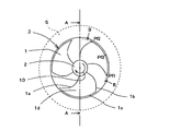
- FIG. 1 is a front view of a blower according to Embodiment 1 of the present invention as seen from the blow-out side space
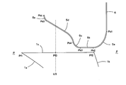
- FIG. 2 is a cross-sectional view taken along line AA in FIG. 1
- FIG. 3 is a view taken along line BB in FIG.
- FIG. 4 is a diagram in which the outer peripheral edge of the wing in the cross-section is developed on a plane and lines indicating the positions of the respective parts in the bell mouth are added.
- FIG. 4 is an enlarged view of the main part of FIG.
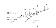
- FIG. 6 is a diagram in which a line representing the state of airflow in the vicinity of the periphery is added
- FIG. 6 is an explanatory diagram showing comparison by adding a conventional bell mouth line to FIG.
- the blower of the present embodiment drives a propeller fan 3 having a plurality of blades 1 around a hub 2 by a fan motor 7.
- the blade 1 has a joint edge with the hub 2 and a leading edge facing the rotation direction. 1a, a rear edge 1b facing the front edge 1a, an outer peripheral edge 1c facing the joint edge and connecting the front edge 1a and the rear edge 1b, and these joint edges, the front edge 1a, the rear edge 1b, and the outer peripheral edge It is formed from a curved surface surrounded by 1c.
- the surface facing the rotation direction 10 is the pressure surface 1d
- the back surface of the pressure surface 1d is the negative pressure surface 1e.
- Point Pf1 is an intersection between the front edge 1a and the outer periphery 1c
- Pf2 is an intersection between the rear edge 1b and the outer periphery 1c.
- the outer peripheral edge 1c has a concave warp in the rotation direction 10 as shown in FIG.
- the maximum warp position where the distance between the chord line 4 connecting the point Pf1 and the point Pf2 and the outer peripheral edge 1c is the maximum is the point Pf3.
- the line of the wing 1 indicates the rotation trajectory of the leading edge 1a, the trailing edge 1b, and the outer peripheral edge 1c.
- the axis serving as the rotation center of the fan motor 7 and the propeller fan 3 is referred to as a rotation axis, and the suction space direction of the rotation shaft, that is, the left side in FIG. 2 is the upstream direction of the rotation axis. That is, the right side in FIG. 2 is the downstream direction of the rotation axis.
- the outer periphery of the wing 1 is covered with a bell mouth 5.
- the bell mouth 5 is in a position that covers the entire wing outer peripheral side or a part on the rear edge 1b side.
- the baffle plate 6 is curved and forms a downstream enlarged portion 5a in which the air path expands in the downstream direction of the rotation axis.
- the baffle plate 6 isolates the suction side space ⁇ and the blowout side space ⁇ . It is connected.
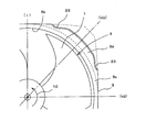
- the air passage enlarged shape in the suction side direction of the bell mouth 5 (constricted shape when viewed from the air flow direction) is as follows. That is, from the point Pb3 to the point Pb4 which is the end in the upstream direction of the rotation axis of the inner diameter minimum part 5b of the bell mouth 5, there is an upstream first enlarged portion 5c formed in a convex shape in the upstream direction of the rotation axis. From the point Pb4 to the point Pb5, there is an upstream second enlarged portion 5d formed in a concave shape in the upstream direction of the rotation axis, following the upstream first enlarged portion 5c.
- the curvature is large near the point Pb4, the curvature is small near the point Pb5, and a substantially conical section is formed near the point Pb5 that is the upstream portion.
- broken lines Lb3, Lb4, Lb5, and Lb6 are lines indicating the positions of the points Pb3, Pb4, Pb5, and Pb6 on the bell mouth 5 described above with reference to FIG.
- the broken line Lf3 is a line indicating the position of the maximum warpage position Pf3 of the outer peripheral edge 1c of the blade 1 in the rotation axis direction.
- a point Pb4 at a transition between the upstream first enlarged portion 5c and the upstream second enlarged portion 5d of the bell mouth 5 is located downstream of the maximum warp position Pf3 of the outer peripheral edge 1c of the blade 1 in the rotation axis direction. That is, the position in the rotation axis direction of the maximum warp position Pf3 of the outer peripheral edge 1c of the blade 1 is within the range included in the upstream second enlarged portion 5d.
- a part of the gas flowing into the propeller fan 3 becomes a leakage flow 8 from the pressure surface 1d to the negative pressure surface 1e via the outside of the outer peripheral edge 1c as shown in FIG.
- a flow having a vortex structure called a blade tip vortex 9 is generated at a position along the outer peripheral edge 1c of the suction surface 1e with the leakage flow 8 generated near the front edge of the outer peripheral edge 1c as a base point.
- the blade tip vortex 9 grows as it moves from the leading edge side to the trailing edge side, and departs from the outer peripheral edge 1c of the blade 1 in the vicinity of the maximum warp position Pf3 of the outer peripheral edge 1c where the flow direction is increased.
- the blade tip vortex 9 separated from the outer peripheral edge 1c is gradually discharged toward the blowout side space ⁇ while being pushed by the entire flow from the suction side space ⁇ to the blowout side space ⁇ while weakening the structure as a vortex.
- the positional relationship between the bell mouth 5 and the outer peripheral edge 1c of the wing 1 on the downstream side will be described.
- the narrowest part between the wing 1 and the bell mouth 5 is between the minimum inner diameter portion 5b from the point Pb2 to the point Pb3 and the outer peripheral edge 1c of the wing 1.
- the narrowest portion between the wing 1 and the bell mouth 5 is set near the rear edge 1b of the outer peripheral edge 1c. If this distance is too wide, the required pressure difference and flow rate cannot be obtained when the ventilation resistance before and after the blower is large.
- This gap distance is preferably about 1 to 3% of the outer diameter of the blade (rotating circle diameter of the outer peripheral edge 1c).
- the positional relationship between the bell mouth 5 and the outer peripheral edge 1c of the wing 1 on the upstream side will be described.
- the surface formed by the rotation trajectory of the outer peripheral edge 1c of the blade 1 serves as an airflow inflow surface. Obtaining inflow from a large area has the effect of reducing the speed of the airflow at the same flow rate and reducing noise. From this point of view, it is desirable that the distance between the bell mouth 5 and the outer peripheral edge 1c of the wing 1 on the upstream side, that is, the inflow side of the airflow is sufficiently wide.
- the outer peripheral edge 1c of the blade 1 is a place where the blade tip vortex 9 is generated, grows, and further leaves.
- the blade tip vortex 9 is a flow having a large turbulence, and if there is a wall surface such as the bell mouth 5 nearby, the pressure fluctuation on the wall surface becomes large and becomes a noise factor. From this point of view, it is desirable that the distance between the bell mouth 5 on the upstream side and the outer peripheral edge 1c of the wing 1 is sufficiently wide.
- the distance between the bell mouth 5 and the outer peripheral edge 1c of the blade 1 is set to the vicinity of the rear edge 1b.
- the distance between the outer periphery 1c of the wing 1 and the bell mouth 5 is increased while surrounding the outer periphery 1c of the wing 1. It is desirable to suppress an increase in noise due to the nonuniformity of the air path shape.
- the blower of the present embodiment has the upstream second enlarged portion 5d formed in a concave shape in the upstream direction of the rotation axis, following the upstream first enlarged portion 5c formed in a convex shape in the upstream direction of the rotation axis, the blower from FIG.
- the outer side of the blade 1 is larger than the shape in which the upstream side expands with a curved cross section 11 (shown by a wavy line in the figure) formed in a convex shape in the upstream direction of the rotation axis from the minimum inner diameter portion that is generally used conventionally. It can be seen that the distance between the outer peripheral edge 1c of the wing 1 and the bell mouth 5 can be increased while surrounding the peripheral edge 1c.
- the air path around the outer peripheral edge 1c of the blade 1 can be made uniform in the circumferential direction, and fluctuations in the airflow flowing into the blade 1 can be suppressed, and a blower with low noise can be obtained. Furthermore, since the shape from the upstream side in the axial direction of the upstream second enlarged portion 5d to the minimum inner diameter position Pb3 can be made smoothly, the effect of suppressing turbulence in airflow is high, and noise can be reduced efficiently. it can.
- the curvature is large in the vicinity of the upstream first enlarged portion 5c, the curvature is further reduced on the upstream side, and the upstream portion has a substantially conical section, so the upstream second enlarged portion 5d.
- the opening area can be widened on the upstream side in the axial direction, and a large amount of airflow can be guided to the space between the outer peripheral edge 1 c and the bell mouth 5. Therefore, a blower with a large air volume and low noise can be obtained.
- the upstream third enlarged portion 5e formed in a convex shape in the upstream direction of the rotation axis following the upstream second enlarged portion 5d, the airflow flowing from the bell mouth end portion is transferred to the upstream large third enlarged portion 5e. It can guide to the wing
- the transition portion Pb4 between the upstream first enlarged portion 5c and the upstream second enlarged portion 5d of the bell mouth 5 is positioned on the downstream side in the rotational axis direction from the maximum warp position Pf3 of the outer peripheral edge 1c of the blade 1. Therefore, in the vicinity of the maximum warp position Pf3, the distance between the outer peripheral edge 1c of the wing 1 and the bell mouth 5 is large, and therefore the pressure fluctuation on the bell mouth wall surface can be suppressed.
- the position of the maximum warpage position Pf3 of the outer peripheral edge 1c of the blade 1 in the rotation axis direction is within the range included in the upstream second enlarged portion 5d, the surrounding air current is disturbed when the blade tip vortex 9 is detached. And the turbulence of the blade tip vortex 9 can be made small. As a result, noise caused by the detached blade tip vortex 9 can also be suppressed.
- the position in the rotation axis direction of the maximum warp position Pf3 of the outer peripheral edge 1c of the blade 1 has been described as being in a range included in the upstream second enlarged portion 5d. The same effect can be obtained in the case of the included range.
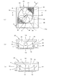
- FIG. 7 and 8 show a heat pump device, that is, an air conditioner according to Embodiment 2 of the present invention.
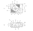
- FIG. 7 is a front view (a) of a rectangular box type outdoor unit of the air conditioner and its CC.
- FIG. 8 is a horizontal sectional view including the rotation axis as viewed in the direction of the arrow, and
- FIG. 8 is a diagram for explaining the direction of the air passage viewed from the rotation axis.
- FIG. The same reference numerals are given. In the description of the blower, reference is made to FIG. 1 to FIG. 6 described above.
- the air conditioner of this embodiment that is, a rectangular parallelepiped outdoor unit 12, is provided with a blow-out surface 13 on the front surface, and is provided with an external air suction surface 14 on the opposite surface (back surface) and one side surface on the left side of the drawing.
- a heat exchanger 15 bent in an L shape so as to block these suction surfaces 14 is installed, and a blower is disposed in the vicinity of the heat exchanger 15.
- This blower is composed of the blower of the first embodiment.
- the heat exchanger 15 is provided with a multi-layered fin for heat transfer on the outer surface of the pipe through which the refrigerant circulates, and is not necessarily formed in an L shape, for example, only on the back side. It is also good to provide.
- the side surface surrounding the blowing surface 13 of the box is formed from a plurality of side plates.
- a grill 16 that protects the propeller fan 3 or protects a person or the like from the propeller fan 3 that is a rotating body is disposed on the downstream side in the rotation axis direction of the blower.
- the blowout surface 13 and the bell mouth 5 are surrounded by a heat exchanger 15, an upper surface plate 17, a lower surface plate 18, and a separation plate 22.
- the separation plate 22 partitions the in-machine air passage chamber 19 that houses the blower in the outdoor unit 12 and the compressor chamber 21 that houses the compressor 20.
- the blade 1 of the propeller fan 3 has a concave warp in the rotation direction 10 at the outer peripheral edge 1c as described in FIG.
- the bell mouth 5 that surrounds the entire outer peripheral side of the blade or the rear edge side of the propeller fan 3 is point Pb2 to point Pb3 in any of the directions (i) to (viii) shown in FIG.
- the minimum inner diameter portion 5b having the smallest distance from the outer peripheral edge 1c of the blade 1 covers the vicinity of the rear edge 1b of the outer peripheral edge 1c.
- it has the downstream expansion part 5a which curves from the point Pb2 to the point Pb1, and an air path expands to a rotating shaft downstream direction.
- the air passage enlarged shape in the suction side direction (constricted shape when viewed from the airflow direction) is formed in a convex shape in the upstream direction of the rotational axis from the end point Pb3 to the point Pb4 in the upstream direction of the rotational axis of the minimum inner diameter portion 5b.
- An upstream first enlarged portion 5c is provided. From the point Pb4 to the point Pb5, there is an upstream second enlarged portion 5d formed in a concave shape in the upstream direction of the rotation axis, following the upstream first enlarged portion 5c.
- the curvature is large near the point Pb4, the curvature is small near the point Pb5, and a substantially conical section is formed near the point Pb5 that is the upstream portion.
- the end point Pb3 in the upstream direction of the rotational axis of the inner diameter minimum portion 5b of the bell mouth 5 is the end portion on the trailing edge side of the outer peripheral edge 1c of the blade 1 as shown in FIG. It is on the upstream side in the rotational axis direction from Pb2.
- the transition portion Pb4 between the upstream first enlarged portion 5c and the upstream second enlarged portion 5d is located on the downstream side in the rotational axis direction from the maximum warp position Pf3 of the outer peripheral edge 1c of the blade 1. That is, the position in the rotation axis direction of the maximum warp position Pf3 of the outer peripheral edge 1c of the blade 1 is within the range included in the upstream second enlarged portion 5d.
- the operation of the air conditioner of this embodiment configured as described above, that is, the outdoor unit 12 will be described.
- the gas in the in-machine air duct chamber 19, which is the region in which the propeller fan 3 rotates is pushed out from the blowing surface 13 to the blowing side space ⁇ , and outside the apparatus, that is, the suction side.
- the gas in the space ⁇ flows from the suction surface 14 through the fins of the heat exchanger 15 into the in-machine air passage chamber 19 where the propeller fan 3 rotates.
- a refrigerant having a temperature higher or lower than the temperature of the gas outside the machine circulates inside the heat exchanger 15, and heat exchange is performed when the gas outside the machine passes through the heat exchanger 15.
- the gas whose temperature has increased or decreased by exchanging heat with the heat exchanger 15 when flowing into the in-machine air duct chamber 19 is blown out of the apparatus by the rotation of the propeller fan 3 as described above.
- the operation of the airflow around the blades of the propeller fan 3 is the same as in the first embodiment. That is, a part of the gas flowing into the propeller fan 3 becomes a leakage flow 8 from the pressure surface 1d to the negative pressure surface 1e via the outside of the outer peripheral edge 1c as shown in FIG. Then, a blade tip vortex 9 is generated at a position along the outer peripheral edge 1c of the suction surface 1e with the leakage flow 8 generated in the vicinity of the front edge of the outer peripheral edge 1c as a base point, and grows as this moves from the front edge side to the rear edge side. In the vicinity of the maximum warp position Pf3 of the outer peripheral edge 1c where the flow direction is increased, the blade 1 is separated from the outer peripheral edge 1c.
- the blade tip vortex 9 separated from the outer peripheral edge 1c is pushed by the overall flow from the inboard air passage chamber 19 to the outside of the aircraft while weakening the structure as a vortex, and is gradually discharged to the outside of the aircraft from the blowing surface 13. .
- the air conditioner of this embodiment comprises the air blower for accelerating
- the distance from the wing 1 to the wind path end other than the bell mouth 5 is, for example, as shown in (i), (iii), (v), (vii) of FIG. It is narrow in the direction and wide in the directions (ii), (iv), (vi), and (viii).
- Embodiment 3 FIG.
- an air conditioner in which the bell mouth 5 around the propeller fan 3 includes the upstream second enlarged portion 5d and the upstream third enlarged portion 5e on the upstream side in the entire circumferential direction is taken as an example.
- the upstream second enlarged portion 5d of the bell mouth 5 and the upstream third enlarged portion 5e on the upstream side of the bell mouth 5 have a sudden distance in the circumferential direction from the wing 1 to the wind path end other than the bell mouth 5.
- the initial object can be achieved even if it is provided only in the part that changes, for example, the part corresponding to the corner of the rectangular box-type outdoor unit 12 (the part having a long distance to the end of the air passage).
- the heat pump apparatus that is, the outdoor unit 12 of the air conditioner, having an upstream portion including the upstream second enlarged portion 5d only partially in the circumferential direction of the bell mouth 5 will be described with reference to FIGS. explain.
- FIG. 9 is a front view (a) of an outdoor unit of an air conditioner according to Embodiment 3 of the present invention, a horizontal sectional view (b) including a rotational axis that is a sectional view taken along line DD, and a rotational axis thereof.
- FIG. 10 is a diagram for explaining the direction of the air passage viewed from the rotation axis, FIG. It is a figure and the same code
- the above-described FIGS. 1 to 6 are referred to.
- the blade 1 of the propeller fan 3 of the blower has a concave warp (see FIG. 3) in the rotation direction 10 at the outer peripheral edge 1c.
- the bell mouth 5 that surrounds the entire outer peripheral side or the rear edge side of the wing of the propeller fan 3 is in the directions (i), (iii), (v), (vii) shown in FIG.
- the upstream shape of the bell mouth 5 stops at the upstream first enlarged portion 5c (see FIG. 4), as shown in FIG. 9B.
- the direction of the corners of the side surface surrounding the blowout surface 13 that is, the direction of the corners (ii) and (iv) consisting of the separation plate 22, the upper surface plate 17 and the lower surface plate 18, the heat exchanger 15 and the lower surface plate 18 and
- the bell mouth 5 in the direction of the corners (vi) and (viii) formed by the upper surface plate 17 is connected to the outer peripheral edge 1c of the blade 1 from the point Pb2 to the point Pb3 as described in the first embodiment with reference to FIG.
- the inner diameter minimum portion 5b having the smallest distance covers the vicinity of the rear edge 1b of the outer peripheral edge 1c.
- the air path enlarged shape in the suction side direction (constricted shape when viewed from the airflow direction) is convex from the point Pb3 to the point Pb4 which is the end of the inner diameter minimum portion 5b in the upstream direction of the rotation axis, in the upstream direction of the rotation axis.
- the first upstream enlarged portion 5c is formed. From the point Pb4 to the point Pb5, there is an upstream second enlarged portion 5d formed in a concave shape in the upstream direction of the rotation axis, following the upstream first enlarged portion 5c.
- the curvature is large near the point Pb4, the curvature is small near the point Pb5, and a substantially conical section is formed near the point Pb5 that is the upstream portion.
- the inner diameter of the bell mouth 5 is minimized.
- An end point Pb3 in the upstream direction of the rotation axis of the portion 5b is located on the upstream side in the rotation axis direction from the rear edge side end portion Pb2 of the outer peripheral edge 1c of the blade 1.
- the transition portion Pb4 between the upstream first enlarged portion 5c and the upstream second enlarged portion 5d is located on the downstream side in the rotational axis direction from the maximum warp position Pf3 of the outer peripheral edge 1c of the blade 1.
- the position in the rotation axis direction of the maximum warp position Pf3 of the outer peripheral edge 1c of the blade 1 is within a range included in the upstream second enlarged portion 5d.
- the air conditioner that is, the outdoor unit 12 of the present embodiment is also characterized by the shape of the bell mouth 5 around the propeller fan 3 and the positional relationship between the propeller fan 3 and the bell mouth 5. Therefore, as in the first and second embodiments, a large amount of airflow can be taken from the outer peripheral edge 1c of the blade 1 of the blower, and the pressure fluctuation on the surface of the bell mouth 5 due to the turbulence of the blade tip vortex 9 is suppressed. can do.
- the effect which suppresses disturbance of an air current is high and noise can be reduced efficiently.
- the distance from the wing 1 to the wind path end other than the bell mouth 5 changes rapidly in the circumferential direction (ii), (iv), (vi), (viii) in FIG.
- the upstream second enlarged portion 5d and the upstream third enlarged portion 5e on the upstream side cover the outer periphery of the blade, it is possible to efficiently suppress the variation of the flowing air flow and the blade tip vortex 9 and obtain a low noise effect. It is done.
- the upstream portion including the upstream second enlarged portion 5d of the bell mouth 5 is only partially present in the circumferential direction of the outer peripheral edge 1c.
- the diameter of the propeller fan 3 can be increased instead.
- the number of fan rotations for obtaining the required air volume can be reduced, so that the low noise effect can be enhanced.
- the speed of the gas blown out from the propeller fan 3 and flowing into the grill 16 can be reduced, the noise generated from the grill 16 can be reduced, and thus the low-noise outdoor unit 12 can be obtained.
- the ventilation resistance of the grille 16 can be lowered by reducing the velocity of the gas passing through the grille 16, the required power can be reduced and the outdoor unit 12 having a high energy saving effect can be obtained.
- the low ventilation resistance of the grill 16 means that the required pressure increase of the propeller fan 3 can be reduced. From this point, the noise of the propeller fan 3 can be reduced, and the outdoor unit 12 with lower noise can be obtained. .
- the bell mouth 5 is formed in a convex shape in the rotational axis direction at both ends in the circumferential direction of the upstream second enlarged portion 5d as shown in FIG. 11 which is represented by a cross section perpendicular to the rotational axis in the region of the upstream second enlarged portion 5d. It has an end warp 23 that is a curved surface. Accordingly, a transition portion from the portion where the upstream second enlarged portion 5d exists in the circumferential direction to the portion where it does not exist, for example, a transition portion from the (vii) direction to the (viii) direction and from the (viii) direction to the (i) direction. It can be formed smoothly, and fluctuations due to separation of the airflow flowing into the bell mouth 5 can be suppressed even at the transition portion, and a low noise effect can be easily obtained.
- FIG. 12 is a front view (a) of a cuboid box type outdoor unit of a heat pump device, that is, a heat pump type hot water heater according to Embodiment 4 of the present invention, and a horizontal sectional view including a rotation axis that is a sectional view taken along line FF.
- FIG. 5B is a cross-sectional view taken along line GG including the rotation axis thereof, and the same reference numerals are given to the same portions as those in the first and third embodiments described above.
- FIGS. 1 to 6 are referred to.
- the blower has the same configuration as that of the above-described third embodiment, and thus the description thereof is omitted, and the configuration mainly with the third embodiment.
- the heat pump type water heater of the present embodiment is provided with a blow-out surface 13 on the front surface of the outdoor unit 25, and an external air suction surface 14 is provided on the opposite surface (back surface) and one side surface on the left side of the drawing.
- the heat exchanger 15 bent in an L shape so as to close the suction surface 14 is installed.
- a water heat exchanger 24 that performs heat exchange between the refrigerant and water is installed in the lower part of the in-flight air passage chamber 19.
- the water heat exchanger 24 occupies the lower part of the in-flight air passage chamber 19.
- the lower surface plate 18 in the above-described third embodiment is replaced with the upper surface 24 a of the water heat exchanger 24.
- FIG. 5 the blower according to the present embodiment is characterized in that the outer peripheral edge side of the blade 1 is warped from the blowing side ( ⁇ ) to the suction side ( ⁇ ).
- ⁇ the blowing side
- ⁇ the suction side
- FIG. 13 is an enlarged view of a main part corresponding to FIG. 4 of the blower according to Embodiment 5 of the present invention.
- Broken lines Ld1 to Ld11 equally divide the radial cross section of the blade centering on the rotation axis, and set the dividing point as a hub.
- the meridian is a divided meridian obtained by rotating a line connecting from the side to the outer peripheral edge about the rotational axis and projecting it on a plane including the rotational axis, and shows the outer peripheral side from half of the meridian.
- the front edge to the rear edge are divided into 12 parts.
- the dividing meridian is warped from the blowing side (blowing space ⁇ side) to the suction side (suction space ⁇ side) before and after Lf4 drawn on the blade outer circumferential side.
- the warping method shown in this figure is large from Ld5 to Ld7, which is near the middle from the leading edge to the trailing edge, and gradually decreases from the leading edge to the trailing edge.
- the leading edge 1a and the trailing edge 1b (represented as meridian in FIG. 13) are not warped.
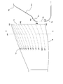
- FIG. 14 is a view in which the outer peripheral edge of the blade is developed in a plane as in FIG. 5 and a line indicating the state of the airflow near the outer peripheral edge is added.
- a part of the gas flowing into the propeller fan 3 becomes a leakage flow 8 from the pressure surface 1d to the negative pressure surface 1e via the outside of the outer peripheral edge 1c as shown in FIG.
- the blade outer peripheral edge side is bent toward the suction side, the pressure difference between the pressure surface 1d and the negative pressure surface 1e at the outer peripheral edge 1c is reduced, and the leakage flow 8 flowing from the pressure surface 1d to the negative pressure surface 1e is generated. Smooth.
- the central pressure of the blade tip vortex 9 generated at the position along the outer peripheral edge 1c of the suction surface 1e with the leakage flow 8 generated in the vicinity of the front edge of the outer peripheral edge 1c as a base point is compared with the case where the outer peripheral edge side is not deflected to the suction side. It becomes high and becomes weak as a vortex.
- the blade tip vortex 9 grows as it moves from the leading edge 1a side to the trailing edge 1b side, and departs from the outer peripheral edge 1c of the blade 1 in the vicinity of the maximum warp position Pf3 of the outer peripheral edge 1c where the flow direction is increased.
- the blade tip vortex 9 separated from the outer peripheral edge 1c is gradually discharged toward the blowout side space ⁇ while being pushed by the entire flow from the suction side space ⁇ to the blowout side space ⁇ while weakening the structure as a vortex.
- the vortex separated from the outer peripheral edge 1c interferes with the bell mouth 5 and adjacent wings and becomes a noise source, and also serves as a resistance that inhibits the flow from the suction side space ⁇ to the blowout side space ⁇ , thereby obtaining a required air volume and pressure. For this reason, the fan speed is increased and noise increases.
- the blade tip vortex 9 can be weakened, and an increase in noise due to the blade tip vortex 9 can be suppressed.
- the blade tip vortex 9 when the blade outer peripheral edge is bent toward the suction side becomes an unstable vortex in which the vortex position and the vortex diameter are easily changed, although the central pressure is relatively high and the vortex becomes weak.
- the conventional bell mouth 25 which has only an upstream 1st enlarged part as shown in FIG. 15, the effect cannot fully be acquired.
- the periphery of the blade 1 is sufficiently wide and uniform in the circumferential direction in the suction side space ⁇ .
- the weak and unstable blade tip vortex 9 is more unstable because it is easily affected by surrounding fluctuations, and causes noise in the flow field.
- the air path around the outer peripheral edge 1c of the blade 1 can be made uniform in the circumferential direction, the fluctuation of the airflow flowing into the blade 1 can be suppressed, and the instability of the blade tip vortex is suppressed.
- a large amount of airflow can be taken from the outer peripheral edge 1 c of the blade 1, and separation of the blade tip vortex 9 can be suppressed.
- the low noise action of the propeller fan 3 in which the outer peripheral edge side of the blade 1 is bent toward the suction side can be effectively obtained, and a blower with low noise can be obtained.
- the warping method in which the outer peripheral edge side shown in FIG. 13 is warped from the blowing side toward the suction side is large near the middle from the front edge 1a to the rear edge 1b, and the warping amount gradually decreases toward the rear edge 1b. It does not warp at the trailing edge 1b which is the end of the divided meridian. In this way, the inflow of gas from the outer peripheral edge 1c of the blade 1 is reduced by the bell mouth 5, and the generation of the blade tip vortex 9 and the leakage flow 8 serving as a growth source are reduced.
- By reducing the warpage from the side to the suction side it is possible to effectively increase the blade pressure by obtaining a large turning angle on the outer peripheral edge having a large peripheral speed.
- a decrease in the relative velocity of the airflow on the blade surface means a decrease in pressure fluctuation that causes noise, and a low noise blower can be obtained.
- Embodiment 6 the blade outer peripheral side of the propeller fan 3 is warped from the blow-out side to the suction side, and the upstream second enlarged portion 5d is continuously provided upstream from the upstream first enlarged portion 5c of the bell mouth 5 in the circumferential direction.
- a heat pump device including a blower having, for example, an air conditioner will be described with reference to FIGS. In the description of the blower, reference is made to FIG. 1 to FIG. 6 described above.
- the air conditioner to which the blower of the present embodiment is applied has the same configuration and operation as those of the second embodiment, and the effects of the second embodiment can be obtained in the same manner.
- wing 1 of the propeller fan 3 to the suction side is mainly demonstrated.
- the bell mouth is provided with the upstream second enlarged portion on the entire circumference in the circumferential direction continuously from the upstream first enlarged portion, and the outer peripheral side of the blade 1 of the propeller fan 3 is provided. Since it is warped to the suction side, the influence of the nonuniformity of the air path around the outer peripheral edge can be suppressed, the inflow of gas from the outer peripheral edge 1c can be ensured, and the blade vortex 9 can be weakened to reduce noise. An effect can be obtained. Therefore, a low noise heat pump device can be obtained.
- Embodiment 7 FIG.
- the blade outer peripheral side of the propeller fan 3 is warped from the blow-out side to the suction side, and the upstream second enlarged portion 5d is partly arranged in the circumferential direction continuously upstream from the upstream first enlarged portion 5c of the bell mouth 5.
- a heat pump device for example, an air conditioner will be described. In the description of the blower, reference is made to FIG. 1 to FIG. 6 described above.
- the air conditioner to which the blower of the present embodiment is applied has the same configuration and operation as those of the third embodiment described with reference to FIGS. 10 and 11, and the effects of the third embodiment can be obtained in the same manner.
- wing 1 of the propeller fan 3 to the suction side is mainly demonstrated.
- the bell mouth is continuous from the upstream first enlarged portion 5c, and the upstream second enlarged portion 5d is upstream of the upstream side. Since it is provided in a portion where the change is large as viewed from the outside, it is possible to effectively suppress the influence of the nonuniformity of the air passage around the outer peripheral edge, and to ensure the inflow of gas from the outer peripheral edge 1c, and to the blade tip The vortex 9 can be weakened to obtain a low noise effect. Therefore, a low noise heat pump device can be obtained.
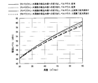
- FIGS. 16 and 17 show the angle formed by the separation plate, the upper plate, and the lower plate in the outdoor unit when the outer peripheral side of the blade 1 of the propeller fan 3 is warped to the suction side in the outdoor unit of the air conditioner. It is a graph which shows the result of having tested the relationship between an air volume and an aerodynamic noise level combining the case where an upstream 2nd expansion part is provided in the upstream of the bellmouth upstream 1st expansion part, and the case of the conventional bell mouth. . 16 and 17 are different in the shape of warping the outer peripheral edge side of the blade 1.
- the blade shape tested in FIG. 16 is called propeller fan A
- the blade shape tested in FIG. 17 is called propeller fan B.
- FIG. 18 shows a divided meridian like FIG. The angle of difference before and after the change of the dividing meridian is changed to ⁇ , and in propeller fan A, ⁇ at the central dividing meridian from the leading edge 1a to the trailing edge 1b, that is, dividing meridian Ld6 in FIG. Yes.
- ⁇ at the dividing meridian on the leading edge 1a side of the center that is, the dividing meridian Ld4 in FIG.
- the radius position that is the base point where the inclination of the dividing meridian changes is set to 85% radius of the outer peripheral diameter.
- FIG. 19 is a development view of the outer peripheral edge of the wing 1, where the length of the chord line is L, the maximum distance between the chord line and the wing is D, and the warp ratio is defined as D / L.
- the warp ratio is increased to 5.8% at the radius ratio of 85% and 8.7% at the outer radius position to realize the gradient of the divided meridian.
- the noise of the outdoor unit can be reduced by providing the second enlarged portion upstream of the conventional bell mouth when the outer peripheral edge of the wing is not bent toward the suction side.
- the noise of the outdoor unit can hardly be reduced with the conventional bell mouth, but it can be seen that the noise of the outdoor unit can be greatly reduced by providing the upstream second enlarged portion.
- the outdoor unit 12 of the air conditioner and the outdoor unit 25 of the heat pump type hot water heater have been described as examples.
- various devices for example, a ventilation fan in which the blower is installed, It can be widely used for facilities.
Landscapes
- Engineering & Computer Science (AREA)
- Mechanical Engineering (AREA)
- General Engineering & Computer Science (AREA)
- Chemical & Material Sciences (AREA)
- Combustion & Propulsion (AREA)
- Structures Of Non-Positive Displacement Pumps (AREA)
Abstract
Description
1c 外周縁
Pb3 内径最小位置
Pb4 点(移行部)
Pf3 最大反り位置
5 ベルマウス
5c 上流第一拡大部
5d 上流第二拡大部
5e 上流第三拡大部
13 吹出し面
15 熱交換器(側面)
17 箱体の上面
18 下面板(側面)
22 分離板(側面)
23 端部反り(曲面)
以下、図示実施形態により本発明を説明する。
図1は本発明の実施の形態1に係る送風機を吹出し側空間から見た正面図、図2は図1のA-A線矢視断面図、図3は図1のB-B線矢視断面における翼の外周縁を平面に展開しこれにベルマウスにおける各部の位置を表す線を付加した図、図4は図2の要部拡大図、図5は図3の図にさらに翼の外周縁付近の気流の状態を表す線を付加した図、図6は図2に従来のベルマウスのラインを付加し比較して示す説明図である。
前述のように構成された送風機において、ファンモータ7の駆動力によりプロペラファン3が回転すると、プロペラファン3が回転する領域内の気体が吹出し側空間βに押し出されるとともに、吸込み側空間αの気体がプロペラファン3の回転する領域に流入する。プロペラファン3へは、翼前縁1aの回転軌跡からなる面や、翼1の外周縁1cの回転軌跡からなる面から気体が流入する。このようにして吸込み側空間αから吹出し側空間βへと気流が生じる。
図7及び図8は本発明の実施の形態2に係るヒートポンプ装置すなわち空気調和機を示すもので、図7は空気調和機の直方体箱型の室外機の正面図(a)とそのC-C線矢視断面である回転軸を含む水平断面図(b)、図8は回転軸から見た風路の方向を説明する図であり、図7中、前述の実施形態1と同一部分には同一符号を付してある。なお、送風機の説明にあたっては前述の図1乃至図6を参照するものとする。
前述の実施形態2では、ヒートポンプ装置として、プロペラファン3周囲のベルマウス5が周方向全体に上流第二拡大部5d及びその上流側の上流第三拡大部5eを備える空気調和機を例に挙げて説明したが、ベルマウス5の上流第二拡大部5d及びその上流側の上流第三拡大部5eは、翼1から見たベルマウス5以外の風路端までの距離が周方向において急激に変化する部分、例えば直方体箱型の室外機12のコーナに対応する部分(風路端までの距離が長い部分)にのみ設けても初期の目的は達成できるものである。以下、ベルマウス5の周方向に部分的にしか上流第二拡大部5dを含む上流の部分を備えていないような形態のヒートポンプ装置すなわち空気調和機の室外機12について図9乃至図11に基づき説明する。
図12は本発明の実施の形態4に係るヒートポンプ装置すなわちヒートポンプ式給湯機の直方体箱型の室外機の正面図(a)とそのF-F線矢視断面である回転軸を含む水平断面図(b)とその回転軸を含むG-G線矢視断面図(c)であり、図中、前述の実施形態1及び実施形態3と同一部分には同一符号を付してある。なお、ここでも送風機の説明にあたっては前述の図1乃至図6を参照するものとする。
本実施の形態の送風機は、前述の実施形態1で述べた特徴に加えて、翼1の外周縁側を吹出し側(β)から吸込み側(α)へと反らせたことを特徴とする。先ず翼外周縁側を吹出し側から吸込み側へ反らせる形状について説明する。翼形状以外のベルマウス5の特徴やプロペラファン3とベルマウス5との相対位置、ファンモータ7との構成などは実施形態1と同じである。したがって、ここでも送風機の説明にあたっては前述の図1乃至図6を参照するものとする。
ここでは、プロペラファン3の翼外周縁側を吹出し側から吸込み側へ反らせるとともに、ベルマウス5の上流第一拡大部5cから連続してその上流側に上流第二拡大部5dを周方向全周に有する送風機を備えたヒートポンプ装置、例えば空気調和機について前述の図7及び図8を用いて説明する。なお、送風機の説明にあたっては前述の図1乃至図6を参照するものとする。
ここでは、プロペラファン3の翼外周縁側を吹出し側から吸込み側へ反らせるとともに、ベルマウス5の上流第一拡大部5cから連続してその上流側に上流第二拡大部5dを周方向に部分的に備えるヒートポンプ装置、例えば空気調和機について説明をする。なお、送風機の説明にあたっては前述の図1乃至図6を参照するものとする。
Claims (17)
- 回転方向に凹状の反りを持つ外周縁を有する翼と、該翼の吹出し側外周を覆うベルマウスとを備えた送風機において、
前記ベルマウスの翼側面を、
内径最小位置から上流側に延出して回転軸上流方向に凸状に形成された上流第一拡大部と、
前記上流第一拡大部から連続して更に上流側に延出して回転軸上流方向に凹状に形成された上流第二拡大部と、
から構成したことを特徴とする送風機。 - 前記上流第二拡大部は、その上流部分が概ね円錐状に形成されていることを特徴とする請求項1記載の送風機。
- 前記上流第一拡大部から前記上流第二拡大部への移行部が、前記翼の外周縁の最大反り位置よりも下流側にあることを特徴とする請求項1又は請求項2記載の送風機。
- 前記上流第二拡大部から連続して更に上流側に延出して回転軸上流方向に凸状に形成された上流第三拡大部を有することを特徴とする請求項1乃至請求項3のいずれかに記載の送風機。
- 前記上流第二拡大部または前記上流第三拡大部が前記翼の外周縁の最大反り部分を覆うことを特徴とする請求項4記載の送風機。
- プロペラファンの翼の外周縁側を吹出し側から吸込み側に反らせたことを特徴とする請求項1乃至請求項5のいずれかに記載の送風機。
- プロペラファンの翼の外周縁側を吹出し側から吸込み側に反らせた形状が、前縁から後縁までの中間付近から後縁にかけて、反り方が徐々に小さくなることを特徴とする請求項6に記載の送風機。
- 箱体の上面または側面に設けられて送風機が配置された空気吹出し面と、少なくとも他の1面に設けられた熱交換器と、その他の面を囲む複数の側板または熱交換器を有するヒートポンプ装置であって
前記送風機が、回転方向に凹状の反りを持つ外周縁を有する翼と、該翼の吹出し側外周を覆うベルマウスとを備え、
前記ベルマウスの翼側面が、
内径最小位置から全周に形成されて上流側に延出し回転軸上流方向に凸状に形成された上流第一拡大部と、
前記上流第一拡大部から連続して全周に形成されて更に上流側に延出し回転軸上流方向に凹状に形成された上流第二拡大部とからなることを特徴とするヒートポンプ装置。 - 前記送風機が、請求項2乃至請求項7のいずれかに記載の送風機であることを特徴とする請求項8記載のヒートポンプ装置。
- プロペラファンの翼の外周縁側を吹出し側から吸込み側に反らせたことを特徴とする請求項8又は請求項9記載のヒートポンプ装置。
- 箱体の上面または側面に設けられて送風機が配置された空気吹出し面と、少なくとも他の1面に設けられた熱交換器と、その他の面を囲む複数の側板または熱交換器を有するヒートポンプ装置であって
前記送風機が、回転方向に凹状の反りを持つ外周縁を有する翼と、該翼の吹出し側外周を覆うベルマウスとを備え、
前記ベルマウスの翼側面が、
内径最小位置から全周に形成されて上流側に延出し回転軸上流方向に凸状に形成された上流第一拡大部と、
前記上流第一拡大部から連続して全周のうち部分的に形成されて更に上流側に延出し回転軸上流方向に凹状に形成された上流第二拡大部とからなることを特徴とするヒートポンプ装置。 - 前記送風機が、請求項2乃至請求項7のいずれかに記載の送風機であることを特徴とする請求項11記載のヒートポンプ装置。
- 前記ベルマウスの前記上流第二拡大部の周方向両端部に、回転軸方向に凸状に形成された曲面を有することを特徴とする請求項11又は請求項12記載のヒートポンプ装置。
- 前記ベルマウスの前記上流第一拡大部から部分的に上流側に延びる前記上流第二拡大部がある周方向位置は、前記箱体の前記空気吹出し面を囲む側面の角部に対応する位置であることを特徴とする請求項11乃至請求項13のいずれかに記載のヒートポンプ装置。
- 前記箱体の吹出し面を囲む側面は、複数の側板からなることを特徴とする請求項14記載のヒートポンプ装置。
- 前記箱体の吹出し面を囲む側面は、複数の側板と熱交換器とからなることを特徴とする請求項14記載のヒートポンプ装置。
- プロペラファンの翼の外周縁側を吹出し側から吸込み側に反らせたことを特徴とする請求項11乃至請求項16のいずれかに記載のヒートポンプ装置。
Priority Applications (5)
| Application Number | Priority Date | Filing Date | Title |
|---|---|---|---|
| ES09734028T ES2702364T3 (es) | 2008-04-22 | 2009-03-11 | Soplador y dispositivo de bomba de calor que usa el mismo |
| US12/933,838 US20110017427A1 (en) | 2008-04-22 | 2009-03-11 | Blower and heatpump using the same |
| JP2010509112A JP5213953B2 (ja) | 2008-04-22 | 2009-03-11 | 送風機およびこの送風機を用いたヒートポンプ装置 |
| CN200980114335.3A CN102016327B (zh) | 2008-04-22 | 2009-03-11 | 送风机及使用该送风机的热泵装置 |
| EP09734028.5A EP2270338B1 (en) | 2008-04-22 | 2009-03-11 | Blower and heat pump device using same |
Applications Claiming Priority (4)
| Application Number | Priority Date | Filing Date | Title |
|---|---|---|---|
| JP2008111585 | 2008-04-22 | ||
| JP2008-111585 | 2008-04-22 | ||
| JP2008228399 | 2008-09-05 | ||
| JP2008-228399 | 2008-09-05 |
Publications (1)
| Publication Number | Publication Date |
|---|---|
| WO2009130954A1 true WO2009130954A1 (ja) | 2009-10-29 |
Family
ID=41216695
Family Applications (1)
| Application Number | Title | Priority Date | Filing Date |
|---|---|---|---|
| PCT/JP2009/054645 Ceased WO2009130954A1 (ja) | 2008-04-22 | 2009-03-11 | 送風機およびこの送風機を用いたヒートポンプ装置 |
Country Status (5)
| Country | Link |
|---|---|
| US (1) | US20110017427A1 (ja) |
| EP (1) | EP2270338B1 (ja) |
| JP (1) | JP5213953B2 (ja) |
| ES (1) | ES2702364T3 (ja) |
| WO (1) | WO2009130954A1 (ja) |
Cited By (7)
| Publication number | Priority date | Publication date | Assignee | Title |
|---|---|---|---|---|
| JP2010236372A (ja) * | 2009-03-30 | 2010-10-21 | Daikin Ind Ltd | 軸流送風機、空気調和機及び換気扇 |
| JP2011185236A (ja) * | 2010-03-11 | 2011-09-22 | Mitsubishi Electric Corp | 送風機及びヒートポンプ装置 |
| US8616844B2 (en) | 2010-05-12 | 2013-12-31 | Deere & Company | Fan and shroud assembly |
| US20180363928A1 (en) * | 2016-01-25 | 2018-12-20 | Mitsubishi Electric Corporation | Outdoor unit and air conditioner including the same |
| WO2021084605A1 (ja) * | 2019-10-29 | 2021-05-06 | 三菱電機株式会社 | 空気調和装置の室外機 |
| JP2023004047A (ja) * | 2021-06-25 | 2023-01-17 | 株式会社やまびこ | 軸流ブロワ |
| WO2023079697A1 (ja) * | 2021-11-05 | 2023-05-11 | 三菱電機株式会社 | プロペラファン、送風機および空気調和機 |
Families Citing this family (10)
| Publication number | Priority date | Publication date | Assignee | Title |
|---|---|---|---|---|
| KR101724294B1 (ko) * | 2010-10-27 | 2017-04-07 | 엘지전자 주식회사 | 공기조화기의 실외기 |
| WO2013094082A1 (ja) * | 2011-12-19 | 2013-06-27 | 三菱電機株式会社 | 室外機及びこの室外機を備えた冷凍サイクル装置 |
| US10222085B2 (en) | 2012-02-29 | 2019-03-05 | Carrier Corporation | Energy recovery ventilator with reduced power consumption |
| US9835176B2 (en) * | 2013-04-05 | 2017-12-05 | Acoustiflo Llc | Fan inlet air handling apparatus and methods |
| JP2017053295A (ja) * | 2015-09-11 | 2017-03-16 | 三星電子株式会社Samsung Electronics Co.,Ltd. | 送風機および室外機 |
| KR101734722B1 (ko) * | 2015-12-14 | 2017-05-11 | 엘지전자 주식회사 | 공기 조화기의 오리피스 |
| US10648681B2 (en) * | 2016-07-19 | 2020-05-12 | Mitsubishi Electric Corporation | Heat source unit and refrigeration cycle apparatus |
| US10982863B2 (en) * | 2018-04-10 | 2021-04-20 | Carrier Corporation | HVAC fan inlet |
| US11022140B2 (en) * | 2018-09-04 | 2021-06-01 | Johnson Controls Technology Company | Fan blade winglet |
| CN118408252B (zh) * | 2024-06-26 | 2024-09-24 | 徐州中矿慧鼎通信科技有限公司 | 一种基于自动控制的通风装置 |
Citations (10)
| Publication number | Priority date | Publication date | Assignee | Title |
|---|---|---|---|---|
| JPS5284006U (ja) * | 1975-12-19 | 1977-06-23 | ||
| JPH02242000A (ja) * | 1989-03-14 | 1990-09-26 | Nippondenso Co Ltd | 車両用軸流送風装置 |
| JP2769211B2 (ja) | 1989-11-28 | 1998-06-25 | 松下冷機株式会社 | 送風機 |
| JP3084790B2 (ja) | 1991-06-18 | 2000-09-04 | ダイキン工業株式会社 | プロペラファン |
| JP2002089496A (ja) * | 2000-09-14 | 2002-03-27 | Japan Servo Co Ltd | 軸流ファン |
| JP2002250298A (ja) * | 2001-02-23 | 2002-09-06 | Mitsubishi Heavy Ind Ltd | プロペラファン |
| JP2003184797A (ja) | 2001-12-14 | 2003-07-03 | Daikin Ind Ltd | 送風装置及び該送風装置を備えた空気調和機 |
| JP2004156553A (ja) * | 2002-11-07 | 2004-06-03 | Denso Corp | タンク一体型シュラウド、その製造方法およびその製造治具 |
| JP2005105865A (ja) * | 2003-09-29 | 2005-04-21 | Daikin Ind Ltd | プロペラファン |
| JP2007205664A (ja) * | 2006-02-03 | 2007-08-16 | Matsushita Electric Ind Co Ltd | 空気調和機 |
Family Cites Families (12)
| Publication number | Priority date | Publication date | Assignee | Title |
|---|---|---|---|---|
| JPS60251914A (ja) * | 1984-05-28 | 1985-12-12 | Mitsubishi Electric Corp | 空気清浄器 |
| JP2775796B2 (ja) * | 1989-01-12 | 1998-07-16 | 株式会社デンソー | 送風機 |
| JP3300119B2 (ja) * | 1992-07-24 | 2002-07-08 | 漢拏空調株式會社 | ファンとシュラウドとの組立体 |
| US5342167A (en) * | 1992-10-09 | 1994-08-30 | Airflow Research And Manufacturing Corporation | Low noise fan |
| JPH06331178A (ja) * | 1993-05-25 | 1994-11-29 | Toshiba Ave Corp | 室外機 |
| JPH10205497A (ja) * | 1996-11-21 | 1998-08-04 | Zexel Corp | 冷却空気導入排出装置 |
| CN100408864C (zh) * | 2000-06-16 | 2008-08-06 | 罗伯特博施公司 | 具有扩口罩和带合适叶片顶部的风扇的汽车风扇组件 |
| JP3982181B2 (ja) * | 2001-01-29 | 2007-09-26 | ダイキン工業株式会社 | 送風ユニットのファンガード |
| JP2004211931A (ja) * | 2002-12-27 | 2004-07-29 | Daikin Ind Ltd | 空気調和機用室外機 |
| US7063125B2 (en) * | 2003-09-10 | 2006-06-20 | Borgwarner Inc. | Fan penetration feature for in-vehicle testing |
| JP2006233886A (ja) * | 2005-02-25 | 2006-09-07 | Mitsubishi Electric Corp | プロペラファン |
| JP2008014302A (ja) * | 2006-06-09 | 2008-01-24 | Nippon Densan Corp | 軸流ファン |
-
2009
- 2009-03-11 WO PCT/JP2009/054645 patent/WO2009130954A1/ja not_active Ceased
- 2009-03-11 JP JP2010509112A patent/JP5213953B2/ja not_active Expired - Fee Related
- 2009-03-11 ES ES09734028T patent/ES2702364T3/es active Active
- 2009-03-11 US US12/933,838 patent/US20110017427A1/en not_active Abandoned
- 2009-03-11 EP EP09734028.5A patent/EP2270338B1/en not_active Not-in-force
Patent Citations (10)
| Publication number | Priority date | Publication date | Assignee | Title |
|---|---|---|---|---|
| JPS5284006U (ja) * | 1975-12-19 | 1977-06-23 | ||
| JPH02242000A (ja) * | 1989-03-14 | 1990-09-26 | Nippondenso Co Ltd | 車両用軸流送風装置 |
| JP2769211B2 (ja) | 1989-11-28 | 1998-06-25 | 松下冷機株式会社 | 送風機 |
| JP3084790B2 (ja) | 1991-06-18 | 2000-09-04 | ダイキン工業株式会社 | プロペラファン |
| JP2002089496A (ja) * | 2000-09-14 | 2002-03-27 | Japan Servo Co Ltd | 軸流ファン |
| JP2002250298A (ja) * | 2001-02-23 | 2002-09-06 | Mitsubishi Heavy Ind Ltd | プロペラファン |
| JP2003184797A (ja) | 2001-12-14 | 2003-07-03 | Daikin Ind Ltd | 送風装置及び該送風装置を備えた空気調和機 |
| JP2004156553A (ja) * | 2002-11-07 | 2004-06-03 | Denso Corp | タンク一体型シュラウド、その製造方法およびその製造治具 |
| JP2005105865A (ja) * | 2003-09-29 | 2005-04-21 | Daikin Ind Ltd | プロペラファン |
| JP2007205664A (ja) * | 2006-02-03 | 2007-08-16 | Matsushita Electric Ind Co Ltd | 空気調和機 |
Cited By (11)
| Publication number | Priority date | Publication date | Assignee | Title |
|---|---|---|---|---|
| JP2010236372A (ja) * | 2009-03-30 | 2010-10-21 | Daikin Ind Ltd | 軸流送風機、空気調和機及び換気扇 |
| JP2011185236A (ja) * | 2010-03-11 | 2011-09-22 | Mitsubishi Electric Corp | 送風機及びヒートポンプ装置 |
| US8616844B2 (en) | 2010-05-12 | 2013-12-31 | Deere & Company | Fan and shroud assembly |
| US20180363928A1 (en) * | 2016-01-25 | 2018-12-20 | Mitsubishi Electric Corporation | Outdoor unit and air conditioner including the same |
| US11054156B2 (en) * | 2016-01-25 | 2021-07-06 | Mitsubishi Electric Corporation | Outdoor unit and air conditioner including the same |
| WO2021084605A1 (ja) * | 2019-10-29 | 2021-05-06 | 三菱電機株式会社 | 空気調和装置の室外機 |
| JP2023004047A (ja) * | 2021-06-25 | 2023-01-17 | 株式会社やまびこ | 軸流ブロワ |
| JP7672291B2 (ja) | 2021-06-25 | 2025-05-07 | 株式会社やまびこ | 軸流ブロワ |
| WO2023079697A1 (ja) * | 2021-11-05 | 2023-05-11 | 三菱電機株式会社 | プロペラファン、送風機および空気調和機 |
| JPWO2023079697A1 (ja) * | 2021-11-05 | 2023-05-11 | ||
| JP7568133B2 (ja) | 2021-11-05 | 2024-10-16 | 三菱電機株式会社 | プロペラファン、送風機および空気調和機 |
Also Published As
| Publication number | Publication date |
|---|---|
| US20110017427A1 (en) | 2011-01-27 |
| ES2702364T3 (es) | 2019-02-28 |
| EP2270338B1 (en) | 2018-11-14 |
| JP5213953B2 (ja) | 2013-06-19 |
| CN102016327A (zh) | 2011-04-13 |
| EP2270338A4 (en) | 2014-10-01 |
| EP2270338A1 (en) | 2011-01-05 |
| JPWO2009130954A1 (ja) | 2011-08-18 |
Similar Documents
| Publication | Publication Date | Title |
|---|---|---|
| JP5213953B2 (ja) | 送風機およびこの送風機を用いたヒートポンプ装置 | |
| JP4823294B2 (ja) | 送風機及びこの送風機を用いたヒートポンプ装置 | |
| JP5689538B2 (ja) | 車両用空気調和装置の室外冷却ユニット | |
| JP5971667B2 (ja) | プロペラファン、送風装置及び室外機 | |
| JP6029738B2 (ja) | 車両用空気調和装置の室外冷却ユニット | |
| JPWO2009139422A1 (ja) | 遠心送風機 | |
| JP5396965B2 (ja) | 軸流送風機、空気調和機及び換気扇 | |
| WO2011036848A1 (ja) | 貫流ファン、送風機及び空気調和機 | |
| CN110914553B (zh) | 叶轮、送风机及空调装置 | |
| WO2016071948A1 (ja) | プロペラファン、プロペラファン装置および空気調和装置用室外機 | |
| JP5127854B2 (ja) | 送風機及びヒートポンプ装置 | |
| JP6611676B2 (ja) | 送風機および冷凍サイクル装置の室外機 | |
| JP4818310B2 (ja) | 軸流送風機 | |
| CN110506164B (zh) | 螺旋桨式风扇及空调装置用室外机 | |
| JP6929453B2 (ja) | 送風装置及び空気調和装置用室外機 | |
| US12146496B2 (en) | Propeller fan and refrigeration apparatus | |
| JPWO2018131077A1 (ja) | 空気調和機の室外機 | |
| JP2010236371A (ja) | 軸流送風機、空気調和機及び換気扇 | |
| JP2011099409A (ja) | 送風機及びヒートポンプ装置 | |
| JP2001248854A (ja) | 空気調和機 | |
| JP2022012386A (ja) | 送風装置および空気調和機用室外機 | |
| CN102016327B (zh) | 送风机及使用该送风机的热泵装置 | |
| JP6692456B2 (ja) | プロペラファン及び空気調和装置の室外機 |
Legal Events
| Date | Code | Title | Description |
|---|---|---|---|
| WWE | Wipo information: entry into national phase |
Ref document number: 200980114335.3 Country of ref document: CN |
|
| 121 | Ep: the epo has been informed by wipo that ep was designated in this application |
Ref document number: 09734028 Country of ref document: EP Kind code of ref document: A1 |
|
| WWE | Wipo information: entry into national phase |
Ref document number: 2010509112 Country of ref document: JP |
|
| WWE | Wipo information: entry into national phase |
Ref document number: 12933838 Country of ref document: US |
|
| WWE | Wipo information: entry into national phase |
Ref document number: 2009734028 Country of ref document: EP |
|
| NENP | Non-entry into the national phase |
Ref country code: DE |
|
| WWE | Wipo information: entry into national phase |
Ref document number: 7419/CHENP/2010 Country of ref document: IN |